JP2017500535A - Gear failure detection - Google Patents
Gear failure detection Download PDFInfo
- Publication number
- JP2017500535A JP2017500535A JP2016516523A JP2016516523A JP2017500535A JP 2017500535 A JP2017500535 A JP 2017500535A JP 2016516523 A JP2016516523 A JP 2016516523A JP 2016516523 A JP2016516523 A JP 2016516523A JP 2017500535 A JP2017500535 A JP 2017500535A
- Authority
- JP
- Japan
- Prior art keywords
- time
- gear
- impact energy
- frequency
- energy signal
- Prior art date
- Legal status (The legal status is an assumption and is not a legal conclusion. Google has not performed a legal analysis and makes no representation as to the accuracy of the status listed.)
- Pending
Links
Images


Classifications
-
- G—PHYSICS
- G01—MEASURING; TESTING
- G01N—INVESTIGATING OR ANALYSING MATERIALS BY DETERMINING THEIR CHEMICAL OR PHYSICAL PROPERTIES
- G01N29/00—Investigating or analysing materials by the use of ultrasonic, sonic or infrasonic waves; Visualisation of the interior of objects by transmitting ultrasonic or sonic waves through the object
- G01N29/44—Processing the detected response signal, e.g. electronic circuits specially adapted therefor
- G01N29/46—Processing the detected response signal, e.g. electronic circuits specially adapted therefor by spectral analysis, e.g. Fourier analysis or wavelet analysis
-
- F—MECHANICAL ENGINEERING; LIGHTING; HEATING; WEAPONS; BLASTING
- F16—ENGINEERING ELEMENTS AND UNITS; GENERAL MEASURES FOR PRODUCING AND MAINTAINING EFFECTIVE FUNCTIONING OF MACHINES OR INSTALLATIONS; THERMAL INSULATION IN GENERAL
- F16H—GEARING
- F16H57/00—General details of gearing
- F16H57/01—Monitoring wear or stress of gearing elements, e.g. for triggering maintenance
-
- G—PHYSICS
- G01—MEASURING; TESTING
- G01H—MEASUREMENT OF MECHANICAL VIBRATIONS OR ULTRASONIC, SONIC OR INFRASONIC WAVES
- G01H1/00—Measuring characteristics of vibrations in solids by using direct conduction to the detector
- G01H1/003—Measuring characteristics of vibrations in solids by using direct conduction to the detector of rotating machines
-
- G—PHYSICS
- G01—MEASURING; TESTING
- G01M—TESTING STATIC OR DYNAMIC BALANCE OF MACHINES OR STRUCTURES; TESTING OF STRUCTURES OR APPARATUS, NOT OTHERWISE PROVIDED FOR
- G01M13/00—Testing of machine parts
- G01M13/02—Gearings; Transmission mechanisms
- G01M13/021—Gearings
-
- G—PHYSICS
- G01—MEASURING; TESTING
- G01M—TESTING STATIC OR DYNAMIC BALANCE OF MACHINES OR STRUCTURES; TESTING OF STRUCTURES OR APPARATUS, NOT OTHERWISE PROVIDED FOR
- G01M13/00—Testing of machine parts
- G01M13/02—Gearings; Transmission mechanisms
- G01M13/028—Acoustic or vibration analysis
-
- G—PHYSICS
- G01—MEASURING; TESTING
- G01N—INVESTIGATING OR ANALYSING MATERIALS BY DETERMINING THEIR CHEMICAL OR PHYSICAL PROPERTIES
- G01N29/00—Investigating or analysing materials by the use of ultrasonic, sonic or infrasonic waves; Visualisation of the interior of objects by transmitting ultrasonic or sonic waves through the object
- G01N29/04—Analysing solids
-
- G—PHYSICS
- G01—MEASURING; TESTING
- G01N—INVESTIGATING OR ANALYSING MATERIALS BY DETERMINING THEIR CHEMICAL OR PHYSICAL PROPERTIES
- G01N29/00—Investigating or analysing materials by the use of ultrasonic, sonic or infrasonic waves; Visualisation of the interior of objects by transmitting ultrasonic or sonic waves through the object
- G01N29/14—Investigating or analysing materials by the use of ultrasonic, sonic or infrasonic waves; Visualisation of the interior of objects by transmitting ultrasonic or sonic waves through the object using acoustic emission techniques
-
- G—PHYSICS
- G01—MEASURING; TESTING
- G01N—INVESTIGATING OR ANALYSING MATERIALS BY DETERMINING THEIR CHEMICAL OR PHYSICAL PROPERTIES
- G01N29/00—Investigating or analysing materials by the use of ultrasonic, sonic or infrasonic waves; Visualisation of the interior of objects by transmitting ultrasonic or sonic waves through the object
- G01N29/44—Processing the detected response signal, e.g. electronic circuits specially adapted therefor
- G01N29/4454—Signal recognition, e.g. specific values or portions, signal events, signatures
-
- G—PHYSICS
- G01—MEASURING; TESTING
- G01N—INVESTIGATING OR ANALYSING MATERIALS BY DETERMINING THEIR CHEMICAL OR PHYSICAL PROPERTIES
- G01N29/00—Investigating or analysing materials by the use of ultrasonic, sonic or infrasonic waves; Visualisation of the interior of objects by transmitting ultrasonic or sonic waves through the object
- G01N29/44—Processing the detected response signal, e.g. electronic circuits specially adapted therefor
- G01N29/50—Processing the detected response signal, e.g. electronic circuits specially adapted therefor using auto-correlation techniques or cross-correlation techniques
-
- F—MECHANICAL ENGINEERING; LIGHTING; HEATING; WEAPONS; BLASTING
- F16—ENGINEERING ELEMENTS AND UNITS; GENERAL MEASURES FOR PRODUCING AND MAINTAINING EFFECTIVE FUNCTIONING OF MACHINES OR INSTALLATIONS; THERMAL INSULATION IN GENERAL
- F16H—GEARING
- F16H57/00—General details of gearing
- F16H57/01—Monitoring wear or stress of gearing elements, e.g. for triggering maintenance
- F16H2057/012—Monitoring wear or stress of gearing elements, e.g. for triggering maintenance of gearings
-
- G—PHYSICS
- G01—MEASURING; TESTING
- G01N—INVESTIGATING OR ANALYSING MATERIALS BY DETERMINING THEIR CHEMICAL OR PHYSICAL PROPERTIES
- G01N2291/00—Indexing codes associated with group G01N29/00
- G01N2291/01—Indexing codes associated with the measuring variable
- G01N2291/015—Attenuation, scattering
-
- G—PHYSICS
- G01—MEASURING; TESTING
- G01N—INVESTIGATING OR ANALYSING MATERIALS BY DETERMINING THEIR CHEMICAL OR PHYSICAL PROPERTIES
- G01N2291/00—Indexing codes associated with group G01N29/00
- G01N2291/02—Indexing codes associated with the analysed material
- G01N2291/023—Solids
- G01N2291/0234—Metals, e.g. steel
-
- G—PHYSICS
- G01—MEASURING; TESTING
- G01N—INVESTIGATING OR ANALYSING MATERIALS BY DETERMINING THEIR CHEMICAL OR PHYSICAL PROPERTIES
- G01N2291/00—Indexing codes associated with group G01N29/00
- G01N2291/02—Indexing codes associated with the analysed material
- G01N2291/025—Change of phase or condition
- G01N2291/0258—Structural degradation, e.g. fatigue of composites, ageing of oils
-
- G—PHYSICS
- G01—MEASURING; TESTING
- G01N—INVESTIGATING OR ANALYSING MATERIALS BY DETERMINING THEIR CHEMICAL OR PHYSICAL PROPERTIES
- G01N2291/00—Indexing codes associated with group G01N29/00
- G01N2291/26—Scanned objects
- G01N2291/269—Various geometry objects
- G01N2291/2696—Wheels, Gears, Bearings
Abstract
実施例は、歯車に関連するシャフトの回転にわたってこの歯車の複数の歯の各々に関連する衝撃エネルギー信号を取得し、プロセッサを備えるコンピューティングデバイスにより、衝撃エネルギー信号のプロファイルを生成し、このプロファイルの分析に基づいて、この複数の歯に含まれる特定の歯に関連する故障を宣言することを対象とする。An embodiment obtains an impact energy signal associated with each of a plurality of teeth of the gear over a rotation of a shaft associated with the gear, and generates a profile of the impact energy signal by a computing device comprising a processor, Based on the analysis, it is intended to declare a failure related to a specific tooth included in the plurality of teeth.
Description
本発明は、歯車故障の検知に関連する方法および装置に関する。 The present invention relates to a method and apparatus related to the detection of gear faults.
歯車の歯は劣化し得る。そのような劣化は、様々な要因、例えば、製造時の欠陥、使用による材料の破損などに起因し得る。現在の技法は、目的とする歯車のシャフトに関連する時間同期平均値の統計的または時系列特徴を使用する。これらの技法は、主要な故障を検知することができるが、歯車劣化のより早い段階においては典型的にはうまく機能しない。 Gear teeth can deteriorate. Such degradation can be attributed to various factors such as manufacturing defects, material breakage due to use, and the like. Current techniques use statistical or time-series features of time-synchronous average values associated with the gear shaft of interest. These techniques can detect major faults, but typically do not work well at earlier stages of gear degradation.
分割トルク歯車箱(例えば、遊星歯車箱)は、複数の負荷経路(例えば、複数の平行負荷経路)間に負荷を分配することができる。分割トルク歯車箱は、同一または実質的に類似のシャフト/歯車構成を平行に組み込み得る。同一または実質的に類似の歯車噛み合い(例えば、同じ歯数の歯車、同じシャフト周波数)が多数存在し得るため、分割トルク歯車箱に関連する振動の監視は困難であり得る。単一の故障した歯車によって生成された振動信号は、例えば同じ歯車噛み合い周波数を有する他の正常な歯車により隠れてしまい、それにより初期の故障の検知および診断を困難にし得る。 A split torque gearbox (eg, planetary gearbox) can distribute the load among a plurality of load paths (eg, a plurality of parallel load paths). Split torque gearboxes may incorporate the same or substantially similar shaft / gear configurations in parallel. Because there can be many identical or substantially similar gear meshes (eg, the same number of gears, the same shaft frequency), monitoring the vibration associated with the split torque gearbox can be difficult. The vibration signal generated by a single failed gear can be hidden, for example, by other normal gears having the same gear meshing frequency, thereby making it difficult to detect and diagnose early failures.
一実施例において、歯車に関連するシャフトの回転にわたってこの歯車の複数の歯の各々に関連する衝撃エネルギー信号を取得し、プロセッサを備えるコンピューティングデバイスにより、この衝撃エネルギー信号のプロファイルを生成し、このプロファイルの分析に基づいて、この複数の歯に含まれる特定の歯に関連する故障を宣言することを含む方法を対象とする。 In one embodiment, an impact energy signal associated with each of the plurality of teeth of the gear is obtained over a rotation of a shaft associated with the gear, and a profile of the impact energy signal is generated by a computing device comprising a processor, It is directed to a method that includes declaring a fault associated with a particular tooth included in the plurality of teeth based on an analysis of the profile.
一実施例は、装置であって、少なくとも1つのプロセッサと、命令であって、この少なくとも1つのプロセッサにより実行されると、この装置に、歯車に関連するシャフトの回転にわたってこの歯車の複数の歯の各々に関連する衝撃エネルギー信号を取得させ、この衝撃エネルギーのプロファイルを生成させ、このプロファイルの分析に基づいて、この複数の歯に含まれる特定の歯に関連する故障を宣言させる、命令が記憶されたメモリと、を備える装置を対象とする。 One embodiment is an apparatus comprising at least one processor and instructions, when executed by the at least one processor, wherein the apparatus includes a plurality of teeth of the gear over a rotation of the shaft associated with the gear. An instruction is stored that causes an impact energy signal associated with each of the plurality of teeth to be generated, a profile of the impact energy is generated, and a failure associated with a particular tooth included in the plurality of teeth is declared based on an analysis of the profile. And a memory device.
さらなる実施例が以下に記載される。 Further examples are described below.
本開示は、例として例示されており、類似の参考番号が類似の要素を示す添付の図面に制限されない。 The present disclosure is illustrated by way of example and is not limited to the accompanying drawings in which like reference numbers indicate like elements.
以下の説明および図面(その内容が参照により本開示に含まれる)において要素間に様々な接続が記載されることに留意する。また、これらの接続が、一般に、かつ別途特定されない限り、直接または間接的であってもよく、この点において本明細書が限定的であるようには意図されていないことに留意する。この点で、エンティティ間の結合とは、直接または間接的な接続を意味し得る。 Note that various connections are described between elements in the following description and drawings, the contents of which are hereby incorporated by reference. It should also be noted that these connections may be direct or indirect unless otherwise specified and generally, and the specification is not intended to be limiting in this respect. In this regard, coupling between entities can mean a direct or indirect connection.
歯車の状態または調子に関するデータを取得するための装置、システム、および方法の例示的な実施例が記載される。このようなデータは、歯車の歯のレベルで分析され得る。いくつかの実施例において、歯車のプロファイルが分析されて、そのプロファイルに関して異常が存在するかを決定することができる。そのような異常が存在する場合、歯車の1つの歯が劣化している可能性があるという決定を下すことができる。 Exemplary embodiments of apparatus, systems, and methods for obtaining data regarding gear state or tone are described. Such data can be analyzed at the gear tooth level. In some embodiments, the gear profile can be analyzed to determine if an anomaly exists for that profile. If such an anomaly exists, a determination can be made that one tooth of the gear may be degraded.
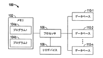
図1を参照すると、例示的なコンピューティングシステム100が示される。システム100は、メモリ102を含むように示される。メモリ102は、実行可能な命令を記憶してもよい。実行可能な命令は、任意の方法で、任意の抽象化レベルで、例えば、1つまたは複数のアプリケーション、プロセス、ルーチン、手順、方法などと関連して記憶または組織化されてもよい。一実施例として、少なくとも一部の命令が、第1のプログラム104aおよび第2のプログラム104bに関連するものとして図1に示される。
With reference to FIG. 1, an
メモリ102に記憶された命令は、1つまたは複数のプロセッサ、例えばプロセッサ106により実行されてもよい。プロセッサ106は、1つまたは複数の入出力(I/O)デバイス108に連結されてもよい。いくつかの実施例において、1つまたは複数のI/Oデバイス108は、キーボードまたはキーパッド、タッチスクリーンまたはタッチパネル、ディスプレイ画面、マイクロホン、スピーカー、マウス、ボタン、リモコン、コントロールスティック、ジョイスティック、プリンター、電話またはモバイルデバイス(例えば、スマートフォン)などのうちの1つ以上を含み得る。1つまたは複数のI/Oデバイス108は、ユーザがシステム100と対話することができるようにインターフェースを提供するように構成されてもよい。
The instructions stored in
示されるように、プロセッサ106は、「n」個のデータベース110−1、110−2、・・・110−nに連結されてもよい。データベース110は、データの保存に使用されてもよい。いくつかの実施例において、そのデータは、歯車に関連し得る。プロセッサ106は、データを操作して、歯車のプロファイルを生成することができる。
As shown, the
システム100は、例示的なものである。いくつかの実施例において、1つまたは複数のエンティティは、任意である。いくつかの実施例において、図示されない追加のエンティティが含まれ得る。例えば、システム100は、ネットワークの一部であってもよい。いくつかの実施例において、エンティティは、図1に示した方法と異なる様式で配置または組織化されてもよい。例えば、いくつかの実施例において、メモリ102は、1つまたは複数のデータベース110に連結されるか、またはそれと組み合わせられてもよい。
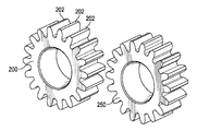
ここで図2を参照すると、例示的な歯車200が示される。歯車200は、いくつかの歯を含むように示される。これらの歯のうちの数個は、図2で202としてラベル付けされている。歯車200は、追加の歯車250と嵌り合うか、または噛み合うことができる。
Referring now to FIG. 2, an
歯車200、250は、例示的なものである。いくつかの実施例において、歯車は、歯車200または歯車250と異なる大きさまたは寸法を有してもよい。いくつかの実施例において、歯車は、歯車200または歯車250より多いまたは少ない歯を含んでもよい。はすば歯車、かさ歯車などを含むすべての種類の歯車が使用されてもよい。
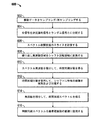
ここで図3を参照すると、例示的な方法300のフローチャートが示される。方法300は、1つまたは複数のシステム、構成要素、またはデバイス、例えば本明細書に記載されるもの(例えばシステム100)により実行されてもよい。方法300を用いて、歯車(例えば、歯車200)のプロファイルを生成することができる。そのプロファイルの分析は、劣化している可能性の高い歯車の1つの歯を特定することができ得る。
Referring now to FIG. 3, a flowchart of an
ブロック302において、歯車は、旋回または回転してもよい。歯車の歯が、例えば第2の歯車(例えば歯車250)の歯と接触するか、または噛み合うときに、この歯車の歯は、衝撃エネルギーまたは振動を受け得る。このエネルギー/振動信号は取得され、データベースまたはメモリに記憶されてもよい。この信号は、その歯車に関連する歯の数と等しいセグメントの数にセグメント化されてもよい。ブロック302の衝撃エネルギーは、実際の物理的なエネルギーに関連し得る。この衝撃エネルギーは、以下でさらに説明される図6によって取得され得る。
In
ブロック302は、歯車の各歯に対して繰り返してもよい。
ブロック304において、プロファイルは、ブロック302の測定に基づいて生成され得る。このプロファイルは、ある期間にわたって歯車が受けるエネルギーまたは振動に対応してもよい。この歯車の歯が、例えば第2の歯車の歯に衝撃を与えるとき、エネルギー/振動に関して比較的大きなスパイクが存在し得る。
In
ブロック306において、このプロファイルは、異常が存在するかを決定するために分析されてもよい。例えば、歯車の歯が同様に構築/配置された場合、このプロファイルは、歯車の歯が第2の歯車の歯と接触するときにエネルギー/振動に関して比較的大きなスパイク、およびその後の比較的低い量のエネルギー/振動を特徴とする、一貫した、または認識可能なパターンを示し得る。このプロファイルが、ある閾値を超える量で一貫したパターンから逸脱する場合、恐らく関連する歯が劣化している可能性があり(例えば、その歯は、ある閾値を超える量で劣化している可能性が高くあり得る)、故障が宣言され得る。
In
この逸脱は、振幅または大きさに関する逸脱に相当し得る。例えば、歯車の特定の歯が劣化している場合、その特定の歯は、歯車の他の歯が受ける衝撃エネルギー/振動より実質的に低いまたは高い衝撃エネルギー/振動を受け得る。この逸脱は、時間に関する逸脱に相当し得る。例えば、歯車の特定の歯が劣化している場合、その特定の歯は、歯車の他の歯が受ける衝撃エネルギー/振動のタイミングよりずれた衝撃エネルギー/振動を受け得る。 This deviation can correspond to an amplitude or magnitude deviation. For example, if a particular tooth of a gear is degraded, that particular tooth may experience impact energy / vibration that is substantially lower or higher than the impact energy / vibration experienced by the other teeth of the gear. This deviation may correspond to a time deviation. For example, if a particular tooth of a gear is degraded, that particular tooth may receive impact energy / vibration that deviates from the impact energy / vibration timing experienced by the other teeth of the gear.
ブロック306の一環として、予想歯衝撃エネルギーの経験的推定値が歯車の各歯に対して生成され得る。この経験的推定値は、隣接歯の衝撃エネルギーを使用し生成してもよく、隣接歯が生成するエネルギーの平均値または3次スプライン補間に潜在的に基づき得る。測定/算出された衝撃エネルギーが隣接歯から得た推定値とは有意に異なる場合、歯車の歯の故障が宣言され得る。
As part of
方法300は、例示的なものである。いくつかの実施例において、1つまたは複数のブロックまたは動作(またはその一部)は、任意であってもよい。いくつかの実施例において、図示されない追加の動作が含まれ得る。いくつかの実施例において、動作は、図3に示す順序または順番と異なる順序または順番で実行されてもよい。
ここで図4を参照すると、システム400が示される。システム400を使用して、歯車箱の振動源の観点での分離を提供することができる。
Now referring to FIG. 4, a
図4に示されるように、駆動モータ402は、モータシャフト406を介して第1の負荷歯車箱404に連結されてもよい。そのモータシャフトは、エンコーダ408およびタコメータ410を含んでもよく、またはそれらに連結されてもよい。
As shown in FIG. 4, the
第1の負荷歯車箱404は、アイドラシャフト414を含んでもよく、またはそれに連結されてもよい。
The first
第1の負荷歯車箱404は、潜在的に入力シャフト422を経由して、第1のテスト歯車箱420に連結されてもよい。第1のテスト歯車箱420は加速度計424を含んでもよく、またはそれに連結されてもよい。第1のテスト歯車箱420はアイドラシャフト426を含んでもよく、またはそれに連結されてもよい。
The first
第1のテスト歯車箱420は、第2のテスト歯車箱430に連結されてもよい。そのような連結の一環として、入力シャフト422は、第1のテスト歯車箱420と第2のテスト歯車箱430との間に延在してもよい。
The first
第2のテスト歯車箱430は、負荷歯車箱440に連結されてもよい。
The second
負荷歯車箱440は、負荷モータ450に連結されてもよい。
The
図4に示されるように、第1の負荷歯車箱404、第1のテスト歯車箱420、第2のテスト歯車箱430、および第2の負荷歯車箱440は、いくつかの歯車を備えてもよい。例えば、モータシャフト406は、例えば19歯(19T)を有する第1の歯車を経由して、第1の負荷歯車箱404に連結されてもよい。次いで、その第1の歯車は、例えば72歯(72T)を有する第2の歯車に連結されてもよい。次いで、その第2の歯車は、アイドラシャフト414に連結されてもよく、アイドラシャフト414は、例えば19歯(19T)を有する第3の歯車に連結されてもよい。次いで、その第3の歯車は、例えば48歯(48T)を有する第4の歯車に連結されてもよい。
As shown in FIG. 4, the first
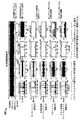
ここで図5を参照すると、いくつかの例示的な波形500が示される。波形500は、システム400の使用に基づいて生成されてもよい。図5に示されるように、波形500は、シャフトにより、決定論的な波形または信号とランダムな波形または信号とに分割されてもよい。ランダムな波形は、従来、歯車の調子監視の目的のために無視され得る。
Referring now to FIG. 5,
波形502で表される第1の波形500は、加速度計424により記録された信号に対応し得る。図5に示されるように、信号502のランダムな部分は、信号502の決定論的な部分より強くてもよい。
A
波形504で表される第2の波形500は、モータシャフト406の振動に対応し得る。
A
波形506で表される第3の波形500は、アイドラシャフト414の振動に対応し得る。
A
波形508で表される第4の波形500は、入力シャフト422の振動に対応し得る。図5に示されるように、5.2kHzの可撓体振動モードが入力シャフト振動508において受けられ得る。入力シャフト422の1回の回転にわたって、23歯(23T)の衝撃がはっきりと明らかであり得る。
A
波形510で表される第5の波形500は、アイドラシャフト426の振動に対応し得る。図5に示されるように、アイドラシャフト426の1回の回転にわたって、44歯(44T)の衝撃がはっきりと明らかであり得る。
A
ここで図6を参照すると、例示的な方法600のフローチャートが示される。方法600は1つまたは複数のシステム、構成要素、またはデバイス、例えば本明細書に記載されるもの(例えば、システム100、システム400)により実行されてもよい。方法600を用いて、特定の歯車箱シャフトに関連する決定論的振動を分離することができる。この点において、方法600は、目的とする各シャフトに対して実行してもよい。
Turning now to FIG. 6, a flowchart of an
ブロック602において、振動データは、振動データが時間ではなくシャフト角回転に関する一定のサンプリング速度を有するようにサンプリングまたは再サンプリングされてもよい。
At
ブロック604において、振動データに対応する全信号は、決定論的信号とランダム信号とに分割されてもよい。
At
ブロック606において、スペクトル相関密度のスライスをシャフトの基本周波数およびその整数倍数で、ブロック604において取得されたランダム信号に基づき得る十分に大きな倍数(例えば、良好な解像度を得るために閾値を超える量の倍数)まで、計算され得る。これらの倍数は、歯車噛み合い位数の多数の倍数を含み得る。
At
ブロック608において、繰り返し周波数領域は、逆フーリエ変換を使用して、シャフト回転(擬似時間)領域に変換されて、1回のシャフト回転にわたってシャフトの時間−周波数の表現(ウィグナー・ビレ(Wigner−Ville)スペクトル)を生成することができる。
At
ブロック610において、スペクトル周波数は、ウィグナー・ビレスペクトルから積分されて、時間同期分散を得ることができる。この時間同期分散は、1回の回転にわたって、回転角度の関数としてシャフト回転により生成されるランダムエネルギーまたは衝撃エネルギーの測定値に対応し得る。
At
ブロック612において、時間同期分散の特徴を使用して、シャフトに特有の故障を検知および分離することができる。
At
ブロック614において、角回転は、ウィグナー・ビレスペクトルから積分されて、時間同期スペクトルを得ることができる。この時間同期スペクトルは、シャフトにより生成されるランダム振動に関連するパワースペクトルの推定値に対応し得る。時間同期スペクトルは、図5で「シャフトXランダム信号」と命名されたグラフに対応してもよく、ここでは「X」は番号である。
In
ブロック616において、時間同期スペクトルの特徴は、歯車箱振動の監視に使用してもよい。
At
方法600は、例示的なものである。いくつかの実施例において、1つまたは複数のブロックまたは動作(またはその一部)は、任意であってもよい。いくつかの実施例において、図示されない追加の動作が含まれ得る。いくつかの実施例において、動作は、図6に示す順序または順番と異なる順序または順番で実行されてもよい。
方法600を用いて、時間同期平均値に類似した様式で、歯車シャフトに特有のランダム振動を分離することができる。シャフトに特有のランダム振動を分離する能力は、微視的現象、例えば、摩擦、消耗、孔食などに関連する故障の検知および分離の改善を可能にし得る。
The
方法600を用いて、残留信号またはランダム信号を取得することができる。例えば、全信号は、時間同期平均信号とランダム信号とに効果的に分解され得る。ランダム信号を分析または処理して、歯車の歯の噛み合いに関連するエネルギー履歴を取得することができる。
The
上述のように、分割トルク歯車箱に関係する初期故障の検知および診断は困難であり得る。歯車噛み合いの力積は、歯車箱の構造体における機械的な波の反射に関連する減衰するランダム信号を生成し得る。信号は、搬送周波数を有してもよく、それは、特性長で割った材料における波の速度と等しくあり得る。その特性長は、歯車箱の構造および加速度計の配置または位置によって決定されてもよい。他の意味で同一である歯車は、1つの加速度計の位置において測定したとき、特性長および搬送周波数が異なり得る。 As mentioned above, detection and diagnosis of initial faults associated with split torque gearboxes can be difficult. The gear meshing impulse may generate a decaying random signal associated with mechanical wave reflections in the gearbox structure. The signal may have a carrier frequency, which may be equal to the wave velocity in the material divided by the characteristic length. The characteristic length may be determined by the structure of the gearbox and the placement or position of the accelerometer. Gears that are otherwise identical may have different characteristic lengths and carrier frequencies when measured at the position of one accelerometer.
ここで図7を参照すると、例示的な方法700のフローチャートが示される。方法700は、例えば本明細書に記載のものなどの1つまたは複数のシステム、構成要素、またはデバイスにより実行されてもよい。方法700を用いて、同一または類似の歯車噛み合いの各々の時間同期分散を計算することができる。
Turning now to FIG. 7, a flowchart of an
ブロック702において、振動データは、振動データが時間ではなくシャフト角回転に関する一定のサンプリング速度を有するようにサンプリングまたは再サンプリングされてもよい。
At
ブロック704において、振動データに対応する全信号は、決定論的な信号とランダム信号とに分割されてもよい。
At
ブロック706において、スペクトル相関密度のスライスをシャフトの基本周波数およびその整数倍数で、十分に大きな倍数(例えば、良好な解像度を得るために閾値を超える量の倍数)まで、計算され得る。これらの倍数は、歯車噛み合い位数のいくつかの倍数を含み得る。
At
ブロック708において、繰り返し周波数領域は、逆フーリエ変換を使用して、シャフト回転(擬似時間)領域に変換されて、1回のシャフト回転にわたってシャフトの時間−周波数の表現(ウィグナー・ビレスペクトル)を生成することができる。
At
ブロック710において、角回転は、ウィグナー・ビレスペクトルから積分されて、時間同期スペクトルを得ることができる。この時間同期スペクトルは、シャフトにより生成されるランダム振動に関連するパワースペクトルの推定値に対応し得る。
In
ブロック712において、歯車噛み合いの数と等しい数のスペクトルピークを特定してもよい。
At
ブロック714において、特定のスペクトルピークと一致する帯におけるスペクトル周波数は、ウィグナー・ビレスペクトルから積分され、歯車噛み合いの各々の独自時間同期分散(1回のシャフト回転にわたってのエネルギー)を得る。
At
方法700は、例示的なものである。いくつかの実施例において、1つまたは複数のブロックまたは動作(またはその一部)は、任意であってもよい。いくつかの実施例において、図示されない追加の動作が含まれ得る。いくつかの実施例において、動作は、図7に示す順序または順番と異なる順序または順番で実行されてもよい。
方法700を用いて、単一の歯車噛み合いが生成する振動エネルギーを監視することができる。振動エネルギーは、他の歯車噛み合いとともに生成される信号から分離されてもよい。
The
本明細書に記載の例示的な実施例および実例は、本開示の態様を歯車、シャフトおよび歯車箱に関連付ける。本開示の態様は他の状況にも、例えば軸受に関する場合に、応用されてもよい。 The illustrative examples and examples described herein relate aspects of the present disclosure to gears, shafts, and gearboxes. Aspects of the present disclosure may be applied to other situations, for example when it relates to bearings.
本明細書に記載されるように、いくつかの実施例において、様々な機能または行為が所定の位置および/または1つまたは複数の装置、システム、またはデバイスの動作に関連して起こり得る。例えば、いくつかの実施例において、所定の機能または行為の一部が第1のデバイスまたは位置で実行され得る一方で、その機能または行為の残りは、1つまたは複数の追加のデバイスまたは位置で実行され得る。 As described herein, in some embodiments various functions or acts may occur in relation to a given location and / or operation of one or more apparatuses, systems, or devices. For example, in some embodiments, some of a given function or action may be performed at a first device or location, while the remainder of the function or action is at one or more additional devices or positions. Can be executed.
実施例は、1つまたは複数の技術を使用して実施されてもよい。いくつかの実施例において、装置またはシステムは、1つまたは複数のプロセッサと、その1つまたは複数のプロセッサにより実行されると、その装置またはシステムに、本明細書に記載の1つまたは複数の方法論的行為を実行させる、命令が記憶されたメモリと、を含み得る。いくつかの実施例において、当業者に知られている様々な機械的構成要素を使用することができる。 Embodiments may be implemented using one or more techniques. In some embodiments, an apparatus or system, when executed by one or more processors and the one or more processors, includes one or more of the apparatus or system described herein. And a memory in which instructions are stored for performing methodological actions. In some embodiments, various mechanical components known to those skilled in the art can be used.
実施例は、1つまたは複数の装置、システム、および/または方法として実施され得る。いくつかの実施例において、命令は、1つまたは複数のコンピュータ可読媒体、例えば一時的および/または非一時的コンピュータ可読媒体に記憶され得る。実行されると、これらの命令は、エンティティ(例えば、装置またはシステム)に本明細書に記載の1つまたは複数の方法論的行為を実行させ得る。 Embodiments may be implemented as one or more devices, systems, and / or methods. In some examples, the instructions may be stored on one or more computer readable media, eg, temporary and / or non-transitory computer readable media. When executed, these instructions may cause an entity (eg, a device or system) to perform one or more methodological acts described herein.
本開示の態様は、その例示的な実施例の観点で説明されてきた。本開示の概説により、当業者であれば、添付の特許請求の範囲および精神内で、多くの他の実施例、修正、および変更を思い付くであろう。例えば、当業者であれば、例示的な図面とともに説明された手順が列挙された順序以外でも実行されてもよく、例示された1つまたは複数の手順が任意であり得ることを理解するであろう。 Aspects of the present disclosure have been described in terms of exemplary embodiments thereof. By review of this disclosure, those skilled in the art will envision many other examples, modifications, and changes within the scope and spirit of the claims appended hereto. For example, those skilled in the art will appreciate that the procedures described in conjunction with the exemplary drawings may be performed in an order other than the listed order, and that one or more illustrated procedures may be optional. Let's go.
Claims (16)
プロセッサを備えるコンピューティングデバイスにより、衝撃エネルギー信号のプロファイルを生成し、
プロファイルの分析に基づいて、複数の歯に含まれる特定の歯に関連する故障を宣言する、
ことを含む、方法。 Obtaining an impact energy signal associated with each of the plurality of teeth of the gear over the rotation of the shaft associated with the gear;
A profile of the impact energy signal is generated by a computing device comprising a processor,
Declaring a failure related to a specific tooth in multiple teeth, based on an analysis of the profile,
Including the method.
推定衝撃エネルギー信号を取得された衝撃エネルギー信号と比較し、
推定衝撃エネルギー信号と取得された衝撃エネルギー信号との間の偏差が閾値を超える量であることを示す比較に基づいて、故障を宣言する、
ことをさらに含むことを特徴とする請求項1に記載の方法。 Generating an estimated impact energy signal corresponding to each tooth of the plurality of teeth;
Compare the estimated impact energy signal with the acquired impact energy signal,
Declaring a failure based on a comparison indicating that the deviation between the estimated impact energy signal and the acquired impact energy signal is an amount that exceeds a threshold;
The method of claim 1 further comprising:
セグメントの数に含まれる各セグメントを積分して、各歯車歯衝撃により解放される全エネルギーを算出する、
ことをさらに含むことを特徴とする請求項1に記載の方法。 Segment the impact energy signal into a number of segments equal to the number of teeth in multiple teeth;
Integrate each segment included in the number of segments to calculate the total energy released by each gear tooth impact,
The method of claim 1 further comprising:
ランダム信号を処理して、歯の噛み合いに関連するエネルギー履歴を取得する、
ことをさらに含むことを特徴とする請求項1に記載の方法。 Split the signal into time synchronous average signal and random signal,
Processing random signals to obtain energy history related to tooth meshing,
The method of claim 1 further comprising:
繰り返し周波数領域表現を回転領域に変換して、シャフトの時間−周波数表現を生成する、
ことをさらに含むことを特徴とする請求項1に記載の方法。 Compute a slice of the spectral correlation density associated with the shaft at the fundamental frequency and multiples of the fundamental frequency to obtain an iterative frequency domain representation,
Transform the repeated frequency domain representation into a rotation domain to generate a time-frequency representation of the shaft,
The method of claim 1 further comprising:
時間同期分散を使用して、シャフトに関連する故障を検知および分離する、
ことをさらに含むことを特徴とする請求項5に記載の方法。 Integrate the spectral frequency from the time-frequency representation to obtain the time-synchronized variance,
Use time-synchronized dispersion to detect and isolate shaft related faults,
The method of claim 5 further comprising:
時間同期スペクトルを使用して、歯車箱の振動を監視する、
ことをさらに含むことを特徴とする請求項5に記載の方法。 Integrate angular rotation from the time-frequency representation to obtain a time-synchronized spectrum,
Use a time-synchronized spectrum to monitor gearbox vibrations,
The method of claim 5 further comprising:
積分されたスペクトル周波数を使用して、歯車噛み合いの各々の独自時間同期分散を取得する、
ことをさらに含むことを特徴とする請求項5に記載の方法。 Integrating the spectral frequency from a time-frequency representation in a band that coincides with a specific spectral peak substantially equal to the number of similar gear meshes;
Use the integrated spectral frequency to obtain a unique time-synchronized variance for each gear mesh,
The method of claim 5 further comprising:
少なくとも1つのプロセッサと、
命令が記憶されたメモリと、
を備え、
命令は、少なくとも1つのプロセッサにより実行されると、装置に、
歯車に関連するシャフトの回転にわたって歯車の複数の歯の各々に関連する衝撃エネルギー信号を取得させ、
衝撃エネルギー信号のプロファイルを生成させ、
プロファイルの分析に基づいて、複数の歯に含まれる特定の歯に関連する故障を宣言させる、
ことを特徴とする、装置。 A device,
At least one processor;
Memory in which instructions are stored;
With
The instructions, when executed by at least one processor,
Obtaining an impact energy signal associated with each of the plurality of teeth of the gear over the rotation of the shaft associated with the gear;
Generate a profile of the impact energy signal,
Based on the analysis of the profile, to declare a failure related to a specific tooth in multiple teeth,
A device characterized by that.
複数の歯の各歯に対応する推定衝撃エネルギー信号を生成させ、
推定衝撃エネルギー信号を取得された衝撃エネルギー信号と比較させ、
推定衝撃エネルギー信号と取得された衝撃エネルギー信号との間の偏差が閾値を超える量であることを示す比較に基づいて、故障を宣言させる、
ことを特徴とする請求項9に記載の装置。 The instructions, when executed by at least one processor,
Generating an estimated impact energy signal corresponding to each tooth of the plurality of teeth;
Compare the estimated impact energy signal with the acquired impact energy signal,
Declare a failure based on a comparison indicating that the deviation between the estimated impact energy signal and the acquired impact energy signal is an amount that exceeds a threshold;
The apparatus according to claim 9.
衝撃エネルギー信号を複数の歯に含まれる歯の数と等しいセグメントの数にセグメント化させ、
セグメントの数に含まれる各セグメントを積分して、各歯車歯衝撃により解放される全エネルギーを算出させる、
ことを特徴とする請求項9に記載の装置。 The instructions, when executed by at least one processor,
Segment the impact energy signal into a number of segments equal to the number of teeth in multiple teeth;
Integrate each segment included in the number of segments to calculate the total energy released by each gear tooth impact,
The apparatus according to claim 9.
衝撃エネルギー信号を時間同期平均信号とランダム信号とに分割させ、
ランダム信号を処理して、歯の噛み合いに関連するエネルギー履歴を取得させる、
ことを特徴とする請求項9に記載の装置。 The instructions, when executed by at least one processor,
The impact energy signal is divided into a time synchronous average signal and a random signal,
Processing random signals to obtain energy history related to tooth engagement,
The apparatus according to claim 9.
基本周波数および基本周波数の倍数でシャフトに関連するスペクトル相関密度のスライスを計算して、繰り返し周波数領域表現を取得させ、
逆フーリエ変換を使用して、繰り返し周波数領域表現を回転領域に変換して、シャフトの時間−周波数表現を生成させる、
ことを特徴とする請求項9に記載の装置。 The instructions, when executed by at least one processor,
Calculate a slice of spectral correlation density associated with the shaft at the fundamental frequency and multiples of the fundamental frequency to obtain a repetitive frequency domain representation,
Using an inverse Fourier transform to transform a repetitive frequency domain representation into a rotational domain to produce a time-frequency representation of the shaft,
The apparatus according to claim 9.
時間−周波数表現からスペクトル周波数を積分して、時間同期分散を取得させ、
時間同期分散を使用して、シャフトに関連する故障を検知および分離させる、
ことを特徴とする請求項13に記載の装置。 The instructions, when executed by at least one processor,
Integrate spectral frequency from time-frequency representation to get time-synchronized variance,
Use time-synchronized dispersion to detect and isolate shaft related faults,
The apparatus of claim 13.
時間−周波数表現から角回転を積分して、時間同期スペクトルを取得させ、
時間同期スペクトルを使用して、歯車およびシャフトに関連する歯車箱の振動を監視させる、
ことを特徴とする請求項13に記載の装置。 The instructions, when executed by at least one processor,
Integrate angular rotation from the time-frequency representation to get a time-synchronized spectrum,
Use time-synchronized spectrum to monitor gearbox vibrations associated with gears and shafts,
The apparatus of claim 13.
歯車噛み合いの数と等しい特定のスペクトルピークと一致する帯における時間−周波数表現からスペクトル周波数を積分させ、
積分されたスペクトル周波数を使用して、歯車噛み合いの各々の独自時間同期分散を取得させる、
ことを特徴とする請求項13に記載の装置。 The instructions, when executed by at least one processor,
Integrating the spectral frequency from a time-frequency representation in a band that coincides with a specific spectral peak equal to the number of gear meshes,
Use the integrated spectral frequency to obtain a unique time-synchronized variance for each of the gear meshes,
The apparatus of claim 13.
Applications Claiming Priority (3)
| Application Number | Priority Date | Filing Date | Title |
|---|---|---|---|
| US14/035,227 | 2013-09-24 | ||
| US14/035,227 US9482647B2 (en) | 2013-09-24 | 2013-09-24 | Gear fault detection |
| PCT/US2014/057136 WO2015048078A1 (en) | 2013-09-24 | 2014-09-24 | Gear fault detection |
Related Child Applications (1)
| Application Number | Title | Priority Date | Filing Date |
|---|---|---|---|
| JP2019238441A Division JP2020064075A (en) | 2013-09-24 | 2019-12-27 | Detection of gear failure |
Publications (1)
| Publication Number | Publication Date |
|---|---|
| JP2017500535A true JP2017500535A (en) | 2017-01-05 |
Family
ID=52691687
Family Applications (2)
| Application Number | Title | Priority Date | Filing Date |
|---|---|---|---|
| JP2016516523A Pending JP2017500535A (en) | 2013-09-24 | 2014-09-24 | Gear failure detection |
| JP2019238441A Pending JP2020064075A (en) | 2013-09-24 | 2019-12-27 | Detection of gear failure |
Family Applications After (1)
| Application Number | Title | Priority Date | Filing Date |
|---|---|---|---|
| JP2019238441A Pending JP2020064075A (en) | 2013-09-24 | 2019-12-27 | Detection of gear failure |
Country Status (4)
| Country | Link |
|---|---|
| US (1) | US9482647B2 (en) |
| EP (1) | EP3049788B1 (en) |
| JP (2) | JP2017500535A (en) |
| WO (1) | WO2015048078A1 (en) |
Cited By (1)
| Publication number | Priority date | Publication date | Assignee | Title |
|---|---|---|---|---|
| JP7403025B1 (en) | 2023-05-22 | 2023-12-21 | 哈尓濱船舶鍋炉渦輪机研究所(中国船舶集団有限公司第七〇三研究所) | Connection device between a test box and an attached test box for planetary back-to-back tests |
Families Citing this family (18)
| Publication number | Priority date | Publication date | Assignee | Title |
|---|---|---|---|---|
| US9599535B2 (en) * | 2015-05-19 | 2017-03-21 | GM Global Technology Operations LLC | Method and apparatus for excitation of gear rattle |
| CN106195222B (en) * | 2015-05-29 | 2020-10-09 | Zf腓德烈斯哈芬股份公司 | Method for monitoring the state of at least one planet wheel of a planetary gear set |
| FR3047803B1 (en) * | 2016-02-12 | 2018-03-23 | Ntn-Snr Roulements | METHOD FOR DETECTING A VIBRATORY STATE OF A MECHANICAL ASSEMBLY COMPRISING A ROTATING ORGAN |
| US10380810B2 (en) | 2016-08-17 | 2019-08-13 | Bell Helicopter Textron Inc. | Diagnostic method, system and device for a rotorcraft drive system |
| US10424134B2 (en) | 2016-08-17 | 2019-09-24 | Bell Helicopter Textron Inc. | Diagnostic method, system and device for a rotorcraft drive system |
| US10643405B2 (en) * | 2016-08-17 | 2020-05-05 | Bell Helicopter Textron Inc. | Diagnostic method, system and device for a rotorcraft drive system |
| US10464689B2 (en) | 2016-08-17 | 2019-11-05 | Bell Helicopter Textron Inc. | Diagnostic method, system and device for a rotorcraft drive system |
| FR3065267A1 (en) * | 2017-04-18 | 2018-10-19 | Airbus Helicopters | GEARED GEAR WHEEL, GEAR DEVICE, POWER TRANSMISSION BOX AND AIRCRAFT HAVING A ROTATING VESSEL |
| CN107290043B (en) * | 2017-06-15 | 2023-07-28 | 贵州电网有限责任公司电力科学研究院 | Online distributed monitoring method for vibration times of power transmission line |
| FR3069668B1 (en) * | 2017-07-27 | 2021-02-12 | Safran | METHOD AND DEVICE FOR SEARCHING FOR A FAULT LIKELY TO AFFECT A ROTATING MECHANICAL POWER TRANSMISSION DEVICE |
| DE102017119543A1 (en) * | 2017-08-25 | 2019-02-28 | Rolls-Royce Deutschland Ltd & Co Kg | Method and device for monitoring a sliding bearing |
| CN107944199B (en) * | 2017-12-22 | 2020-12-01 | 浙江工业大学 | Gear box fault identification method based on frequency spectrum trend and variational modal decomposition |
| US11043046B2 (en) * | 2018-03-08 | 2021-06-22 | Textron Innovations Inc. | Failure detection system |
| CN109754442B (en) * | 2019-01-10 | 2023-02-21 | 重庆大学 | Gear pitting detection system based on machine vision |
| CN110646200B (en) * | 2019-09-04 | 2021-10-22 | 天津工业大学 | Method for diagnosing weak local fault of gear of fixed shaft gear box |
| CN110844111B (en) * | 2019-10-11 | 2022-11-04 | 中国直升机设计研究所 | Multi-characteristic index bevel gear health state assessment method |
| CN111896257B (en) * | 2020-07-15 | 2022-03-18 | 江门职业技术学院 | Rolling bearing fault diagnosis method and system |
| CN113309844B (en) * | 2021-05-08 | 2022-02-18 | 郑州轻工业大学 | Gear fault detection equipment and fault detection method |
Citations (7)
| Publication number | Priority date | Publication date | Assignee | Title |
|---|---|---|---|---|
| JPH07311082A (en) * | 1994-05-20 | 1995-11-28 | Omron Corp | Failure diagnostic device of rotating equipment |
| JPH09210765A (en) * | 1996-01-30 | 1997-08-15 | Oki Electric Ind Co Ltd | Feature extractor for cyclic motion state |
| US5895857A (en) * | 1995-11-08 | 1999-04-20 | Csi Technology, Inc. | Machine fault detection using vibration signal peak detector |
| US6526356B1 (en) * | 2001-06-19 | 2003-02-25 | The Aerospace Corporation | Rocket engine gear defect monitoring method |
| JP2008107294A (en) * | 2006-10-27 | 2008-05-08 | Omron Corp | Signal extraction method, signal extraction device, and machine inspection apparatus |
| JP2010236929A (en) * | 2009-03-30 | 2010-10-21 | Jatco Ltd | Nick detection device of gear, and nick detection method of gear |
| US7912659B2 (en) * | 2004-06-28 | 2011-03-22 | General Electric Company | System and method for monitoring the condition of a drive train |
Family Cites Families (14)
| Publication number | Priority date | Publication date | Assignee | Title |
|---|---|---|---|---|
| US3277695A (en) | 1961-06-22 | 1966-10-11 | Sperry Rand Corp | Vibration analyzer |
| US3699806A (en) | 1967-07-14 | 1972-10-24 | Bjorn Weichbrodt | Early detection of damage to machine elements in rolling engagement |
| US6507789B1 (en) | 2000-07-18 | 2003-01-14 | General Electric Company | Gear transmission condition monitoring method and apparatus |
| US6711523B2 (en) * | 2001-05-24 | 2004-03-23 | Simmonds Precision Products, Inc. | Method and apparatus for determining a condition indicator for use in evaluating the health of a component |
| US6681634B2 (en) | 2001-12-11 | 2004-01-27 | Itt Manufacturing Enterprises, Inc. | Bearing defect detection using time synchronous averaging (TSA) of an enveloped accelerometer signal |
| CA2440792A1 (en) | 2002-09-27 | 2004-03-27 | Mechworks Systems Inc. | A method and system for online condition monitoring of multistage rotary machinery |
| EP1588138A1 (en) | 2003-01-24 | 2005-10-26 | The Commonwealth of Australia as represented by the Defence Science and Technology Organisation of the Department of Defence | Synchronous averaging of epicyclic sun gear vibration |
| EP1459816B1 (en) * | 2003-03-15 | 2006-09-06 | Trumpf Werkzeugmaschinen GmbH + Co. KG | Bending device with multi-level bending tool, clamping jaw unit and sliding support unit for such a bending device |
| US7318007B2 (en) | 2003-12-31 | 2008-01-08 | United Technologies Corporation | Real time gear box health management system and method of using the same |
| US7317994B2 (en) | 2005-08-10 | 2008-01-08 | General Electric Company | Method and apparatus for signal signature analysis for event detection in rotating machinery |
| CA2687785C (en) * | 2008-12-04 | 2015-09-15 | University Of Ottawa | Parameter independent detection of rotating machinery faults |
| US7945397B2 (en) | 2009-04-02 | 2011-05-17 | Honeywell International Inc. | System and method for gearbox health monitoring |
| US8473252B2 (en) | 2010-06-09 | 2013-06-25 | Honeywell International Inc. | System and method for conflict resolution to support simultaneous monitoring of multiple subsystems |
| EP2549257B1 (en) | 2011-07-18 | 2013-10-30 | Siemens Aktiengesellschaft | Method for detecting damage to drives |
-
2013
- 2013-09-24 US US14/035,227 patent/US9482647B2/en active Active
-
2014
- 2014-09-24 WO PCT/US2014/057136 patent/WO2015048078A1/en active Application Filing
- 2014-09-24 EP EP14847091.7A patent/EP3049788B1/en not_active Not-in-force
- 2014-09-24 JP JP2016516523A patent/JP2017500535A/en active Pending
-
2019
- 2019-12-27 JP JP2019238441A patent/JP2020064075A/en active Pending
Patent Citations (7)
| Publication number | Priority date | Publication date | Assignee | Title |
|---|---|---|---|---|
| JPH07311082A (en) * | 1994-05-20 | 1995-11-28 | Omron Corp | Failure diagnostic device of rotating equipment |
| US5895857A (en) * | 1995-11-08 | 1999-04-20 | Csi Technology, Inc. | Machine fault detection using vibration signal peak detector |
| JPH09210765A (en) * | 1996-01-30 | 1997-08-15 | Oki Electric Ind Co Ltd | Feature extractor for cyclic motion state |
| US6526356B1 (en) * | 2001-06-19 | 2003-02-25 | The Aerospace Corporation | Rocket engine gear defect monitoring method |
| US7912659B2 (en) * | 2004-06-28 | 2011-03-22 | General Electric Company | System and method for monitoring the condition of a drive train |
| JP2008107294A (en) * | 2006-10-27 | 2008-05-08 | Omron Corp | Signal extraction method, signal extraction device, and machine inspection apparatus |
| JP2010236929A (en) * | 2009-03-30 | 2010-10-21 | Jatco Ltd | Nick detection device of gear, and nick detection method of gear |
Cited By (1)
| Publication number | Priority date | Publication date | Assignee | Title |
|---|---|---|---|---|
| JP7403025B1 (en) | 2023-05-22 | 2023-12-21 | 哈尓濱船舶鍋炉渦輪机研究所(中国船舶集団有限公司第七〇三研究所) | Connection device between a test box and an attached test box for planetary back-to-back tests |
Also Published As
| Publication number | Publication date |
|---|---|
| EP3049788A1 (en) | 2016-08-03 |
| US20150088435A1 (en) | 2015-03-26 |
| EP3049788B1 (en) | 2018-07-04 |
| WO2015048078A1 (en) | 2015-04-02 |
| EP3049788A4 (en) | 2017-05-03 |
| JP2020064075A (en) | 2020-04-23 |
| US9482647B2 (en) | 2016-11-01 |
Similar Documents
| Publication | Publication Date | Title |
|---|---|---|
| JP2020064075A (en) | Detection of gear failure | |
| Liang et al. | A windowing and mapping strategy for gear tooth fault detection of a planetary gearbox | |
| Wang et al. | A wavelet approach to fault diagnosis of a gearbox under varying load conditions | |
| Chen et al. | Dynamic simulation of spur gear with tooth root crack propagating along tooth width and crack depth | |
| Mohammed et al. | Dynamic response and time-frequency analysis for gear tooth crack detection | |
| Sharma et al. | Frequency domain averaging based experimental evaluation of gear fault without tachometer for fluctuating speed conditions | |
| Sharma et al. | Gear crack detection using modified TSA and proposed fault indicators for fluctuating speed conditions | |
| Staszewski et al. | Local tooth fault detection in gearboxes using a moving window procedure | |
| KR101857355B1 (en) | failure detection method for rotating machinery using Wavelet Entropy(WE) and Cyclic Logarithmic Envelope Spectrum(CLES) | |
| Mączak | Local meshing plane analysis as a source of information about the gear quality | |
| Baudin et al. | Non-intrusive rattle noise detection in non-stationary conditions by an angle/time cyclostationary approach | |
| Buzzoni et al. | Diagnosis of localized faults in multistage gearboxes: a vibrational approach by means of automatic EMD-based algorithm | |
| Diehl et al. | Predictive modeling of a two-stage gearbox towards fault detection | |
| Elbarghathi et al. | Two stage helical gearbox fault detection and diagnosis based on continuous wavelet transformation of time synchronous averaged vibration signals | |
| KR20220075322A (en) | Analysis systems and methods for gear testing | |
| Hong et al. | Vibration based diagnosis for planetary gearboxes using an analytical model | |
| Wang et al. | A model-based gear diagnostic technique | |
| Jauregui-Correa | The effect of nonlinear traveling waves on rotating machinery | |
| Zhao et al. | Flexible time domain averaging technique | |
| Fu et al. | Application of Bi-cepstrum analysis to gear fault detection and diagnosis | |
| Hartono et al. | Vibration-based fault diagnostic of a spur gearbox | |
| Maczak | Evolution of the instantaneous distribution of energy density on a local meshing plane as the measure of gear failures | |
| JP4209793B2 (en) | Abnormality diagnosis method based on acoustic signal and program used for executing the method | |
| Dongjiang et al. | Calculation of Time-Varying Mesh Stiffness of Internal Gears based on Precise Tooth Profile and Dynamic Analysis of Planetary Systems with Root Cracks | |
| Niehaus | Informative frequency band selection for performing envelope analysis under fluctuating operating conditions in the presence of strong noise and deterministic components |
Legal Events
| Date | Code | Title | Description |
|---|---|---|---|
| A621 | Written request for application examination |
Free format text: JAPANESE INTERMEDIATE CODE: A621 Effective date: 20170913 |
|
| A977 | Report on retrieval |
Free format text: JAPANESE INTERMEDIATE CODE: A971007 Effective date: 20180831 |
|
| A131 | Notification of reasons for refusal |
Free format text: JAPANESE INTERMEDIATE CODE: A131 Effective date: 20180918 |
|
| A601 | Written request for extension of time |
Free format text: JAPANESE INTERMEDIATE CODE: A601 Effective date: 20181217 |
|
| A601 | Written request for extension of time |
Free format text: JAPANESE INTERMEDIATE CODE: A601 Effective date: 20190215 |
|
| A521 | Request for written amendment filed |
Free format text: JAPANESE INTERMEDIATE CODE: A523 Effective date: 20190311 |
|
| A02 | Decision of refusal |
Free format text: JAPANESE INTERMEDIATE CODE: A02 Effective date: 20190827 |