JP2017500181A - Adjustable hand tools - Google Patents
Adjustable hand tools Download PDFInfo
- Publication number
- JP2017500181A JP2017500181A JP2016557868A JP2016557868A JP2017500181A JP 2017500181 A JP2017500181 A JP 2017500181A JP 2016557868 A JP2016557868 A JP 2016557868A JP 2016557868 A JP2016557868 A JP 2016557868A JP 2017500181 A JP2017500181 A JP 2017500181A
- Authority
- JP
- Japan
- Prior art keywords
- hand tool
- protruding member
- active
- grip
- tool according
- Prior art date
- Legal status (The legal status is an assumption and is not a legal conclusion. Google has not performed a legal analysis and makes no representation as to the accuracy of the status listed.)
- Pending
Links
Images


Classifications
-
- B—PERFORMING OPERATIONS; TRANSPORTING
- B26—HAND CUTTING TOOLS; CUTTING; SEVERING
- B26B—HAND-HELD CUTTING TOOLS NOT OTHERWISE PROVIDED FOR
- B26B13/00—Hand shears; Scissors
- B26B13/12—Hand shears; Scissors characterised by the shape of the handles
-
- A—HUMAN NECESSITIES
- A61—MEDICAL OR VETERINARY SCIENCE; HYGIENE
- A61B—DIAGNOSIS; SURGERY; IDENTIFICATION
- A61B17/00—Surgical instruments, devices or methods, e.g. tourniquets
- A61B17/32—Surgical cutting instruments
- A61B17/3201—Scissors
-
- B—PERFORMING OPERATIONS; TRANSPORTING
- B25—HAND TOOLS; PORTABLE POWER-DRIVEN TOOLS; MANIPULATORS
- B25B—TOOLS OR BENCH DEVICES NOT OTHERWISE PROVIDED FOR, FOR FASTENING, CONNECTING, DISENGAGING OR HOLDING
- B25B7/00—Pliers; Other hand-held gripping tools with jaws on pivoted limbs; Details applicable generally to pivoted-limb hand tools
- B25B7/18—Adjusting means for the operating arms
-
- B—PERFORMING OPERATIONS; TRANSPORTING
- B25—HAND TOOLS; PORTABLE POWER-DRIVEN TOOLS; MANIPULATORS
- B25B—TOOLS OR BENCH DEVICES NOT OTHERWISE PROVIDED FOR, FOR FASTENING, CONNECTING, DISENGAGING OR HOLDING
- B25B9/00—Hand-held gripping tools other than those covered by group B25B7/00
Abstract
本発明は手工具1に関し、手工具1は、旋回軸30の周りを旋回するように配置される第1の要素2および第2の要素32を備え、第1および第2の要素は、各々、活動部分4,34およびグリップ部分6,36を備え、第1および/または第2の要素の活動部分およびグリップ部分は、調整旋回軸10,42の周りを旋回するように配置され、活動部分およびグリップ部分を互いに対して所定の位置にロック可能とするロック手段12,44が設けられる。The present invention relates to a hand tool 1, which comprises a first element 2 and a second element 32 arranged to swivel about a pivot axis 30, wherein the first and second elements are each The active part 4, 34 and the grip part 6, 36, wherein the active part and the grip part of the first and / or second element are arranged to pivot about the adjustment pivot axis 10, 42, And locking means 12, 44 are provided that allow the grip portions to be locked in place relative to each other.
Description
本発明は、調整可能な手工具、特に1丁のはさみ、大ばさみ、または鉗子に関する。 The present invention relates to an adjustable hand tool, in particular a single scissor, large shear or forceps.
はさみおよびあらゆる種類の鉗子などの手工具は一般的に、回転軸の周りを回転するために互いに接続された2つの剛性要素を備える。両方の剛性要素は一方の外端にグリップ部分を備え、他方の外端において活動部分が設けられる。この活動部分は、はさみの場合には切刃とも称される刃部を備え、鉗子の場合には、活動部分にあごを設けることができる。 Hand tools, such as scissors and all types of forceps, typically comprise two rigid elements connected to one another for rotation about a rotation axis. Both rigid elements are provided with a grip part at one outer end and an active part at the other outer end. In the case of scissors, this active part comprises a blade part, also called a cutting blade, and in the case of forceps, the active part can be provided with a jaw.
たとえば美容師および外科医の作業中の場合のように、正確にかつ/または異なる位置で作動することが必要な動作については、手工具は、剛性要素において角度を有して利用可能である。そのような場合、ユーザは、角度が変動する複数の手工具、たとえば第1の直線の連続的な手工具と、ハンドルと活動部分との間の角度が30°である第2の手工具と、ハンドルと活動部分との間の角度が45°である第3の手工具とを利用可能である。 For operations that need to be operated accurately and / or at different positions, such as when working for hairdressers and surgeons, hand tools are available at an angle in the rigid element. In such a case, the user may have a plurality of hand tools with varying angles, for example a first straight continuous hand tool, and a second hand tool with an angle between the handle and the active part of 30 °. A third hand tool with an angle between the handle and the active part of 45 ° is available.
ユーザは、所望の体勢および手工具によって取扱われる対象物の所望の視界に依存して所望の角度を選択する。工具を変更することができることにより、ユーザは快適かつ健全な姿勢を取ることが可能となり、良好な視界が手作業の品質に貢献する。 The user selects the desired angle depending on the desired posture and the desired field of view of the object being handled by the hand tool. The ability to change the tool allows the user to take a comfortable and healthy posture, and good visibility contributes to the quality of manual work.
特に所望の角度の変動に加えて、ユーザが異なる種類の手工具も必要とする場合、ユーザはすぐに多数の手工具を有することになる。 Especially if the user also needs different types of hand tools in addition to the desired angle variation, the user will soon have a large number of hand tools.
プロの美容師が自由裁量で4丁のはさみ、つまり角度が異なる1組の通常のはさみおよび1丁のすきばさみを有することは珍しいことではない。同様に、外科医は、相当な数の異なる手工具を自由裁量で有することが多い。 It is not uncommon for a professional hairdresser to have 4 scissors at their discretion, that is, a pair of normal scissors and a pair of scissors at different angles. Similarly, surgeons often have a significant number of different hand tools at their discretion.
専門的なはさみおよび外科用鉗子などの手工具は非常に高級な材料から製造されるため、一般に非常に高価である。1つの手工具当たり数百ユーロの原価価格は珍しくない。 Hand tools such as professional scissors and surgical forceps are generally very expensive because they are manufactured from very premium materials. A cost price of several hundred euros per hand tool is not uncommon.
本発明は、上記欠点が生じないか、または少なくともあまり生じない上記の種類の手工具を提供することを目的とする。 The present invention aims to provide a hand tool of the above kind which does not cause, or at least not so much, the above drawbacks.
上記目的は、旋回軸の周りを旋回するように配置される第1の要素および第2の要素を備え、第1および第2の要素は、各々、活動部分およびグリップ部分を備え、第1および/または第2の要素の活動部分およびグリップ部分は、調整旋回軸の周りを旋回するように配置され、活動部分およびグリップ部分を互いに対して所定の位置においてロック可能とするロック手段が設けられる手工具によって本発明に従って実現される。 The object comprises a first element and a second element arranged to pivot about a pivot axis, the first and second elements each comprising an active part and a grip part, The active part and the grip part of the second element are arranged to pivot about the adjusting pivot axis and are provided with locking means that allow the active part and the grip part to be locked in place relative to each other Implemented according to the present invention by a tool.
手工具の一方または両方の要素の活動部分およびグリップ部分は互いに対して調整可能であり、異なる位置にロック可能であるため、ユーザにとって最も快適な位置に手工具を調整することができる。 The active part and the grip part of one or both elements of the hand tool can be adjusted relative to each other and can be locked in different positions, so that the hand tool can be adjusted to the most comfortable position for the user.
各要素が別個の活動部分およびグリップ部分を備えることのさらなる利点は、それらを分解することができる点である。これにより、部品のうちの1つを交換する機会が提供される。 A further advantage of each element comprising a separate active part and grip part is that they can be disassembled. This provides an opportunity to replace one of the parts.
第1の要素および第2の要素の両方の活動部分およびグリップ部分が調整旋回軸の周りで調整可能である場合、特に有利な好ましい実施形態が得られる。調整可能な形態を与えられることによって、両方の要素を所定の方向にともに調整することができ、それにより調整幅が増大する。両方のグリップ部分は、それらを扱うことができる互いの範囲内に結局位置しなければならない。たとえば、第1のグリップ部は、ユーザの親指によって操作され、第2のグリップ部分はユーザの同じ手の別の指によって操作される。 A particularly advantageous preferred embodiment is obtained when the active part and the grip part of both the first element and the second element are adjustable around an adjustment pivot axis. Given the adjustable form, both elements can be adjusted together in a given direction, thereby increasing the adjustment range. Both grip portions must eventually be located within each other's range to handle them. For example, the first grip portion is operated by the user's thumb, and the second grip portion is operated by another finger of the same hand of the user.
さらなる好ましい実施形態によれば、ロック手段は、グリップ部分に、または活動部分に配置された少なくとも2つの凹部と、グリップ部分または活動部分の他方の部分上に配置され、ロック位置と解放位置との間で移動可能な突出部材とを備え、ロック位置において、突出部材は凹部のうちの1つと係合し、解放位置において、突出部材は、活動部分およびグリップ部分が互いに対して調整可能であるように凹部を解放する。突出部材を凹部に係合させることによって、ぴったり合い、かつしたがって操作上確実なロックが得られる。ぴったり合う係合は、確実に、ロックが摩擦に基づくことによるリスクである滑りによる望ましくない調整を妨げる。使用中の望ましくない調整は、たとえば美容師または外科医が偶然に間違って切断するなどの望ましくない結果を引起す可能性がある。 According to a further preferred embodiment, the locking means are arranged on the grip part or on the other part of the active part and at least two recesses arranged on the active part and between the locked position and the released position. A projecting member movable between the projecting member, in the locked position, the projecting member engages one of the recesses, and in the released position, the projecting member is such that the active part and the grip part are adjustable relative to each other. To release the recess. By engaging the protruding member in the recess, a snug and thus operationally secure lock is obtained. The snug engagement reliably prevents unwanted adjustment due to slipping, which is a risk due to the lock being based on friction. Undesirable adjustments in use can cause undesirable results, for example, a hairdresser or surgeon accidentally cuts accidentally.
さらに別の好ましい実施形態によれば、少なくとも2つの凹部がグリップ部分に配置され、突出部材が活動部分上に配置されるため、活動部分は大部分が手段がないままであり得る。ユーザはこれによって、自分が行っていることについて良好な視界を維持する。美容師はたとえば、切刃に沿って遮られていない髪を眺めることができる。突出部材は、ロック位置と解放位置との間で再び移動可能である。 According to yet another preferred embodiment, at least two recesses are arranged in the grip part and the protruding member is arranged on the active part, so that the active part can remain largely without means. The user thereby maintains a good view of what he is doing. The hairdresser can, for example, look at the unobstructed hair along the cutting edge. The protruding member is movable again between the locked position and the released position.
また、グリップ部分上に配置することで、突出部材を板ばねで付勢するための十分な空間が生じる。これはさらなる好ましい実施形態である。 Moreover, sufficient space for energizing a protrusion member with a leaf | plate spring arises by arrange | positioning on a grip part. This is a further preferred embodiment.
突出部材がばねによってロック位置に押付けられるように、突出部材は好ましくはばねによって付勢される。このばねは、好ましくは板ばねである。板ばねはより多くの空間を必要とし、したがって、より小型のコイルばねより劣っていると感じられ得るが、板ばねは閉塞する傾向が低いことにより好ましい実施形態となる。板ばねが清潔なままであるのに対し、手工具が美容師のはさみを備える場合、髪の一部がコイルばねに容易に挟まり得る。板ばねは、医療用手工具の場合と同じく、衛生が重要である場合に利点をもたらす。 The protruding member is preferably biased by the spring so that the protruding member is pressed into the locked position by the spring. This spring is preferably a leaf spring. Although leaf springs require more space and may therefore feel inferior to smaller coil springs, leaf springs are a preferred embodiment due to their low tendency to block. Where the leaf spring remains clean, if the hand tool is provided with a hairdresser's scissors, a portion of the hair can easily be pinched by the coil spring. Leaf springs provide benefits when hygiene is important, as is the case with medical hand tools.
さらに別の好ましい実施形態に従って、突出部材が、回転非対称断面を有するガイド部分および/またはロック部分を備える場合、突出部材は、その長手方向の周りに回転可能であることが妨げられる。したがって、突出部材のロック部分が、常に、したがって解放位置に一時的に位置する時にも、選択された凹部とロック位置で係合するように配置されることができる位置に留まることを実現することが可能である。 In accordance with yet another preferred embodiment, if the protruding member comprises a guide portion and / or a locking portion having a rotationally asymmetric cross section, the protruding member is prevented from being rotatable about its longitudinal direction. Thus, it is realized that the locking part of the protruding member always remains in a position where it can be arranged to engage with the selected recess in the locking position, even when temporarily in the releasing position Is possible.
突出部材が面取りされた形態を有するロック部分を備える場合、さらに有利な実施形態が得られる。この面取りされた形態により、ばねによって付勢される突出部材は、凹部とのぴったり合う係合に常に導かれることになる。 A further advantageous embodiment is obtained when the protruding member comprises a locking part having a chamfered configuration. With this chamfered configuration, the projecting member biased by the spring will always be guided into a close engagement with the recess.
面取りされた形態と、面取りされた突出部材によってその端縁に密接して係合される管状の凹部とを備える突出部材のみを想定することが可能であるが、さらなる好ましい実施形態に従って突出部材の面取り部と共働する面取りされた形態が凹部に設けられている場合、面取りされた突出部材と凹部との間の接触面領域の増大が得られる。 Although it is possible to envisage only a projecting member comprising a chamfered form and a tubular recess that is closely engaged to the edge thereof by a chamfered projecting member, the projection member according to a further preferred embodiment When the chamfered form cooperating with the chamfered portion is provided in the recess, an increase in the contact surface area between the chamfered protruding member and the recess is obtained.
さらに別の好ましい実施形態によれば、突出部材はプレス部分を備え、面取りされた形態は、プレス部分から離れる方向に厚くなる。プレス部分を指で押すことによって、ユーザは(ばね板)ばねの付勢を解放することができ、それによって突出部材が解放位置に移動され、活動部分とグリップ部分との間の角度が調整可能である。 According to yet another preferred embodiment, the protruding member comprises a press part, and the chamfered form is thicker in the direction away from the press part. By pressing the press part with a finger, the user can release the spring bias (spring plate), thereby moving the protruding member to the release position and adjusting the angle between the active part and the grip part It is.
さらなる好ましい実施形態によれば、手工具は1丁のはさみであり、活動部分は切刃を備える。 According to a further preferred embodiment, the hand tool is a single scissor and the active part comprises a cutting edge.
代替的な好ましい実施形態によれば、手工具は1丁の鉗子であり、活動部分はあごを備える。 According to an alternative preferred embodiment, the hand tool is a single forceps and the active part comprises a chin.
図面を参照して、本発明の好ましい実施形態について以下の記載でさらに説明する。 Preferred embodiments of the present invention will be further described in the following description with reference to the drawings.
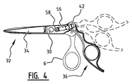
図1〜図4に示される手工具1は、旋回軸30の周りを旋回するように配置された2つの要素2,32を有する1丁のはさみである。両方の要素2,32は、活動部分4,34およびグリップ部分6,36を備える。1丁のはさみの場合、活動部分4,34は切刃である。
The
図示のはさみ1では、第1のグリップ部6は親指穴8を備え、第2の活動部分34には、薬指穴38および小指タング40が設けられている。
In the illustrated
活動部分4,34およびグリップ部分6,36は、調整旋回軸10,42の周りを旋回するように配置され、活動部分4,34およびグリップ部分6,36を互いに対して所定の位置にロック可能とするロック手段12,44がさらに設けられる。
The
活動部分4,34がそれぞれのグリップ部分6,36に対して調整可能である所定の位置は、凹部14,46によって規定される。図示の実施形態の各場合において3つの凹部14,46が設けられ、それによって、図示のはさみ1の各要素2,32は3つの位置において調整可能である。活動部分4,34およびグリップ部分6,36は、それぞれの調整旋回軸10,42を中心に調整中に旋回する。
The predetermined positions at which the
図2は、第1の要素2の3つの可能な位置を示し、図4は、第2の要素32の3つの可能な位置を示す。
FIG. 2 shows three possible positions of the
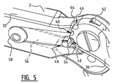
両方の要素2,32は同様の調整機構を備えるため、図5〜図7を参照して第2の要素32の調整機構を以下で説明すれば十分である。
Since both
図5の斜視詳細図では、第2の要素32のグリップ部分36には3つの凹部46が設けられている。図示の状況では、下側の凹部46は、突出部材48のロック部分54によってぴったり合うように係合される。ガイド部分52の板ばね56およびプレス部分50は、明瞭にするために破線で示される。板ばね56は、第2の要素32にボルト58で取付けられる。
In the detailed perspective view of FIG. 5, three
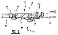
突出部材48は、図6により詳細に示され、プレス部分50、ガイド部分52およびロック部分54を備える。板ばね56のバネ付勢が解消されるようにプレス部分50が力で押されると、突出部材48は、第2の要素32の活動部分34の方向に移動することになる。これによってロック部分54が凹部46から摺動し、突出部材48が解放位置に位置する。この解放位置において、グリップ部分36および活動部分34の間の相対位置が調整可能である。
The protruding
過度の回転を妨げるために、最も外側の位置において第2の要素32の止め部分64に当接する止め突起62が設けられる。
In order to prevent excessive rotation, a
所望の位置が設定され、プレス部分50が解放されるとすぐに、板ばね56が第2の要素32から離れる方に突出部材48を再び移動させることになり、それによって突出部材48が再びロック位置に移動し、活動部分34とグリップ部分36とのさらなる相対回転を妨げる。
As soon as the desired position is set and the
図示の好ましい実施形態では、ガイド部分52には回転非対称形態が設けられているため、突出部材48のための長手方向ガイドとして機能し、突出部材48はその長手軸の周りを回転可能であることが妨げられる。この目的で、突出部材48の非円形形態は、第2の要素32の活動部分34に配置された凹部によってぴったり合うように包囲される。
In the preferred embodiment shown, the
図7は、第2の要素32の断面を示す。凹部60は、旋回ボルト30を用いて第2の要素32を第1の要素2に旋回可能に接続することを可能にするように設けられる。
FIG. 7 shows a cross section of the
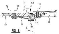
代替的な調整機構が図8に示され、突出部材148は、面取りされたロック部分154を備える。図示の実施形態では、ロック部分154および凹部146の両方に、対応する円錐形態が設けられる。板ばね56が突出部材148をロック位置において外方に押し、ロック部分154の円錐形態がそれによって凹部146の同様の円錐形態に対して押されるため、調整に必要な遊びが効果的に排除される。最小の遊びを有する調整機構がしたがって提供される。
An alternative adjustment mechanism is shown in FIG. 8, wherein the protruding
発明の好ましい実施形態を示すが、上記の実施形態は、本発明を例示する目的のみに意図され、発明の範囲をなんら限定するものではない。本発明は1丁のはさみに関連して記載されたが、当業者は、発明に係る構造が鉗子を含む代替的な手工具にも適用可能であることを認識するであろう。また、右利き用の手工具が示されるが、本発明は普遍的な手工具および左利き用の手工具にも適用可能である。 While preferred embodiments of the invention are shown, the above embodiments are intended only to illustrate the present invention and do not limit the scope of the invention in any way. Although the present invention has been described with reference to a single scissor, those skilled in the art will recognize that the structure according to the invention is applicable to alternative hand tools including forceps. Although a right-handed hand tool is shown, the present invention is also applicable to universal hand tools and left-handed hand tools.
さらに、図に示した実施形態は活動部分4,34がそれぞれのグリップ部分6,36に対して調整可能である所定の位置を規定する3つの凹部14,46を備えるが、本発明は3つの所定の位置に限定されないことを明示的に示しておく。本発明に係る手工具は、少なくとも2つの所定の位置を備えるが、4つまたは5つまたはそれ以上など、4つ以上の位置も備える。
Furthermore, while the illustrated embodiment includes three
請求項中の手段に参照符号が付されている場合、そのような参照符号は請求項の理解に寄与するようにのみ機能し、保護の範囲を全く限定するものではない。 Where reference signs are provided to means in the claims, such reference signs serve only to contribute to the understanding of the claims and do not in any way limit the scope of protection.
当業者は異なる実施形態の技術的な手段を組合せることができることを特に注記しておく。 It is particularly noted that the person skilled in the art can combine the technical means of the different embodiments.
記載された権利は、多くの変更を想定することができる範囲内において、以下の請求項によって規定される。 The stated rights are defined by the following claims to the extent that many changes can be envisaged.
Claims (12)
旋回軸の周りを旋回するように配置される第1の要素および第2の要素を備え、
前記第1および第2の要素は、各々、活動部分およびグリップ部分を備え、
前記第1および/または前記第2の要素の前記活動部分および前記グリップ部分は、調整旋回軸の周りを旋回するように配置され、前記活動部分および前記グリップ部分を互いに対して所定の位置にロック可能とするロック手段が設けられる、手工具。 A hand tool,
Comprising a first element and a second element arranged to pivot about a pivot axis;
The first and second elements each comprise an active portion and a grip portion;
The active part and the grip part of the first and / or the second element are arranged to pivot about an adjustment pivot axis and lock the active part and the grip part in place relative to each other Hand tool provided with locking means to enable.
前記グリップ部分にまたは前記活動部分に配置された少なくとも2つの凹部と、
前記グリップ部分または前記活動部分の他方の部分上に配置され、かつロック位置と解放位置との間で移動可能な突出部材とを備え、前記ロック位置において、前記突出部材は前記凹部のうちの1つと係合し、前記解放位置において、前記突出部材は、前記活動部分および前記グリップ部分が互いに対して調整可能であるように前記凹部を解放する、先行する請求項のうちいずれかに記載の手工具。 The locking means is
At least two recesses arranged in the grip part or in the active part;
A protruding member disposed on the grip portion or the other portion of the active portion and movable between a locked position and a released position, wherein the protruding member is one of the recesses. A hand according to any of the preceding claims, wherein the projecting member releases the recess so that the active portion and the grip portion are adjustable relative to each other. tool.
前記突出部材は、前記活動部分上に配置され、前記ロック位置と前記解放位置との間で移動可能である、請求項3に記載の手工具。 The at least two recesses are disposed in the grip portion;
The hand tool according to claim 3, wherein the protruding member is disposed on the active portion and is movable between the locked position and the released position.
Applications Claiming Priority (3)
| Application Number | Priority Date | Filing Date | Title |
|---|---|---|---|
| NL2011891A NL2011891C2 (en) | 2013-12-04 | 2013-12-04 | ADJUSTABLE HAND TOOL. |
| NL2011891 | 2013-12-04 | ||
| PCT/NL2014/050820 WO2015084165A1 (en) | 2013-12-04 | 2014-12-01 | Adjustable hand tool |
Publications (2)
| Publication Number | Publication Date |
|---|---|
| JP2017500181A true JP2017500181A (en) | 2017-01-05 |
| JP2017500181A5 JP2017500181A5 (en) | 2017-12-07 |
Family
ID=50114495
Family Applications (1)
| Application Number | Title | Priority Date | Filing Date |
|---|---|---|---|
| JP2016557868A Pending JP2017500181A (en) | 2013-12-04 | 2014-12-01 | Adjustable hand tools |
Country Status (7)
| Country | Link |
|---|---|
| EP (1) | EP3077164A1 (en) |
| JP (1) | JP2017500181A (en) |
| KR (1) | KR20160093644A (en) |
| CN (1) | CN105992678A (en) |
| IL (1) | IL245986A0 (en) |
| NL (1) | NL2011891C2 (en) |
| WO (1) | WO2015084165A1 (en) |
Families Citing this family (3)
| Publication number | Priority date | Publication date | Assignee | Title |
|---|---|---|---|---|
| EP3556514B1 (en) * | 2016-12-14 | 2021-07-21 | Hangzhou Great Star Industrial Co., Ltd. | Hand-held device of opening and closing type, and angle adjustment method for hand-held portion thereof |
| CN108673571A (en) * | 2018-06-30 | 2018-10-19 | 湖州泉欣五金科技有限公司 | A kind of daily life multifunctional scissors |
| CN111571646A (en) * | 2020-06-10 | 2020-08-25 | 阳江市高功率激光应用实验室有限公司 | Multifunctional labor-saving scissors |
Citations (7)
| Publication number | Priority date | Publication date | Assignee | Title |
|---|---|---|---|---|
| JPH09504722A (en) * | 1993-11-09 | 1997-05-13 | “ヤーグアル”・シュタールヴァーレンファブリーク・ゲゼルシャフト・ミト・ベシュレンクテル・ハフツング・ウント・コンパニー・コマンディトゲゼルシャフト | Scissors, especially shears for barbers |
| US20030115758A1 (en) * | 2001-12-21 | 2003-06-26 | Chia-Lung Chen | Transformable pocket knife |
| JP3110520U (en) * | 2005-02-22 | 2005-06-23 | 智慶 謝 | Bendable cutting tool |
| DE202005002968U1 (en) * | 2005-02-23 | 2005-07-07 | Hsieh, Chih-Ching, Feng-Yuan | Scissors has two pivoting blades each attached to finger holds by tongue and groove fitting |
| US20090199682A1 (en) * | 2008-01-31 | 2009-08-13 | Guenther Hanning | Hand grip operating means for an insulation-stripping tool |
| US20120079724A1 (en) * | 2010-10-01 | 2012-04-05 | Tai-Wei Scissors Co., Ltd. | Adjustable finger loop structure for a scissors |
| JP3184736U (en) * | 2013-05-01 | 2013-07-11 | 株式会社バシーン・インターナショナル | scissors |
Family Cites Families (3)
| Publication number | Priority date | Publication date | Assignee | Title |
|---|---|---|---|---|
| GB290522A (en) * | 1927-11-30 | 1928-05-17 | James Henry Cartner Boyd | Improvements in and relating to scissors, shears, and the like |
| CN2079104U (en) * | 1990-10-24 | 1991-06-19 | 沈少锋 | Combined multifunctional hand pliers |
| US20060185175A1 (en) * | 2005-02-18 | 2006-08-24 | Chih-Ching Hsieh | Bendable cutting device |
-
2013
- 2013-12-04 NL NL2011891A patent/NL2011891C2/en not_active IP Right Cessation
-
2014
- 2014-12-01 EP EP14810031.6A patent/EP3077164A1/en not_active Withdrawn
- 2014-12-01 CN CN201480065671.4A patent/CN105992678A/en active Pending
- 2014-12-01 JP JP2016557868A patent/JP2017500181A/en active Pending
- 2014-12-01 WO PCT/NL2014/050820 patent/WO2015084165A1/en active Application Filing
- 2014-12-01 KR KR1020167016677A patent/KR20160093644A/en not_active Application Discontinuation
-
2016
- 2016-06-02 IL IL245986A patent/IL245986A0/en unknown
Patent Citations (7)
| Publication number | Priority date | Publication date | Assignee | Title |
|---|---|---|---|---|
| JPH09504722A (en) * | 1993-11-09 | 1997-05-13 | “ヤーグアル”・シュタールヴァーレンファブリーク・ゲゼルシャフト・ミト・ベシュレンクテル・ハフツング・ウント・コンパニー・コマンディトゲゼルシャフト | Scissors, especially shears for barbers |
| US20030115758A1 (en) * | 2001-12-21 | 2003-06-26 | Chia-Lung Chen | Transformable pocket knife |
| JP3110520U (en) * | 2005-02-22 | 2005-06-23 | 智慶 謝 | Bendable cutting tool |
| DE202005002968U1 (en) * | 2005-02-23 | 2005-07-07 | Hsieh, Chih-Ching, Feng-Yuan | Scissors has two pivoting blades each attached to finger holds by tongue and groove fitting |
| US20090199682A1 (en) * | 2008-01-31 | 2009-08-13 | Guenther Hanning | Hand grip operating means for an insulation-stripping tool |
| US20120079724A1 (en) * | 2010-10-01 | 2012-04-05 | Tai-Wei Scissors Co., Ltd. | Adjustable finger loop structure for a scissors |
| JP3184736U (en) * | 2013-05-01 | 2013-07-11 | 株式会社バシーン・インターナショナル | scissors |
Also Published As
| Publication number | Publication date |
|---|---|
| KR20160093644A (en) | 2016-08-08 |
| EP3077164A1 (en) | 2016-10-12 |
| CN105992678A (en) | 2016-10-05 |
| WO2015084165A1 (en) | 2015-06-11 |
| NL2011891C2 (en) | 2015-06-08 |
| IL245986A0 (en) | 2016-07-31 |
Similar Documents
| Publication | Publication Date | Title |
|---|---|---|
| US10478207B2 (en) | Surgical grasper | |
| US8549757B2 (en) | Scissors structure with adjustable opening | |
| US9596810B2 (en) | Gardening scissor | |
| US20080295340A1 (en) | Free pivoting cutting head and blade assembly for hair cutter | |
| WO2017138905A1 (en) | Scissors | |
| US20070093790A1 (en) | Laparoscopic surgical instrument | |
| US20070227015A1 (en) | Handle extension for a shaver or applicator pad | |
| US11090822B2 (en) | Bolt cutter | |
| US8393254B2 (en) | Gripping device | |
| US20070144013A1 (en) | Ergonomic hand tools | |
| US20170136617A1 (en) | Customizable tool handle | |
| JP2017500181A (en) | Adjustable hand tools | |
| US20090158598A1 (en) | Ergonomic Shears | |
| US11701135B2 (en) | Medical instrument with cleaning gap in the closure region | |
| US20120174415A1 (en) | Scissor Handle Opening Sizer | |
| US6584693B2 (en) | Ergonomic handle for scissors | |
| DK2596912T3 (en) | Lever mechanism for adjustable rod | |
| US20180272547A1 (en) | Ergonomic scissors | |
| CN110170934A (en) | Tool with handle offset amount | |
| US10478979B1 (en) | Shears useful for cutting hair | |
| JP6736854B2 (en) | Scissors with cutter function | |
| US9750324B2 (en) | Nail clipper | |
| TWM576943U (en) | Adjustable pipe wrench | |
| EP2623275B1 (en) | A cutting tool |
Legal Events
| Date | Code | Title | Description |
|---|---|---|---|
| A711 | Notification of change in applicant |
Free format text: JAPANESE INTERMEDIATE CODE: A711 Effective date: 20161117 |
|
| A521 | Request for written amendment filed |
Free format text: JAPANESE INTERMEDIATE CODE: A821 Effective date: 20161117 |
|
| A521 | Request for written amendment filed |
Free format text: JAPANESE INTERMEDIATE CODE: A523 Effective date: 20171025 |
|
| A621 | Written request for application examination |
Free format text: JAPANESE INTERMEDIATE CODE: A621 Effective date: 20171025 |
|
| A131 | Notification of reasons for refusal |
Free format text: JAPANESE INTERMEDIATE CODE: A131 Effective date: 20181030 |
|
| A601 | Written request for extension of time |
Free format text: JAPANESE INTERMEDIATE CODE: A601 Effective date: 20190129 |
|
| A02 | Decision of refusal |
Free format text: JAPANESE INTERMEDIATE CODE: A02 Effective date: 20190604 |