JP2017228496A - Power storage device - Google Patents

Power storage device Download PDF

Info

Publication number
JP2017228496A
JP2017228496A JP2016125676A JP2016125676A JP2017228496A JP 2017228496 A JP2017228496 A JP 2017228496A JP 2016125676 A JP2016125676 A JP 2016125676A JP 2016125676 A JP2016125676 A JP 2016125676A JP 2017228496 A JP2017228496 A JP 2017228496A
Authority
JP
Japan
Prior art keywords
passage
moving member
exterior body
power storage
exhaust
Prior art date
Legal status (The legal status is an assumption and is not a legal conclusion. Google has not performed a legal analysis and makes no representation as to the accuracy of the status listed.)
Pending
Application number
JP2016125676A
Other languages
Japanese (ja)
Inventor
彰吾 ▲つる▼田
彰吾 ▲つる▼田
Shogo Tsuruta
雄一郎 山本
Yuichiro Yamamoto
雄一郎 山本
雄太 川井
Yuta Kawai
雄太 川井
Current Assignee (The listed assignees may be inaccurate. Google has not performed a legal analysis and makes no representation or warranty as to the accuracy of the list.)
GS Yuasa Corp
Original Assignee
GS Yuasa Corp
Priority date (The priority date is an assumption and is not a legal conclusion. Google has not performed a legal analysis and makes no representation as to the accuracy of the date listed.)
Filing date
Publication date
Application filed by GS Yuasa Corp filed Critical GS Yuasa Corp
Priority to JP2016125676A priority Critical patent/JP2017228496A/en
Publication of JP2017228496A publication Critical patent/JP2017228496A/en
Pending legal-status Critical Current

Links

Images

Classifications

    • YGENERAL TAGGING OF NEW TECHNOLOGICAL DEVELOPMENTS; GENERAL TAGGING OF CROSS-SECTIONAL TECHNOLOGIES SPANNING OVER SEVERAL SECTIONS OF THE IPC; TECHNICAL SUBJECTS COVERED BY FORMER USPC CROSS-REFERENCE ART COLLECTIONS [XRACs] AND DIGESTS
    • Y02TECHNOLOGIES OR APPLICATIONS FOR MITIGATION OR ADAPTATION AGAINST CLIMATE CHANGE
    • Y02EREDUCTION OF GREENHOUSE GAS [GHG] EMISSIONS, RELATED TO ENERGY GENERATION, TRANSMISSION OR DISTRIBUTION
    • Y02E60/00Enabling technologies; Technologies with a potential or indirect contribution to GHG emissions mitigation
    • Y02E60/10Energy storage using batteries

Abstract

PROBLEM TO BE SOLVED: To provide a power storage device having an exterior body, having improved safety.SOLUTION: A power storage device 1 includes an exterior body 10. The exterior body 10 is provided with an exhaust part 50 that forms a passage 54 that communicates the inside and the outside of the exterior body 10. The exhaust part 50 has a moving member 60 that is movable at least in part while maintaining a state in which the exhaust part is disposed so as to close the passage 54 in the passage 54.SELECTED DRAWING: Figure 3

Description

本発明は、外装体を備える蓄電装置に関する。   The present invention relates to a power storage device including an exterior body.

従来、電極体を収容する容器を備える蓄電素子、及び、1以上の蓄電素子を収容する筐体を備える蓄電モジュール等の、外装体を備える蓄電装置が存在する。このような蓄電装置において、外装体の内部で発生したガスを外部に放出するための構成が知られている。   2. Description of the Related Art Conventionally, there are power storage devices that include an exterior body, such as a power storage element that includes a container that stores an electrode body, and a power storage module that includes a housing that stores one or more power storage elements. In such a power storage device, a configuration for releasing gas generated inside the exterior body to the outside is known.

例えば、特許文献1には、複数の単電池を備える組電池であって、単電池の並び方向に延設された排気ダクトを備える組電池が開示されている。この排気ダクトには、長手方向の各単電池のガス放出弁に対応する位置にガス入口が設けられ、長手方向の端部にガス出口が備えられている。ガス出口には連結管の一端が接続され、連結管の他端にはコネクタが連結されている。コネクタは蓋体を貫通して外装ケースの外側に突出し、下流側の流路に接続されている。   For example, Patent Document 1 discloses an assembled battery that includes a plurality of unit cells and includes an exhaust duct that extends in the arrangement direction of the unit cells. This exhaust duct is provided with a gas inlet at a position corresponding to the gas discharge valve of each unit cell in the longitudinal direction, and a gas outlet is provided at an end in the longitudinal direction. One end of a connecting pipe is connected to the gas outlet, and a connector is connected to the other end of the connecting pipe. The connector penetrates the lid and projects to the outside of the outer case, and is connected to the downstream flow path.

また、例えば、特許文献2には、開放端を有している缶、2つの電極を缶の内部に設けた電気化学材料、缶の開放端に設けて、缶から電気化学材料が漏出するのを防止するためのシール、及び、缶の開放端に設けてあって、外部湿気がシールに達するのを防止するための湿気防護壁を備えた乾電池が開示されている。このシールには、内部セル圧力が過剰となった場合に破断開放状態になる比較的薄いセクションが設けられている。   In addition, for example, in Patent Document 2, a can having an open end, an electrochemical material having two electrodes provided inside the can, and an electrochemical material leaking from the can by providing the open end of the can. And a dry battery provided with a moisture protection wall provided at the open end of the can to prevent external moisture from reaching the seal. The seal is provided with a relatively thin section that breaks open when the internal cell pressure becomes excessive.

特開2014−72091号公報JP 2014-72091 A 特表2002−530811号公報Japanese translation of PCT publication No. 2002-530811

上記特許文献1のように、外装体の内外を接続するダクトを外装体に設けることで、外装体の内部で発生したガス(上記特許文献1では単電池から放出されたガス)を、例えば人体に影響を与えない位置まで導くことは可能である。しかし、ダクトによって形成されたガスの流路は、外装体の外部から内部への湿気の進入路ともなり得る。外装体の内部に湿気が進入した場合、例えば、外装体の内部で結露が生じ、このことは、短絡等の不具合の要因となり得る。   As described in Patent Document 1, by providing a duct for connecting the inside and outside of the exterior body to the exterior body, gas generated inside the exterior body (gas released from the unit cell in Patent Document 1) is, for example, a human body. It is possible to guide to a position that does not affect the position. However, the gas flow path formed by the duct can also serve as a moisture ingress path from the outside to the inside of the exterior body. When moisture enters the interior of the exterior body, for example, dew condensation occurs inside the exterior body, and this can be a cause of defects such as a short circuit.

そこで、例えばダクト内に、上記特許文献2に記載のシールのような、外装体の内部の圧力が過剰となった場合に破断開放状態になる部材を配置することが考えられる。しかし、この場合、例えば、外気温または外気圧が変動すること等により生じる、外装体の内外の圧力差の変動、または、その変動の繰り返しに起因して、異常時以外において当該部材が破断する可能性がある。   In view of this, for example, a member such as a seal described in Patent Document 2 may be arranged in the duct so as to be in an open state when the pressure inside the exterior body becomes excessive. However, in this case, for example, due to fluctuations in the pressure difference between the inside and outside of the exterior body caused by fluctuations in the outside air temperature or outside pressure, or due to repetition of such fluctuations, the member breaks at times other than abnormal times. there is a possibility.

本発明は、上記従来の課題を考慮し、外装体を備える蓄電装置であって、安全性が向上された蓄電装置を提供することを目的とする。   In view of the above-described conventional problems, an object of the present invention is to provide a power storage device that includes an exterior body and that has improved safety.

上記目的を達成するために、本発明の一態様に係る蓄電装置は、外装体を備える蓄電装置であって、前記外装体には、前記外装体の内部と外部とを連通する通路を形成する排気部が設けられており、前記排気部は、前記通路内において、前記通路を塞ぐように配置された状態を維持しながら少なくとも一部が移動可能な移動部材を有する。   In order to achieve the above object, a power storage device according to one embodiment of the present invention is a power storage device including an exterior body, and the exterior body has a passage that communicates the inside and the outside of the exterior body. An exhaust portion is provided, and the exhaust portion includes a moving member that is movable at least partially while maintaining a state of being disposed so as to close the passage in the passage.

この構成によれば、例えば、内部短絡等に起因して、外装体に封入された電解液、または、外装体に収容された蓄電素子に封入された電解液が大量に気化するような異常が発生した場合、気化により生じたガスを、排気部の通路を介して外装体の外部に導くことができる。これにより、異常時における外装体の内圧の上昇が抑制される。また、通路を塞ぐように移動部材が配置されるため、外装体の外部から内部への通路を介した水分(水滴、湿気など)の流入が抑制される。さらに、移動部材の少なくとも一部が移動可能である。つまり、移動部材は、例えば通常時における外装体の内外の圧力差を吸収するように動作することができる。そのため、例えば、当該圧力差の変動の繰り返しに起因する、通常時における通路の開放(移動部材の破壊等)が生じ難い。このように、本態様に係る蓄電装置は、安全性が向上された蓄電装置である。   According to this configuration, for example, due to an internal short circuit or the like, there is an abnormality in which a large amount of the electrolyte solution sealed in the outer package or the electrolyte solution sealed in the power storage element accommodated in the outer package is vaporized. When generated, gas generated by vaporization can be guided to the outside of the exterior body through the passage of the exhaust part. Thereby, the raise of the internal pressure of the exterior body at the time of abnormality is suppressed. Moreover, since the moving member is disposed so as to block the passage, inflow of moisture (water droplets, moisture, etc.) through the passage from the outside to the inside of the exterior body is suppressed. Furthermore, at least a part of the moving member is movable. That is, the moving member can operate so as to absorb a pressure difference between the inside and outside of the exterior body, for example, at normal times. For this reason, for example, the passage is not normally opened (destruction of the moving member or the like) due to the repetition of the fluctuation of the pressure difference. Thus, the power storage device according to this aspect is a power storage device with improved safety.

また、本発明の一態様に係る蓄電装置において、前記移動部材は、前記通路を塞ぐ液体であるとしてもよい。   In the power storage device according to one embodiment of the present invention, the moving member may be a liquid that blocks the passage.

このように、移動部材として液体を採用することで、例えば、移動部材は、通路を塞ぎつつ通路内でスムーズに移動することができる。つまり、外装体の外部から内部への通路を介した湿気の流入を抑制しながら、移動部材による圧力差の吸収が効率よく行われる。また、移動部材として粘性の高い液体を選択することで、通常時における移動部材の排気部からの漏れ出しが抑制される。また、移動部材として油分を含む液体を選択することで、移動部材による、湿気の流入抑制効果(防湿効果)が向上される。さらに、移動部材として揮発性の低い液体を選択することで、例えば移動部材の長寿命化が図られる。   Thus, by adopting the liquid as the moving member, for example, the moving member can move smoothly in the passage while closing the passage. That is, the pressure difference is efficiently absorbed by the moving member while suppressing the inflow of moisture through the passage from the outside to the inside of the exterior body. Further, by selecting a highly viscous liquid as the moving member, leakage from the exhaust part of the moving member during normal times is suppressed. Moreover, the moisture inflow suppression effect (moisture-proof effect) by a moving member is improved by selecting the liquid containing an oil component as a moving member. Furthermore, by selecting a liquid with low volatility as the moving member, for example, the life of the moving member can be extended.

また、本発明の一態様に係る蓄電装置において、前記通路は、トラップ構造により前記移動部材を貯留する貯留部を含むとしてもよい。   In the power storage device according to one embodiment of the present invention, the passage may include a storage portion that stores the moving member with a trap structure.

この構成によれば、貯留部は、例えば、通路が下向きから上向きに折り返した部分(下った後に上がっている部分)によって形成されるため、通路そのものの形状による、水分の外装体の内部への流入抑制効果を得ることができる。また、移動部材を貯留部に配置することで、例えば、蓄電装置が傾けられた場合における移動部材の排気部からの飛び出しまたは漏れ出しを抑制することができる。   According to this configuration, the storage portion is formed by, for example, a portion in which the passage is folded upward from the downward direction (a portion that is raised after being lowered). An inflow suppressing effect can be obtained. In addition, by disposing the moving member in the storage unit, for example, when the power storage device is tilted, the moving member can be prevented from jumping out or leaking out from the exhaust unit.

また、本発明の一態様に係る蓄電装置において、前記排気部はさらに、前記移動部材を収容可能な空間を形成する収容部を有し、前記収容部は、前記通路の前記移動部材が配置された位置と、前記通路の前記外部側の開口部との間の位置において、前記通路と接続されているとしてもよい。   In the power storage device according to one embodiment of the present invention, the exhaust unit further includes a storage unit that forms a space in which the moving member can be stored. The storage unit includes the moving member of the passage. It may be connected to the passage at a position between the open position and the external opening of the passage.

この構成によれば、通路に接続された収容部が、移動部材から見て、通路の外部側の出口(開口部)より手前の位置に配置される。これにより、例えば、外装体の内部で発生したガスの圧力によって通路内を移動する移動部材を収容部に導き、かつ、当該ガスを、外装体の外部に導くことができる。そのため、例えば、外装体の内部で大量にガスが発生した場合に、当該ガスとともに移動部材が外装体の外部に排出される可能性が低減される。その結果、例えば、移動部材が、外装体の外部の熱源と接触すること等に起因する不具合の発生が抑制される。   According to this configuration, the accommodating portion connected to the passage is disposed at a position before the outlet (opening portion) on the outer side of the passage as viewed from the moving member. Thereby, for example, the moving member that moves in the passage by the pressure of the gas generated inside the exterior body can be guided to the housing portion, and the gas can be guided to the outside of the exterior body. Therefore, for example, when a large amount of gas is generated inside the exterior body, the possibility that the moving member is discharged to the outside of the exterior body together with the gas is reduced. As a result, for example, the occurrence of problems caused by the moving member coming into contact with a heat source outside the exterior body is suppressed.

また、本発明の一態様に係る蓄電装置において、前記通路は、前記通路の軸方向に直交する断面の面積が他の部分よりも小さな幅狭部を含むとしてもよい。   In the power storage device according to one embodiment of the present invention, the passage may include a narrow portion in which an area of a cross section perpendicular to the axial direction of the passage is smaller than other portions.

この構成によれば、幅狭部よって、移動部材の排気部からの飛び出しまたは漏れ出しを抑制する効果が得られる。   According to this configuration, an effect of suppressing the jumping or leakage of the moving member from the exhaust part can be obtained by the narrow part.

また、本発明の一態様に係る蓄電装置において、前記幅狭部は、前記通路の両端のいずれか一方の近傍に配置されているとしてもよい。   In the power storage device according to one embodiment of the present invention, the narrow portion may be disposed in the vicinity of one of both ends of the passage.

この構成によれば、通路の、外装体の内部側または外部側の開口部付近に幅狭部が配置されるため、移動部材は、通路の軸方向において比較的に広い範囲で幅狭部に阻害されずに移動することができる。つまり、通常時における外装体の内外の圧力差が比較的に大きい場合であっても、その圧力差を移動部材が移動することによって吸収することができる。   According to this configuration, since the narrow portion is disposed near the opening on the inner side or the outer side of the exterior body of the passage, the moving member can be narrowed in a relatively wide range in the axial direction of the passage. Can move without hindrance. That is, even when the pressure difference between the inside and outside of the exterior body at a normal time is relatively large, the pressure difference can be absorbed by the movement of the moving member.

また、本発明の一態様に係る蓄電装置において、前記排気部は、前記通路を形成する内壁に立設された1以上の板部を有するとしてもよい。   In the power storage device according to one embodiment of the present invention, the exhaust portion may include one or more plate portions that are erected on an inner wall that forms the passage.

この構成によれば、例えば単純な直管形状の部材の内壁に1以上の板部を配置することで、ラビリンス構造を有する排気部を形成することができる。つまり、外装体の外部から内部への水分の流入を抑制し、かつ、移動部材の排気部からの飛び出しまたは漏れ出しを抑制する形状の通路が、比較的に簡易な構造で実現できる。   According to this structure, the exhaust part which has a labyrinth structure can be formed by arrange | positioning one or more board parts, for example to the inner wall of a simple straight pipe-shaped member. That is, a passage having a shape that suppresses the inflow of moisture from the outside to the inside of the exterior body and suppresses the jumping out or leakage of the moving member from the exhaust portion can be realized with a relatively simple structure.

本発明によれば、安全性が向上された蓄電装置を提供することができる。   According to the present invention, a power storage device with improved safety can be provided.

実施の形態に係る蓄電装置の外観を示す斜視図である。It is a perspective view which shows the external appearance of the electrical storage apparatus which concerns on embodiment. 実施の形態に係る蓄電装置の分解斜視図である。It is a disassembled perspective view of the electrical storage apparatus which concerns on embodiment. 実施の形態に係る排気部の構成を示す断面図である。It is sectional drawing which shows the structure of the exhaust part which concerns on embodiment. 外装体の内圧が外圧よりも大きい場合における排気部の状態を示す図である。It is a figure which shows the state of an exhaust part in case the internal pressure of an exterior body is larger than an external pressure. 外装体の外圧が内圧よりも大きい場合における排気部の状態を示す図である。It is a figure which shows the state of an exhaust part in case the external pressure of an exterior body is larger than an internal pressure. 外装体の内部のガスを外部に放出する際の排気部の状態を示す図である。It is a figure which shows the state of the exhaust part at the time of discharge | releasing the gas inside an exterior body outside. 実施の形態の変形例1に係る排気部の構成を示す断面図である。It is sectional drawing which shows the structure of the exhaust part which concerns on the modification 1 of embodiment. 実施の形態の変形例2に係る排気部の構成を示す断面図である。It is sectional drawing which shows the structure of the exhaust part which concerns on the modification 2 of embodiment. 実施の形態の変形例3に係る排気部の構成を示す断面図である。It is sectional drawing which shows the structure of the exhaust part which concerns on the modification 3 of embodiment. 実施の形態の変形例3に係る通路形成部の構成を示す斜視図である。It is a perspective view which shows the structure of the channel | path formation part which concerns on the modification 3 of embodiment. 通路形成部が外装体の外側に配置されることで形成された排気部の構成を示す断面図である。It is sectional drawing which shows the structure of the exhaust part formed by arrange | positioning a channel | path formation part on the outer side of an exterior body. 通路形成部が外装体の貫通孔に嵌められることで形成された排気部の構成を示す断面図である。It is sectional drawing which shows the structure of the exhaust part formed by the channel | path formation part being fitted by the through-hole of an exterior body.

以下、図面を参照しながら、本発明の実施の形態に係る蓄電装置について説明する。なお、各図は、実施の形態またはその変形例に係る蓄電装置の説明のための図であり、必ずしも厳密に図示したものではない。   Hereinafter, a power storage device according to an embodiment of the present invention will be described with reference to the drawings. Note that each drawing is a diagram for explaining the power storage device according to the embodiment or its modification, and is not necessarily illustrated strictly.

また、以下で説明する実施の形態及び変形例のそれぞれは、本発明の一具体例を示すものである。以下の実施の形態及び変形例で示される数値、形状、材料、構成要素、構成要素の配置位置及び接続形態、組み立て方法、組み立ての順序などは、一例であり、本発明を限定する主旨ではない。また、以下の実施の形態及び変形例に係る構成要素のうち、最上位概念を示す独立請求項に記載されていない構成要素については、任意の構成要素として説明される。   In addition, each of the embodiments and modifications described below is a specific example of the present invention. The numerical values, shapes, materials, constituent elements, arrangement positions and connecting forms of constituent elements, assembling methods, assembling orders, and the like shown in the following embodiments and modifications are merely examples, and are not intended to limit the present invention. . Further, among the constituent elements according to the following embodiments and modifications, constituent elements that are not described in the independent claims indicating the highest concept are described as optional constituent elements.

(実施の形態)
まず、実施の形態に係る蓄電装置1の構成概要について、図1及び図2を用いて説明する。
(Embodiment)
First, a configuration outline of the power storage device 1 according to the embodiment will be described with reference to FIGS. 1 and 2.

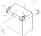
図1は、実施の形態に係る蓄電装置1の外観を示す斜視図である。図2は、実施の形態
に係る蓄電装置1の分解斜視図である。
FIG. 1 is a perspective view showing an external appearance of a power storage device 1 according to the embodiment. FIG. 2 is an exploded perspective view of power storage device 1 according to the embodiment.

なお、これらの図では、Z軸方向を上下方向として示しており、以下ではZ軸方向を上下方向として説明するが、使用態様によってはZ軸方向が上下方向にならない場合も考えられる。すなわち、Z軸方向は上下方向となることには限定されない。   In these figures, the Z-axis direction is shown as the up-down direction, and the Z-axis direction will be described below as the up-down direction. However, depending on the mode of use, the Z-axis direction may not be up-down. That is, the Z-axis direction is not limited to being the vertical direction.

蓄電装置1は、外部からの電気を充電し、また外部へ電気を放電することができる装置である。例えば、蓄電装置1は、電力貯蔵用途や電源用途などに使用される電池モジュールである。   The power storage device 1 is a device that can charge electricity from the outside and discharge electricity to the outside. For example, the power storage device 1 is a battery module used for power storage use, power supply use, and the like.

これらの図に示すように、蓄電装置1は、外装体10を備える。本実施の形態では、図2に示すように、4つの蓄電素子100が外装体10に収容されている。なお、外装体10には、例えば、各蓄電素子100の状態を監視し制御する制御基板等の他の要素が収容されていてもよいが、これら他の要素についての図示及び説明は省略する。   As shown in these drawings, the power storage device 1 includes an exterior body 10. In the present embodiment, as shown in FIG. 2, four power storage elements 100 are accommodated in the exterior body 10. In addition, although other elements, such as a control board which monitors and controls the state of each electrical storage element 100, may be accommodated in the exterior body 10, illustration and description about these other elements are abbreviate | omitted.

外装体10は、矩形状(箱状)の容器(モジュールケース)であり、複数の蓄電素子100等の収容物を所定の位置に保持し、かつ、衝撃等から保護する役目を担う。外装体10は、例えば、ポリカーボネート(PC)またはポリプロピレン(PP)等の絶縁性の樹脂で形成される。   The outer package 10 is a rectangular (box-shaped) container (module case), and holds the contents such as the plurality of power storage elements 100 in a predetermined position and protects them from impacts and the like. The package 10 is formed of an insulating resin such as polycarbonate (PC) or polypropylene (PP).

具体的には、外装体10は、蓄電素子100を収容する本体12と、本体12の開口を塞ぐように配置された蓋体11とを有する。本体12の開口の周縁と、蓋体11の周縁とは、熱溶着等の手法によって気密が維持されるよう接合されている。   Specifically, the exterior body 10 includes a main body 12 that houses the power storage element 100 and a lid body 11 that is disposed so as to close the opening of the main body 12. The peripheral edge of the opening of the main body 12 and the peripheral edge of the lid 11 are joined so that airtightness is maintained by a technique such as thermal welding.

外装体10には、外装体10の内部と外部とを連通する通路を形成する排気部50が設けられている。外装体10の側面(本実施の形態では、蓋体11のY軸方向マイナス側の面)には、開口部52が形成されており、例えば、1以上の蓄電素子100からガスが放出された場合に、排気部50の開口部52から外装体10の外部にガスが排出される。排気部50の詳細については、図3及び図4を用いて後述する。   The exterior body 10 is provided with an exhaust portion 50 that forms a passage that communicates the inside and the exterior of the exterior body 10. An opening 52 is formed on the side surface of the exterior body 10 (in this embodiment, the surface on the negative side in the Y-axis direction of the lid body 11). For example, gas is released from one or more power storage elements 100. In this case, the gas is discharged from the opening 52 of the exhaust unit 50 to the outside of the exterior body 10. Details of the exhaust unit 50 will be described later with reference to FIGS. 3 and 4.

蓋体11は、外装体10の上面13を形成する部材であり、正極外部端子21と負極外部端子22とが設けられている。蓄電装置1は、この正極外部端子21と負極外部端子22とを介して、外部からの電気を充電し、また外部へ電気を放電する。   The lid 11 is a member that forms the upper surface 13 of the exterior body 10, and is provided with a positive external terminal 21 and a negative external terminal 22. The power storage device 1 charges electricity from the outside via the positive electrode external terminal 21 and the negative electrode external terminal 22, and discharges electricity to the outside.

また、本実施の形態では、正極外部端子21を形成する部分を含むバスバーと、負極外部端子22を形成する部分を含むバスバーとが、インサート成形によって、樹脂製の蓋体11に一体に設けられている。これにより、蓋体11の、2つの外部端子(21、22)が露出した部分における気密が維持されている。   In the present embodiment, the bus bar including the portion forming the positive external terminal 21 and the bus bar including the portion forming the negative external terminal 22 are integrally provided on the resin lid 11 by insert molding. ing. Thereby, the airtightness in the part which the two external terminals (21, 22) of the cover body 11 exposed is maintained.

ここで、本実施の形態では、4つの蓄電素子100は、図2に示すように、3つのバスバー30によって直列に接続されている。また、図2では図示されていないが、直列接続における両端の蓄電素子100の一方(図2では、Y軸方向で最もマイナス側の蓄電素子100)と、正極外部端子21とが電気的に接続されている。さらに、当該両端の蓄電素子100の他方(図2では、Y軸方向で最もプラス側の蓄電素子100)と、負極外部端子22とが電気的に接続されている。   Here, in the present embodiment, the four power storage elements 100 are connected in series by the three bus bars 30 as shown in FIG. Although not shown in FIG. 2, one of the power storage elements 100 at both ends in series connection (the power storage element 100 on the most negative side in the Y-axis direction in FIG. 2) and the positive electrode external terminal 21 are electrically connected. Has been. Furthermore, the other of the power storage elements 100 at both ends (the power storage element 100 on the most positive side in the Y-axis direction in FIG. 2) and the negative electrode external terminal 22 are electrically connected.

蓄電素子100は、電気を充電し、また、電気を放電することのできる二次電池(単電池)であり、より具体的には、リチウムイオン二次電池などの非水電解質二次電池である。蓄電素子100は、扁平形状の容器110と、容器110に配置された正極端子120及び負極端子130とを備える。なお、蓄電素子100は、非水電解質二次電池には限定されず、非水電解質二次電池以外の二次電池であってもよいし、キャパシタであってもよい。   The power storage element 100 is a secondary battery (unit cell) that can charge and discharge electricity, and more specifically, a non-aqueous electrolyte secondary battery such as a lithium ion secondary battery. . The power storage element 100 includes a flat container 110 and a positive electrode terminal 120 and a negative electrode terminal 130 disposed in the container 110. In addition, the electrical storage element 100 is not limited to a nonaqueous electrolyte secondary battery, A secondary battery other than a nonaqueous electrolyte secondary battery may be sufficient, and a capacitor may be sufficient as it.

蓄電素子100において、容器110の内部には、電極体200、電極体200と正極端子120とを接続する正極集電体、及び、電極体200と負極端子130とを接続する負極集電体が配置されている。また、容器110の内部には電解液などの液体が封入されている。なお、図2において、電極体200は、破線で描かれた直方体によって概念的に表されており、電極体200の形状及びサイズは、図2に示される形状およびサイズに限定されない。   In the electric storage element 100, inside the container 110, there are an electrode body 200, a positive electrode current collector that connects the electrode body 200 and the positive electrode terminal 120, and a negative electrode current collector that connects the electrode body 200 and the negative electrode terminal 130. Has been placed. In addition, a liquid such as an electrolytic solution is sealed inside the container 110. In FIG. 2, the electrode body 200 is conceptually represented by a rectangular parallelepiped drawn with a broken line, and the shape and size of the electrode body 200 are not limited to the shape and size shown in FIG. 2.

容器110は、金属からなる矩形筒状で底を備える容器本体と、容器本体の開口を閉塞する金属製の蓋板とで構成されている。容器110は、電極体200等を内部に収容後、蓋板と容器本体とが溶接等されることにより、内部を密封することができる構造を有している。   The container 110 is composed of a rectangular container made of metal and having a bottom, and a metal lid plate that closes the opening of the container body. The container 110 has a structure that can seal the inside by housing the electrode body 200 and the like and then welding the lid plate and the container body.

容器110の、電極端子(120、130)が配置された面にはガス排出弁170が備えられている。複数の蓄電素子100は、例えば図2に示されるように、各ガス排出弁170が、複数の蓄電素子100の並び方向(Y軸方向)に並ぶように配置される。   A gas discharge valve 170 is provided on the surface of the container 110 on which the electrode terminals (120, 130) are arranged. For example, as shown in FIG. 2, the plurality of power storage elements 100 are arranged such that the gas discharge valves 170 are arranged in the arrangement direction (Y-axis direction) of the plurality of power storage elements 100.

ガス排出弁170は、容器110の内圧が上昇した場合に開放し、容器110の内部のガスを排出する安全機構として、各蓄電素子100に備えられている。なお、蓄電装置1が備える複数の蓄電素子100の全てがガス排出弁170を備えていることには限定されず、少なくとも1つの蓄電素子100がガス排出弁170を備えていればよい。   The gas discharge valve 170 is opened when the internal pressure of the container 110 rises, and is provided in each power storage element 100 as a safety mechanism that discharges the gas inside the container 110. Note that not all of the plurality of power storage elements 100 included in the power storage device 1 include the gas discharge valve 170, and it is sufficient that at least one power storage element 100 includes the gas discharge valve 170.

蓄電素子100が有する電極体200は、例えば、正極と負極との間にセパレータが挟み込まれるように層状に配置されたものを巻回されて形成された巻回型の電極体200である。なお、電極体200は、巻回型には限定されず、例えば、平板状極板を積層した積層型の電極体200であってもかまわない。   The electrode body 200 included in the power storage element 100 is, for example, a wound electrode body 200 formed by winding a layered arrangement so that a separator is sandwiched between a positive electrode and a negative electrode. In addition, the electrode body 200 is not limited to a winding type, For example, the electrode body 200 may be a stacked electrode body 200 in which flat plate plates are stacked.

正極は、アルミニウムまたはアルミニウム合金などからなる長尺帯状の導電性の正極集電箔の表面に正極活物質層が形成された電極板である。負極は、銅または銅合金などからなる長尺帯状の導電性の負極集電箔の表面に負極活物質層が形成された電極板である。セパレータは、微多孔性のシートである。   The positive electrode is an electrode plate in which a positive electrode active material layer is formed on the surface of a long strip-like conductive positive electrode current collector foil made of aluminum or an aluminum alloy. The negative electrode is an electrode plate in which a negative electrode active material layer is formed on the surface of a long strip-like conductive negative electrode current collector foil made of copper or a copper alloy. The separator is a microporous sheet.

なお、蓄電素子100に用いられる正極、負極及びセパレータの材料としては、蓄電素子100の性能を損なうものでなければ適宜公知の材料を使用できる。また、容器110に封入される電解液(非水電解質)としても、蓄電素子100の性能を損なうものでなければその種類に特に制限はなく様々なものを選択することができる。   Note that as a material of the positive electrode, the negative electrode, and the separator used in the power storage element 100, known materials can be appropriately used as long as the performance of the power storage element 100 is not impaired. Further, the electrolyte solution (nonaqueous electrolyte) sealed in the container 110 is not particularly limited as long as it does not impair the performance of the power storage device 100, and various types can be selected.

正極端子120及び負極端子130は、容器110に収容された電極体200に蓄えられている電気を蓄電素子100の外部空間に導出し、また、電極体200に電気を蓄えるために蓄電素子100の内部空間に電気を導入するための金属製の電極端子である。   The positive electrode terminal 120 and the negative electrode terminal 130 lead out the electricity stored in the electrode body 200 accommodated in the container 110 to the external space of the power storage element 100, and also store the electricity in the electrode body 200 in order to store the electricity. It is a metal electrode terminal for introducing electricity into the internal space.

本実施の形態では、正極端子120及び負極端子130のそれぞれには、バスバーと接続するためのボルトが配置されており、ボルト及びナットによって、正極端子120及び負極端子130のそれぞれとバスバーとが締結される。なお、正極端子120及び負極端子130のそれぞれとバスバーとは、例えばレーザ溶接等の溶接によって接合されていてもよい。   In this embodiment, each of the positive terminal 120 and the negative terminal 130 is provided with a bolt for connecting to the bus bar, and the positive terminal 120 and the negative terminal 130 and the bus bar are fastened by the bolt and nut. Is done. In addition, each of the positive electrode terminal 120 and the negative electrode terminal 130 and the bus bar may be joined by welding such as laser welding.

上記構成を有する蓄電素子100は、本実施の形態では、仕切部材40に隣接して配置されている。つまり、外装体10には、複数の蓄電素子100のうちの隣り合う2つの蓄電素子100の間を仕切る仕切部材40が配置されている。この仕切部材40によって、例えば、蓄電素子100の位置規制、または、蓄電素子100の容器110同士の電気的な絶縁が図られる。   The electrical storage element 100 having the above configuration is disposed adjacent to the partition member 40 in the present embodiment. That is, the exterior body 10 is provided with a partition member 40 that partitions between two adjacent power storage elements 100 among the plurality of power storage elements 100. By this partition member 40, for example, position regulation of the power storage element 100 or electrical insulation between the containers 110 of the power storage element 100 is achieved.

なお、仕切部材40は、例えばPCまたはPP等の絶縁性の樹脂により形成されているが、絶縁性を有する素材であればどのような素材で形成されていてもかまわない。また、仕切部材40は、外装体10の本体12と一体に設けられていてもよく、外装体10の本体12とは別体の部品として作製され、本体12に後付けされてもよい。   The partition member 40 is formed of an insulating resin such as PC or PP, but may be formed of any material as long as it is an insulating material. Moreover, the partition member 40 may be provided integrally with the main body 12 of the exterior body 10, or may be manufactured as a separate component from the main body 12 of the exterior body 10 and may be retrofitted to the main body 12.

次に、本実施の形態に係る蓄電装置1の外装体10に備えられた排気部50について、図3〜図6を用いて説明する。   Next, the exhaust part 50 provided in the exterior body 10 of the power storage device 1 according to the present embodiment will be described with reference to FIGS.

図3は、実施の形態に係る排気部50の構成を示す断面図である。具体的には、図3では、図2におけるIII−III断面(一点鎖線を通るYZ平面における断面)の一部が図示されている。また、図3における点線は、通路54の軸(通路54を流体が通過する場合における流体の進行方向に沿った仮想線)を表している。   
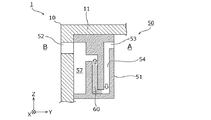
FIG. 3 is a cross-sectional view illustrating a configuration of the exhaust unit 50 according to the embodiment. Specifically, FIG. 3 shows a part of a section taken along the line III-III in FIG. 2 (a section in the YZ plane passing through the one-dot chain line). Also, the dotted line in FIG. 3 represents the axis of the passage 54 (virtual line along the fluid traveling direction when the fluid passes through the passage 54).

図1〜図3に示すように、外装体10には排気部50が設けられており、排気部50により、外装体10の内部と外部とを連通する通路54が形成されている。具体的には、本実施の形態では、図3に示すように、蓋体11の内面に通路形成部51が取り付けられている。通路形成部51は、蓋体11に形成された開口部52とともに、外装体10の内部空間Aと外部空間Bとを連通する通路54を形成している。なお、図3以降の図では、通路54の基本的な形状の一例が図示されており、通路54の形状、長さ、幅等の仕様は、図3に示される仕様には限定されない。   As shown in FIGS. 1 to 3, the exterior body 10 is provided with an exhaust portion 50, and the exhaust portion 50 forms a passage 54 that communicates the inside and the exterior of the exterior body 10. Specifically, in the present embodiment, as shown in FIG. 3, a passage forming portion 51 is attached to the inner surface of the lid body 11. The passage forming portion 51 forms a passage 54 that communicates the internal space A and the external space B of the exterior body 10 together with the opening 52 formed in the lid body 11. In FIG. 3 and subsequent figures, an example of the basic shape of the passage 54 is shown, and specifications such as the shape, length, and width of the passage 54 are not limited to the specifications shown in FIG.

通路形成部51は、例えば、外装体10と同じく、PCまたはPP等の絶縁性の樹脂で形成された部材であり、接着、溶着または締結等の手法により、蓋体11の内面に固定されている。通路形成部51では、上下方向に延設された複数の板部56が内部に配置されていることで、上下に蛇行した通路54が形成されている。すなわち、外装体10には、ラビリンス構造の排気部50が備えられている。   The passage forming portion 51 is a member formed of an insulating resin such as PC or PP, for example, like the exterior body 10, and is fixed to the inner surface of the lid 11 by a technique such as adhesion, welding, or fastening. Yes. In the passage forming portion 51, a plurality of plate portions 56 extending in the vertical direction are disposed inside, so that a passage 54 meandering up and down is formed. That is, the exterior body 10 is provided with an exhaust portion 50 having a labyrinth structure.

通路形成部51は、内部空間A側に開口部53を有しており、通路54は、内部空間A側の開口部53と、外部空間B側の開口部52とを接続するように形成されている。なお、通路54の、通路形成部51によって形成される部分の断面(軸に直交する断面)の形状に特に限定はないが、例えば円形または略円形である。   The passage forming part 51 has an opening 53 on the inner space A side, and the passage 54 is formed so as to connect the opening 53 on the inner space A side and the opening 52 on the outer space B side. ing. The shape of the cross section (cross section orthogonal to the axis) of the portion formed by the passage forming portion 51 of the passage 54 is not particularly limited, but is, for example, circular or substantially circular.

このような構造の排気部50は、通路54内において、通路54を塞ぐように配置された状態を維持しながら少なくとも一部が移動可能な移動部材60を有する。具体的には、内部空間Aまたは外部空間Bの圧力の上昇または減少(つまり、外装体10の内外の圧力差の変動)に伴い、移動部材60の少なくとも一部は、通路54内を移動する。より具体的には、移動部材60の少なくとも一部が通路54内で移動することで、通路54を開放状態(流体の通過が可能な状態)にすることが可能である。   The exhaust part 50 having such a structure includes a moving member 60 that can move at least partially in the passage 54 while maintaining a state of being disposed so as to close the passage 54. Specifically, at least a part of the moving member 60 moves in the passage 54 as the pressure in the internal space A or the external space B increases or decreases (that is, the pressure difference inside and outside the exterior body 10). . More specifically, at least a part of the moving member 60 moves in the passage 54, so that the passage 54 can be in an open state (a state in which fluid can pass).

本実施の形態では、移動部材60として、通路54を塞ぐ液体が採用されている。具体的には、通路54の軸方向の一部(通路54の長手方向の一部)が、液体である移動部材60によって塞がれている。つまり、通路54は通常時において液封された状態である。   In the present embodiment, a liquid that closes the passage 54 is employed as the moving member 60. Specifically, a part of the passage 54 in the axial direction (a part of the passage 54 in the longitudinal direction) is blocked by the moving member 60 that is a liquid. That is, the passage 54 is in a liquid-sealed state at the normal time.

移動部材60として採用される液体としては、例えば、油分を含む、所定の粘性を有する液体が採用される。例えば、一般に油圧装置に動力伝達媒体として用いられる作動油が、移動部材60として排気部50に配置される。このような作動油としては、リン酸エステル系作動油などの難燃性の作動油が例示される。このような作動油は、揮発性が低いため、これにより、例えば移動部材60の長寿命化が図られる。   As the liquid employed as the moving member 60, for example, a liquid having a predetermined viscosity including oil is employed. For example, hydraulic oil that is generally used as a power transmission medium in a hydraulic device is disposed as a moving member 60 in the exhaust unit 50. Examples of such hydraulic oil include flame retardant hydraulic oil such as phosphate ester hydraulic oil. Since such hydraulic oil has low volatility, for example, the life of the moving member 60 can be extended.

なお、上記の移動部材60が有する所定の粘性とは、例えば、通常時における外装体10の内外の差圧によって移動部材60が通路54内を移動可能であり、かつ、蓄電装置1が傾けられた場合などにおいて、移動部材60が自重で排気部50から流出しない程度の粘性である。また、当該所定の粘性を決定するに際し、通路54の軸に直交する断面の断面積等も考慮される。または、当該所定の粘性が決定された後に、上記の条件(移動部材60が通路54内を移動可能、かつ、移動部材60が自重で排気部50から流出しない)を満たすように通路54の軸に直交する断面の断面積等が決定されてもよい。   The predetermined viscosity of the moving member 60 is, for example, that the moving member 60 can move in the passage 54 due to a differential pressure inside and outside the exterior body 10 in a normal state, and the power storage device 1 is tilted. In such a case, the viscosity of the moving member 60 is such that the moving member 60 does not flow out of the exhaust part 50 due to its own weight. Further, in determining the predetermined viscosity, a cross-sectional area of a cross section orthogonal to the axis of the passage 54 is also taken into consideration. Alternatively, after the predetermined viscosity is determined, the shaft of the passage 54 satisfies the above condition (the moving member 60 can move in the passage 54 and the moving member 60 does not flow out of the exhaust part 50 due to its own weight). The cross-sectional area of the cross section orthogonal to the cross section may be determined.

具体的には、本実施の形態に係る蓄電装置1は、例えばオートバイの始動用のバッテリーとして用いることが可能である。そのため、オートバイの転倒等の際に、移動部材60が排気部50から流出しないように、移動部材60である液体の粘性、並びに、通路54のサイズ及び形状等が決定されてもよい。   Specifically, power storage device 1 according to the present embodiment can be used as, for example, a battery for starting a motorcycle. Therefore, the viscosity of the liquid that is the moving member 60 and the size and shape of the passage 54 may be determined so that the moving member 60 does not flow out of the exhaust part 50 when the motorcycle falls.

また、移動部材60は、蓄電素子100が有する電解液が気化することで生じるガスに触れる可能性があるため、例えば、電解液に含まれる有機溶剤等に対する科学的な耐性を有していることが好ましい。   In addition, since the moving member 60 may come into contact with the gas generated when the electrolytic solution of the electricity storage device 100 is vaporized, it has scientific resistance to, for example, an organic solvent contained in the electrolytic solution. Is preferred.

また、本実施の形態では、図3に示すように、排気部50が有する通路54は、トラップ構造により移動部材60を貯留する貯留部55を含んでいる。つまり、貯留部55は、通路54が下向きから上向きに折り返した部分(下った後に上がっている部分)によって形成されている。また、移動部材60が貯留部55に貯留されている状態では、通路54は移動部材60によって封止された状態である。なお、貯留部55を構成する通路54の形状は、図3に示す形状には限定されず、U字状またはV字状など、移動部材60を貯留可能な形状であればよい。貯留部55は、通常時において、移動部材60を通路54内の所定の位置にとどめる機能を有する。これにより、例えば、通常時における移動部材60の排気部50からの漏れ出し等が抑制される。   Moreover, in this Embodiment, as shown in FIG. 3, the channel | path 54 which the exhaust part 50 has includes the storage part 55 which stores the moving member 60 by a trap structure. That is, the storage portion 55 is formed by a portion where the passage 54 is folded upward from the downward direction (the portion that is raised after being lowered). In a state where the moving member 60 is stored in the storage portion 55, the passage 54 is sealed by the moving member 60. In addition, the shape of the channel | path 54 which comprises the storage part 55 is not limited to the shape shown in FIG. 3, What is necessary is just the shape which can store the moving member 60, such as U shape or V shape. The storage unit 55 has a function of keeping the moving member 60 at a predetermined position in the passage 54 at the normal time. Thereby, for example, leakage from the exhaust part 50 of the moving member 60 at the normal time is suppressed.

このように構成された排気部50において、外装体10の内外の圧力差の変動に応じて、通路54内において移動部材60が移動する。このことを、図4及び図5を用いて説明する。   In the exhaust portion 50 configured as described above, the moving member 60 moves in the passage 54 in accordance with the fluctuation of the pressure difference between the inside and outside of the exterior body 10. This will be described with reference to FIGS.

図4は、外装体10の内圧が外圧よりも大きい場合における排気部50の状態を示す図であり、図5は、外装体10の外圧が内圧よりも大きい場合における排気部50の状態を示す図である。   FIG. 4 is a diagram showing the state of the exhaust part 50 when the internal pressure of the exterior body 10 is larger than the external pressure, and FIG. 5 shows the state of the exhaust part 50 when the external pressure of the exterior body 10 is larger than the internal pressure. FIG.

例えば、外装体10の内部の温度が上昇すること、または、蓄電装置1の周囲の気圧が下がること等に起因して、外装体10の内圧が外圧よりも大きくなった場合、移動部材60は、通路54内を、外装体10の外部側(開口部52の方向)に移動する。なお、蓄電装置1の周囲の気圧の上下は、例えば、蓄電装置1が配置された場所における天候の変化のほか、蓄電装置1の輸送時における高度の変化等に起因して生じる。   For example, when the internal pressure of the exterior body 10 becomes larger than the external pressure due to an increase in the temperature inside the exterior body 10 or a decrease in atmospheric pressure around the power storage device 1, the moving member 60 is The inside of the passage 54 is moved to the outside of the exterior body 10 (in the direction of the opening 52). Note that the rise and fall of the atmospheric pressure around the power storage device 1 occurs due to, for example, a change in weather at the place where the power storage device 1 is disposed, an altitude change during transportation of the power storage device 1, and the like.

具体的には、外装体10の内外の圧力差Pd1(Pd1=内圧−外圧>0)の増加に伴い、圧力差Pd1が、移動部材60を外装体10の外部側の開口部52の方向に押す(または引っ張る)力として作用し、通路54内における移動部材60の移動が開始する。その後、移動部材60が開口部52の方向に移動することで、外装体10の内部空間Aの容積が、通路54内における移動部材60の移動距離に応じた容積だけ増加する。これにより、外装体10の内圧が低下し、外装体10の内外の圧力が実質的に平衡する。その結果、移動部材60は例えば図4に示す位置で停止する。この場合であっても、移動部材60が通路54を塞ぐ状態は維持される。   Specifically, as the pressure difference Pd1 inside and outside the exterior body 10 increases (Pd1 = internal pressure−external pressure> 0), the pressure difference Pd1 causes the moving member 60 to move toward the opening 52 on the outside of the exterior body 10. Acting as a pushing (or pulling) force, the movement of the moving member 60 in the passage 54 starts. Thereafter, the moving member 60 moves in the direction of the opening 52, whereby the volume of the internal space A of the exterior body 10 increases by a volume corresponding to the moving distance of the moving member 60 in the passage 54. Thereby, the internal pressure of the exterior body 10 falls, and the internal and external pressures of the exterior body 10 are substantially balanced. As a result, the moving member 60 stops at, for example, the position shown in FIG. Even in this case, the state in which the moving member 60 blocks the passage 54 is maintained.

また、例えば、蓄電装置1の周囲の気温または気圧が上がること等に起因して、外装体10の外圧が内圧よりも大きくなった場合、移動部材60は、通路54内を、外装体10の内部側(開口部53の方向)に移動する。   For example, when the external pressure of the exterior body 10 becomes larger than the internal pressure due to, for example, an increase in temperature or pressure around the power storage device 1, the moving member 60 moves inside the passage 54 in the exterior body 10. Move to the inside (in the direction of the opening 53).

具体的には、外装体10の内外の圧力差Pd2(Pd2=外圧−内圧>0)の増加に伴い、圧力差Pd2が、移動部材60を外装体10の内部側の開口部53の方向に押す(または引っ張る)力として作用し、通路54内における移動部材60の移動が開始する。その後、移動部材60が開口部53の方向に移動することで、外装体10の内部空間Aの容積が、通路54内における移動部材60の移動距離に応じた容積だけ減少する。これにより、外装体10の内圧が増加し、外装体10の内外の圧力が実質的に平衡する。その結果、移動部材60は例えば図5に示す位置で停止する。この場合であっても、移動部材60が通路54を塞ぐ状態は維持される。   Specifically, as the pressure difference Pd2 inside and outside the exterior body 10 increases (Pd2 = external pressure−internal pressure> 0), the pressure difference Pd2 causes the moving member 60 to move toward the opening 53 on the inside of the exterior body 10. Acting as a pushing (or pulling) force, the movement of the moving member 60 in the passage 54 starts. Thereafter, the moving member 60 moves in the direction of the opening 53, whereby the volume of the internal space A of the exterior body 10 decreases by a volume corresponding to the moving distance of the moving member 60 in the passage 54. Thereby, the internal pressure of the exterior body 10 increases, and the pressure inside and outside the exterior body 10 is substantially balanced. As a result, the moving member 60 stops at the position shown in FIG. 5, for example. Even in this case, the state in which the moving member 60 blocks the passage 54 is maintained.

なお、図4及び図5では、移動部材60の全体が移動しているが、移動部材60の一部のみが通路54の軸方向に移動すること、つまり、移動部材60の通路54の軸方向の長さが伸縮することで、外装体10の内外の圧力差を吸収することは可能である。すなわち、本実施の形態では、移動部材60は作動油等の液体である。そのため、移動部材60は、全体として移動しない場合であっても、通路54を塞いだ状態を維持しながら、一部が移動(長さが伸縮)することは可能である。   4 and 5, the entire moving member 60 is moving, but only a part of the moving member 60 moves in the axial direction of the passage 54, that is, the axial direction of the passage 54 of the moving member 60. It is possible to absorb the pressure difference between the inside and outside of the exterior body 10 by extending and contracting the length of the outer casing 10. That is, in the present embodiment, the moving member 60 is a liquid such as hydraulic oil. Therefore, even if the moving member 60 does not move as a whole, a part of the moving member 60 can move (length can be expanded and contracted) while maintaining the state where the passage 54 is closed.

このように、蓄電装置1の周囲の環境の変化、または、蓄電装置1の使用時における発熱等に起因して、外装体10の内外の圧力差が変動した場合、外装体10の内外の圧力を平衡させるように、移動部材60が、通路54を塞いだ状態を維持しながら通路54内を移動する。これにより、例えば、外装体10の内外の圧力差が変動すること、または変動が繰り返すことによる破壊または劣化等の不具合が、排気部50を含む外装体10に生じ難い。   As described above, when the pressure difference between the inside and outside of the exterior body 10 fluctuates due to a change in the environment around the power storage device 1 or heat generation when the power storage device 1 is used, the pressure inside and outside the exterior body 10 is changed. The moving member 60 moves in the passage 54 so as to keep the passage 54 closed. Thereby, for example, the exterior body 10 including the exhaust part 50 is unlikely to have a problem such as destruction or deterioration due to fluctuations in the pressure difference between the inside and outside of the exterior body 10 or repeated fluctuations.

また、何らかの要因により、外装体10に収容された1以上の蓄電素子100のガス排出弁170が開放してガスが排出された場合、外装体10の内圧は急激に上昇し、排気部50の通路54内における移動部材60の移動だけでは内圧の上昇を吸収できない状態が生ずる。この場合、外装体10の内部のガスは、排気部50を介して外装体10の外部に放出される。   Further, when the gas discharge valve 170 of one or more power storage elements 100 accommodated in the exterior body 10 is opened and the gas is exhausted for some reason, the internal pressure of the exterior body 10 rapidly increases, A state in which the increase of the internal pressure cannot be absorbed only by the movement of the moving member 60 in the passage 54 occurs. In this case, the gas inside the exterior body 10 is released to the outside of the exterior body 10 through the exhaust part 50.

図6は、外装体10の内部のガスを外部に放出する際の排気部50の状態を示す図である。   FIG. 6 is a diagram illustrating a state of the exhaust unit 50 when the gas inside the exterior body 10 is released to the outside.

蓄電装置1において、1以上の蓄電素子100のガス排出弁170が開放するなどにより、外装体10内部で大量のガスが発生した場合、通路54内の移動部材60は、外装体10の内圧に押されて、外装体10の外部側の開口部52の方向に移動する。   In the power storage device 1, when a large amount of gas is generated inside the exterior body 10 due to, for example, opening of the gas discharge valve 170 of one or more power storage elements 100, the moving member 60 in the passage 54 becomes the internal pressure of the exterior body 10. It is pushed and moves in the direction of the opening 52 on the outside of the exterior body 10.

ここで、本実施の形態に係る排気部50は、移動部材60を収容可能な空間を形成する収容部57を有している。収容部57は、貯留部55と開口部52との間の位置において通路54と接続されている。そのため、開口部52に向けて移動した移動部材60は、開口部52に到達する前に、図6に示すように、開口部52よりも下方に位置する収容部57の方向に向かう。その結果、移動部材60は収容部57に収容される。また、移動部材60が収容部57に逃げる(通路54から外れる)ことにより、通路54が開放状態となり、その結果、外装体10の内部のガスは、開口部52から外装体10の外部に放出される。これにより、外装体10の内圧の上昇は抑制され、例えば、外装体10の内圧が過大になるとによる外装体10の破壊等の可能性が低減される。   Here, the exhaust part 50 according to the present embodiment has a housing part 57 that forms a space in which the moving member 60 can be housed. The accommodating portion 57 is connected to the passage 54 at a position between the storage portion 55 and the opening portion 52. Therefore, the moving member 60 that has moved toward the opening 52 is directed toward the accommodating portion 57 located below the opening 52 as shown in FIG. 6 before reaching the opening 52. As a result, the moving member 60 is accommodated in the accommodating portion 57. Further, when the moving member 60 escapes to the accommodating portion 57 (disengages from the passage 54), the passage 54 is opened, and as a result, the gas inside the exterior body 10 is released from the opening 52 to the outside of the exterior body 10. Is done. Thereby, the rise in the internal pressure of the exterior body 10 is suppressed, and for example, the possibility of destruction of the exterior body 10 due to an excessive internal pressure of the exterior body 10 is reduced.

以上説明したように、本実施の形態に係る蓄電装置1は、外装体10を備える。外装体10には、外装体10の内部と外部とを連通する通路54を形成する排気部50が設けられている。排気部50は、通路54内において、通路54を塞ぐように配置された状態を維持しながら少なくとも一部が移動可能な移動部材60を有する。   As described above, power storage device 1 according to the present embodiment includes exterior body 10. The exterior body 10 is provided with an exhaust portion 50 that forms a passage 54 that communicates the interior and exterior of the exterior body 10. The exhaust unit 50 includes a moving member 60 that can move at least partially in the passage 54 while maintaining a state of being disposed so as to close the passage 54.

この構成によれば、例えば、蓄電素子100のガス排出弁170からガスが排出されるような異常が発生した場合、そのガスを、排気部50の通路54を介して外装体10の外部に導くことができる。これにより、異常時における外装体10の内圧の上昇が抑制される。また、通路54を塞ぐように移動部材60が配置されるため、外装体10の外部から内部への通路54を介した水分(水滴、湿気など)の流入が抑制される。さらに、移動部材60の少なくとも一部が移動可能である。つまり、移動部材60は、例えば通常時における外装体10の内外の圧力差を吸収するように動作することができる。そのため、例えば、当該圧力差の変動の繰り返しに起因して、移動部材60等の構成要素が破断または破壊される事態が生じ難い。これにより、例えば通常時における環境の変化等に起因して、通路54が開放状態になる可能性が低減される。このように、本実施の形態に係る蓄電装置1は、安全性が向上された蓄電装置1である。   According to this configuration, for example, when an abnormality occurs such that the gas is discharged from the gas discharge valve 170 of the power storage element 100, the gas is guided to the outside of the exterior body 10 through the passage 54 of the exhaust unit 50. be able to. Thereby, the raise of the internal pressure of the exterior body 10 at the time of abnormality is suppressed. Further, since the moving member 60 is disposed so as to block the passage 54, the inflow of moisture (water droplets, moisture, etc.) from the outside to the inside of the exterior body 10 through the passage 54 is suppressed. Furthermore, at least a part of the moving member 60 is movable. That is, the moving member 60 can operate so as to absorb, for example, a pressure difference between the inside and outside of the exterior body 10 at a normal time. Therefore, for example, it is difficult for a component such as the moving member 60 to be broken or broken due to repeated fluctuations in the pressure difference. Thereby, for example, due to environmental changes during normal times, the possibility of the passage 54 being in an open state is reduced. Thus, power storage device 1 according to the present embodiment is power storage device 1 with improved safety.

また、本実施の形態において、移動部材60は、通路54を塞ぐ液体である。移動部材60として液体を採用することで、例えば、移動部材60は、通路54を塞ぎつつ通路54内でスムーズに移動することができる。つまり、通路54を介した外装体10の内部へ湿気の流入を抑制しながら、移動部材60による外装体10の内外の圧力差の吸収が効率よく行われる。また、移動部材60として粘性の高い液体を選択することで、通常時における移動部材60の排気部50からの漏れ出しが抑制される。また、移動部材60として油分を含む液体を選択することで、移動部材60による、湿気の流入抑制効果(防湿効果)が向上される。さらに、移動部材60として揮発性の低い液体を選択することで、例えば移動部材60の長寿命化が図られる。   In the present embodiment, the moving member 60 is a liquid that blocks the passage 54. By employing a liquid as the moving member 60, for example, the moving member 60 can move smoothly in the passage 54 while closing the passage 54. In other words, the pressure difference between the inside and outside of the exterior body 10 is efficiently absorbed by the moving member 60 while suppressing the inflow of moisture into the exterior body 10 through the passage 54. Further, by selecting a highly viscous liquid as the moving member 60, leakage from the exhaust part 50 of the moving member 60 during normal operation is suppressed. Further, by selecting a liquid containing oil as the moving member 60, the moisture inflow suppressing effect (moisture-proofing effect) by the moving member 60 is improved. Furthermore, by selecting a low-volatile liquid as the moving member 60, for example, the life of the moving member 60 can be extended.

また、本実施の形態において、通路54は、トラップ構造により移動部材60を貯留する貯留部55を含んでいる。つまり、貯留部55は、例えば、通路54が下向きから上向きに折り返した部分によって形成されるため、通路54そのものの形状による、水分の外装体10の内部への流入抑制効果を得ることができる。また、移動部材60を貯留部55に配置することで、例えば、蓄電装置1が傾けられた場合における移動部材60の排気部50からの飛び出しまたは漏れ出しを抑制することができる。   Moreover, in this Embodiment, the channel | path 54 contains the storage part 55 which stores the moving member 60 by a trap structure. That is, the reservoir 55 is formed by, for example, a portion where the passage 54 is folded upward from the downward direction, so that the effect of suppressing the inflow of moisture into the exterior body 10 by the shape of the passage 54 itself can be obtained. Further, by disposing the moving member 60 in the storage unit 55, for example, jumping out or leakage of the moving member 60 from the exhaust unit 50 when the power storage device 1 is tilted can be suppressed.

また、本実施の形態に係る排気部50はさらに、移動部材60を収容可能な空間を形成する収容部57を有する。収容部57は、通路54の移動部材60が配置された位置(本実施の形態では貯留部55)と、通路54の外部側の開口部52との間の位置において、通路54と接続されている。   Further, the exhaust part 50 according to the present embodiment further includes a storage part 57 that forms a space in which the moving member 60 can be stored. The accommodating portion 57 is connected to the passage 54 at a position between the position where the moving member 60 of the passage 54 is disposed (the storage portion 55 in this embodiment) and the opening 52 on the outside of the passage 54. Yes.

つまり、通路54に接続された収容部57が、移動部材60から見て、通路54の外部側の出口(開口部52)より手前の位置に配置される。これにより、例えば、外装体10の内部で発生したガスの圧力によって通路54内を移動する移動部材60を収容部57に導き、かつ、当該ガスを、外装体10の外部に導くことができる。そのため、例えば、外装体10の内部で大量にガスが発生した場合に、当該ガスとともに移動部材60が外装体10の外部に排出される可能性が低減される。その結果、例えば、移動部材60が、外装体10の外部の熱源と接触すること等に起因する不具合の発生が抑制される。   That is, the accommodating portion 57 connected to the passage 54 is disposed at a position in front of the outlet (opening portion 52) on the outside of the passage 54 when viewed from the moving member 60. Thereby, for example, the moving member 60 that moves in the passage 54 by the pressure of the gas generated inside the exterior body 10 can be guided to the housing portion 57, and the gas can be guided outside the exterior body 10. Therefore, for example, when a large amount of gas is generated inside the exterior body 10, the possibility that the moving member 60 is discharged to the outside of the exterior body 10 together with the gas is reduced. As a result, for example, the occurrence of problems caused by the moving member 60 coming into contact with a heat source outside the exterior body 10 is suppressed.

ここで、蓄電装置1は、図3〜図6に示す排気部50とは異なる構成の排気部を備えてもよい。そこで、以下に、実施の形態に係る排気部50に関する変形例を、上記実施の形態との差分を中心に説明する。   Here, the power storage device 1 may include an exhaust unit having a configuration different from that of the exhaust unit 50 illustrated in FIGS. 3 to 6. Therefore, in the following, a modified example related to the exhaust unit 50 according to the embodiment will be described focusing on differences from the above embodiment.

(変形例1)
図7は、実施の形態の変形例1に係る排気部50aの構成を示す断面図である。図7に示すように、外装体10には排気部50aが設けられている。排気部50aは、蓋体11の内面に通路形成部51aが取り付けられることで構成されており、外装体10の内部と外部とを連通する通路54を有している。この構造において、本変形例に係る排気部50aは、上記実施の形態に係る排気部50と共通する。
(Modification 1)
FIG. 7 is a cross-sectional view illustrating a configuration of an exhaust unit 50a according to the first modification of the embodiment. As shown in FIG. 7, the exterior body 10 is provided with an exhaust part 50a. The exhaust part 50 a is configured by attaching a passage forming part 51 a to the inner surface of the lid body 11, and has a passage 54 that communicates the inside and the outside of the exterior body 10. In this structure, the exhaust part 50a according to this modification is common to the exhaust part 50 according to the above embodiment.

本変形例に係る排気部50aが有する通路54は、通路54の軸方向に直交する断面の面積が他の部分よりも小さな幅狭部59を含んでいる。つまり、通路54内における物体の移動を阻害する構成要素として幅狭部59が設けられている。   The passage 54 included in the exhaust portion 50a according to the present modification includes a narrow portion 59 in which the cross-sectional area perpendicular to the axial direction of the passage 54 is smaller than that of the other portions. That is, the narrow portion 59 is provided as a component that hinders the movement of the object in the passage 54.

これにより、例えば、移動部材60の排気部50aからの飛び出しまたは漏れ出しを抑制する効果が得られる。より詳細には、本変形例では、幅狭部59は、通路54の開口部53の近傍に配置されている。これにより、移動部材60の、外装体10の内部への飛び出しまたは漏れ出しが抑制される。   Thereby, for example, an effect of suppressing jumping out or leakage from the exhaust part 50a of the moving member 60 is obtained. More specifically, in the present modification, the narrow portion 59 is disposed in the vicinity of the opening 53 of the passage 54. Thereby, the jumping out or leakage of the moving member 60 into the exterior body 10 is suppressed.

なお、幅狭部59は、通路54の開口部52の近傍に配置されていてもよい。つまり、幅狭部59が、通路54の両端のいずれか一方の近傍に配置されていることで、移動部材60は、通路54の軸方向において比較的に広い範囲で幅狭部59に阻害されずに移動することができる。つまり、通常時における外装体10の内外の圧力差が比較的に大きい場合であっても、その圧力差を移動部材60が移動することによって吸収することができ、かつ、幅狭部59による移動部材60の飛び出しまたは漏れ出しの抑制効果が得られる。   Note that the narrow portion 59 may be disposed in the vicinity of the opening 52 of the passage 54. That is, since the narrow portion 59 is disposed in the vicinity of either one of both ends of the passage 54, the moving member 60 is inhibited by the narrow portion 59 in a relatively wide range in the axial direction of the passage 54. You can move without That is, even when the pressure difference between the inside and outside of the exterior body 10 in a normal state is relatively large, the pressure difference can be absorbed by the movement of the moving member 60, and the movement by the narrow portion 59. The effect of suppressing the protrusion or leakage of the member 60 is obtained.

(変形例2)
図8は、実施の形態の変形例2に係る排気部50bの構成を示す断面図である。図8に示すように、外装体10には排気部50bが設けられており、排気部50bは、蓋体11の内面に通路形成部51bが取り付けられることで構成されている。また、排気部50bは、外装体10の内部と外部とを連通する通路54を有し、通路54の開口部52の近くに収容部57が接続されている。この構造において、本変形例に係る排気部50bは、上記実施の形態に係る排気部50と共通する。本変形例に係る排気部50bは、外装体10の内部側に収容部57aが配置されている点に特徴を有する。
(Modification 2)
FIG. 8 is a cross-sectional view illustrating a configuration of an exhaust unit 50b according to the second modification of the embodiment. As shown in FIG. 8, the exterior body 10 is provided with an exhaust portion 50 b, and the exhaust portion 50 b is configured by attaching a passage forming portion 51 b to the inner surface of the lid body 11. Further, the exhaust part 50 b has a passage 54 that communicates the inside and the outside of the exterior body 10, and a housing part 57 is connected near the opening 52 of the passage 54. In this structure, the exhaust part 50b according to this modification is common to the exhaust part 50 according to the above embodiment. The exhaust part 50b according to the present modification is characterized in that the accommodating part 57a is disposed on the inner side of the exterior body 10.

つまり、本変形例に係る排気部50bは、移動部材60を収容可能な空間を形成する収容部57aを有し、収容部57aは、通路54の移動部材60が配置された位置(本変形例における貯留部55)と、通路54の内部側の開口部53との間の位置において、通路54と接続されている。   That is, the exhaust part 50b according to the present modification has a housing part 57a that forms a space in which the moving member 60 can be housed, and the housing part 57a is located at a position where the moving member 60 is disposed in the passage 54 (this modified example). In the position between the storage portion 55) and the opening 53 on the inner side of the passage 54, the passage 54 is connected.

これにより、例えば、外装体10の内外の圧力差Pd2(Pd2=外圧−内圧>0)が極端に大きくなった場合、移動部材60を収容部57aに逃がすことで、移動部材60の、外装体10の内部への漏れ出しが抑制される。   Thereby, for example, when the pressure difference Pd2 between the inside and outside of the exterior body 10 (Pd2 = external pressure−internal pressure> 0) becomes extremely large, the exterior body of the travel member 60 is released by letting the travel member 60 escape to the accommodating portion 57a. Leakage into the interior of 10 is suppressed.

これにより、例えば、所定の粘性を有する液体である移動部材60が、外装体10の内部の導電部材に接触することに起因する短絡等の不具合の発生が抑制される。   Thereby, for example, the occurrence of problems such as a short circuit due to the moving member 60 being a liquid having a predetermined viscosity coming into contact with the conductive member inside the exterior body 10 is suppressed.

(変形例3)
図9は、実施の形態の変形例3に係る排気部150の構成を示す断面図である。図10は、実施の形態の変形例3に係る通路形成部151の構成を示す斜視図である。なお、図10では、通路形成部151の内部の構造物を破線で表し、かつ、移動部材60をドットで表している。
(Modification 3)
FIG. 9 is a cross-sectional view illustrating a configuration of an exhaust unit 150 according to Modification 3 of the embodiment. FIG. 10 is a perspective view showing a configuration of a passage forming portion 151 according to Modification 3 of the embodiment. In addition, in FIG. 10, the structure inside the channel | path formation part 151 is represented by the broken line, and the moving member 60 is represented by the dot.

図9に示すように、外装体10には排気部150が設けられており、排気部150は、蓋体11の内面に通路形成部151が取り付けられることで構成されている。また、排気部150は外装体10の内部と外部とを連通する通路154を有している。通路154は、トラップ構造により移動部材60を貯留する貯留部155を有する。   As shown in FIG. 9, the exterior body 10 is provided with an exhaust portion 150, and the exhaust portion 150 is configured by attaching a passage forming portion 151 to the inner surface of the lid body 11. Further, the exhaust part 150 has a passage 154 that communicates the inside and the outside of the exterior body 10. The passage 154 has a storage portion 155 that stores the moving member 60 by a trap structure.

排気部150は、上記構成を有することで、上記実施の形態に係る排気部50と同じく、例えば蓄電素子100のガス排出弁170から排出されたガスを、排気部150の通路154を介して外装体10の外部に導くことができる。また、移動部材60は、外装体10の内外の圧力差を吸収するように移動することができるため、例えば、当該圧力差の変動の繰り返しに起因して移動部材60等が破断または破壊される事態が生じ難い。   The exhaust unit 150 has the above-described configuration, so that, for example, the gas exhausted from the gas exhaust valve 170 of the power storage element 100 is externally disposed through the passage 154 of the exhaust unit 150, as in the exhaust unit 50 according to the above-described embodiment. It can be guided outside the body 10. Further, since the moving member 60 can move so as to absorb the pressure difference between the inside and outside of the exterior body 10, for example, the moving member 60 and the like are broken or broken due to repeated fluctuation of the pressure difference. It is hard to happen.

ここで、本変形例に係る排気部150では、外部側の開口部152と内部側の開口部153との間において、通路154を形成する内壁158に立設された、複数の板部156を有している。具体的には、通路形成部151は、図9に示す断面において、下側の内壁158に立設された2つの板部156と、上側の内壁158に立設された3つの板部156を有し、これにより、上記実施の形態に係る通路54よりも折り返し箇所が多い通路154が形成されている。つまり、排気部150において、開口部152と開口部153とを結ぶ直線に交差する姿勢で配置された5つの板部156によって、5つの折り返し箇所を有する通路154が形成されている。   Here, in the exhaust portion 150 according to the present modification, a plurality of plate portions 156 erected on the inner wall 158 forming the passage 154 between the outer opening portion 152 and the inner opening portion 153 are provided. Have. Specifically, in the cross section shown in FIG. 9, the passage forming portion 151 includes two plate portions 156 erected on the lower inner wall 158 and three plate portions 156 erected on the upper inner wall 158. Thus, a passage 154 having more folded portions than the passage 54 according to the above embodiment is formed. That is, in the exhaust part 150, a passage 154 having five turning points is formed by the five plate parts 156 arranged in a posture intersecting with a straight line connecting the opening part 152 and the opening part 153.

このように、通路形成部151は、直管形状の部材の内壁158に複数の板部156が配置された構造である。つまり、比較的に簡易な構造で、外装体10の外部から内部への水分の流入を抑制し、かつ、移動部材60の排気部150からの飛び出しまたは漏れ出しを抑制する形状の通路154が実現されている。   Thus, the channel | path formation part 151 is the structure where the some board part 156 was arrange | positioned in the inner wall 158 of a straight pipe-shaped member. In other words, the passage 154 is formed with a relatively simple structure that suppresses the inflow of moisture from the outside to the inside of the exterior body 10 and also prevents the moving member 60 from jumping out or leaking from the exhaust portion 150. Has been.

なお、本変形例に係る排気部150では、例えば、外装体10の内部の蓄電素子100のガス排出弁170からガスが排出された場合、当該ガスとともに移動部材60が外装体10の外部に排出される。しかし、この場合であっても、例えば、外装体10の外部に排出された移動部材60を受け取る容器を配置する等によって、移動部材60が外装体10の外部の要素に接触する可能性を低減させることができる。   In the exhaust unit 150 according to this modification, for example, when gas is discharged from the gas discharge valve 170 of the power storage element 100 inside the exterior body 10, the moving member 60 is discharged to the outside of the exterior body 10 together with the gas. Is done. However, even in this case, the possibility of the moving member 60 coming into contact with an element outside the exterior body 10 is reduced by, for example, arranging a container that receives the travel member 60 discharged outside the exterior body 10. Can be made.

また、本変形例では、排気部150は、5つの板部156を有するとしたが、排気部150は少なくとも1つの板部156を有すればよい。例えば、通路形成部151の上側の内壁158から下向きに立設された1つの板部156が存在する場合、上下方向の折り返し箇所を1つのみ有する通路154が形成される。この場合、通路154内に、例えば所定の粘性を有する液体である移動部材60を収容することで、通路154を移動部材60によって液封することは可能である。   In the present modification, the exhaust unit 150 includes the five plate portions 156. However, the exhaust unit 150 may include at least one plate unit 156. For example, in the case where there is one plate portion 156 erected downward from the inner wall 158 on the upper side of the passage forming portion 151, the passage 154 having only one folding portion in the vertical direction is formed. In this case, the passage 154 can be liquid-sealed by the moving member 60 by accommodating the moving member 60 that is, for example, a liquid having a predetermined viscosity in the passage 154.

また、図9では、排気部150は、全体が外装体10の内部に存在するように形成されているが、排気部150は、一部または全部が外装体10から突出するように形成されてもよい。   Further, in FIG. 9, the exhaust part 150 is formed so as to be entirely inside the exterior body 10, but the exhaust part 150 is formed so that part or all of the exhaust part 150 protrudes from the exterior body 10. Also good.

図11は、通路形成部151が外装体10の外側に配置されることで形成された排気部150の構成を示す断面図であり、図12は、通路形成部151が外装体10の貫通孔10aに嵌められることで形成された排気部150の構成を示す断面図である。   FIG. 11 is a cross-sectional view showing a configuration of the exhaust part 150 formed by arranging the passage forming part 151 outside the exterior body 10, and FIG. 12 is a through-hole of the exterior body 10 in the passage forming part 151. It is sectional drawing which shows the structure of the exhaust part 150 formed by being fitted by 10a.

図11に示す排気部150では、蓋体11の側面に通路形成部151が固定されており、蓋体11に形成された孔によって、通路154の外装体10の内部側の開口部153が形成されている。排気部150がこのように構成されている場合であっても、上述の、移動部材60による水分等の流入抑制機能等の、排気部150としての機能は失われない。また、排気部150は、外装体10の内部空間Aを消費することなく外装体10に設けられるため、外装体10の内部空間Aを、例えば蓄電容量の増加のためにより効率よく利用することができる。また、例えば、直管状の通路形成部151を、排気部150から排出されたガスを所定の位置まで導くためのパイプとの接続部(コネクタ)として利用することもできる。   In the exhaust part 150 shown in FIG. 11, the passage forming part 151 is fixed to the side surface of the lid 11, and the opening 153 inside the exterior body 10 of the passage 154 is formed by the hole formed in the lid 11. Has been. Even when the exhaust part 150 is configured in this way, the functions as the exhaust part 150 such as the above-described function of suppressing the inflow of moisture and the like by the moving member 60 are not lost. Moreover, since the exhaust part 150 is provided in the exterior body 10 without consuming the internal space A of the exterior body 10, it is possible to use the internal space A of the exterior body 10 more efficiently, for example, to increase the storage capacity. it can. Further, for example, the straight tubular passage forming portion 151 can be used as a connection portion (connector) with a pipe for guiding the gas discharged from the exhaust portion 150 to a predetermined position.

図12に示す排気部150は、蓋体11の側壁に設けられた貫通孔10aに通路形成部151が嵌められることで構成されている。また、通路形成部151の両端の孔によって、外装体10の外部側の開口部152及び外装体10の内部側の開口部153が形成されている。排気部150をこのように構成した場合であっても、上述の、移動部材60による水分等の流入抑機能等の、排気部150としての機能は失われない。また、排気部150は、一部が外装体10の内部に配置され、一部が外装体10の外部に配置される。そのため、例えば、排気部150による内部空間Aの消費量を抑制しつつ、外部に露出した通路形成部151を、外部のパイプとのコネクタとして利用することができる。   The exhaust part 150 shown in FIG. 12 is configured by fitting a passage forming part 151 into a through hole 10 a provided on the side wall of the lid 11. In addition, an opening 152 on the outer side of the exterior body 10 and an opening 153 on the inner side of the exterior body 10 are formed by holes at both ends of the passage forming portion 151. Even when the exhaust unit 150 is configured in this way, the functions as the exhaust unit 150 such as the function of suppressing the inflow of moisture and the like by the moving member 60 are not lost. Further, a part of the exhaust unit 150 is disposed inside the exterior body 10 and a part is disposed outside the exterior body 10. Therefore, for example, the passage forming portion 151 exposed to the outside can be used as a connector with an external pipe while suppressing consumption of the internal space A by the exhaust portion 150.

なお、排気部150の一部または全部が、外装体10から突出して設けられてもよい点については、上記の排気部50、50a、及び50bについても適用される。   In addition, it is applied also to said exhaust part 50, 50a, and 50b that the one part or all part of the exhaust part 150 may be protruded and provided from the exterior body 10. FIG.

(他の実施の形態)
以上、本発明に係る蓄電装置について、実施の形態及びその変形例に基づいて説明した。しかしながら、本発明は、上記実施の形態及びその変形例に限定されるものではない。本発明の趣旨を逸脱しない限り、当業者が思いつく各種変形を上記実施の形態またはその変形例に施したものも、あるいは、上記説明された複数の構成要素を組み合わせて構築される形態も、本発明の範囲内に含まれる。
(Other embodiments)
Heretofore, the power storage device according to the present invention has been described based on the embodiment and the modifications thereof. However, the present invention is not limited to the above-described embodiment and its modifications. As long as it does not deviate from the gist of the present invention, various modifications conceived by those skilled in the art may be applied to the above-described embodiment or its modifications, or a form constructed by combining a plurality of the constituent elements described above. Included within the scope of the invention.

例えば、上記実施の形態において、排気部50が有する通路54は、図3等の図面では、YZ平面内で折れ曲がった形状を有しているが、排気部50は立体的な通路54を有していてもよい。例えば、通路54は、YZ平面内で折れ曲がり、かつ、XY平面内で折れ曲がっていてもよい。つまり、通路54の形状は、より複雑化されてもよい。これにより、例えば、外装体10の外部から内部への通路54を介した水分の流入抑制効果が増大する。また、通路54の全長をより長くすることができるため、例えば、通常時における移動部材60の移動可能範囲が広がる。その結果、通常時における外装体10の内外の圧力差が比較的に大きい場合であっても、その圧力差を移動部材60が移動することによって吸収することができる。   For example, in the above-described embodiment, the passage 54 of the exhaust unit 50 has a bent shape in the YZ plane in the drawings such as FIG. 3, but the exhaust unit 50 has a three-dimensional passage 54. It may be. For example, the passage 54 may be bent in the YZ plane and may be bent in the XY plane. That is, the shape of the passage 54 may be more complicated. Thereby, for example, the effect of suppressing the inflow of moisture through the passage 54 from the outside to the inside of the exterior body 10 is increased. Moreover, since the full length of the channel | path 54 can be made longer, for example, the movable range of the moving member 60 in the normal time is expanded. As a result, even when the pressure difference between the inside and outside of the exterior body 10 at a normal time is relatively large, the pressure difference can be absorbed by the movement of the moving member 60.

また、例えば、上記実施の形態において、排気部50は、内部に1以上の蓄電素子100を収容する外装体10に設けられているが、排気部50は、蓄電素子の容器に設けられてもよい。つまり、排気部50、50a、50b、または150等の排気部は、蓄電素子において電極体及び電解液等を覆う外装体である容器に設けられてもよい。すなわち、「排気部50等の排気部が設けられた外装体を備える蓄電装置」は、外装体としての容器を備える蓄電素子として実現することもできる。   Further, for example, in the above embodiment, the exhaust part 50 is provided in the exterior body 10 that houses one or more power storage elements 100 therein, but the exhaust part 50 may be provided in a container of the power storage element. Good. That is, the exhaust part 50, 50a, 50b, or 150 may be provided in a container that is an exterior body that covers the electrode body, the electrolytic solution, and the like in the power storage element. That is, the “power storage device including an exterior body provided with an exhaust section such as the exhaust section 50” can also be realized as a power storage element including a container as the exterior body.

この場合、通常時では、排気部は、容器内の気密を維持する状態であり、かつ、電解液の気化が急激に進むような異常が生じた場合は、当該気化により生じたガスを排気部を介して蓄電素子の外部に放出することができる。つまり、蓄電素子において、排気部は、ガス排出弁と同様の効果を発揮することができ、かつ、蓄電素子の容器の内外圧の変動による破壊等の問題が生じ難い。   In this case, in normal times, the exhaust part is in a state of maintaining airtightness in the container, and when an abnormality occurs such that the evaporation of the electrolyte proceeds rapidly, the gas generated by the vaporization is discharged to the exhaust part. It can be discharged to the outside of the electricity storage element via That is, in the electricity storage element, the exhaust part can exhibit the same effect as the gas discharge valve, and problems such as destruction due to fluctuations in the internal and external pressures of the container of the electricity storage element hardly occur.

また、排気部50等が有する移動部材60は、所定の粘性を有する液体であるとした。しかし、排気部が有する移動部材は、固体または粉体でもよい。また、移動部材60は、液体、固体、及び粉体のうちの少なくとも2つの組み合わせによって形成されてもよい。   In addition, the moving member 60 included in the exhaust unit 50 or the like is a liquid having a predetermined viscosity. However, the moving member of the exhaust part may be solid or powder. Moreover, the moving member 60 may be formed of a combination of at least two of liquid, solid, and powder.

例えば、排気部が有する通路の断面形状が円である場合に、移動部材として、通路を塞ぐように配置することができる球体であって、かつ、通路内を移動可能な程度の大きさの球体が採用されてもよい。この場合、例えば、移動部材が液体である場合と異なり、移動部材が揮発することを考慮する必要がない。   For example, when the cross-sectional shape of the passage included in the exhaust portion is a circle, the moving member is a sphere that can be disposed so as to close the passage, and has a size that can move in the passage. May be adopted. In this case, for example, unlike the case where the moving member is a liquid, it is not necessary to consider that the moving member volatilizes.

また、排気部が外装体10の内部のガスを外部に放出する場合、移動部材の全体が移動する必要はない。例えば、外装体10の内部と外部とを連通する通路を塞ぐ移動部材が縮む(一部が移動する)ことで、当該通路を開放してもよい。つまり、排気部は、例えば、通常時では、弾性力を有する移動部材の伸縮によって外装体10の内外の圧力差を吸収し、かつ、異常時では、移動部材が縮むことで、外装体10の内部のガスを外部に放出するパス(通路)を形成してもよい。   Further, when the exhaust part releases the gas inside the outer package 10 to the outside, the entire moving member does not need to move. For example, the passage may be opened by contracting (partly moving) a moving member that closes the passage that connects the inside and the outside of the exterior body 10. In other words, for example, the exhaust part absorbs the pressure difference between the inside and outside of the exterior body 10 by expansion and contraction of the moving member having elasticity, and, at the time of abnormality, the exhaust member contracts, A path (passage) for releasing the internal gas to the outside may be formed.

また、例えば、排気部50を介したガスの排出が行われることで、移動部材60が収容部57(図3参照)内に移動した場合、例えば、スポイト等の道具によって収容部57から移動部材60を一旦吸い出して、貯留部55(図3参照)に注入してもよい。これにより、排気部50からガスが排出されたことにより破壊を免れた外装体10を再利用することができる。   Further, for example, when the moving member 60 moves into the accommodating portion 57 (see FIG. 3) by discharging the gas through the exhaust portion 50, for example, the moving member is moved from the accommodating portion 57 by a tool such as a dropper. 60 may be sucked out once and injected into the reservoir 55 (see FIG. 3). Thereby, the exterior body 10 which has escaped destruction due to the gas being discharged from the exhaust part 50 can be reused.

本発明は、蓄電素子、または、複数の蓄電素子を備える蓄電装置等に適用できる。   The present invention can be applied to a power storage element or a power storage device including a plurality of power storage elements.

1 蓄電装置
10 外装体
10a 貫通孔
11 蓋体
12 本体
13 上面
21 正極外部端子
22 負極外部端子
30 バスバー
40 仕切部材
50、50a、50b、150 排気部
51、51a、51b、151 通路形成部
52、53、152、153 開口部
54、154 通路
55、155 貯留部
56、156 板部
57、57a 収容部
59 幅狭部
60 移動部材
100 蓄電素子
110 容器
120 正極端子
130 負極端子
158 内壁
170 ガス排出弁
200 電極体
DESCRIPTION OF SYMBOLS 1 Power storage device 10 Exterior body 10a Through-hole 11 Lid body 12 Main body 13 Upper surface 21 Positive electrode external terminal 22 Negative electrode external terminal 30 Bus bar 40 Partition member 50, 50a, 50b, 150 Exhaust part 51, 51a, 51b, 151 Passage formation part 52, 53, 152, 153 Opening 54, 154 Passage 55, 155 Reserving part 56, 156 Plate part 57, 57a Housing part 59 Narrow part 60 Moving member 100 Power storage element 110 Container 120 Positive electrode terminal 130 Negative electrode terminal 158 Inner wall 170 Gas exhaust valve 200 electrode body

Claims (7)

外装体を備える蓄電装置であって、
前記外装体には、前記外装体の内部と外部とを連通する通路を形成する排気部が設けられており、
前記排気部は、前記通路内において、前記通路を塞ぐように配置された状態を維持しながら少なくとも一部が移動可能な移動部材を有する
蓄電装置。
A power storage device including an exterior body,
The exterior body is provided with an exhaust portion that forms a passage that communicates the interior and exterior of the exterior body,
The exhaust unit includes a moving member in which at least a part of the exhaust unit is movable while maintaining a state where the exhaust unit is disposed so as to close the passage in the passage.
前記移動部材は、前記通路を塞ぐ液体である
請求項1記載の蓄電装置。
The power storage device according to claim 1, wherein the moving member is a liquid that blocks the passage.
前記通路は、トラップ構造により前記移動部材を貯留する貯留部を含む
請求項1または2記載の蓄電装置。
The power storage device according to claim 1, wherein the passage includes a storage unit that stores the moving member by a trap structure.
前記排気部はさらに、前記移動部材を収容可能な空間を形成する収容部を有し、
前記収容部は、前記通路の前記移動部材が配置された位置と、前記通路の前記外部側の開口部との間の位置において、前記通路と接続されている
請求項1〜3いずれか1項に記載の蓄電装置。
The exhaust part further includes a storage part that forms a space in which the moving member can be stored.
The said accommodating part is connected with the said channel | path in the position between the position where the said moving member of the said channel | path is arrange | positioned, and the opening part of the said exterior side of the said channel | path. The power storage device described in 1.
前記通路は、前記通路の軸方向に直交する断面の面積が他の部分よりも小さな幅狭部を含む
請求項1〜4のいずれか1項に記載の蓄電装置。
The power storage device according to claim 1, wherein the passage includes a narrow portion in which an area of a cross section perpendicular to the axial direction of the passage is smaller than other portions.
前記幅狭部は、前記通路の両端のいずれか一方の近傍に配置されている
請求項5記載の蓄電装置。
The power storage device according to claim 5, wherein the narrow portion is disposed in the vicinity of one of both ends of the passage.
前記排気部は、前記通路を形成する内壁に立設された1以上の板部を有する
請求項1〜6のいずれか1項に記載の蓄電装置。
The power storage device according to any one of claims 1 to 6, wherein the exhaust unit includes one or more plate units provided on an inner wall that forms the passage.
JP2016125676A 2016-06-24 2016-06-24 Power storage device Pending JP2017228496A (en)

Priority Applications (1)

Application Number Priority Date Filing Date Title
JP2016125676A JP2017228496A (en) 2016-06-24 2016-06-24 Power storage device

Applications Claiming Priority (1)

Application Number Priority Date Filing Date Title
JP2016125676A JP2017228496A (en) 2016-06-24 2016-06-24 Power storage device

Publications (1)

Publication Number Publication Date
JP2017228496A true JP2017228496A (en) 2017-12-28

Family

ID=60891941

Family Applications (1)

Application Number Title Priority Date Filing Date
JP2016125676A Pending JP2017228496A (en) 2016-06-24 2016-06-24 Power storage device

Country Status (1)

Country Link
JP (1) JP2017228496A (en)

Cited By (4)

* Cited by examiner, † Cited by third party
Publication number Priority date Publication date Assignee Title
JP2019160716A (en) * 2018-03-16 2019-09-19 株式会社Gsユアサ Power storage device
JP2020107603A (en) * 2019-11-26 2020-07-09 大日本印刷株式会社 Valve device and assembled battery
WO2022014710A1 (en) * 2020-07-17 2022-01-20 大日本印刷株式会社 Valve structure and power storage device
WO2022265246A1 (en) * 2021-06-15 2022-12-22 주식회사 엘지에너지솔루션 Battery module having bent trap part, and battery pack comprising same

Cited By (6)

* Cited by examiner, † Cited by third party
Publication number Priority date Publication date Assignee Title
JP2019160716A (en) * 2018-03-16 2019-09-19 株式会社Gsユアサ Power storage device
JP7172076B2 (en) 2018-03-16 2022-11-16 株式会社Gsユアサ power storage device
JP2020107603A (en) * 2019-11-26 2020-07-09 大日本印刷株式会社 Valve device and assembled battery
JP7259713B2 (en) 2019-11-26 2023-04-18 大日本印刷株式会社 Valve device and assembled battery
WO2022014710A1 (en) * 2020-07-17 2022-01-20 大日本印刷株式会社 Valve structure and power storage device
WO2022265246A1 (en) * 2021-06-15 2022-12-22 주식회사 엘지에너지솔루션 Battery module having bent trap part, and battery pack comprising same

Similar Documents

Publication Publication Date Title
AU2014203086B2 (en) Energy storage apparatus
CN106410090B (en) Electricity storage device
JP5619154B2 (en) Battery pack
JP2017228496A (en) Power storage device
JP2019102421A (en) Battery
WO2013011915A1 (en) Secondary battery
WO2012017586A1 (en) Cell module
JP6759533B2 (en) Power storage device
JP5398673B2 (en) battery
JP5033271B2 (en) Battery module
JP5357987B2 (en) Battery fire protection device
JP2015018790A (en) Power storage module
JP6756093B2 (en) Lead-acid battery
JP2015135763A (en) Power storage device
JP6225580B2 (en) Power storage device
JP2019079605A (en) Battery pack
JP2013037873A (en) Battery module
JP2017059505A (en) Power storage device
KR102225201B1 (en) Venting structure to prevent electrolyte leakage of Flooded Battery
JP4643176B2 (en) Can-type battery and manufacturing method thereof
JP4496997B2 (en) Secondary battery mounting structure
CN116315117A (en) Secondary battery
CN116636073A (en) Battery module having structure for blocking inflow of oxygen during heat propagation
WO2021049315A1 (en) Battery pack
JP2015195150A (en) power storage device