以下に、本発明に係る実施形態を図面に基づいて詳細に説明する。なお、この実施形態によりこの発明が限定されるものではない。また、下記実施形態における構成要素には、当業者が置換可能かつ容易なもの、あるいは実質的に同一のものが含まれる。
Embodiments according to the present invention will be described below in detail with reference to the drawings. In addition, this invention is not limited by this embodiment. In addition, constituent elements in the following embodiments include those that can be easily replaced by those skilled in the art or those that are substantially the same.
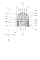
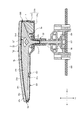
なお、以下で説明する図5は、指針の指針延在方向、及び、指針光軸方向に沿った断面図であり、図6、図7は、指針の指針光軸方向、及び、指針幅方向に沿った断面図である。また、図5、図6、図7は、一部簡略化し模式的な断面図として図示している。
FIG. 5 described below is a cross-sectional view along the pointer extending direction of the pointer and the pointer optical axis direction, and FIGS. 6 and 7 are the pointer optical axis direction of the pointer and the pointer width direction. FIG. 5, FIG. 6, and FIG. 7 are partially simplified and illustrated as schematic sectional views.
[実施形態1]
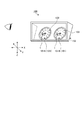
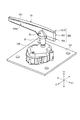
本実施形態に係る車両表示装置用指針としての指針1は、図1に示すように、車両に搭載される車両表示装置100に適用される。車両表示装置100は、いわゆる車載メータを構成するものであり、例えば、車両のダッシュボードに設けられたインストルメントパネルに搭載され、車両の運転に供される情報として当該車両に関する種々の情報を表示する。
[Embodiment 1]
As shown in FIG. 1, a pointer 1 as a vehicle display device pointer according to the present embodiment is applied to a vehicle display device 100 mounted on a vehicle. The vehicle display device 100 constitutes a so-called on-vehicle meter, and is mounted on an instrument panel provided on a dashboard of the vehicle, for example, and displays various information related to the vehicle as information used for driving the vehicle. To do.
なお、図1等に示す車両表示装置100の幅方向Xとは、典型的には、この車両表示装置100が適用される車両の車幅方向に相当する。以下の説明では、車両表示装置100の幅方向Xにおいて、当該車両表示装置100の前面に向かって左側(図1中左側)を幅方向X左側、向かって右側(図1中右側)を幅方向X右側という場合がある。また、車両表示装置100の奥行き方向Yとは、典型的には、この車両表示装置100が適用される車両の前後方向に相当する。また、車両表示装置100の前面側とは、奥行き方向Yにおいて車両の運転席と対面する側であり、典型的には、当該運転席に座った運転者によって視認される側である。一方、車両表示装置100の背面側とは、奥行き方向Yにおいて前面側とは反対側であり、典型的には、インストルメントパネルの内部に収容される側である。車両表示装置100の高さ方向Zとは、典型的には、この車両表示装置100が適用される車両の高さ方向に相当し、例えば、鉛直方向に沿った方向である。また、以下の説明で用いる各方向は、特に断りのない限り、車両表示装置100がインストルメントパネルに組み付けられた状態での方向を表す。
Note that the width direction X of the vehicle display device 100 shown in FIG. 1 and the like typically corresponds to the vehicle width direction of a vehicle to which the vehicle display device 100 is applied. In the following description, in the width direction X of the vehicle display device 100, the left side (left side in FIG. 1) toward the front of the vehicle display device 100 is the left side in the width direction X, and the right side (right side in FIG. 1) is the width direction. X may be called the right side. The depth direction Y of the vehicle display device 100 typically corresponds to the front-rear direction of the vehicle to which the vehicle display device 100 is applied. Further, the front side of the vehicle display device 100 is a side facing the driver's seat of the vehicle in the depth direction Y, and is typically a side visually recognized by a driver sitting in the driver's seat. On the other hand, the back side of the vehicle display device 100 is the side opposite to the front side in the depth direction Y, and is typically the side accommodated inside the instrument panel. The height direction Z of the vehicle display device 100 typically corresponds to the height direction of the vehicle to which the vehicle display device 100 is applied, for example, a direction along the vertical direction. In addition, each direction used in the following description represents a direction in a state where the vehicle display device 100 is assembled to the instrument panel unless otherwise specified.
具体的には、車両表示装置100は、車両に関する種々の情報を表示する表示部101と、樹脂材料等によって構成され表示部101等を収容する筐体102とを備える。表示部101は、車両表示装置100の各部を収容する筐体102内に配置されると共に各種情報の表示面が奥行き方向Y前面側に露出する。筐体102は、例えば、奥行き方向Y背面側に配置される背面カバー、背面カバーの奥行き方向Y前面側に配置されるケース本体、ケース本体の奥行き方向Y前面側に配置される見返し部材等を含んで構成され、これらによって区画される空間部内に表示部101が配置される。そして、筐体102は、見返し部材に形成される開口を介して各表示部101の表示面が奥行き方向Y前面側に露出する。ここでは、表示部101は、一例として、車両に関する情報として、車速を表示する速度計101A、走行用動力源の出力回転数を表示する回転計101B等を含んで構成される。速度計101A、回転計101Bは、それぞれ文字板103、指針1等を含んで構成され、車両に関する種々の計測値を当該指針1によってアナログ式で表示するアナログ計器である。文字板103は、車両に関する情報として、例えば、速度、出力回転数等の計測値を表し指針1によって指し示される指標部やウォーニング表示用の図柄等が描かれている。文字板103は、例えば、透明生地のポリカーボネイト製シートであり、暗色系のインクによって、上記指標部やウォーニング表示用の図柄等に対応した形状が中抜きされた印刷が施される。表示部101は、光源部から照射される光が、文字板103において指標部やウォーニング表示用の図柄等が切り抜きされた部分を透過することで当該指標部やウォーニング表示用の図柄等が表示状態となる。指針1によって指し示される指標部は、この指針1の先端の回動軌跡に沿った円弧、当該円弧に沿って等間隔で付された複数の目盛、数字等を含んで構成される。指針1は、表示部101の一部を構成し、車両に関する情報を指し示す。指針1は、文字板103の奥行き方向Y前面側に位置し、車両に関する種々の計測値(速度、出力回転数等)に応じて指標部の所定の位置を指し示す。各表示部101は、指針1によって現在の速度、出力回転数が指し示される。
Specifically, the vehicle display device 100 includes a display unit 101 that displays various information related to the vehicle, and a housing 102 that is made of a resin material or the like and houses the display unit 101 or the like. The display unit 101 is disposed in a housing 102 that accommodates each unit of the vehicle display device 100, and a display surface for various information is exposed on the front side in the depth direction Y. The housing 102 includes, for example, a back cover disposed on the back side in the depth direction Y, a case body disposed on the front side in the depth direction Y of the back cover, a turning member disposed on the front side in the depth direction Y of the case body, and the like. The display part 101 is arrange | positioned in the space part comprised including and divided by these. And the display surface of each display part 101 is exposed to the depth direction Y front side through the opening formed in the turning member. Here, as an example, the display unit 101 includes a speedometer 101A that displays the vehicle speed, a tachometer 101B that displays the output rotational speed of the driving power source, and the like as information about the vehicle. The speedometer 101 </ b> A and the tachometer 101 </ b> B are configured to include a dial plate 103, a pointer 1, and the like, and are various analog instruments that display various measurement values related to the vehicle in an analog manner using the pointer 1. On the dial 103, as information about the vehicle, for example, an indicator part indicating a measured value such as a speed and an output rotation number, and a design for a warning display indicated by the pointer 1 are drawn. The dial plate 103 is, for example, a polycarbonate sheet made of a transparent fabric, and is printed with a shape corresponding to the indicator portion, the warning display pattern, or the like with dark ink. In the display unit 101, the light emitted from the light source unit is transmitted through a portion of the dial plate 103 where the indicator unit and the warning display symbol are cut out, so that the indicator unit and the warning display symbol are displayed. It becomes. The indicator portion pointed to by the pointer 1 includes an arc along the turning trajectory of the tip of the pointer 1, and a plurality of scales, numbers, and the like attached at equal intervals along the arc. The pointer 1 constitutes a part of the display unit 101 and indicates information related to the vehicle. The pointer 1 is located on the front side of the dial 103 in the depth direction Y, and points to a predetermined position of the indicator portion according to various measurement values (speed, output rotation speed, etc.) relating to the vehicle. Each display unit 101 is indicated by the pointer 1 with the current speed and the output rotation speed.
以下、図2、図3、図4、図5、図6、図7の各図を参照して上記のような車両表示装置100に適用される指針1の各構成について詳細に説明する。なお、以下で説明する指針1において、互いに交差する第1方向、第2方向、及び、第3方向のうち、第1方向を「指針延在方向X1」とし、第2方向を「指針光軸方向Y1」とし、第3方向を「指針幅方向Z1」とする。ここでは、指針延在方向X1と指針光軸方向Y1と指針幅方向Z1とは、相互に略直交する。典型的には、指針光軸方向Y1は、奥行き方向Yに沿った方向である。以下の説明で用いる各方向は、特に断りのない限り、指針1の各部が互いに組み付けられた状態での方向を表す。また、速度計101Aの指針1と回転計101Bの指針1とは、ほぼ同様の構成であるのでここでは共通の説明とする。
Hereinafter, each configuration of the pointer 1 applied to the vehicle display device 100 as described above will be described in detail with reference to FIGS. 2, 3, 4, 5, 6, and 7. In the pointer 1 described below, of the first direction, the second direction, and the third direction intersecting with each other, the first direction is the “pointer extending direction X1” and the second direction is the “pointer optical axis”. The direction is Y1 ”, and the third direction is“ pointer width direction Z1 ”. Here, the pointer extending direction X1, the pointer optical axis direction Y1, and the pointer width direction Z1 are substantially orthogonal to each other. Typically, the pointer optical axis direction Y1 is a direction along the depth direction Y. Each direction used in the following description represents a direction in a state where the parts of the pointer 1 are assembled to each other unless otherwise specified. Further, since the pointer 1 of the speedometer 101A and the pointer 1 of the tachometer 101B have substantially the same configuration, a common description is given here.
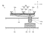
ここでまず、指針1を回転駆動させるための構成について説明する。指針1は、図5に示すように、筐体102(図1参照)内に配置される駆動部としてのモータ104によって回転駆動される。モータ104は、筐体102内に配置される配線板105の奥行き方向Y前面側の実装面に実装される。モータ104は、指針1の駆動源であり、回転駆動可能である回転軸106を有する。回転軸106は、モータ104のロータ軸を構成するものである。また、車両表示装置100は、モータ104と配線板105との間の実装面に実装される光源107を備え、回転軸106は、指針光軸方向Y1(奥行き方向Y)に対して、当該光源107と対向する位置に設けられ、指針光軸方向Y1に沿って延在する。モータ104、光源107は、配線板105の実装面に実装されて筐体102(図1参照)内に収容される。光源107は、奥行き方向Y(指針光軸方向Y1)前面側に向けて光を照射するものである。つまりここでは、光源107による光の照射方向、言い換えれば、光源107の光軸方向は、指針光軸方向Y1に沿った方向である。光源107は、例えば、LED(Light Emitting Diode)素子等によって構成されるがこれに限らない。そして、本実施形態の回転軸106は、光を透過する光透過性の樹脂材料によって形成され、奥行き方向Y(指針光軸方向Y1)に対して光源107と対向すると共にモータ104から奥行き方向Yに沿って柱状に延在するようにして奥行き方向Y前面側に突設される。回転軸106は、文字板103に形成された開口103aを介して光源107側とは反対側の端部、すなわち、奥行き方向Y前面側の端部に指針1が接続される。回転軸106は、光源107から照射された光を指針1側に導く導光軸として機能する。すなわち、回転軸106は、光源107から照射された光が当該光源107側の端部に入射し、当該入射した光を奥行き方向Y前面側の指針1側に導光し出射する。指針1は、文字板103の奥行き方向Y前面側に位置し、回転軸106に接続されモータ104が駆動することで回転駆動されると共に光源107からの光によって発光する。
First, a configuration for rotating the pointer 1 will be described. As shown in FIG. 5, the pointer 1 is rotationally driven by a motor 104 serving as a drive unit disposed in a housing 102 (see FIG. 1). The motor 104 is mounted on the mounting surface on the front side in the depth direction Y of the wiring board 105 disposed in the housing 102. The motor 104 is a driving source of the pointer 1 and has a rotating shaft 106 that can be driven to rotate. The rotating shaft 106 constitutes the rotor shaft of the motor 104. Further, the vehicle display device 100 includes a light source 107 mounted on a mounting surface between the motor 104 and the wiring board 105, and the rotation shaft 106 has the light source with respect to the pointer optical axis direction Y1 (depth direction Y). 107 is provided at a position opposed to 107, and extends along the pointer optical axis direction Y1. The motor 104 and the light source 107 are mounted on the mounting surface of the wiring board 105 and accommodated in the housing 102 (see FIG. 1). The light source 107 irradiates light toward the front side in the depth direction Y (pointer optical axis direction Y1). That is, here, the light irradiation direction of the light source 107, in other words, the optical axis direction of the light source 107 is a direction along the pointer optical axis direction Y1. The light source 107 includes, for example, an LED (Light Emitting Diode) element, but is not limited thereto. The rotating shaft 106 of the present embodiment is formed of a light-transmitting resin material that transmits light. The rotating shaft 106 is opposed to the light source 107 in the depth direction Y (pointer optical axis direction Y1) and from the motor 104 to the depth direction Y. And projecting on the front side in the depth direction Y so as to extend in a columnar shape. The rotating shaft 106 is connected to the pointer 1 at the end opposite to the light source 107 side, that is, the end on the front side in the depth direction Y, through an opening 103 a formed in the dial 103. The rotation shaft 106 functions as a light guide shaft that guides light emitted from the light source 107 to the pointer 1 side. That is, the rotating shaft 106 enters the light emitted from the light source 107 into the end on the light source 107 side, guides the incident light to the pointer 1 side on the front side in the depth direction Y, and emits it. The pointer 1 is located on the front side of the dial 103 in the depth direction Y, is connected to the rotating shaft 106 and is driven to rotate when driven by the motor 104 and emits light by light from the light source 107.
より具体的には、本実施形態の指針1は、図2、図3、図4、図5、図6、図7に示すように、接続基部としての指針ステム2と、指針発光体3と、バランサ4と、指針遮光体としての指針キャップ5とを備え、上記のように回転軸106を介して導光された光によって指針発光体3の全体が発光する。
More specifically, the pointer 1 of this embodiment includes a pointer stem 2 as a connection base, a pointer light emitter 3, and a pointer illuminator 3 as shown in FIGS. 2, 3, 4, 5, 6, and 7. The balancer 4 and the pointer cap 5 as a pointer light-shielding body are provided, and the entire pointer light-emitting body 3 emits light by the light guided through the rotating shaft 106 as described above.
具体的には、指針ステム2は、回転軸106と指針発光体3とを接続し、指針発光体3を回転軸106に一体回転可能に支持する接続支持部材である。指針ステム2は、基部21、及び、円筒軸部22を含んで構成され、これらが光を遮光する遮光性の樹脂材料によって一体に形成される。
Specifically, the pointer stem 2 is a connection support member that connects the rotary shaft 106 and the pointer light emitter 3 and supports the pointer light emitter 3 so as to be integrally rotatable with the rotary shaft 106. The pointer stem 2 includes a base portion 21 and a cylindrical shaft portion 22, and these are integrally formed of a light-blocking resin material that blocks light.
基部21は、指針延在方向X1に沿って延在する板状に形成され指針光軸方向Y1の一方側の面に指針発光体3を支持する部分である。基部21は、円筒軸部22が接続される部分が略円形板状に形成され、当該略円形板状の部分に組み付け孔部21aが形成される(図6等参照)。組み付け孔部21aは、指針キャップ5が組み付けられる部分であり、ここでは、2つ設けられる。
The base portion 21 is a portion that is formed in a plate shape extending along the pointer extending direction X1 and that supports the pointer light emitter 3 on one surface in the pointer optical axis direction Y1. The base 21 is formed in a substantially circular plate-like portion to which the cylindrical shaft portion 22 is connected, and an assembly hole portion 21a is formed in the substantially circular plate-like portion (see FIG. 6 and the like). The assembly hole 21a is a part to which the pointer cap 5 is assembled, and here, two are provided.
円筒軸部22は、回転軸106と指針発光体3とを接続するいわゆる袴とも呼ばれる部分である。円筒軸部22は、内部が中空の円筒状に形成され、基部21の略円形板状の部分から指針光軸方向Y1に沿って突出して形成される。円筒軸部22は、基部21において指針発光体3を支持する面とは反対側に突出して形成され、内部の中空状の部分が基部21を貫通し、指針光軸方向Y1の両側に開口している(図5、図6等参照)。円筒軸部22は、指針光軸方向Y1の一方の端部開口に回転軸106が嵌合され、指針光軸方向Y1の他方の端部開口に後述する指針発光体3の軸部31aが嵌合されることで、回転軸106と軸部31aとを一体回転可能に接続する。
The cylindrical shaft portion 22 is a portion called a soot that connects the rotary shaft 106 and the pointer light emitter 3. The cylindrical shaft portion 22 is formed in a hollow cylindrical shape, and is formed so as to protrude from the substantially circular plate-shaped portion of the base portion 21 along the pointer optical axis direction Y1. The cylindrical shaft portion 22 is formed so as to protrude on the side opposite to the surface that supports the pointer light emitter 3 in the base portion 21, and an internal hollow portion penetrates the base portion 21 and opens on both sides in the pointer optical axis direction Y1. (See FIG. 5, FIG. 6, etc.). The cylindrical shaft portion 22 has a rotary shaft 106 fitted into one end opening in the pointer optical axis direction Y1, and a shaft portion 31a of a pointer light emitter 3 to be described later fitted into the other end opening in the pointer optical axis direction Y1. As a result, the rotary shaft 106 and the shaft portion 31a are connected so as to be integrally rotatable.
指針発光体3は、回転軸106を介して導光された光によって発光する発光部材であり、指針本体を構成する。本実施形態の指針発光体3は、第1光透過体としての指針プリズム部材31、第2光透過体としての光透過性キャップ32、及び、拡散層33を有し、これらが組み合わせられることで構成される。
The pointer light emitter 3 is a light emitting member that emits light by light guided through the rotation shaft 106, and constitutes a pointer main body. The pointer light emitter 3 of the present embodiment includes a pointer prism member 31 as a first light transmitter, a light transmissive cap 32 as a second light transmitter, and a diffusion layer 33, and these are combined. Composed.
指針プリズム部材31は、光透過性材料によって指針延在方向X1に沿って延在して形成され、軸部31aに入射した光を第1出射面31eから指針光軸方向Y1に沿って前面側に出射するものである。指針プリズム部材31は、軸部31a、本体部31b、被支持部31c、導光中空部31d、及び、第1出射面31eを含んで構成され、これらが光を透過する光透過性の樹脂材料によって一体に形成される。
The pointer prism member 31 is formed of a light transmissive material so as to extend along the pointer extending direction X1, and the light incident on the shaft portion 31a is front-side along the pointer optical axis direction Y1 from the first emission surface 31e. Is emitted. The pointer prism member 31 includes a shaft portion 31a, a main body portion 31b, a supported portion 31c, a light guide hollow portion 31d, and a first emission surface 31e, and these are light transmissive resin materials that transmit light. Are integrally formed.
軸部31aは、指針光軸方向Y1に沿って柱状に形成される部分であり、上述したように、指針ステム2の円筒軸部22を介して回転軸106と一体回転可能に接続される(図5、図6等参照)。軸部31aは、当該回転軸106を介して導光された光が指針光軸方向Y1に沿って入射する入射部として機能する。
The shaft portion 31a is a portion formed in a columnar shape along the pointer optical axis direction Y1, and as described above, is connected to the rotary shaft 106 so as to be integrally rotatable via the cylindrical shaft portion 22 of the pointer stem 2 ( (See FIGS. 5 and 6). The shaft portion 31a functions as an incident portion on which light guided through the rotation shaft 106 enters along the pointer optical axis direction Y1.
本体部31bは、軸部31aの端部から指針延在方向X1に沿って延在して形成される部分である。本体部31bは、軸部31aにおいて回転軸106と接続される側の端部と反対側の端部に設けられる。本体部31bは、軸部31aの端部から指針延在方向X1の両側に突出するように形成される。本体部31bは、指針プリズム部材31が指針ステム2に組み付けられ支持された状態で、一方側(後述のバランサ4が配置される側とは反対側)の突出量が他方側(後述のバランサ4が配置される側)の突出量より多くなるように、軸部31aの端部からの突出量が設定されている(図3、図5等参照)。本体部31bは、指針光軸方向Y1に対して軸部31a側とは反対側の面、すなわち、奥行き方向Y前面側の面が第1出射面31eを構成する。
The main body portion 31b is a portion formed extending from the end portion of the shaft portion 31a along the pointer extending direction X1. The main body 31b is provided at the end of the shaft 31a opposite to the end connected to the rotating shaft 106. The main body portion 31b is formed so as to protrude from the end portion of the shaft portion 31a to both sides in the pointer extending direction X1. The main body 31b has a protrusion amount on one side (the side opposite to a side where a later-described balancer 4 is disposed) in the state where the pointer prism member 31 is assembled and supported on the pointer stem 2, and the other side (the later-described balancer 4 described later). The amount of protrusion from the end of the shaft portion 31a is set so as to be larger than the amount of protrusion on the side where the is disposed) (see FIGS. 3 and 5). In the main body 31b, a surface opposite to the shaft 31a side with respect to the pointer optical axis direction Y1, that is, a surface on the front side in the depth direction Y forms a first emission surface 31e.
被支持部31cは、指針ステム2の基部21上に支持される部分であり、本体部31bから指針幅方向Z1の両側に板状に突出して形成される(図3、図6等参照)。各被支持部31cは、軸部31aと本体部31bとの接続部分に設けられる。各被支持部31cは、それぞれ組み付け孔部31fが形成される(図6等参照)。組み付け孔部31fは、指針キャップ5が組み付けられる部分であり、ここでは、各被支持部31cに1つずつ、合計2つ設けられる。
The supported portion 31c is a portion that is supported on the base portion 21 of the pointer stem 2, and is formed to project from the main body portion 31b on both sides in the pointer width direction Z1 (see FIGS. 3 and 6). Each supported portion 31c is provided at a connection portion between the shaft portion 31a and the main body portion 31b. Each supported portion 31c has an assembly hole portion 31f (see FIG. 6 and the like). The assembly hole portion 31f is a portion to which the pointer cap 5 is assembled, and here, a total of two are provided, one for each supported portion 31c.
導光中空部31dは、軸部31aと本体部31bとの接続部分、ここでは、当該接続部分の本体部31b側に中空状に形成される部分である(図3、図5、図6等参照)。導光中空部31dは、指針幅方向Z1の両側に開口を有する中空状に形成される。導光中空部31dは、指針延在方向X1、及び、指針光軸方向Y1に沿った断面視(図5参照)にて(言い換えれば、指針幅方向Z1に視て)、略四分円形状、あるいは、略扇形状に形成される。さらに言えば、導光中空部31dは、当該断面視にて、指針光軸方向Y1の軸部31a側が先細りの形状であり、指針光軸方向Y1に沿って軸部31aから離間するにしたがって指針延在方向X1に沿った幅が徐々に広くなるような形状に形成される。導光中空部31dは、当該導光中空部31dを形成する面が軸部31aに入射した光を指針延在方向X1に反射し拡散させて本体部31bの全体に導光する反射導光面として機能する。
The light guide hollow portion 31d is a connection portion between the shaft portion 31a and the main body portion 31b, here, a portion formed in a hollow shape on the main body portion 31b side of the connection portion (FIGS. 3, 5, 6, etc.) reference). The light guide hollow portion 31d is formed in a hollow shape having openings on both sides in the pointer width direction Z1. The light guide hollow portion 31d has a substantially quadrant shape in a cross-sectional view (see FIG. 5) along the pointer extending direction X1 and the pointer optical axis direction Y1 (in other words, as viewed in the pointer width direction Z1). Alternatively, it is formed in a substantially fan shape. More specifically, the light guide hollow portion 31d has a tapered shape on the side of the shaft portion 31a in the pointer optical axis direction Y1 in the cross-sectional view, and the pointer becomes closer to the shaft portion 31a along the pointer optical axis direction Y1. It is formed in a shape such that the width along the extending direction X1 gradually increases. The light guide hollow portion 31d is a reflective light guide surface in which the surface forming the light guide hollow portion 31d reflects and diffuses the light incident on the shaft portion 31a in the pointer extending direction X1 and guides it to the entire body portion 31b. Function as.
第1出射面31eは、指針プリズム部材31において、回転軸106から軸部31aに入射し、導光中空部31dによって指針延在方向X1に反射、拡散され本体部31bに導光された光を指針光軸方向Y1に沿って奥行き方向Y前面側に出射する面である。第1出射面31eは、上述したように、本体部31bにおいて、指針光軸方向Y1に対して軸部31a側とは反対側の面、ここでは、奥行き方向Y前面側の面によって構成される。第1出射面31eは、本体部31bの形状に合わせて指針延在方向X1に沿って延在する。本実施形態の第1出射面31eは、平坦面として形成される。
The first light exit surface 31e receives light that is incident on the shaft portion 31a from the rotating shaft 106 and reflected and diffused in the pointer extending direction X1 by the light guide hollow portion 31d and guided to the main body portion 31b in the pointer prism member 31. This is a surface that exits in the depth direction Y front side along the pointer optical axis direction Y1. As described above, the first emission surface 31e is constituted by a surface of the main body 31b opposite to the shaft 31a side with respect to the pointer optical axis direction Y1, here, a surface on the front side in the depth direction Y. . The first emission surface 31e extends along the pointer extending direction X1 in accordance with the shape of the main body 31b. The first emission surface 31e of the present embodiment is formed as a flat surface.
光透過性キャップ32は、光透過性材料によって指針延在方向X1に沿って延在しかつ指針光軸方向Y1に対して第1出射面31eと対向して形成され、第1出射面31eから出射され入射面32bに入射した光を第2出射面32cから指針光軸方向Y1に沿って前面側に出射するものである。光透過性キャップ32は、本体部32a、入射面32b、及び、第2出射面32cを含んで構成され、これらが光を透過する光透過性の樹脂材料によって一体に形成される。
The light transmissive cap 32 is formed of a light transmissive material so as to extend along the pointer extending direction X1 and to face the first emission surface 31e with respect to the pointer optical axis direction Y1, and from the first emission surface 31e. Light emitted and incident on the incident surface 32b is emitted from the second emission surface 32c to the front side along the pointer optical axis direction Y1. The light transmissive cap 32 includes a main body portion 32a, an incident surface 32b, and a second emission surface 32c, and these are integrally formed of a light transmissive resin material that transmits light.
本体部32aは、指針プリズム部材31の本体部31bの形状に合わせて指針延在方向X1に沿って直線棒状に延在して形成される。本体部32aは、指針光軸方向Y1に対して指針プリズム部材31の第1出射面31eと対向する面、すなわち、奥行き方向Y背面側の面が入射面32bを構成する。一方、本体部32aは、指針光軸方向Y1に対して指針プリズム部材31の第1出射面31eと対向する面とは反対側の面、すなわち、奥行き方向Y前面側の面が第2出射面32cを構成し、当該第2出射面32cが奥行き方向Y前面側の意匠面として機能する。
The main body portion 32a is formed to extend in a straight bar shape along the pointer extending direction X1 in accordance with the shape of the main body portion 31b of the pointer prism member 31. In the main body 32a, a surface facing the first exit surface 31e of the pointer prism member 31 with respect to the pointer optical axis direction Y1, that is, a surface on the back side in the depth direction Y forms an incident surface 32b. On the other hand, in the main body 32a, the surface opposite to the surface facing the first emission surface 31e of the pointer prism member 31 with respect to the pointer optical axis direction Y1, that is, the surface on the front side in the depth direction Y is the second emission surface. 32c, and the second emission surface 32c functions as a design surface on the front side in the depth direction Y.
入射面32bは、光透過性キャップ32において、指針プリズム部材31の第1出射面31eから出射された光が入射する面である。ここでは、入射面32bは、指針プリズム部材31の第1出射面31eから出射され後述の拡散層33によって拡散された光が入射する。入射面32bは、上述したように、本体部32aにおいて、指針光軸方向Y1に対して第1出射面31eと対向する面、ここでは、奥行き方向Y背面側の面によって構成される。入射面32bは、本体部32aの形状に合わせて指針延在方向X1に沿って延在する。本実施形態の入射面32bは、平坦面として形成される。
The incident surface 32 b is a surface on the light transmissive cap 32 on which light emitted from the first emission surface 31 e of the pointer prism member 31 is incident. Here, the light incident from the first exit surface 31e of the pointer prism member 31 and diffused by the later-described diffusion layer 33 enters the entrance surface 32b. As described above, the incident surface 32b is configured by a surface facing the first emission surface 31e with respect to the pointer optical axis direction Y1 in the main body portion 32a, here, a surface on the back side in the depth direction Y. The incident surface 32b extends along the pointer extending direction X1 in accordance with the shape of the main body portion 32a. In this embodiment, the incident surface 32b is formed as a flat surface.
第2出射面32cは、光透過性キャップ32において、入射面32bに入射した光を指針光軸方向Y1に沿って奥行き方向Y前面側に出射する面である。第2出射面32cは、上述したように、本体部32aにおいて、指針光軸方向Y1に対して指針プリズム部材31の第1出射面31eと対向する面とは反対側の面、ここでは、奥行き方向Y前面側の面によって構成される。第2出射面32cは、本体部32aの形状に合わせて指針延在方向X1に沿って延在する。
The second emission surface 32c is a surface that emits light incident on the incident surface 32b to the front side in the depth direction Y along the pointer optical axis direction Y1 in the light-transmitting cap 32. As described above, the second emission surface 32c is a surface of the main body 32a opposite to the surface facing the first emission surface 31e of the pointer prism member 31 with respect to the pointer optical axis direction Y1, in this case, the depth. It is comprised by the surface of the direction Y front side. The second emission surface 32c extends along the pointer extending direction X1 in accordance with the shape of the main body portion 32a.
また、本実施形態の光透過性キャップ32は、本体部32aの入射面32b側の縁部に突出縁部32dを有する(図7参照)。突出縁部32dは、本体部32aの入射面32b側の各縁部から指針光軸方向Y1に沿って指針プリズム部材31側に突出して形成される。そして、本実施形態の光透過性キャップ32は、当該突出縁部32dが後述する指針キャップ5の側壁部5dの端面に密着しマウントされるようにして設けられる。光透過性キャップ32は、例えば、二色成形により後述する指針キャップ5と一体で形成される。ここでは、光透過性キャップ32は、指針光軸方向Y1に対して入射面32bが第1出射面31eとの間に隙間32eを有して位置するように、突出縁部32dが後述する指針キャップ5の側壁部5dの端面に密着して設けられる(図7参照)。
In addition, the light transmissive cap 32 of the present embodiment has a protruding edge 32d at the edge on the incident surface 32b side of the main body 32a (see FIG. 7). The protruding edge portion 32d is formed to protrude from the respective edge portions on the incident surface 32b side of the main body portion 32a toward the pointer prism member 31 side along the pointer optical axis direction Y1. The light transmitting cap 32 of the present embodiment is provided such that the protruding edge portion 32d is mounted in close contact with the end surface of the side wall portion 5d of the pointer cap 5 described later. The light transmissive cap 32 is formed integrally with a pointer cap 5 described later by, for example, two-color molding. Here, the light-transmitting cap 32 has a protrusion edge 32d, which will be described later, such that the incident surface 32b is positioned with a gap 32e between the first light exit surface 31e and the pointer optical axis direction Y1. It is provided in close contact with the end surface of the side wall 5d of the cap 5 (see FIG. 7).
そして、光透過性キャップ32は、第2出射面32cが光を屈折させて発散させるレンズを構成するように湾曲して曲面状に形成される(図7参照)。ここでは、第2出射面32cは、指針光軸方向Y1、及び、指針幅方向Z1に沿った断面視(図7参照)にて(言い換えれば、指針延在方向X1に視て)、指針光軸方向Y1に対して入射面32bとは反対側、すなわち、出射側に突出した凸部状の略半円弧状に形成される。
The light transmissive cap 32 is curved and formed in a curved surface so that the second emission surface 32c forms a lens that refracts and diverges light (see FIG. 7). Here, the second emission surface 32c is shown in cross-sectional view (see FIG. 7) along the pointer optical axis direction Y1 and the pointer width direction Z1 (in other words, as viewed in the pointer extending direction X1). It is formed in a substantially semicircular arc shape of a convex portion protruding to the opposite side to the incident surface 32b with respect to the axial direction Y1, that is, the emission side.
拡散層33は、光を拡散させる層である。本実施形態の拡散層33は、指針プリズム部材31の第1出射面31eに密着して設けられ、指針プリズム部材31の第1出射面31eから出射され光透過性キャップ32の入射面32bに入射する光を拡散させる。より詳細には、拡散層33は、第1出射面31eの入射面32b側の面、さらに言えば、隙間32e側の面に密着して設けられる。拡散層33は、例えば、ホットスタンプ印刷、塗料の複数回の塗布、フィルム転写法等によって透光性着色層として構成され当該透光性着色層に着色された色によって指針発光体3の発光色(表示色)を自由に設定することができる。ここでは、拡散層33は、白色の透光性着色層として構成される。
The diffusion layer 33 is a layer that diffuses light. The diffusion layer 33 of the present embodiment is provided in close contact with the first emission surface 31 e of the pointer prism member 31, is emitted from the first emission surface 31 e of the pointer prism member 31, and is incident on the incident surface 32 b of the light transmissive cap 32. Diffuse light. More specifically, the diffusion layer 33 is provided in close contact with the surface on the incident surface 32b side of the first emission surface 31e, more specifically, the surface on the gap 32e side. The diffusing layer 33 is configured as a light-transmitting colored layer by, for example, hot stamp printing, coating a plurality of times, a film transfer method, or the like, and the light emission color of the pointer light emitter 3 by the color colored in the light-transmitting colored layer. (Display color) can be set freely. Here, the diffusion layer 33 is configured as a white translucent colored layer.
バランサ4は、指針ステム2に支持される指針発光体3との重量バランスを調整する部分である。バランサ4は、指針ステム2の基部21において指針発光体3を支持する面の指針延在方向X1の一方の端部に設けられる(図3、図5等参照)。バランサ4は、指針発光体3を構成する指針プリズム部材31と指針ステム2との間に介在する。より詳細には、指針プリズム部材31の本体部31bの突出量が少ない側の端部と指針ステム2の基部21との間に介在する。
The balancer 4 is a part that adjusts the weight balance with the pointer light emitter 3 supported by the pointer stem 2. The balancer 4 is provided at one end portion in the pointer extending direction X1 of the surface that supports the pointer light emitter 3 in the base portion 21 of the pointer stem 2 (see FIGS. 3 and 5). The balancer 4 is interposed between the pointer prism member 31 constituting the pointer light emitter 3 and the pointer stem 2. More specifically, the pointer prism member 31 is interposed between the end portion of the main body portion 31b on the side where the protruding amount is small and the base portion 21 of the pointer stem 2.
指針キャップ5は、指針発光体3に装着され一部の光を遮光する遮光部材である。指針キャップ5は、遮光性材料によって指針延在方向X1に沿って延在して形成され、指針プリズム部材31を指針幅方向Z1の両側から覆い指針プリズム部材31から指針幅方向Z1に沿って漏れる光を遮光する。指針キャップ5は、軸部カバー部5a、及び、スリット部5bを含んで構成され、これらが光を遮光する遮光性の樹脂材料によって一体に形成される。
The pointer cap 5 is a light blocking member that is attached to the pointer light emitter 3 and blocks a part of light. The pointer cap 5 is formed to extend along the pointer extending direction X1 with a light shielding material, covers the pointer prism member 31 from both sides of the pointer width direction Z1, and leaks from the pointer prism member 31 along the pointer width direction Z1. Block out light. The pointer cap 5 includes a shaft portion cover portion 5a and a slit portion 5b, and these are integrally formed of a light-blocking resin material that blocks light.
軸部カバー部5aは、ドーム状に形成され、指針プリズム部材31の第1出射面31e側から装着され、ここでは当該指針プリズム部材31の軸部31a、被支持部31c等を含む部分を覆う。また、軸部カバー部5aは、ドーム状の内部に柱状の装着軸部5cが形成される(図6参照)。ここでは、装着軸部5cは、2つ設けられる。
The shaft portion cover portion 5a is formed in a dome shape and is mounted from the first emission surface 31e side of the pointer prism member 31, and here covers a portion including the shaft portion 31a, the supported portion 31c, etc. of the pointer prism member 31. . Further, the shaft cover portion 5a has a columnar mounting shaft portion 5c formed inside a dome (see FIG. 6). Here, two mounting shaft portions 5c are provided.
スリット部5bは、側壁部5dを有し、当該側壁部5dによって指針プリズム部材31の本体部31bを収容する中空状部5eが形成された部分である。側壁部5dは、軸部カバー部5aから指針光軸方向Y1の前面側に突出して延在しかつ指針延在方向X1に沿って延在して枠状に形成され、上記中空状部5eを区画する。言い換えれば、側壁部5dは、中空状部5eを囲うようにして指針光軸方向Y1に沿って立設される壁体である。中空状部5eは、軸部カバー部5aの内部と連通するようにして形成され、指針光軸方向Y1の前面側に開口する。スリット部5bは、軸部カバー部5aが指針プリズム部材31に装着された状態で、上記中空状部5e内に指針プリズム部材31における本体部31bが収容され、上記開口から当該本体部31bの第1出射面31e、及び、拡散層33を指針光軸方向Y1前面側に露出させる。スリット部5bは、中空状部5e内に本体部31bが収容された状態で、側壁部5dが少なくとも指針プリズム部材31の本体部31bを指針幅方向Z1の両側から挟み込んで覆い、指針プリズム部材31の本体部31bから指針幅方向Z1に沿って漏れる光、言い換えれば、第1出射面31e以外から出射される光を遮光する。
The slit part 5b has a side wall part 5d, and is a part in which a hollow part 5e for accommodating the main body part 31b of the pointer prism member 31 is formed by the side wall part 5d. The side wall portion 5d extends from the shaft portion cover portion 5a to the front side in the pointer optical axis direction Y1 and extends along the pointer extending direction X1, and is formed in a frame shape. Partition. In other words, the side wall portion 5d is a wall body that is erected along the pointer optical axis direction Y1 so as to surround the hollow portion 5e. The hollow portion 5e is formed so as to communicate with the inside of the shaft portion cover portion 5a and opens to the front side in the pointer optical axis direction Y1. The slit portion 5b is configured such that the main body portion 31b of the pointer prism member 31 is accommodated in the hollow portion 5e in a state in which the shaft portion cover portion 5a is attached to the pointer prism member 31, and the main body portion 31b is disposed through the opening. The one exit surface 31e and the diffusion layer 33 are exposed to the front side of the pointer optical axis direction Y1. In the state where the main body portion 31b is accommodated in the hollow portion 5e, the slit portion 5b covers at least the main body portion 31b of the pointer prism member 31 from both sides in the pointer width direction Z1. The light leaking from the main body portion 31b along the pointer width direction Z1, in other words, the light emitted from other than the first emission surface 31e is shielded.
ここで、指針キャップ5と光透過性キャップ32とは、上述したように二色成形等により一体で形成され、側壁部5dにおける第1出射面31eによる光の出射側の端面、すなわち、側壁部5dにおける指針光軸方向Y1の前面側の端面に光透過性キャップ32の突出縁部32dが密着しマウントされるようにして設けられる。これにより、光透過性キャップ32は、側壁部5dにおける第1出射面31eによる光の出射側の端面、すなわち、側壁部5dにおける指針光軸方向Y1の前面側の端面を覆う位置関係で設けられる。
Here, the pointer cap 5 and the light transmissive cap 32 are integrally formed by two-color molding or the like as described above, and the end surface on the light emission side by the first emission surface 31e in the side wall portion 5d, that is, the side wall portion. The protruding edge portion 32d of the light-transmitting cap 32 is provided in close contact with and mounted on the end surface on the front surface side in the pointer optical axis direction Y1 at 5d. Thus, the light transmissive cap 32 is provided in a positional relationship so as to cover the end surface on the light emission side by the first emission surface 31e in the side wall portion 5d, that is, the end surface on the front surface side in the pointer optical axis direction Y1 in the side wall portion 5d. .
上記のように構成される指針1は、光透過性キャップ32が一体成形された指針キャップ5における装着軸部5cが被支持部31cの組み付け孔部31fを本体部31b側から貫通すると共に当該本体部31bが側壁部5dの間に嵌り第1出射面31e、拡散層33がスリット部5bの中空状部5eの開口から露出するような位置関係で、指針キャップ5が指針プリズム部材31に装着される。指針1は、指針キャップ5が指針プリズム部材31に装着された状態で、指針プリズム部材31と指針ステム2の基部21との間にバランサ4を介在させると共に軸部カバー部5aの装着軸部5cが指針ステム2の基部21の組み付け孔部21aに組み付けられることで、指針ステム2と指針プリズム部材31とバランサ4と指針キャップ5とが一体化される。指針1は、指針ステム2と指針プリズム部材31とバランサ4と指針キャップ5とが一体化された状態で、指針プリズム部材31が指針ステム2の基部21上に支持され、指針プリズム部材31の軸部31aが指針ステム2の円筒軸部22に嵌合し回転軸106と一体回転可能に接続される。
In the pointer 1 configured as described above, the mounting shaft portion 5c of the pointer cap 5 integrally formed with the light transmitting cap 32 penetrates the assembly hole portion 31f of the supported portion 31c from the main body portion 31b side, and the main body. The pointer cap 5 is attached to the pointer prism member 31 in such a positional relationship that the portion 31b fits between the side walls 5d and the first emission surface 31e and the diffusion layer 33 are exposed from the opening of the hollow portion 5e of the slit portion 5b. The In the state in which the pointer cap 5 is mounted on the pointer prism member 31, the pointer 1 has the balancer 4 interposed between the pointer prism member 31 and the base portion 21 of the pointer stem 2 and the mounting shaft portion 5c of the shaft portion cover portion 5a. Is assembled into the assembly hole 21a of the base 21 of the pointer stem 2, so that the pointer stem 2, the pointer prism member 31, the balancer 4, and the pointer cap 5 are integrated. In the state in which the pointer stem 2, the pointer prism member 31, the balancer 4, and the pointer cap 5 are integrated, the pointer 1 is supported on the base 21 of the pointer stem 2 and the shaft of the pointer prism member 31 is The portion 31a is fitted to the cylindrical shaft portion 22 of the pointer stem 2 and is connected to the rotary shaft 106 so as to be integrally rotatable.
そして、指針1は、光源107から回転軸106を介して指針プリズム部材31の軸部31aに入射した光が導光中空部31dによって指針延在方向X1に反射、拡散され指針延在方向X1に沿って本体部31bの全体に導光され第1出射面31eから指針光軸方向Y1に沿って奥行き方向Y前面側に出射される。指針1は、第1出射面31eから出射された光が拡散層33によって拡散され、当該拡散層33によって拡散された光が隙間32eを通過して光透過性キャップ32の入射面32bに入射する。そして、指針1は、光透過性キャップ32の入射面32bに入射した光が第2出射面32cから指針光軸方向Y1に沿って奥行き方向Y前面側に出射され、この結果、指針発光体3の全体が発光する。
In the pointer 1, the light incident on the shaft portion 31 a of the pointer prism member 31 from the light source 107 via the rotation shaft 106 is reflected and diffused in the pointer extending direction X 1 by the light guide hollow portion 31 d and is diffused in the pointer extending direction X 1. Then, the light is guided to the whole main body 31b and emitted from the first emission surface 31e to the front side in the depth direction Y along the pointer optical axis direction Y1. In the pointer 1, the light emitted from the first emission surface 31e is diffused by the diffusion layer 33, and the light diffused by the diffusion layer 33 passes through the gap 32e and enters the incident surface 32b of the light transmissive cap 32. . In the pointer 1, light incident on the incident surface 32b of the light-transmitting cap 32 is emitted from the second emission surface 32c to the front side in the depth direction Y along the pointer optical axis direction Y1, and as a result, the pointer light emitter 3 The whole of emits light.
このとき、光透過性キャップ32は、図7に示すように、少なくとも指針幅方向Z1に対して、第2出射面32cによる光の出射領域T12を第1出射面31eによる光の出射領域T11より広げて当該第2出射面32cから光を出射する(図7参照)。本実施形態の光透過性キャップ32は、光の屈折効果により第2出射面32cによる光の出射領域を広げる。ここでは、光透過性キャップ32は、上述したように、入射面32bが拡散層33との間に空気層を構成する隙間32eを有して位置し、第2出射面32cが湾曲して形成されることで入射面32b、第2出射面32cが屈折面を構成する。これにより、光透過性キャップ32は、光を屈折させて発散させるレンズを構成し、当該レンズの光の屈折効果により第2出射面32cによる光の出射領域T12を第1出射面31eによる光の出射領域T11より広げる。
At this time, as shown in FIG. 7, the light-transmitting cap 32 makes the light emission region T12 by the second emission surface 32c more than the light emission region T11 by the first emission surface 31e in at least the pointer width direction Z1. The light is spread and emitted from the second emission surface 32c (see FIG. 7). The light transmissive cap 32 of the present embodiment widens the light emission region by the second emission surface 32c by the light refraction effect. Here, as described above, the light-transmitting cap 32 is formed such that the incident surface 32b has a gap 32e forming an air layer between the diffusion layer 33 and the second emission surface 32c is curved. As a result, the entrance surface 32b and the second exit surface 32c constitute a refracting surface. As a result, the light transmissive cap 32 constitutes a lens that refracts and diverges light, and the light exit region T12 by the second exit surface 32c is changed to the light exit by the first exit surface 31e due to the light refraction effect of the lens. It is wider than the emission region T11.
一方、指針1は、指針キャップ5の軸部カバー部5aが指針ステム2の基部21との間に指針プリズム部材31の被支持部31cを挟み込むようにして覆うことで回転軸106を介して導光された光のうちの漏れ光が遮光される。また、指針1は、指針キャップ5の側壁部5dが指針プリズム部材31の本体部31bを指針幅方向Z1の両側から挟み込んで覆うことで本体部31bから指針幅方向Z1に沿って漏れる光が遮光される。
On the other hand, the pointer 1 is guided through the rotating shaft 106 by covering the shaft cover portion 5a of the pointer cap 5 with the supported portion 31c of the pointer prism member 31 sandwiched between the shaft cover portion 5a and the base portion 21 of the pointer stem 2. Leaked light of the emitted light is blocked. In addition, the pointer 1 covers the main body 31b of the pointer prism member 31 from both sides of the pointer width direction Z1 by the side wall portion 5d of the pointer cap 5 so as to block light leaking from the main body 31b along the pointer width direction Z1. Is done.
以上で説明した指針1によれば、光透過性材料によって指針延在方向X1に沿って延在して形成され、入射した光を第1出射面31eから指針延在方向X1と交差する指針光軸方向Y1に沿って出射する指針プリズム部材31、光透過性材料によって指針延在方向X1に沿って延在しかつ指針光軸方向Y1に対して第1出射面31eと対向して形成され、第1出射面31eから出射され入射した光を第2出射面32cから指針光軸方向Y1に沿って出射する光透過性キャップ32、及び、第1出射面31eから出射され光透過性キャップ32に入射する光を拡散させる拡散層33を有する指針発光体3と、遮光性材料によって指針延在方向X1に沿って延在して形成され、指針プリズム部材31を指針光軸方向Y1及び指針延在方向X1と交差する指針幅方向Z1の両側から覆い指針プリズム部材31から指針幅方向Z1に沿って漏れる光を遮光する指針キャップ5とを備え、光透過性キャップ32は、少なくとも指針幅方向Z1に対して、第2出射面32cによる光の出射領域T12を第1出射面31eによる光の出射領域T11より広げて当該第2出射面32cから光を出射する。以上で説明した車両表示装置100によれば、光を照射する光源107と、回転駆動可能な回転軸106を有するモータ104と、光源107、及び、モータ104を収容する筐体102と、回転軸106に接続され回転駆動される上記指針1とを備える。
According to the pointer 1 described above, the pointer light is formed of the light transmitting material so as to extend along the pointer extending direction X1, and the incident light crosses the pointer extending direction X1 from the first emission surface 31e. A pointer prism member 31 that emits along the axial direction Y1, and is formed by the light transmissive material so as to extend along the pointer extending direction X1 and to face the first emitting surface 31e with respect to the pointer optical axis direction Y1, A light transmitting cap 32 that emits incident light emitted from the first emitting surface 31e along the pointer optical axis direction Y1 from the second emitting surface 32c, and a light transmitting cap 32 that is emitted from the first emitting surface 31e. The pointer luminous body 3 having the diffusion layer 33 for diffusing the incident light and the light-shielding material are formed to extend along the pointer extending direction X1, and the pointer prism member 31 is extended in the pointer optical axis direction Y1 and the pointer extending. Cross with direction X1 And a pointer cap 5 that covers light from both sides of the pointer width direction Z1 and shields light leaking from the pointer prism member 31 along the pointer width direction Z1. The light emission region T12 by the second emission surface 32c is expanded from the light emission region T11 by the first emission surface 31e, and light is emitted from the second emission surface 32c. According to the vehicle display device 100 described above, the light source 107 for irradiating light, the motor 104 having the rotational shaft 106 that can be driven to rotate, the light source 107, the housing 102 that houses the motor 104, and the rotational shaft. The pointer 1 is connected to 106 and driven to rotate.
したがって、指針1、車両表示装置100は、指針発光体3において、指針プリズム部材31に入射した光が第1出射面31eから指針光軸方向Y1に沿って出射され、光透過性キャップ32に入射し第2出射面32cから指針光軸方向Y1に沿って出射されることで指針発光体3の全体が発光する。このとき、指針1、車両表示装置100は、指針キャップ5の側壁部5d等によって指針プリズム部材31から指針幅方向Z1に沿って漏れる光が遮光されることで指針光軸方向Y1前面側、すなわち、運転者等によって視認される側への発光領域以外の発光領域を限定し指針発光体3の輪郭をシャープに見せることができる。また、指針1、車両表示装置100は、光源107からの光を効率的に運転者等によって視認される側へ出射することができ、ロスを抑制することができ、輝度の低下を抑制することができる。その上で、指針1、車両表示装置100は、拡散層33による光の拡散、及び、光透過性キャップ32の第2出射面32cによる出射領域T12の拡大によって指針発光体3における発光領域を広げることができる。この結果、指針1、車両表示装置100は、例えば、指針1からの漏れ光の文字板103への映り込み等を抑制しつつ、適正に指針1の発光領域を広げることができ、視認性を向上することができる。
Therefore, in the pointer 1 and the vehicle display device 100, in the pointer light emitter 3, the light incident on the pointer prism member 31 is emitted from the first emission surface 31 e along the pointer optical axis direction Y1 and is incident on the light transmitting cap 32. The entire pointer light emitter 3 emits light by being emitted from the second emission surface 32c along the pointer optical axis direction Y1. At this time, in the pointer 1 and the vehicle display device 100, the light leaking from the pointer prism member 31 along the pointer width direction Z1 is blocked by the side wall portion 5d of the pointer cap 5, etc. By limiting the light emitting area other than the light emitting area to the side visually recognized by the driver or the like, the outline of the pointer light emitter 3 can be shown sharply. In addition, the pointer 1 and the vehicle display device 100 can efficiently emit light from the light source 107 to a side visually recognized by a driver or the like, can suppress loss, and suppress a decrease in luminance. Can do. In addition, the pointer 1 and the vehicle display device 100 widen the light emitting region in the pointer light emitter 3 by diffusing light by the diffusion layer 33 and expanding the emission region T12 by the second emission surface 32c of the light transmissive cap 32. be able to. As a result, the pointer 1 and the vehicle display device 100 can appropriately widen the light emission area of the pointer 1 while suppressing, for example, reflection of leaked light from the pointer 1 onto the dial plate 103 and the like. Can be improved.
さらに、以上で説明した指針1、車両表示装置100によれば、指針キャップ5は、指針プリズム部材31を指針幅方向Z1の両側から覆い指針光軸方向Y1に沿って延在する側壁部5dを有し、光透過性キャップ32は、側壁部5dにおける第1出射面31eによる光の出射側の端面を覆う。したがって、指針1、車両表示装置100は、指針キャップ5の側壁部5dを覆うように光透過性キャップ32が設けられ、第2出射面32cによる光の出射領域T12を、当該側壁部5dを超えて広げることができるので、より適正に指針発光体3の全体を発光させることができ、例えば、光透過性キャップ32の第2出射面32cが構成する光学系の曲率(レンズ傾斜面角度)等の調整によっては指針キャップ5の側壁部5dの端面を目立たなくし視認し難くすることができる。
Furthermore, according to the pointer 1 and the vehicle display device 100 described above, the pointer cap 5 covers the pointer prism member 31 from both sides of the pointer width direction Z1, and includes the side wall portion 5d extending along the pointer optical axis direction Y1. The light-transmitting cap 32 covers the end surface on the light emission side by the first emission surface 31e in the side wall portion 5d. Therefore, the pointer 1 and the vehicle display device 100 are provided with the light transmissive cap 32 so as to cover the side wall portion 5d of the pointer cap 5, and the light emission region T12 by the second emission surface 32c exceeds the side wall portion 5d. Therefore, the entire pointer light emitter 3 can emit light more appropriately. For example, the curvature of the optical system (lens inclined surface angle) formed by the second emission surface 32c of the light transmitting cap 32, etc. Depending on the adjustment, the end face of the side wall 5d of the pointer cap 5 can be made inconspicuous and difficult to see.
さらに、以上で説明した指針1、車両表示装置100によれば、光透過性キャップ32は、光の屈折効果により第2出射面32cによる光の出射領域T12を広げる。したがって、指針1、車両表示装置100は、光透過性キャップ32が構成する光学系によって当該光透過性キャップ32に入射し第2出射面32cから出射される光を屈折させて発散させることで第2出射面32cによる光の出射領域T12を第1出射面31eによる光の出射領域T11より広げることができる。
Furthermore, according to the pointer 1 and the vehicle display device 100 described above, the light transmissive cap 32 widens the light emission region T12 by the second light emission surface 32c by the light refraction effect. Therefore, the pointer 1 and the vehicle display device 100 are configured to refract and diverge the light incident on the light transmissive cap 32 and emitted from the second light exit surface 32c by the optical system formed by the light transmissive cap 32. The light emission region T12 by the two emission surfaces 32c can be wider than the light emission region T11 by the first emission surface 31e.
さらに、以上で説明した指針1、車両表示装置100によれば、拡散層33は、第1出射面31eに密着して設けられ、光透過性キャップ32は、第1出射面31eから拡散層33を介して出射された光が入射する入射面32bが拡散層33との間に隙間32eを有して位置し、第2出射面32cが湾曲して形成される。したがって、指針1、車両表示装置100は、光透過性キャップ32の入射面32b、第2出射面32cが屈折面を構成し当該光透過性キャップ32が光を屈折させて発散させるレンズとして構成されるので、当該レンズの光の屈折効果により第2出射面32cによる光の出射領域T12を第1出射面31eによる光の出射領域T11より広げることができる。
Furthermore, according to the pointer 1 and the vehicle display device 100 described above, the diffusion layer 33 is provided in close contact with the first emission surface 31e, and the light-transmitting cap 32 extends from the first emission surface 31e to the diffusion layer 33. The incident surface 32b on which the light emitted via the light enters is positioned with a gap 32e between the diffusion layer 33 and the second emission surface 32c is curved. Therefore, the pointer 1 and the vehicle display device 100 are configured as lenses that allow the incident surface 32b and the second emission surface 32c of the light transmissive cap 32 to form a refractive surface, and the light transmissive cap 32 refracts and diverges light. Therefore, the light emission region T12 by the second emission surface 32c can be made wider than the light emission region T11 by the first emission surface 31e by the light refraction effect of the lens.
なお、以上の説明では、指針キャップ5と光透過性キャップ32とは、二色成形等により一体で形成されるものとして説明したがこれに限らず、例えば、相互に別個に形成した上で溶着等によって一体化されてもよい。また、指針1は、光透過性キャップ32が着色された光透過性材料によって構成されることで、当該光透過性材料の色に応じて指針発光体3の発光色(表示色)を自由に設定することもできる。また、指針1は、光透過性キャップ32が暗色系の光透過性材料、例えば、いわゆるスモーク材によって構成されることで、非点灯時に文字板103等と同化し視認され難い状態をつくることができ、これにより、例えば、指針1を点灯した際に突然、当該指針1が立ち現れるような斬新な演出効果を施すこともできる。
In the above description, the pointer cap 5 and the light transmissive cap 32 have been described as being integrally formed by two-color molding or the like. However, the present invention is not limited to this. Etc. may be integrated. In addition, the pointer 1 is made of a light-transmitting material in which the light-transmitting cap 32 is colored, so that the light emission color (display color) of the pointer light-emitting body 3 can be freely set according to the color of the light-transmitting material. It can also be set. In addition, the pointer 1 is made of a light-transmitting cap 32 made of a dark-colored light-transmitting material, for example, a so-called smoke material, so that the pointer 1 can be assimilated with the dial plate 103 and the like when it is not turned on and can hardly be visually recognized. Thus, for example, when the pointer 1 is turned on, a novel effect such that the pointer 1 suddenly appears can be provided.
また、以上で説明した光透過性キャップ32は、第2出射面32cが光を屈折させて発散させるレンズを構成するように湾曲して曲面状に形成されるものとして説明したがこれに限らない。図8に示す変形例に係る車両表示装置用指針としての指針1Aのように、第2出射面32cAは、光を屈折させて発散させるレンズを構成するように屈曲して多角形状に形成されてもよい。ここでは、第2出射面32cAは、指針光軸方向Y1、及び、指針幅方向Z1に沿った断面視(図8参照)にて(言い換えれば、指針延在方向X1に視て)、指針光軸方向Y1に対して入射面32bとは反対側、すなわち、出射側に突出し、指針光軸方向Y1に対して傾斜した複数の傾斜面等によって略台形状に形成される。この場合であっても、指針1A、車両表示装置100は、光透過性キャップ32の入射面32b、第2出射面32cAが屈折面を構成し当該光透過性キャップ32が光を屈折させて発散させるレンズとして構成されるので、当該レンズの光の屈折効果により第2出射面32cAによる光の出射領域T12を第1出射面31eによる光の出射領域T11より広げることができる。また、光透過性キャップ32は、指針幅方向Z1に対して各突出縁部32dが各側壁部5dよりも幅広となり、当該各突出縁部32dが各側壁部5dにおける指針幅方向Z1の外側端面よりもさらに外側に突出するようにして形成されてもよく、これにより、指針キャップ5の側壁部5dの端面をさらに目立たなくし視認し難くすることができる。
In addition, the light-transmitting cap 32 described above has been described as a curved surface formed so that the second emission surface 32c forms a lens that refracts and diverges light, but is not limited thereto. . Like the pointer 1A for the vehicle display device according to the modification shown in FIG. 8, the second emission surface 32cA is bent and formed in a polygonal shape so as to constitute a lens that refracts and diverges light. Also good. Here, the second emission surface 32cA is a guide light in a cross-sectional view (see FIG. 8) along the pointer optical axis direction Y1 and the pointer width direction Z1 (in other words, as viewed in the pointer extending direction X1). It is formed in a substantially trapezoidal shape by a plurality of inclined surfaces or the like that protrude to the opposite side of the incident surface 32b with respect to the axial direction Y1, that is, the outgoing side, and are inclined with respect to the pointer optical axis direction Y1. Even in this case, in the pointer 1A and the vehicle display device 100, the incident surface 32b and the second emission surface 32cA of the light transmissive cap 32 constitute a refracting surface, and the light transmissive cap 32 refracts light to diverge light. Therefore, the light emission region T12 by the second emission surface 32cA can be made wider than the light emission region T11 by the first emission surface 31e due to the light refraction effect of the lens. Further, the light transmitting cap 32 has each protruding edge portion 32d wider than each side wall portion 5d with respect to the pointer width direction Z1, and each protruding edge portion 32d is an outer end surface of each side wall portion 5d in the pointer width direction Z1. Further, it may be formed so as to protrude further outward, whereby the end face of the side wall portion 5d of the pointer cap 5 can be made inconspicuous and difficult to see.
[実施形態2]
実施形態2に係る車両表示装置用指針、及び、車両表示装置は、指針発光体の構成が実施形態1とは異なる。以下では、上述した実施形態と同様の構成要素には共通の符号が付されるとともに、共通する構成、作用、効果については、重複した説明はできるだけ省略する(以下、同様。)。
[Embodiment 2]
The pointer for the vehicle display device and the vehicle display device according to the second embodiment are different from the first embodiment in the configuration of the pointer light emitter. In the following, the same reference numerals are given to the same components as those in the above-described embodiment, and the overlapping description of the common configurations, operations, and effects is omitted as much as possible (the same applies hereinafter).
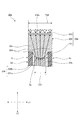
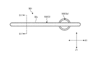
図9に示す本実施形態に係る車両表示装置用指針としての指針201は、指針発光体3にかえて指針発光体203を備える点で上述の指針1と異なり、その他の構成は、当該指針1とほぼ同様の構成である。
9 differs from the above-described pointer 1 in that it includes a pointer light emitter 203 in place of the pointer light emitter 3, and other configurations are the same. The configuration is almost the same.
指針発光体203は、第1光透過体としての指針プリズム部材231、第2光透過体としての光透過性キャップ232、及び、拡散層233を有し、これらが組み合わせられることで構成される。
The pointer light emitter 203 includes a pointer prism member 231 as a first light transmissive body, a light transmissive cap 232 as a second light transmissive body, and a diffusion layer 233, and these are combined.
指針プリズム部材231は、第1出射面31eにかえて第1出射面231eを含んで構成される点で上述の指針プリズム部材31と異なり、その他の構成は、当該指針プリズム部材31とほぼ同様の構成である。第1出射面231eは、本体部31bにおいて、指針光軸方向Y1に対して軸部31a(図5等参照)側とは反対側の面、ここでは、奥行き方向Y前面側の面によって構成される。本実施形態の第1出射面231eは、後述する入射面232bと共に光を屈折させて発散させるレンズを構成するように湾曲して曲面状に形成される。ここでは、第1出射面231eは、指針光軸方向Y1、及び、指針幅方向Z1に沿った断面視(図9参照)にて(言い換えれば、指針延在方向X1に視て)、指針光軸方向Y1に対して後述する入射面232bとは反対側、すなわち、軸部31a側に陥没した凹部状の略半円弧状に形成される。
The pointer prism member 231 is different from the above-described pointer prism member 31 in that the pointer prism member 231 includes the first emission surface 231e instead of the first emission surface 31e, and other configurations are substantially the same as those of the pointer prism member 31. It is a configuration. The first emission surface 231e is configured by a surface of the main body portion 31b opposite to the shaft portion 31a (see FIG. 5 and the like) side with respect to the pointer optical axis direction Y1, in this case, the surface on the front side in the depth direction Y. The The first exit surface 231e of the present embodiment is curved and formed in a curved surface so as to constitute a lens that refracts and diverges light together with an entrance surface 232b described later. Here, the first exit surface 231e is shown in cross-sectional view (see FIG. 9) along the pointer optical axis direction Y1 and the pointer width direction Z1 (in other words, as viewed in the pointer extending direction X1). It is formed in a substantially semicircular shape in a concave shape that is depressed on the side opposite to the incident surface 232b described later with respect to the axial direction Y1, that is, on the side of the shaft portion 31a.
光透過性キャップ232は、入射面32bにかえて入射面232bを、第2出射面32cにかえて第2出射面232cを含んで構成される点で上述の光透過性キャップ32と異なり、その他の構成は、当該光透過性キャップ32とほぼ同様の構成である。入射面232bは、本体部32aにおいて、指針光軸方向Y1に対して第1出射面231eと対向する面、ここでは、奥行き方向Y背面側の面によって構成される。本実施形態の入射面232bは、上述した第1出射面231eと共に光を屈折させて発散させるレンズを構成するように湾曲して曲面状に形成される。ここでは、入射面232bは、指針光軸方向Y1、及び、指針幅方向Z1に沿った断面視(図9参照)にて(言い換えれば、指針延在方向X1に視て)、指針光軸方向Y1に対して第2出射面232cとは反対側、すなわち、第1出射面231e側に突出した凸部状の略半円弧状に形成される。第2出射面232cは、本体部32aにおいて、指針光軸方向Y1に対して指針プリズム部材231の第1出射面231eと対向する面とは反対側の面、ここでは、奥行き方向Y前面側の面によって構成される。本実施形態の第2出射面232cは、平坦面として形成される。
The light transmissive cap 232 is different from the above-described light transmissive cap 32 in that the light transmissive cap 232 includes the light incident surface 232b instead of the light incident surface 32b, and includes the second light output surface 232c instead of the second light output surface 32c. The configuration is substantially the same as that of the light transmissive cap 32. The entrance surface 232b is configured by a surface facing the first exit surface 231e with respect to the pointer optical axis direction Y1 in the main body portion 32a, here, a surface on the back side in the depth direction Y. The incident surface 232b of the present embodiment is curved and formed in a curved surface so as to constitute a lens that refracts and diverges light together with the first emission surface 231e described above. Here, the entrance surface 232b is in the direction of the pointer optical axis in the cross-sectional view (see FIG. 9) along the pointer optical axis direction Y1 and the pointer width direction Z1 (in other words, as viewed in the pointer extending direction X1). It is formed in a substantially semicircular shape with a convex shape that protrudes on the opposite side of Y1 from the second emission surface 232c, that is, on the first emission surface 231e side. The second emission surface 232c is a surface of the main body portion 32a opposite to the surface facing the first emission surface 231e of the pointer prism member 231 with respect to the pointer optical axis direction Y1, here, the depth direction Y front side. Consists of faces. The second emission surface 232c of the present embodiment is formed as a flat surface.
拡散層233は、上述した拡散層33と同様に、光を拡散させる層である。本実施形態の拡散層233は、光透過性キャップ232の第2出射面232cに密着して設けられ、当該第2出射面232cから出射された光を拡散させる。より詳細には、拡散層233は、第2出射面232cの指針光軸方向Y1前方側の面に密着して設けられる。拡散層233は、上述した拡散層33と同様に、例えば、ホットスタンプ印刷、塗料の複数回の塗布、フィルム転写法等によって透光性着色層として構成され当該透光性着色層に着色された色によって指針発光体203の発光色(表示色)を自由に設定することができる。ここでは、拡散層233は、白色の透光性着色層として構成される。
Similar to the diffusion layer 33 described above, the diffusion layer 233 is a layer that diffuses light. The diffusion layer 233 of this embodiment is provided in close contact with the second emission surface 232c of the light transmissive cap 232, and diffuses the light emitted from the second emission surface 232c. More specifically, the diffusion layer 233 is provided in close contact with the surface on the front side in the pointer optical axis direction Y1 of the second emission surface 232c. Similar to the diffusion layer 33 described above, the diffusion layer 233 is configured as a light-transmitting colored layer by, for example, hot stamp printing, coating a plurality of times, a film transfer method, and the like, and the light-transmitting colored layer is colored. The emission color (display color) of the pointer light emitter 203 can be freely set depending on the color. Here, the diffusion layer 233 is configured as a white translucent colored layer.
そして、指針プリズム部材231と光透過性キャップ232とは、屈折率が相互に異なる光透過性材料によって構成される。指針プリズム部材231と光透過性キャップ232とは、入射面232bと第1出射面231eとが密着して設けられ当該第1出射面231eと当該入射面232bとが湾曲して形成される。指針プリズム部材231と光透過性キャップ232とは、例えば、屈折率が相互に異なる光透過性材料によって入射面232bと第1出射面231eとが密着した状態となるように二色成形により一体で形成される。
The pointer prism member 231 and the light transmissive cap 232 are made of light transmissive materials having different refractive indexes. The pointer prism member 231 and the light-transmitting cap 232 are formed such that the entrance surface 232b and the first exit surface 231e are in close contact, and the first exit surface 231e and the entrance surface 232b are curved. The pointer prism member 231 and the light transmissive cap 232 are integrally formed by, for example, two-color molding so that the incident surface 232b and the first emission surface 231e are in close contact with light transmissive materials having different refractive indexes. It is formed.
本実施形態の指針プリズム部材231と光透過性キャップ232とは、指針プリズム部材231の屈折率が相対的に大きく、光透過性キャップ232の屈折率が相対的に小さくなるような組み合わせで、屈折率が相互に異なる光透過性材料によって二色成形により一体で形成される。そして、指針プリズム部材231と光透過性キャップ232とは、入射面232bと第1出射面231eとが密着することで界面234を構成する。本実施形態の界面234は、光を屈折させて発散させるレンズを構成するように、第1出射面231e、及び、入射面232bの湾曲に応じて曲面状に形成される。ここでは、界面234は、指針光軸方向Y1、及び、指針幅方向Z1に沿った断面視(図9参照)にて(言い換えれば、指針延在方向X1に視て)、光透過性キャップ232から視て、指針光軸方向Y1に対して第2出射面232cとは反対側、すなわち、第1出射面231e側に突出した凸部状の略半円弧状に形成される。言い換えれば、界面234は、当該断面視にて、指針プリズム部材231から視て、指針光軸方向Y1に対して入射面232bとは反対側、すなわち、軸部31a側に陥没した凹部状の略半円弧状に形成される。つまり、界面234は、指針光軸方向Y1に対して指針光軸方向Y1の背面側に向けて突出した略半円弧状に形成される。
The pointer prism member 231 and the light transmissive cap 232 of this embodiment are refracted in such a combination that the refractive index of the pointer prism member 231 is relatively large and the refractive index of the light transmissive cap 232 is relatively small. It is integrally formed by two-color molding with light-transmitting materials having different rates. The pointer prism member 231 and the light transmissive cap 232 form an interface 234 when the incident surface 232b and the first emission surface 231e are in close contact with each other. The interface 234 of this embodiment is formed in a curved surface shape according to the curvature of the first exit surface 231e and the entrance surface 232b so as to constitute a lens that refracts and diverges light. Here, the interface 234 is a light-transmitting cap 232 in a cross-sectional view (see FIG. 9) along the pointer optical axis direction Y1 and the pointer width direction Z1 (in other words, viewed in the pointer extending direction X1). Viewed from the side of the pointer optical axis direction Y1, it is formed in a convex semi-circular arc shape that protrudes on the opposite side of the second emission surface 232c, that is, on the first emission surface 231e side. In other words, the interface 234 is a substantially concave shape that is depressed on the side opposite to the entrance surface 232b with respect to the pointer optical axis direction Y1, that is, on the side of the shaft portion 31a when viewed from the pointer prism member 231 in the cross-sectional view. It is formed in a semicircular arc shape. That is, the interface 234 is formed in a substantially semicircular arc shape protruding toward the back side of the pointer optical axis direction Y1 with respect to the pointer optical axis direction Y1.
上記のように構成される指針201は、光透過性キャップ232が少なくとも指針幅方向Z1に対して、第2出射面232cによる光の出射領域T22を第1出射面231eによる光の出射領域T21より広げて当該第2出射面232cから光を出射する。本実施形態の光透過性キャップ232は、光の屈折効果により第2出射面232cによる光の出射領域を広げる。ここでは、指針プリズム部材231と光透過性キャップ232とは、上述したように、屈折率が相互に異なる光透過性材料によって構成され入射面232bと第1出射面231eとが密着して設けられ、入射面232bと第1出射面231eとが湾曲して形成されることで、入射面232bと第1出射面231eとの界面234が屈折面を構成する。これにより、指針プリズム部材231と光透過性キャップ232とは、光を屈折させて発散させるレンズを構成し、当該レンズの光の屈折効果により第2出射面232cによる光の出射領域T22を第1出射面231eによる光の出射領域T21より広げる。
In the pointer 201 configured as described above, the light-transmitting cap 232 has at least the light emission region T22 by the second emission surface 232c in the pointer width direction Z1 than the light emission region T21 by the first emission surface 231e. The light is spread and emitted from the second emission surface 232c. The light transmissive cap 232 of the present embodiment widens the light emission region by the second emission surface 232c by the light refraction effect. Here, as described above, the pointer prism member 231 and the light transmissive cap 232 are made of light transmissive materials having different refractive indexes, and the entrance surface 232b and the first exit surface 231e are provided in close contact with each other. Since the entrance surface 232b and the first exit surface 231e are formed to be curved, the interface 234 between the entrance surface 232b and the first exit surface 231e constitutes a refracting surface. As a result, the pointer prism member 231 and the light-transmitting cap 232 constitute a lens that refracts and diverges light, and the light exit region T22 by the second exit surface 232c is defined as the first by the light refraction effect of the lens. It spreads from the light emission region T21 by the emission surface 231e.
以上で説明した指針201、車両表示装置100は、指針発光体203において、指針プリズム部材231に入射した光が第1出射面231eから指針光軸方向Y1に沿って出射され、光透過性キャップ232に入射し第2出射面232cから指針光軸方向Y1に沿って出射されることで指針発光体203の全体が発光する。このとき、指針201、車両表示装置100は、指針キャップ5の側壁部5d等によって指針プリズム部材231から指針幅方向Z1に沿って漏れる光が遮光されることで指針光軸方向Y1前面側への発光領域以外の発光領域を限定し指針発光体203の輪郭をシャープに見せることができる。その上で、指針201、車両表示装置100は、拡散層233による光の拡散、及び、光透過性キャップ232の第2出射面232cによる出射領域T22の拡大によって指針発光体203における発光領域を広げることができる。この結果、指針201、車両表示装置100は、適正に指針201の発光領域を広げることができる。
In the pointer 201 and the vehicle display device 100 described above, in the pointer light emitter 203, the light incident on the pointer prism member 231 is emitted from the first emission surface 231e along the pointer optical axis direction Y1, and the light transmitting cap 232 is emitted. Is incident on the second emission surface 232c and emitted along the pointer optical axis direction Y1, so that the entire pointer luminous body 203 emits light. At this time, in the pointer 201 and the vehicle display device 100, light leaking from the pointer prism member 231 along the pointer width direction Z1 is shielded by the side wall portion 5d of the pointer cap 5, etc., thereby moving the pointer optical axis direction Y1 front side. By limiting the light emitting area other than the light emitting area, the outline of the pointer light emitter 203 can be made sharp. In addition, the pointer 201 and the vehicle display device 100 widen the light emitting region of the pointer light emitter 203 by diffusing light by the diffusion layer 233 and expanding the emission region T22 by the second emission surface 232c of the light transmitting cap 232. be able to. As a result, the pointer 201 and the vehicle display device 100 can appropriately widen the light emission area of the pointer 201.
さらに、以上で説明した指針201、車両表示装置100によれば、拡散層233は、第2出射面232cに密着して設けられ、指針プリズム部材231と光透過性キャップ232とは、屈折率が相互に異なる光透過性材料によって構成され第1出射面231eから出射された光が入射する光透過性キャップ232の入射面232bと第1出射面231eとが密着して設けられ、当該第1出射面231eと当該入射面232bとが湾曲して形成される。したがって、指針201、車両表示装置100は、指針プリズム部材231の第1出射面231eと光透過性キャップ232の入射面232bとの界面234が屈折面を構成し当該指針プリズム部材231、光透過性キャップ232が光を屈折させて発散させるレンズとして構成されるので、当該レンズの光の屈折効果により第2出射面232cによる光の出射領域T22を第1出射面231eによる光の出射領域T21より広げることができる。またこの場合、指針201、車両表示装置100は、奥行き方向Y前面側の意匠面として機能する光透過性キャップ232の第2出射面232cを平坦面として形成することができる。
Furthermore, according to the pointer 201 and the vehicle display device 100 described above, the diffusion layer 233 is provided in close contact with the second emission surface 232c, and the refractive index of the pointer prism member 231 and the light transmitting cap 232 is low. An incident surface 232b of the light transmissive cap 232, which is made of different light transmissive materials and receives light emitted from the first emission surface 231e, is provided in close contact with the first emission surface 231e. The surface 231e and the incident surface 232b are formed to be curved. Therefore, in the pointer 201 and the vehicle display device 100, the interface 234 between the first emission surface 231e of the pointer prism member 231 and the incident surface 232b of the light transmissive cap 232 forms a refractive surface, and the pointer prism member 231 and the light transmissive Since the cap 232 is configured as a lens that refracts and diverges light, the light emission region T22 by the second emission surface 232c is wider than the light emission region T21 by the first emission surface 231e due to the light refraction effect of the lens. be able to. In this case, the pointer 201 and the vehicle display device 100 can form the second emission surface 232c of the light transmissive cap 232 functioning as a design surface on the front side in the depth direction Y as a flat surface.
なお、以上の説明では、指針プリズム部材231と光透過性キャップ232とは、入射面232bと第1出射面231eとが密着して界面234を構成するように二色成形等により一体で形成されるものとして説明したがこれに限らず、例えば、相互に別個に形成した上で溶着等によって一体化されてもよい。
In the above description, the pointer prism member 231 and the light transmitting cap 232 are integrally formed by two-color molding or the like so that the entrance surface 232b and the first exit surface 231e are in close contact to form the interface 234. Although described as a thing, it is not restricted to this, For example, after forming separately, you may integrate by welding etc.
また、以上で説明した界面234は、光を屈折させて発散させるレンズを構成するように、第1出射面231e、及び、入射面232bの湾曲に応じて曲面状に形成されるものとして説明したがこれに限らない。界面234は、光を屈折させて発散させるレンズを構成するように屈曲して多角形状に形成されてもよい。この場合、界面234は、指針光軸方向Y1、及び、指針幅方向Z1に沿った断面視にて(言い換えれば、指針延在方向X1に視て)、指針光軸方向Y1に対して指針光軸方向Y1の背面側に向けて突出し、指針光軸方向Y1に対して傾斜した複数の傾斜面によって略台形状に形成されてもよい。
Further, the interface 234 described above is described as being formed in a curved surface shape according to the curvature of the first exit surface 231e and the entrance surface 232b so as to constitute a lens that refracts and diverges light. However, it is not limited to this. The interface 234 may be bent and formed in a polygonal shape so as to constitute a lens that refracts and diverges light. In this case, the interface 234 indicates the pointer light with respect to the pointer optical axis direction Y1 in a sectional view along the pointer optical axis direction Y1 and the pointer width direction Z1 (in other words, as viewed in the pointer extending direction X1). It may be formed in a substantially trapezoid shape by a plurality of inclined surfaces that protrude toward the back side in the axial direction Y1 and are inclined with respect to the pointer optical axis direction Y1.
また、界面234の湾曲方向は、以上で説明したものに限らない。図10に示す変形例に係る車両表示装置用指針としての指針201Aは、第1光透過体としての指針プリズム部材231Aと第2光透過体としての光透過性キャップ232Aとの屈折率の大小関係が上述とは逆となっている。すなわち、指針プリズム部材231Aと光透過性キャップ232Aとは、光透過性キャップ232Aの屈折率が相対的に大きく、指針プリズム部材231Aの屈折率が相対的に小さくなるような組み合わせで、屈折率が相互に異なる光透過性材料によって二色成形により一体で形成される。
Further, the bending direction of the interface 234 is not limited to that described above. A pointer 201A as a guide for a vehicle display device according to the modification shown in FIG. 10 is a refractive index relationship between a pointer prism member 231A as a first light transmitting member and a light transmitting cap 232A as a second light transmitting member. Is the opposite of the above. In other words, the pointer prism member 231A and the light transmissive cap 232A are combined in such a way that the refractive index of the light transmissive cap 232A is relatively large and the refractive index of the pointer prism member 231A is relatively small. It is integrally formed by two-color molding with mutually different light transmissive materials.
そして、指針プリズム部材231Aと光透過性キャップ232Aとは、光透過性キャップ232Aの入射面232bAと指針プリズム部材231Aの第1出射面231eAとが密着することで界面234Aを構成する。第1出射面231eAは、指針光軸方向Y1、及び、指針幅方向Z1に沿った断面視(図10参照)にて(言い換えれば、指針延在方向X1に視て)、指針光軸方向Y1に対して入射面232bA側に突出した凸部状の略半円弧状に形成される。入射面232bAは、当該断面視にて、指針光軸方向Y1に対して第2出射面232c側に陥没した凹部状の略半円弧状に形成される。そして、界面234Aは、光を屈折させて発散させるレンズを構成するように、第1出射面231eA、及び、入射面232bAの湾曲に応じて曲面状に形成される。界面234Aは、指針光軸方向Y1、及び、指針幅方向Z1に沿った断面視にて(言い換えれば、指針延在方向X1に視て)、指針プリズム部材231Aから視て、指針光軸方向Y1に対して第2出射面232c側に突出した凸部状の略半円弧状に形成される。言い換えれば、界面234Aは、当該断面視にて、光透過性キャップ232Aから視て、指針光軸方向Y1に対して第2出射面232c側に陥没した凹部状の略半円弧状に形成される。つまり、界面234Aは、指針光軸方向Y1に対して指針光軸方向Y1の前面側に向けて突出した略半円弧状に形成される。
The pointer prism member 231A and the light transmissive cap 232A form an interface 234A when the incident surface 232bA of the light transmissive cap 232A and the first emission surface 231eA of the pointer prism member 231A are in close contact with each other. The first emission surface 231eA is in the pointer optical axis direction Y1 in a sectional view (see FIG. 10) along the pointer optical axis direction Y1 and the pointer width direction Z1 (in other words, viewed in the pointer extending direction X1). Is formed in a substantially semicircular shape with a convex shape protruding toward the incident surface 232bA. The incident surface 232bA is formed in a substantially semicircular shape having a concave shape that is recessed toward the second exit surface 232c with respect to the pointer optical axis direction Y1 in the cross-sectional view. The interface 234A is formed in a curved shape according to the curvature of the first exit surface 231eA and the entrance surface 232bA so as to constitute a lens that refracts and diverges light. The interface 234A is viewed in cross section along the pointer optical axis direction Y1 and the pointer width direction Z1 (in other words, viewed in the pointer extending direction X1), and viewed from the pointer prism member 231A, the pointer optical axis direction Y1. On the other hand, it is formed in a convex semi-circular arc shape protruding toward the second emission surface 232c. In other words, the interface 234A is formed in a substantially semicircular arc shape that is recessed in the second light exit surface 232c side with respect to the pointer optical axis direction Y1 when viewed from the light transmitting cap 232A in the cross-sectional view. . That is, the interface 234A is formed in a substantially semicircular arc shape protruding toward the front side in the pointer optical axis direction Y1 with respect to the pointer optical axis direction Y1.
この場合であっても、指針201Aは、指針プリズム部材231Aの第1出射面231eAと光透過性キャップ232Aの入射面232bAとの界面234Aが屈折面を構成し当該指針プリズム部材231A、光透過性キャップ232Aが光を屈折させて発散させるレンズとして構成されるので、当該レンズの光の屈折効果により第2出射面232cによる光の出射領域T22を第1出射面231eAによる光の出射領域T21より広げることができる。
Even in this case, in the pointer 201A, the interface 234A between the first emission surface 231eA of the pointer prism member 231A and the incident surface 232bA of the light transmissive cap 232A constitutes a refracting surface, and the pointer prism member 231A, light transmissive Since the cap 232A is configured as a lens that refracts and diverges the light, the light emission region T22 by the second emission surface 232c is wider than the light emission region T21 by the first emission surface 231eA by the light refraction effect of the lens. be able to.
[実施形態3]
実施形態3に係る車両表示装置用指針、及び、車両表示装置は、指針発光体の構成が実施形態1、2とは異なる。
[Embodiment 3]
The pointer for a vehicle display device and the vehicle display device according to the third embodiment are different from the first and second embodiments in the configuration of the pointer light emitter.
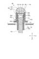
図11に示す本実施形態に係る車両表示装置用指針としての指針301は、指針発光体3にかえて指針発光体303を備える点で上述の指針1と異なり、その他の構成は、当該指針1とほぼ同様の構成である。
A pointer 301 as a guide for a vehicle display device according to the present embodiment shown in FIG. 11 is different from the above-described pointer 1 in that a pointer light emitter 303 is provided in place of the pointer light emitter 3, and other configurations are the same. The configuration is almost the same.
指針発光体303は、第1光透過体としての指針プリズム部材31、第2光透過体としての光透過性キャップ332、及び、拡散層33を有し、これらが組み合わせられることで構成される。指針プリズム部材31、拡散層33は、上述と同様の構成である。
The pointer light emitter 303 includes a pointer prism member 31 as a first light transmissive body, a light transmissive cap 332 as a second light transmissive body, and a diffusion layer 33, and these are combined. The pointer prism member 31 and the diffusion layer 33 have the same configuration as described above.
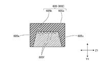
光透過性キャップ332は、第2出射面32cにかえて第2出射面332cを含んで構成される点で上述の光透過性キャップ32と異なり、その他の構成は、当該光透過性キャップ32とほぼ同様の構成である。第2出射面332cは、本体部32aにおいて、指針光軸方向Y1に対して指針プリズム部材31の第1出射面31eと対向する面とは反対側の面、ここでは、奥行き方向Y前面側の面によって構成される。
The light transmissive cap 332 is different from the light transmissive cap 32 in that the light transmissive cap 332 includes a second light emitting surface 332c instead of the second light emitting surface 32c. The configuration is almost the same. The second emission surface 332c is a surface of the main body portion 32a opposite to the surface facing the first emission surface 31e of the pointer prism member 31 with respect to the pointer optical axis direction Y1, in this case, in the depth direction Y front side. Consists of faces.
そして、本実施形態の光透過性キャップ332は、光の拡散効果により第2出射面332cによる光の出射領域を広げる。ここでは、光透過性キャップ332は、第2出射面332cが複数の微細凹凸部332fを有する。複数の微細凹凸部332fは、微細プリズム、あるいは、微細シボ形状に形成され、第2出射面332cから出射する光を拡散させる。複数の微細凹凸部332fは、凸状部分の断面形状が図12に示すように略三角形状の断面形状であってもよいし、図13に示すように略半円形状の断面形状であってもよい。複数の微細凹凸部332fは、指針延在方向X1、及び、指針幅方向Z1に沿って連続して形成される。これにより、光透過性キャップ332は、当該複数の微細凹凸部332fが形成された第2出射面332cが拡散層33とは異なる第2拡散面を構成し、当該第2拡散面を構成する第2出射面332cの光の拡散効果により第2出射面332cによる光の出射領域T32を第1出射面31eによる光の出射領域T31より広げる。
The light transmissive cap 332 of the present embodiment widens the light emission area by the second emission surface 332c due to the light diffusion effect. Here, in the light transmissive cap 332, the second emission surface 332c has a plurality of fine uneven portions 332f. The plurality of fine concavo-convex portions 332f are formed in a fine prism or fine grain shape, and diffuse light emitted from the second emission surface 332c. The plurality of fine concavo-convex portions 332f may have a substantially triangular cross-sectional shape as shown in FIG. 12, or a substantially semicircular cross-sectional shape as shown in FIG. Also good. The plurality of fine uneven portions 332f are continuously formed along the pointer extending direction X1 and the pointer width direction Z1. Accordingly, in the light transmissive cap 332, the second emission surface 332c on which the plurality of fine uneven portions 332f are formed constitutes a second diffusion surface different from the diffusion layer 33, and the second diffusion surface constitutes the second diffusion surface. Due to the light diffusion effect of the second emission surface 332c, the light emission region T32 by the second emission surface 332c is made wider than the light emission region T31 by the first emission surface 31e.
以上で説明した指針301、車両表示装置100は、指針発光体303において、指針プリズム部材31に入射した光が第1出射面31eから指針光軸方向Y1に沿って出射され、光透過性キャップ332に入射し第2出射面332cから指針光軸方向Y1に沿って出射されることで指針発光体303の全体が発光する。このとき、指針301、車両表示装置100は、指針キャップ5の側壁部5d等によって指針プリズム部材31から指針幅方向Z1に沿って漏れる光が遮光されることで指針光軸方向Y1前面側への発光領域以外の発光領域を限定し指針発光体303の輪郭をシャープに見せることができる。その上で、指針301、車両表示装置100は、拡散層33による光の拡散、及び、光透過性キャップ332の第2出射面332cによる出射領域T32の拡大によって指針発光体303における発光領域を広げることができる。この結果、指針301、車両表示装置100は、適正に指針301の発光領域を広げることができる。
In the pointer 301 and the vehicle display device 100 described above, in the pointer light emitter 303, the light incident on the pointer prism member 31 is emitted from the first emission surface 31e along the pointer optical axis direction Y1, and the light transmissive cap 332 is obtained. Is incident on the second emission surface 332c and emitted along the pointer optical axis direction Y1, so that the entire pointer luminous body 303 emits light. At this time, in the pointer 301 and the vehicle display device 100, light leaking from the pointer prism member 31 along the pointer width direction Z1 is shielded by the side wall portion 5d of the pointer cap 5, etc., thereby moving the pointer optical axis direction Y1 front side. By limiting the light emitting area other than the light emitting area, the outline of the pointer light emitter 303 can be made sharp. In addition, the pointer 301 and the vehicle display device 100 widen the light emitting region in the pointer light emitter 303 by diffusing light by the diffusion layer 33 and expanding the emission region T32 by the second emission surface 332c of the light transmissive cap 332. be able to. As a result, the pointer 301 and the vehicle display device 100 can appropriately widen the light emission area of the pointer 301.
さらに、以上で説明した指針301、車両表示装置100によれば、光透過性キャップ332は、光の拡散効果により第2出射面332cによる光の出射領域を広げる。したがって、指針301、車両表示装置100は、光透過性キャップ332が構成する光学系によって当該光透過性キャップ332に入射し第2出射面332cから出射される光を拡散させることで第2出射面332cによる光の出射領域T32を第1出射面31eによる光の出射領域T31より広げることができる。
Furthermore, according to the pointer 301 and the vehicle display device 100 described above, the light transmissive cap 332 widens the light emission region by the second emission surface 332c by the light diffusion effect. Therefore, the pointer 301 and the vehicle display device 100 diffuse the light that is incident on the light transmissive cap 332 and emitted from the second light emission surface 332c by the optical system that the light transmissive cap 332 is configured to have. The light emission region T32 by 332c can be made wider than the light emission region T31 by the first emission surface 31e.
さらに、以上で説明した指針301、車両表示装置100によれば、拡散層33は、第1出射面31eに密着して設けられ、光透過性キャップ332は、第1出射面31eから拡散層33を介して出射された光が入射する入射面32bが拡散層33との間に隙間32eを有して位置し、第2出射面332cが複数の微細凹凸部332fを有する。したがって、指針301、車両表示装置100は、複数の微細凹凸部332fが形成された第2出射面332cが拡散層33とは異なる第2拡散面を構成するので、当該第2拡散面を構成する第2出射面332cの光の拡散効果により第2出射面332cによる光の出射領域T32を第1出射面31eによる光の出射領域T31より広げることができる。
Furthermore, according to the pointer 301 and the vehicle display device 100 described above, the diffusion layer 33 is provided in close contact with the first emission surface 31e, and the light transmissive cap 332 is provided from the first emission surface 31e to the diffusion layer 33. The incident surface 32b on which the light emitted via the light enters is located with a gap 32e between the diffusion layer 33 and the second emission surface 332c has a plurality of fine uneven portions 332f. Therefore, in the pointer 301 and the vehicle display device 100, the second emission surface 332c on which the plurality of fine uneven portions 332f are formed constitutes a second diffusion surface different from the diffusion layer 33, and thus constitutes the second diffusion surface. Due to the light diffusion effect of the second emission surface 332c, the light emission region T32 by the second emission surface 332c can be made wider than the light emission region T31 by the first emission surface 31e.
なお、以上の説明では、光透過性キャップ332は、第2出射面332cが複数の微細凹凸部332fを有するものとして説明したがこれに限らない。図14に示す変形例に係る車両表示装置用指針としての指針301Aのように、光透過性キャップ332Aは、入射面32bが複数の微細凹凸部332fAを有していてもよい。複数の微細凹凸部332fAは、上述の微細凹凸部332fと同様の構成であり、指針延在方向X1、及び、指針幅方向Z1に沿って連続して形成される。これにより、光透過性キャップ332Aは、当該複数の微細凹凸部332fAが形成された入射面32bが拡散層33とは異なる第2拡散面を構成する。この場合であっても、指針301A、車両表示装置100は、当該第2拡散面を構成する入射面32bの光の拡散効果により第2出射面332cによる光の出射領域T32を第1出射面31eによる光の出射領域T31より広げることができる。
In the above description, the light-transmitting cap 332 is described as having the second exit surface 332c having a plurality of fine uneven portions 332f, but is not limited thereto. Like the pointer 301A as the pointer for the vehicle display device according to the modification shown in FIG. 14, the light transmitting cap 332A may have a plurality of fine uneven portions 332fA on the incident surface 32b. The plurality of fine uneven portions 332fA have the same configuration as the fine uneven portion 332f described above, and are continuously formed along the pointer extending direction X1 and the pointer width direction Z1. Accordingly, in the light transmissive cap 332A, the incident surface 32b on which the plurality of fine uneven portions 332fA are formed constitutes a second diffusion surface different from the diffusion layer 33. Even in this case, the pointer 301A and the vehicle display device 100 define the light emission region T32 by the second emission surface 332c as the first emission surface 31e by the light diffusion effect of the incident surface 32b constituting the second diffusion surface. The light emission region T31 can be expanded.
[実施形態4]
実施形態4に係る車両表示装置用指針、及び、車両表示装置は、指針遮光体の構成が実施形態1、2、3とは異なる。
[Embodiment 4]
The pointer for a vehicle display device and the vehicle display device according to the fourth embodiment are different from the first, second, and third embodiments in the configuration of the pointer light shielding body.
図15、図16、図17、図18に示す本実施形態に係る車両表示装置用指針としての指針401は、指針ステム2、指針キャップ5にかえて指針遮光体としての指針カバー405を備える点で上述の指針1と異なる。より具体的には、本実施形態の指針401は、指針発光体403と、バランサ4と、接続基部としても兼用される指針遮光体としての指針カバー405とを備え、回転軸106を介して導光された光によって指針発光体403の全体が発光する。バランサ4は、上述の構成と同様の構成である。
A pointer 401 as a pointer for a vehicle display device according to this embodiment shown in FIGS. 15, 16, 17, and 18 includes a pointer cover 405 as a pointer light shielding body instead of the pointer stem 2 and the pointer cap 5. And different from the above-mentioned guideline 1. More specifically, the pointer 401 of the present embodiment includes a pointer light emitter 403, a balancer 4, and a pointer cover 405 as a pointer light-shielding body that is also used as a connection base, and is guided through the rotation shaft 106. The whole pointer light emitter 403 emits light by the emitted light. The balancer 4 has the same configuration as that described above.
本実施形態の指針発光体403は、第1光透過体としての指針プリズム部材431、第2光透過体としての光透過性キャップ32、及び、拡散層33を有し、これらが組み合わせられることで構成される。指針プリズム部材431は、被支持部31c、及び、組み付け孔部31fを備えない点で、上述の指針プリズム部材31と異なり、その他の構成は、当該指針プリズム部材31とほぼ同様の構成である。光透過性キャップ32、及び、拡散層33は、上述の構成と同様の構成である。
The pointer light emitter 403 of this embodiment includes a pointer prism member 431 as a first light transmitter, a light-transmitting cap 32 as a second light transmitter, and a diffusion layer 33, which are combined. Composed. The pointer prism member 431 is different from the above-described pointer prism member 31 in that it does not include the supported portion 31c and the assembly hole portion 31f, and other configurations are substantially the same as those of the pointer prism member 31. The light transmissive cap 32 and the diffusion layer 33 have the same configuration as described above.
本実施形態の指針カバー405は、指針発光体403に装着され一部の光を遮光する遮光部材であると共に、回転軸106と指針発光体403とを接続し、指針発光体403を回転軸106に一体回転可能に支持する接続支持部材としても兼用される。指針カバー405は、遮光性材料によって指針延在方向X1に沿って延在して形成され、指針プリズム部材431を指針幅方向Z1の両側から覆い指針プリズム部材431から指針幅方向Z1に沿って漏れる光を遮光する。指針カバー405は、スリット部405a、回転軸接続部405b、及び、円板遮光部405cを含んで構成され、これらが光を遮光する遮光性の樹脂材料によって一体に形成される。
The pointer cover 405 of the present embodiment is a light-shielding member that is attached to the pointer light emitter 403 and shields part of the light, and connects the rotary shaft 106 and the pointer light emitter 403 to connect the pointer light emitter 403 to the rotary shaft 106. It is also used as a connection support member that is supported so as to be integrally rotatable. The pointer cover 405 is formed of a light shielding material so as to extend along the pointer extending direction X1, covers the pointer prism member 431 from both sides of the pointer width direction Z1, and leaks from the pointer prism member 431 along the pointer width direction Z1. Block out light. The pointer cover 405 includes a slit portion 405a, a rotary shaft connecting portion 405b, and a disc light shielding portion 405c, and these are integrally formed of a light shielding resin material that shields light.
スリット部405aは、底部405d、及び、側壁部405eを有し、底部405d、側壁部405eによって当該指針プリズム部材431の本体部31bを収容する中空状部405fが形成された部分である。底部405dは、指針延在方向X1に沿って延在する板状に形成された底体であり、指針光軸方向Y1の一方側の面に指針発光体403を支持する部分である。側壁部405eは、底部405dから指針光軸方向Y1の前面側に突出して延在しかつ指針延在方向X1に沿って延在して枠状に形成され、上記中空状部405fを区画する。言い換えれば、側壁部405eは、中空状部405fを囲うようにして底部405dから指針光軸方向Y1に沿って立設される壁体である。また、側壁部405eは、係止爪部405g(図18参照)を有する。係止爪部405gは、側壁部405eにおいて指針幅方向Z1に対向する各内壁面にそれぞれ1つずつ、合計2つが設けられる。各係止爪部405gは、各内壁面から突起状に形成され、指針プリズム部材431の導光中空部31dに嵌合し係止されることで、当該指針プリズム部材431を中空状部405f内に係止するものである。また、側壁部405eにおいて係止爪部405gが形成された内壁面、すなわち、指針幅方向Z1に対向する各内壁面は、指針光軸方向Y1の背面側から前面側に向かうにしたがって指針幅方向Z1に沿った幅が徐々に広がるような傾斜のテーパ面として構成される(図18参照)。中空状部405fは、底部405dと側壁部405eとによって区画される空間部であり、指針光軸方向Y1の前面側に開口する。スリット部405aは、上記中空状部405f内に指針プリズム部材431における本体部31bが収容された状態で、中空状部405fの開口から当該本体部31bの第1出射面31e、及び、拡散層33を指針光軸方向Y1前面側に露出させる。この状態で、各係止爪部405gは、指針プリズム部材431の導光中空部31dに嵌合し係止されることで、当該指針プリズム部材431を中空状部405f内に係止する。また、側壁部405eは、指針プリズム部材431を指針幅方向Z1の両側から覆い指針プリズム部材431から指針幅方向Z1に沿って漏れる光を遮光すると共に当該指針プリズム部材431を保持する。
The slit portion 405a is a portion having a bottom portion 405d and a side wall portion 405e, and a hollow portion 405f for accommodating the main body portion 31b of the pointer prism member 431 is formed by the bottom portion 405d and the side wall portion 405e. The bottom portion 405d is a bottom body formed in a plate shape extending along the pointer extending direction X1, and is a portion that supports the pointer light emitter 403 on one surface in the pointer optical axis direction Y1. The side wall portion 405e extends from the bottom portion 405d to the front side in the pointer optical axis direction Y1 and extends along the pointer extending direction X1, and is formed in a frame shape, thereby defining the hollow portion 405f. In other words, the side wall portion 405e is a wall body that stands up from the bottom portion 405d along the pointer optical axis direction Y1 so as to surround the hollow portion 405f. Moreover, the side wall part 405e has the latching claw part 405g (refer FIG. 18). A total of two locking claws 405g are provided on each inner wall surface facing the pointer width direction Z1 in the side wall portion 405e. Each latching claw portion 405g is formed in a protruding shape from each inner wall surface, and is fitted into and latched with the light guide hollow portion 31d of the pointer prism member 431 so that the pointer prism member 431 is placed in the hollow portion 405f. To be locked. Further, the inner wall surface in which the locking claw portion 405g is formed in the side wall portion 405e, that is, each inner wall surface that faces the pointer width direction Z1, extends in the pointer width direction from the back side to the front side in the pointer optical axis direction Y1. It is configured as an inclined taper surface whose width along Z1 gradually increases (see FIG. 18). The hollow portion 405f is a space portion defined by the bottom portion 405d and the side wall portion 405e, and opens to the front side in the pointer optical axis direction Y1. The slit portion 405a includes the first emission surface 31e of the main body portion 31b and the diffusion layer 33 from the opening of the hollow portion 405f in a state where the main body portion 31b of the pointer prism member 431 is accommodated in the hollow portion 405f. Is exposed to the front surface side in the direction Y1 of the pointer optical axis. In this state, each locking claw portion 405g is fitted and locked in the light guide hollow portion 31d of the pointer prism member 431, thereby locking the pointer prism member 431 in the hollow portion 405f. Further, the side wall portion 405e covers the pointer prism member 431 from both sides in the pointer width direction Z1, shields light leaking from the pointer prism member 431 along the pointer width direction Z1, and holds the pointer prism member 431.
回転軸接続部405bは、回転軸106に接続され、当該回転軸106と指針発光体403とを接続するいわゆる袴とも呼ばれる部分である。回転軸接続部405bは、内部が中空の円筒状に形成され、スリット部405aの底部405dから指針光軸方向Y1に沿って突出して形成される。回転軸接続部405bは、底部405dにおいて指針発光体403を支持する面とは反対側に突出して形成され、内部の中空状の部分が底部405dを貫通し、指針光軸方向Y1の両側に開口している(図17、図18等参照)。回転軸接続部405bは、内部の中空状の部分が中空状部405fの内部と連通する。回転軸接続部405bは、指針光軸方向Y1の一方の端部開口に回転軸106が嵌合され、指針光軸方向Y1の他方の端部開口に指針発光体403の軸部31aが嵌合されることで、回転軸106と軸部31aとを一体回転可能に接続する。
The rotating shaft connecting portion 405 b is a portion called a soot that is connected to the rotating shaft 106 and connects the rotating shaft 106 and the pointer light emitter 403. The rotary shaft connecting portion 405b is formed in a cylindrical shape having a hollow inside, and is formed to protrude from the bottom portion 405d of the slit portion 405a along the pointer optical axis direction Y1. The rotary shaft connecting portion 405b is formed to protrude on the side opposite to the surface supporting the pointer light emitter 403 at the bottom portion 405d, and an internal hollow portion passes through the bottom portion 405d and opens on both sides in the pointer optical axis direction Y1. (Refer to FIG. 17, FIG. 18, etc.). The rotary shaft connecting portion 405b communicates with the inside of the hollow portion 405f at the hollow portion inside. In the rotary shaft connecting portion 405b, the rotary shaft 106 is fitted into one end opening in the pointer optical axis direction Y1, and the shaft portion 31a of the pointer light emitter 403 is fitted into the other end opening in the pointer optical axis direction Y1. Thus, the rotary shaft 106 and the shaft portion 31a are connected so as to be integrally rotatable.
円板遮光部405cは、スリット部405aと回転軸接続部405bとの接続部分に略円盤状に形成される部分である。円板遮光部405cは、文字板103に形成された開口103aよりも大径に形成され、光源107から照射され当該開口103aを介して漏れる光を遮光し、当該漏れ光が運転者等の目視位置に至ることを規制する。
The disc light-shielding portion 405c is a portion that is formed in a substantially disc shape at the connection portion between the slit portion 405a and the rotating shaft connecting portion 405b. The disc light-shielding portion 405c is formed to have a larger diameter than the opening 103a formed in the dial plate 103, shields light that is emitted from the light source 107 and leaks through the opening 103a, and the leaked light is visually observed by a driver or the like. Regulate reaching position.
上記のように構成される指針401は、指針プリズム部材431の本体部31bと指針カバー405の底部405dとの間の所定の位置にバランサ4を介在させると共に、本体部31bが側壁部405eの間に嵌り第1出射面31e、拡散層33がスリット部405aの中空状部405fの開口から露出するような位置関係で、指針カバー405がバランサ4と共に指針プリズム部材431に装着される。この場合、指針401は、スリット部405aの中空状部405fの開口に対して指針光軸方向Y1の前面側からバランサ4、及び、指針プリズム部材431の軸部31a側が挿入されるようにして指針プリズム部材431とバランサ4と指針カバー405とが組み付けられ一体化される。このとき、指針401は、側壁部405eにおいて指針幅方向Z1に対向する各内壁面が上記のようなテーパ面として構成されていることから、指針プリズム部材431を中空状部405f内に挿入しやすい構成とすることができる。そして、指針401は、指針プリズム部材431とバランサ4と指針カバー405とが組み付けられた状態で、各係止爪部405gが導光中空部31dに嵌合し係止されることで当該指針プリズム部材431が中空状部405f内に係止されると共に、側壁部405eが指針プリズム部材431を指針幅方向Z1の両側から覆い当該指針プリズム部材431を保持する。そして、指針401は、光透過性キャップ32の突出縁部32dが側壁部405eの端面に密着しマウントされるようにして設けられる。ここでは、光透過性キャップ32は、例えば、接着剤を介した接着や溶着等により指針カバー405と一体化される。そして、指針401は、指針プリズム部材431とバランサ4と指針カバー405とが組み付けられた状態で、指針プリズム部材431が指針カバー405の底部405d上に支持され、軸部31aが指針カバー405の回転軸接続部405bに嵌合し回転軸106と一体回転可能に接続される。
The pointer 401 configured as described above interposes the balancer 4 at a predetermined position between the main body 31b of the pointer prism member 431 and the bottom 405d of the pointer cover 405, and the main body 31b is between the side wall 405e. The pointer cover 405 is attached to the pointer prism member 431 together with the balancer 4 in such a positional relationship that the first emission surface 31e and the diffusion layer 33 are exposed from the opening of the hollow portion 405f of the slit portion 405a. In this case, the pointer 401 is inserted so that the balancer 4 and the shaft portion 31a side of the pointer prism member 431 are inserted from the front side in the pointer optical axis direction Y1 with respect to the opening of the hollow portion 405f of the slit portion 405a. The prism member 431, the balancer 4, and the pointer cover 405 are assembled and integrated. At this time, in the pointer 401, each inner wall surface facing the pointer width direction Z1 in the side wall portion 405e is configured as a tapered surface as described above, so that the pointer prism member 431 can be easily inserted into the hollow portion 405f. It can be configured. The pointer 401 has the pointer prism member 431, the balancer 4, and the pointer cover 405 assembled thereto, and each locking claw portion 405g is fitted and locked to the light guide hollow portion 31d, thereby the pointer prism. The member 431 is locked in the hollow portion 405f, and the side wall portion 405e covers the pointer prism member 431 from both sides in the pointer width direction Z1, and holds the pointer prism member 431. The pointer 401 is provided such that the protruding edge portion 32d of the light transmissive cap 32 is mounted in close contact with the end surface of the side wall portion 405e. Here, the light transmissive cap 32 is integrated with the pointer cover 405 by, for example, adhesion or welding via an adhesive. In the state where the pointer prism member 431, the balancer 4, and the pointer cover 405 are assembled, the pointer 401 is supported on the bottom portion 405d of the pointer cover 405, and the shaft portion 31a is rotated by the pointer cover 405. The shaft is connected to the shaft connecting portion 405b so as to be integrally rotatable with the rotating shaft.
以上で説明した指針401、車両表示装置100は、指針発光体403において、指針プリズム部材431に入射した光が第1出射面31eから指針光軸方向Y1に沿って出射され、光透過性キャップ32に入射し第2出射面32cから指針光軸方向Y1に沿って出射されることで指針発光体403の全体が発光する。このとき、指針401、車両表示装置100は、指針カバー405の側壁部405e等によって指針プリズム部材431から指針幅方向Z1に沿って漏れる光が遮光されることで指針光軸方向Y1前面側への発光領域以外の発光領域を限定し指針発光体403の輪郭をシャープに見せることができる。その上で、指針401、車両表示装置100は、拡散層33による光の拡散、及び、光透過性キャップ32の第2出射面32cによる出射領域T12(図7等参照)の拡大によって指針発光体403における発光領域を広げることができる。この結果、指針401、車両表示装置100は、適正に指針401の発光領域を広げることができる。
In the pointer 401 and the vehicle display device 100 described above, in the pointer light emitter 403, the light incident on the pointer prism member 431 is emitted from the first emission surface 31e along the pointer optical axis direction Y1, and the light transmissive cap 32. Is incident on the second emission surface 32c and emitted along the pointer optical axis direction Y1, so that the entire pointer light emitter 403 emits light. At this time, in the pointer 401 and the vehicle display device 100, the light leaking from the pointer prism member 431 along the pointer width direction Z1 is shielded by the side wall portion 405e of the pointer cover 405 and the like to the front side of the pointer optical axis direction Y1. By limiting the light emitting area other than the light emitting area, the outline of the pointer light emitter 403 can be made sharp. In addition, the pointer 401 and the vehicle display device 100 are configured to emit the pointer light emitter by diffusing light by the diffusion layer 33 and expanding the emission region T12 (see FIG. 7 and the like) by the second emission surface 32c of the light transmissive cap 32. The light emitting region in 403 can be expanded. As a result, the pointer 401 and the vehicle display device 100 can appropriately widen the light emission area of the pointer 401.
さらに、以上で説明した指針401、車両表示装置100によれば、指針カバー405は、指針発光体403を指針幅方向Z1の両側から覆い当該指針発光体403を保持する側壁部405e、及び、回転駆動可能な回転軸106と接続される回転軸接続部405bを有し、側壁部405eと回転軸接続部405bとが一体で形成される。したがって、指針401、車両表示装置100は、指針発光体403を保持、遮光するための構成と、指針発光体403と回転軸106とを接続するための構成とを指針カバー405によって兼用することができるので、構成部品点数を抑制することができ、例えば、製造コストを抑制することができる。また、指針401、車両表示装置100は、例えば、上述した被支持部31c、組み付け孔部31f等の構成を備えなくてもよいことから、外形を小型化することができ、例えば、円板遮光部405cの外径を相対的に小径にすることがきるので、当該円板遮光部405cをより目立たなくすることができ、指針発光体403の輪郭のシャープ感を向上することができる。
Furthermore, according to the pointer 401 and the vehicle display device 100 described above, the pointer cover 405 covers the pointer light emitter 403 from both sides of the pointer width direction Z1, and the side wall portion 405e that holds the pointer light emitter 403, and the rotation. The rotating shaft connecting portion 405b is connected to the drivable rotating shaft 106, and the side wall portion 405e and the rotating shaft connecting portion 405b are integrally formed. Therefore, the pointer 401 and the vehicle display device 100 can share the configuration for holding and shielding the pointer light emitter 403 and the configuration for connecting the pointer light emitter 403 and the rotating shaft 106 by the pointer cover 405. Therefore, the number of component parts can be suppressed, and for example, the manufacturing cost can be suppressed. In addition, since the pointer 401 and the vehicle display device 100 do not have to include the above-described configuration of the supported portion 31c, the assembly hole portion 31f, and the like, for example, the outer shape can be reduced, and for example, the light shielding of the disc Since the outer diameter of the portion 405c can be made relatively small, the disc light-shielding portion 405c can be made less noticeable, and the sharpness of the contour of the pointer light emitter 403 can be improved.
また、以上で説明した指針401は、光透過性キャップ32が指針カバー405の側壁部405eにおける第1出射面31eによる光の出射側の端面を覆うように設けられることから、指針プリズム部材431と側壁部405eとの隙間をより視認し難くし目立たなくすることができる。
Further, the pointer 401 described above is provided so that the light transmissive cap 32 covers the end surface on the light emission side by the first emission surface 31e in the side wall portion 405e of the pointer cover 405. The gap with the side wall portion 405e is less visible and can be made inconspicuous.
[実施形態5]
実施形態5に係る車両表示装置用指針、及び、車両表示装置は、指針遮光体及び接続基部の構成が実施形態1、2、3、4とは異なる。
[Embodiment 5]
The pointer for a vehicle display device and the vehicle display device according to the fifth embodiment are different from those of the first, second, third, and fourth embodiments in the configuration of the pointer light shielding body and the connection base.
図19、図20、図21、図22、図23に示す本実施形態に係る車両表示装置用指針としての指針501は、指針ステム2、指針キャップ5にかえて接続基部としての指針ステム502、指針遮光体としての指針キャップ505を備える点で上述の指針1と異なる。その他の構成は、当該指針1とほぼ同様の構成である。
19, 20, 21, 22, and 23, a pointer 501 as a pointer for a vehicle display device according to the present embodiment includes a pointer stem 502 as a connection base instead of the pointer stem 2 and the pointer cap 5. It differs from the above-described pointer 1 in that it includes a pointer cap 505 as a pointer light shield. Other configurations are substantially the same as those of the pointer 1.
本実施形態の指針ステム502は、回転軸106と指針発光体3とを接続し、指針発光体3を回転軸106に一体回転可能に支持する接続支持部材である。指針ステム502は、基部521、円筒軸部22、及び、バランサ支持部21bを含んで構成され、これらが光を遮光する遮光性の樹脂材料によって一体に形成される。
The pointer stem 502 of the present embodiment is a connection support member that connects the rotary shaft 106 and the pointer light emitter 3 and supports the pointer light emitter 3 on the rotary shaft 106 so as to be integrally rotatable. The pointer stem 502 includes a base portion 521, a cylindrical shaft portion 22, and a balancer support portion 21b, and these are integrally formed of a light-blocking resin material that blocks light.
基部521は、指針延在方向X1に沿って延在する板状に形成され指針光軸方向Y1の一方側の面に指針発光体3を支持する部分である。基部521は、円筒軸部22が接続される部分が略円形板状に形成された円形板部21gを有し、当該円形板部21gに組み付け孔部21aが形成される(図20等参照)。組み付け孔部21aは、指針キャップ505が組み付けられる部分であり、ここでは、2つ設けられる。基部521は、指針プリズム部材31の本体部31bを支持するプリズム支持部21cが複数、例えば、2つ設けられる。各プリズム支持部21cは、円形板部21gよりも指針501の指針延在方向X1の先端側に設けられ、基部521の指針光軸方向Y1の前面側に突出して形成される。各プリズム支持部21cは、指針プリズム部材31の本体部31bの突出量が多い側を支持する。
The base 521 is a portion that is formed in a plate shape extending along the pointer extending direction X1 and that supports the pointer light emitter 3 on one surface in the pointer optical axis direction Y1. The base 521 has a circular plate portion 21g in which a portion to which the cylindrical shaft portion 22 is connected is formed in a substantially circular plate shape, and an assembly hole portion 21a is formed in the circular plate portion 21g (see FIG. 20 and the like). . The assembly hole 21a is a part to which the pointer cap 505 is assembled, and two are provided here. The base portion 521 is provided with a plurality of, for example, two prism support portions 21 c that support the main body portion 31 b of the pointer prism member 31. Each prism support portion 21c is provided on the distal end side in the pointer extending direction X1 of the pointer 501 with respect to the circular plate portion 21g, and is formed to protrude to the front side in the pointer optical axis direction Y1 of the base portion 521. Each prism support portion 21c supports the side where the main body portion 31b of the pointer prism member 31 has a large amount of protrusion.
バランサ支持部21bは、バランサ4を支持する部分であり、円形板部21gの指針延在方向X1の後端側に連結部21hを介して設けられる。バランサ支持部21bは、底部21eと、側壁部21dとを有する。底部21eは、指針延在方向X1に沿って延在し板状に形成される。底部21eは、バランサ4が載置される。側壁部21dは、底部21eから指針光軸方向Y1の前面側に突出して延在しかつ指針延在方向X1に沿って延在して枠状に形成され、中空状部21fを区画する。言い換えれば、側壁部21dは、中空状部21fを囲うようにして指針光軸方向Y1に沿って立設される壁体である。中空状部21fは、バランサ4の一部を収容する。中空状部21fは、例えば、バランサ4の指針光軸方向Y1の端部側を収容する。
The balancer support portion 21b is a portion that supports the balancer 4, and is provided on the rear end side of the pointer extending direction X1 of the circular plate portion 21g via a connecting portion 21h. The balancer support portion 21b has a bottom portion 21e and a side wall portion 21d. The bottom 21e extends along the pointer extending direction X1 and is formed in a plate shape. The balancer 4 is placed on the bottom 21e. The side wall portion 21d extends from the bottom portion 21e to the front side in the pointer optical axis direction Y1 and extends along the pointer extending direction X1, and is formed in a frame shape, thereby defining the hollow portion 21f. In other words, the side wall portion 21d is a wall body that is erected along the pointer optical axis direction Y1 so as to surround the hollow portion 21f. The hollow portion 21 f accommodates a part of the balancer 4. The hollow portion 21f accommodates, for example, the end portion side of the balancer 4 in the pointer optical axis direction Y1.
指針キャップ505は、遮光性材料によって指針延在方向X1に沿って延在して形成され、指針プリズム部材31を指針幅方向Z1の両側から覆い指針プリズム部材31から指針幅方向Z1に沿って漏れる光を遮光する。また、指針キャップ505は、バランサ支持部21bに一部が収容されたバランサ4に指針光軸方向Y1の前面側から覆い被さり、当該バランサ4の露出した部分を覆う。指針キャップ505は、軸部カバー部5a、スリット部505bを含んで構成され、これらが光を遮光する遮光性の樹脂材料によって一体に形成される。
The pointer cap 505 is formed of a light-shielding material so as to extend along the pointer extending direction X1, covers the pointer prism member 31 from both sides of the pointer width direction Z1, and leaks from the pointer prism member 31 along the pointer width direction Z1. Block out light. The pointer cap 505 covers the balancer 4 partially accommodated in the balancer support portion 21b from the front side in the pointer optical axis direction Y1, and covers the exposed portion of the balancer 4. The pointer cap 505 includes a shaft cover portion 5a and a slit portion 505b, and these are integrally formed of a light-blocking resin material that blocks light.
スリット部505bは、側壁部505dを有し、当該側壁部505dによって指針プリズム部材31の本体部31b、及び、バランサ4の露出部を収容する中空状部505eが形成された部分である。側壁部505dは、軸部カバー部5aから指針光軸方向Y1の前面側に突出して延在しかつ指針延在方向X1に沿って延在して枠状に形成される。側壁部505dは、指針延在方向X1において軸部カバー部5aよりも前方側に設けられる前方壁部505f、及び、指針延在方向X1において軸部カバー部5aよりも後方側に設けられる後方壁部505gを含んで構成される。前方壁部505fは、指針延在方向X1において指針プリズム部材31の本体部31bの突出量が多い側を囲う部分である。後方壁部505gは、指針延在方向X1において指針プリズム部材31の本体部31bの突出量が少ない側を囲うと共にバランサ4の露出部分を囲う部分である。
The slit portion 505b has a side wall portion 505d, and the side wall portion 505d is a portion where the main body portion 31b of the pointer prism member 31 and the hollow portion 505e that accommodates the exposed portion of the balancer 4 are formed. The side wall portion 505d extends from the shaft portion cover portion 5a to the front side in the pointer optical axis direction Y1 and extends along the pointer extending direction X1, and is formed in a frame shape. The side wall portion 505d includes a front wall portion 505f provided on the front side of the shaft portion cover portion 5a in the pointer extending direction X1 and a rear wall provided on the rear side of the shaft portion cover portion 5a in the pointer extending direction X1. Part 505g. The front wall portion 505f is a portion that surrounds the side where the main body portion 31b of the pointer prism member 31 has a large amount of protrusion in the pointer extending direction X1. The rear wall portion 505g is a portion that surrounds the side where the main body portion 31b of the pointer prism member 31 projects less in the pointer extending direction X1 and the exposed portion of the balancer 4.
後方壁部505gは、指針キャップ505が指針ステム502に装着された状態で、指針光軸方向Y1の指針ステム502側の端部505hが、上記バランサ支持部21bの側壁部21dの指針光軸方向Y1の指針キャップ505側の端部21iに当接する(図23参照)。すなわち、後方壁部505gは、指針キャップ505が指針ステム502に装着された状態で、バランサ支持部21bに被らずにバランサ4の露出部分を指針幅方向Z1の両側から囲う。言い換えれば、後方壁部505gは、指針キャップ505が指針ステム502に装着された状態で、バランサ支持部21bの側壁部21dに対し指針幅方向Z1にオーバーラップせずにバランサ4の露出部分を指針幅方向Z1の両側から囲う。この構成により、指針501は、従来のように後方壁部505gをバランサ支持部21bに被らせる場合と比較して、指針キャップ505の指針幅方向Z1の幅サイズを小さくすることができ、意匠性を向上させることができる。後方壁部505gの指針幅方向Z1の間隔W1は、バランサ支持部21bの側壁部21dの間隔W2よりも大きい(図23参照)。つまり、指針キャップ505の後方壁部505gは、運転者等の目視位置から視認した場合に、バランサ支持部21bの側壁部21dを覆う。この構成により、指針501は、運転者等の目視位置から視認した場合に、指針キャップ505の後方壁部505gとバランサ支持部21bの側壁部21dとの境界が目立つことを抑制することができ、意匠性を向上することができる。なお、指針501は、指針キャップ505の後方壁部505gの色とバランサ支持部21bの側壁部21dの色とを同色とすることで、これらの境界が目立つことをより抑制することができる。
In the state where the pointer cap 505 is attached to the pointer stem 502, the rear wall portion 505g has an end portion 505h on the pointer stem 502 side in the pointer optical axis direction Y1 in the pointer optical axis direction of the side wall portion 21d of the balancer support portion 21b. It contacts the end 21i of Y1 on the pointer cap 505 side (see FIG. 23). That is, the rear wall portion 505g surrounds the exposed portion of the balancer 4 from both sides in the pointer width direction Z1 without being covered by the balancer support portion 21b in a state where the pointer cap 505 is attached to the pointer stem 502. In other words, the rear wall portion 505g indicates the exposed portion of the balancer 4 without overlapping the side wall portion 21d of the balancer support portion 21b in the pointer width direction Z1 with the pointer cap 505 attached to the pointer stem 502. Enclose from both sides in the width direction Z1. With this configuration, the pointer 501 can reduce the width size of the pointer cap 505 in the pointer width direction Z1 compared to the conventional case where the rear wall portion 505g is covered on the balancer support portion 21b. Can be improved. The interval W1 in the pointer width direction Z1 of the rear wall portion 505g is larger than the interval W2 of the side wall portion 21d of the balancer support portion 21b (see FIG. 23). That is, the rear wall portion 505g of the pointer cap 505 covers the side wall portion 21d of the balancer support portion 21b when viewed from the viewing position of the driver or the like. With this configuration, the pointer 501 can suppress the conspicuous boundary between the rear wall portion 505g of the pointer cap 505 and the side wall portion 21d of the balancer support portion 21b when visually recognized from the visual position of the driver or the like. Designability can be improved. The pointer 501 can further suppress the conspicuousness of the boundary by making the color of the rear wall portion 505g of the pointer cap 505 the same color as the color of the side wall portion 21d of the balancer support portion 21b.
側壁部505dは、上記中空状部505eを区画する。中空状部505eは、軸部カバー部5aの内部と連通するようにして形成され、指針光軸方向Y1の前面側に開口する。スリット部505bは、軸部カバー部5aが指針プリズム部材31に装着された状態で、上記中空状部505e内に指針プリズム部材31における本体部31bが収容され、上記開口から当該本体部31bの第1出射面31e、及び、拡散層33を指針光軸方向Y1前面側に露出させる。スリット部505bは、中空状部505e内に本体部31bが収容された状態で、側壁部505dが少なくとも指針プリズム部材31の本体部31bを指針幅方向Z1の両側から挟み込んで覆い、指針プリズム部材31の本体部31bから指針幅方向Z1に沿って漏れる光、言い換えれば、第1出射面31e以外から出射される光を遮光する。
The side wall portion 505d defines the hollow portion 505e. The hollow portion 505e is formed so as to communicate with the inside of the shaft portion cover portion 5a and opens to the front side in the pointer optical axis direction Y1. The slit portion 505b is configured such that the main body portion 31b of the pointer prism member 31 is accommodated in the hollow portion 505e in a state in which the shaft portion cover portion 5a is mounted on the pointer prism member 31. The one exit surface 31e and the diffusion layer 33 are exposed to the front side of the pointer optical axis direction Y1. In the state where the main body portion 31b is accommodated in the hollow portion 505e, the slit portion 505b covers at least the main body portion 31b of the pointer prism member 31 from both sides in the pointer width direction Z1 and covers the pointer prism member 31. The light leaking from the main body portion 31b along the pointer width direction Z1, in other words, the light emitted from other than the first emission surface 31e is shielded.
以上で説明した指針501、車両表示装置100は、指針発光体3を回転駆動可能な回転軸106に一体回転可能に支持する指針ステム502を備える。この指針ステム502は、指針発光体3の指針延在方向X1の重量バランスを調整するバランサ4を支持するバランサ支持部21bを備える。バランサ支持部21bは、底部21eと、側壁部21dとを有する。底部21eは、指針延在方向X1に沿って延在し板状に形成される。側壁部21dは、底部21eから指針光軸方向Y1の前面側に突出して延在しかつ指針延在方向X1に沿って延在して枠状に形成される。指針キャップ505は、指針光軸方向Y1の指針ステム502側の端部505hが、バランサ支持部21bの側壁部21dの指針光軸方向Y1の指針キャップ505側の端部21iに当接する。
The pointer 501 and the vehicle display device 100 described above include a pointer stem 502 that supports the pointer light emitter 3 so as to be integrally rotatable on a rotary shaft 106 that can be driven to rotate. The pointer stem 502 includes a balancer support portion 21b that supports the balancer 4 that adjusts the weight balance of the pointer light emitter 3 in the pointer extending direction X1. The balancer support portion 21b has a bottom portion 21e and a side wall portion 21d. The bottom 21e extends along the pointer extending direction X1 and is formed in a plate shape. The side wall portion 21d extends from the bottom portion 21e to the front side in the pointer optical axis direction Y1 and extends along the pointer extending direction X1 and is formed in a frame shape. In the pointer cap 505, an end portion 505h on the pointer stem 502 side in the pointer optical axis direction Y1 contacts an end portion 21i on the pointer cap 505 side in the pointer optical axis direction Y1 of the side wall portion 21d of the balancer support portion 21b.
この構成により、指針501、車両表示装置100は、バランサ支持部21bと指針キャップ505とによりバランサ4を支持して覆い隠すことができる。指針501等は、従来のように指針キャップ505をバランサ支持部21bの側壁部21dに被らせる場合と比較して、指針キャップ505の指針幅方向Z1の幅サイズを小さくすることができ、意匠性を向上させることができる。すなわち、指針501等は、指針キャップ505の側壁部505dの端部505hがバランサ支持部21bの側壁部21dの端部21iに当接するので、指針キャップ505の側壁部505dが指針幅方向Z1に広がることを抑制することができる。この結果、指針501等は、指針キャップ505の指針幅方向Z1の幅サイズを相対的に細くすることが可能となるのでスリムに見せることができ、意匠性を向上させることができる。
With this configuration, the pointer 501 and the vehicle display device 100 can support and cover the balancer 4 with the balancer support portion 21 b and the pointer cap 505. Compared to the case where the pointer cap 505 is placed on the side wall portion 21d of the balancer support portion 21b as in the prior art, the pointer 501 and the like can reduce the width size of the pointer cap 505 in the pointer width direction Z1. Can be improved. That is, since the end portion 505h of the side wall portion 505d of the pointer cap 505 contacts the end portion 21i of the side wall portion 21d of the balancer support portion 21b, the side wall portion 505d of the pointer cap 505 spreads in the pointer width direction Z1. This can be suppressed. As a result, the pointer 501 and the like can be made slim because the width of the pointer cap 505 in the pointer width direction Z1 can be made relatively thin, and the design can be improved.
次に、光透過性キャップ32の発光例について説明する。光透過性キャップ32は、例えば、図24、図25に示すように、第2出射面32cの全体に鏡面加工が施された鏡面部E1を有している。この構成により、光透過性キャップ32は、拡散層33から入射面32bに入射した光が、第2出射面32cから指針光軸方向Y1に沿って前面側に出射されて発光する。この鏡面部E1の発光により、光透過性キャップ32は、図24に示すように、第2出射面32cの鏡面部E1により輪郭が鮮明な質感で発光することができる。
Next, a light emission example of the light transmissive cap 32 will be described. For example, as shown in FIGS. 24 and 25, the light-transmitting cap 32 has a mirror surface portion E1 in which the entire second emission surface 32c is mirror-finished. With this configuration, the light transmissive cap 32 emits light, which is incident on the incident surface 32b from the diffusion layer 33, emitted from the second emission surface 32c to the front side along the pointer optical axis direction Y1. As shown in FIG. 24, the light transmitting cap 32 can emit light with a clear texture by the mirror surface portion E1 of the second emission surface 32c by the light emission of the mirror surface portion E1.
変形例に係る光透過性キャップ532は、図26、図27に示すように、第2出射面32cに鏡面加工が施された鏡面部E2、及び、シボ加工が施されたシボ部E3を有している。光透過性キャップ532は、第2出射面32cの指針光軸方向Y1の頂上部に鏡面部E2が指針延在方向X1に沿って線状に設けられ、当該線状の鏡面部E2の両側にシボ部E3が指針延在方向X1に沿って線状に設けられる。すなわち、光透過性キャップ532は、指針光軸方向Y1、及び、指針幅方向Z1に沿った断面視(図27参照)にて鏡面部E2が第2出射面32cの中央部に設けられ、シボ部E3が鏡面部E2の両側に設けられる。
As shown in FIGS. 26 and 27, the light-transmitting cap 532 according to the modification includes a mirror surface portion E2 in which the second exit surface 32c is mirror-finished and a texture portion E3 in which the texture processing is performed. doing. The light transmissive cap 532 is provided with a mirror surface portion E2 in a linear shape along the pointer extending direction X1 on the top of the second light exit surface 32c in the pointer optical axis direction Y1, and on both sides of the linear mirror surface portion E2. The embossed portion E3 is linearly provided along the pointer extending direction X1. That is, the light-transmitting cap 532 is provided with a mirror surface portion E2 at the center of the second emission surface 32c in a sectional view along the pointer optical axis direction Y1 and the pointer width direction Z1 (see FIG. 27). The parts E3 are provided on both sides of the mirror surface part E2.
この構成により、光透過性キャップ532は、拡散層33から入射面32bに入射した光が、第2出射面32cの鏡面部E2から指針光軸方向Y1に沿って前面側に出射されて発光する。さらに、光透過性キャップ532は、拡散層33から入射面32bに入射した光が、第2出射面32cの各シボ部E3から指針光軸方向Y1に沿って前面側に出射されて発光する。この各シボ部E3の発光により、光透過性キャップ532は、図26に示すように、第2出射面32cの輪郭がぼやけた質感で発光することができ、光透過性キャップ32とは異なる発光による演出で意匠を実現できる。光透過性キャップ532は、さらに、各シボ部E3の発光により、指針発光体3の輝度ムラを緩和することができる。
With this configuration, the light transmissive cap 532 emits light that is incident on the incident surface 32b from the diffusion layer 33 to the front side along the pointer optical axis direction Y1 from the mirror surface portion E2 of the second emission surface 32c. . Further, in the light transmissive cap 532, the light incident on the incident surface 32b from the diffusion layer 33 is emitted to the front side along the pointer optical axis direction Y1 from each embossed portion E3 of the second emission surface 32c and emits light. As shown in FIG. 26, the light transmission cap 532 can emit light with a texture in which the outline of the second emission surface 32c is blurred, and light emission different from that of the light transmission cap 32. The design can be realized by directing. Further, the light-transmitting cap 532 can alleviate the uneven brightness of the pointer light emitter 3 by the light emission of each embossed portion E3.
変形例に係る光透過性キャップ532aは、図28、図29に示すように、第2出射面32cの全体にシボ加工が施されたシボ部E4を有している。この構成により、光透過性キャップ532aは、拡散層33から入射面32bに入射した光が、第2出射面32cのシボ部E4から指針光軸方向Y1に沿って前面側に出射されて発光する。このシボ部E4の発光により、光透過性キャップ532aは、図28に示すように、第2出射面32cの全体がぼやけた質感で発光することができ、光透過性キャップ32、532とは異なる発光による演出で意匠を実現できる。光透過性キャップ532aは、さらに、各シボ部E4の発光により、指針発光体3の輝度ムラを緩和することができる。
As shown in FIGS. 28 and 29, the light transmissive cap 532a according to the modification has a textured portion E4 in which the entire second emission surface 32c is textured. With this configuration, the light-transmitting cap 532a emits light that is incident on the incident surface 32b from the diffusion layer 33 and emitted from the embossed portion E4 of the second emission surface 32c to the front side along the pointer optical axis direction Y1. . Due to the light emission of the embossed portion E4, the light transmissive cap 532a can emit light with a blurred texture on the entire second emission surface 32c, as shown in FIG. 28, and is different from the light transmissive caps 32 and 532. The design can be realized by directing light. Further, the light-transmitting cap 532a can alleviate the uneven brightness of the pointer light emitter 3 by the light emission of each embossed portion E4.
なお、上述した本発明の実施形態に係る車両表示装置用指針、及び、車両表示装置は、上述した実施形態に限定されず、特許請求の範囲に記載された範囲で種々の変更が可能である。本実施形態に係る車両表示装置用指針、及び、車両表示装置は、以上で説明した各実施形態、変形例の構成要素を適宜組み合わせることで構成してもよい。
In addition, the pointer for vehicle display devices and the vehicle display device according to the above-described embodiments of the present invention are not limited to the above-described embodiments, and various modifications can be made within the scope described in the claims. . The indicator for a vehicle display device and the vehicle display device according to the present embodiment may be configured by appropriately combining the components of the embodiments and modifications described above.
以上の説明では、指針1、1A、201、201A、301、301A、401、501は、モータ104のロータ軸を構成する回転軸106が光源107からの光を指針発光体3、203、303、403に導光する導光軸として機能するものとして説明したがこれに限らず、回転軸106を介さず他の位置に配置された光源から指針発光体3、203、303、403に光が入射する構成であってもよい。
In the above description, the pointers 1, 1 </ b> A, 201, 201 </ b> A, 301, 301 </ b> A, 401, and 501 are configured so that the rotating shaft 106 that constitutes the rotor shaft of the motor 104 transmits the light from the light source 107. Although it has been described that it functions as a light guide shaft that guides light to 403, the present invention is not limited to this, and light is incident on the pointer light emitters 3, 203, 303, and 403 from light sources arranged at other positions without using the rotation shaft 106. It may be configured to.
また、以上の説明では、光透過性キャップ32、232、232A、332、332Aが指針キャップ5、505、指針カバー405の側壁部5d、505d、側壁部405eにおける第1出射面31e、231e、231eAによる光の出射側の端面を覆うように設けられるものとして説明したがこれに限らず、当該端面にかからないような位置関係で設けられてもよい。
In the above description, the light transmissive caps 32, 232, 232 A, 332, 332 A are the pointer caps 5, 505, the side wall portions 5 d, 505 d of the pointer cover 405, and the first light exit surfaces 31 e, 231 e, 231 eA. However, the present invention is not limited to this, and it may be provided in a positional relationship that does not cover the end surface.
[参考例]
なお、車両表示装置用指針を発光させる技術に関する参考例として、図30、図31、図32、図33、図34に示す車両表示装置用指針としての指針601、701がある。以下、図30、図31、図32、図33、図34を参照して当該参考例に係る指針601、701について説明する。
[Reference example]
In addition, as reference examples regarding the technique for emitting the indicator for the vehicle display device, there are pointers 601 and 701 as the indicator for the vehicle display device shown in FIGS. 30, 31, 32, 33, and 34. Hereinafter, the pointers 601 and 701 according to the reference example will be described with reference to FIGS. 30, 31, 32, 33, and 34.
図30、図31、図32に係る指針601は、当該指針601からの間接光によって文字板103を照らすことで、夜間でも当該指針601を認識し易くするように構成されたものである。指針601は、指針発光体602と、回転軸接続部603とを備え、回転軸106を介して導光された光によって指針発光体602が発光する。
The pointer 601 according to FIGS. 30, 31, and 32 is configured to easily recognize the pointer 601 even at night by illuminating the dial plate 103 with indirect light from the pointer 601. The pointer 601 includes a pointer light emitter 602 and a rotation shaft connection portion 603, and the pointer light emitter 602 emits light by light guided through the rotation shaft 106.
指針発光体602は、回転軸106を介して導光された光によって発光する発光部材であり、指針本体を構成する。指針発光体602は、軸部604、及び、本体部605を含んで構成され、これらが樹脂材料によって一体に形成される。
The pointer light emitter 602 is a light emitting member that emits light by light guided through the rotation shaft 106, and constitutes a pointer main body. The pointer light emitter 602 includes a shaft portion 604 and a main body portion 605, which are integrally formed of a resin material.
軸部604は、指針光軸方向Y1に沿って柱状に形成される部分であり、回転軸接続部603を介して回転軸106と一体回転可能に接続される。軸部604は、当該回転軸106を介して導光された光が指針光軸方向Y1に沿って入射する入射部として機能する。
The shaft portion 604 is a portion formed in a columnar shape along the pointer optical axis direction Y1, and is connected to the rotating shaft 106 via the rotating shaft connecting portion 603 so as to be integrally rotatable. The shaft portion 604 functions as an incident portion on which light guided through the rotation shaft 106 enters along the pointer optical axis direction Y1.
本体部605は、軸部604の端部から指針延在方向X1に沿って延在して形成される部分である。本体部605は、軸部604において回転軸106と接続される側の端部と反対側の端部に設けられる。本体部605は、軸部604の端部から指針延在方向X1の両側に突出するように形成される。
The main body portion 605 is a portion that extends from the end portion of the shaft portion 604 along the pointer extending direction X1. The main body 605 is provided at the end of the shaft 604 opposite to the end connected to the rotating shaft 106. The main body portion 605 is formed so as to protrude from the end portion of the shaft portion 604 to both sides in the pointer extending direction X1.
そして、本参考例の本体部605は、不透明部605a、及び、透明部605bを含んで構成され、これらが一体に形成される。不透明部605a、及び、透明部605bは、共に指針延在方向X1に沿って延在する。不透明部605aは、直線棒状に形成されると共に、指針光軸方向Y1の背面側の面、すなわち、軸部604側の面に凹状部605cが形成される。凹状部605cは、指針光軸方向Y1の背面側、すなわち、軸部604側に開口すると共に、不透明部605aにおいて指針延在方向X1に沿って一方の端から他方の端まで延在している。不透明部605aは、凹状部605c内において指針光軸方向Y1に対して軸部604と対向する位置に反射突起部605dが形成されると共に、凹状部605cの底部に反射拡散部605eが形成される。反射突起部605dは、指針延在方向X1、及び、指針光軸方向Y1に沿った断面視(図30参照)にて(言い換えれば、指針幅方向Z1に視て)、略扇三角形状に形成される。さらに言えば、反射突起部605dは、当該断面視にて、指針光軸方向Y1の軸部604側が先細りの形状であり、指針光軸方向Y1に沿って軸部604から離間するにしたがって指針延在方向X1に沿った幅が徐々に広くなるような形状に形成される。反射突起部605dは、当該反射突起部605dを形成する面が軸部604に入射した光を指針延在方向X1に反射し拡散させて本体部605の全体に導光する反射導光面として機能する。反射拡散部605eは、凹状部605cの底部における指針光軸方向Y1の背面側の面、すなわち、軸部604側の面、さらに言えば、後述の透明部605bとの境界面に、反射突起部605dからの光を反射し拡散させる複数の微細凹凸部605fが形成される。透明部605bは、凹状部605c内に密実に設けられ、指針延在方向X1に沿って凹状部605cの一方の端から他方の端まで延在している。
And the main-body part 605 of this reference example is comprised including the opaque part 605a and the transparent part 605b, and these are integrally formed. Both the opaque part 605a and the transparent part 605b extend along the pointer extending direction X1. The opaque portion 605a is formed in a straight bar shape, and a concave portion 605c is formed on the surface on the back side in the pointer optical axis direction Y1, that is, the surface on the shaft portion 604 side. The concave portion 605c opens on the back side in the pointer optical axis direction Y1, that is, on the shaft portion 604 side, and extends from one end to the other end along the pointer extending direction X1 in the opaque portion 605a. . In the opaque portion 605a, a reflection projection 605d is formed at a position facing the shaft portion 604 in the concave portion 605c with respect to the pointer optical axis direction Y1, and a reflection diffusion portion 605e is formed at the bottom of the concave portion 605c. . The reflective protrusion 605d is formed in a substantially fan-shaped triangle in a cross-sectional view (see FIG. 30) along the pointer extending direction X1 and the pointer optical axis direction Y1 (in other words, as viewed in the pointer width direction Z1). Is done. Furthermore, the reflecting protrusion 605d has a tapered shape on the side of the shaft portion 604 in the pointer optical axis direction Y1 in the cross-sectional view, and extends as the distance from the shaft portion 604 increases along the pointer optical axis direction Y1. The shape is formed such that the width along the existing direction X1 gradually increases. The reflective protrusion 605d functions as a reflective light guide surface in which the surface forming the reflective protrusion 605d reflects and diffuses the light incident on the shaft portion 604 in the pointer extending direction X1 and guides it to the entire body 605. To do. The reflection diffusion portion 605e is formed on the bottom surface of the concave portion 605c on the back surface in the pointer optical axis direction Y1, that is, on the surface on the shaft portion 604 side, more specifically on the boundary surface with the transparent portion 605b described later. A plurality of fine irregularities 605f that reflect and diffuse light from 605d are formed. The transparent portion 605b is densely provided in the concave portion 605c and extends from one end of the concave portion 605c to the other end along the pointer extending direction X1.
そして、指針発光体602は、本体部605の不透明部605aが光を遮光する遮光性の樹脂材料によって形成される一方、軸部604、及び、本体部605の透明部605bが光を透過する光透過性の樹脂材料によって形成され、これらが二色成形によって一体で形成される。
The pointer light emitter 602 is formed of a light-blocking resin material in which the opaque portion 605a of the main body portion 605 blocks light, while the shaft portion 604 and the transparent portion 605b of the main body portion 605 transmit light. These are formed of a permeable resin material, and these are integrally formed by two-color molding.
回転軸接続部603は、回転軸106に接続され、当該回転軸106と指針発光体602とを接続するいわゆる袴とも呼ばれる部分である。回転軸接続部603は、内部が中空の円筒状に形成され、指針光軸方向Y1の一方の端部開口に回転軸106が嵌合され、指針光軸方向Y1の他方の端部開口に指針発光体602の軸部604が嵌合されることで、回転軸106と軸部604とを一体回転可能に接続する。
The rotating shaft connecting portion 603 is a portion called a soot that is connected to the rotating shaft 106 and connects the rotating shaft 106 and the pointer light emitter 602. The rotary shaft connecting portion 603 is formed in a hollow cylindrical shape, and the rotary shaft 106 is fitted into one end opening in the pointer optical axis direction Y1, and the pointer is set in the other end opening in the pointer optical axis direction Y1. When the shaft portion 604 of the light emitter 602 is fitted, the rotating shaft 106 and the shaft portion 604 are connected so as to be integrally rotatable.
上記のように構成される指針601は、光源107から回転軸106を介して指針発光体602の軸部604に入射した光が本体部605の透明部605b内に導光され、不透明部605aの反射突起部605dによって指針延在方向X1に反射、拡散され指針延在方向X1に沿って透明部605bの全体に導光される。そして、指針601は、透明部605bの全体に導光された光が不透明部605aの反射拡散部605eに形成された複数の微細凹凸部605fで指針光軸方向Y1の背面側、すなわち、文字板103側に反射、拡散され、当該光によって文字板103における指針601近傍の領域を間接的に照らす(図30、図32等参照)。この結果、本参考例に係る指針601は、当該指針601からの間接光によって文字板103における指針601近傍の領域を照らすことができるので、例えば、夜間でも当該指針601の輪郭を浮かび上がらせ当該指針601を認識し易くすることができる。
In the pointer 601 configured as described above, light incident on the shaft portion 604 of the pointer light emitter 602 from the light source 107 via the rotation shaft 106 is guided into the transparent portion 605b of the main body portion 605, and the opaque portion 605a The light is reflected and diffused in the pointer extending direction X1 by the reflection protrusion 605d and guided to the entire transparent portion 605b along the pointer extending direction X1. The pointer 601 has a plurality of fine uneven portions 605f formed on the reflection diffusion portion 605e of the opaque portion 605a, and the back side of the pointer optical axis direction Y1, that is, the dial plate. The light is reflected and diffused to the 103 side, and indirectly illuminates the area near the pointer 601 on the dial plate 103 by the light (see FIGS. 30, 32, etc.). As a result, the pointer 601 according to the present reference example can illuminate the area near the pointer 601 on the dial plate 103 by the indirect light from the pointer 601, so that the outline of the pointer 601 emerges even at night, for example. 601 can be easily recognized.
図33、図34に係る指針701は、当該指針701の外表面近傍が全体的に発光することで、夜間でも当該指針701を認識し易くするように構成されたものである。指針701は、指針発光体702と、回転軸接続部703とを備え、回転軸106を介して導光された光によって指針発光体702が発光する。
The pointer 701 according to FIGS. 33 and 34 is configured so that the vicinity of the outer surface of the pointer 701 emits light entirely so that the pointer 701 can be easily recognized even at night. The pointer 701 includes a pointer light emitter 702 and a rotation shaft connection portion 703, and the pointer light emitter 702 emits light by light guided through the rotation shaft 106.
指針発光体702は、回転軸106を介して導光された光によって発光する発光部材であり、指針本体を構成する。指針発光体702は、軸部704、及び、本体部705を含んで構成され、これらが樹脂材料によって一体に形成される。
The pointer light emitter 702 is a light emitting member that emits light by light guided through the rotation shaft 106, and constitutes a pointer main body. The pointer light emitter 702 includes a shaft portion 704 and a main body portion 705, which are integrally formed of a resin material.
軸部704は、指針光軸方向Y1に沿って柱状に形成される部分であり、回転軸接続部703を介して回転軸106と一体回転可能に接続される。軸部704は、当該回転軸106を介して導光された光が指針光軸方向Y1に沿って入射する入射部として機能する。
The shaft portion 704 is a portion formed in a column shape along the pointer optical axis direction Y1, and is connected to the rotating shaft 106 via the rotating shaft connecting portion 703 so as to be integrally rotatable. The shaft portion 704 functions as an incident portion where light guided through the rotation shaft 106 enters along the pointer optical axis direction Y1.
本体部705は、軸部704の端部から指針延在方向X1に沿って延在して形成される部分である。本体部705は、軸部704において回転軸106と接続される側の端部と反対側の端部に設けられる。本体部705は、軸部704の端部から指針延在方向X1の両側に突出するように形成される。
The main body portion 705 is a portion that extends from the end portion of the shaft portion 704 along the pointer extending direction X1. The main body 705 is provided at the end of the shaft 704 opposite to the end connected to the rotating shaft 106. The main body portion 705 is formed so as to protrude from the end portion of the shaft portion 704 to both sides in the pointer extending direction X1.
そして、本参考例の本体部705は、透明部705a、及び、不透明部705bを含んで構成され、これらが一体に形成される。透明部705a、及び、不透明部705bは、共に指針延在方向X1に沿って延在する。透明部705aは、略円柱棒状に形成され、指針延在方向X1に沿って延在する。不透明部705bは、透明部705aの内部に内蔵される。つまり、透明部705aは、不透明部705bの全周を取り囲むようにして覆う。不透明部705bは、指針光軸方向Y1が板厚方向となる略矩形板状に形成され、指針延在方向X1に沿って透明部705aの一方の端から他方の端まで延在している。不透明部705bは、指針光軸方向Y1に対して軸部704と対向する位置に反射突起部705cが形成されると共に、指針光軸方向Y1の前面側の面、すなわち、軸部704側とは反対側の面に反射拡散部705dが形成される。反射突起部705cは、指針延在方向X1、及び、指針光軸方向Y1に沿った断面視(図33参照)にて(言い換えれば、指針幅方向Z1に視て)、略扇三角形状に形成される。さらに言えば、反射突起部705cは、当該断面視にて、指針光軸方向Y1の軸部704側が先細りの形状であり、指針光軸方向Y1に沿って軸部704から離間するにしたがって指針延在方向X1に沿った幅が徐々に広くなるような形状に形成される。反射突起部705cは、当該反射突起部705cを形成する面が軸部704に入射した光を指針延在方向X1に反射し拡散させて本体部705の全体に導光する反射導光面として機能する。反射拡散部705dは、透明部705aとの境界面であって指針光軸方向Y1の前面側の面に、反射突起部705cからの光を反射し拡散させる複数の微細凹凸部705eが形成される。
And the main-body part 705 of this reference example is comprised including the transparent part 705a and the opaque part 705b, and these are formed integrally. Both the transparent portion 705a and the opaque portion 705b extend along the pointer extending direction X1. The transparent portion 705a is formed in a substantially cylindrical bar shape, and extends along the pointer extending direction X1. The opaque part 705b is built in the transparent part 705a. That is, the transparent portion 705a covers the entire circumference of the opaque portion 705b. The opaque portion 705b is formed in a substantially rectangular plate shape in which the pointer optical axis direction Y1 is the plate thickness direction, and extends from one end of the transparent portion 705a to the other end along the pointer extending direction X1. The opaque portion 705b is formed with a reflection projection 705c at a position facing the shaft portion 704 with respect to the pointer optical axis direction Y1, and the front surface side in the pointer optical axis direction Y1, that is, the shaft portion 704 side. A reflection diffusion portion 705d is formed on the opposite surface. The reflective protrusion 705c is formed in a substantially fan-like shape in a sectional view (see FIG. 33) along the pointer extending direction X1 and the pointer optical axis direction Y1 (in other words, as viewed in the pointer width direction Z1). Is done. Furthermore, the reflecting protrusion 705c has a tapered shape on the side of the shaft portion 704 in the pointer optical axis direction Y1 in the cross-sectional view, and extends as the pointer moves away from the shaft portion 704 along the pointer optical axis direction Y1. The shape is formed such that the width along the existing direction X1 gradually increases. The reflective protrusion 705 c functions as a reflective light guide surface in which the surface forming the reflective protrusion 705 c reflects and diffuses the light incident on the shaft portion 704 in the pointer extending direction X 1 and guides it to the entire body 705. To do. The reflection diffusion portion 705d has a plurality of fine uneven portions 705e for reflecting and diffusing light from the reflection projection portion 705c on the front surface side in the pointer optical axis direction Y1 which is a boundary surface with the transparent portion 705a. .
そして、指針発光体702は、軸部704、及び、本体部705の透明部705aが光を透過する光透過性の樹脂材料によって形成される一方、本体部705の不透明部705bが光を遮光する遮光性の樹脂材料によって形成され、これらが二色成形によって一体で形成される。
The pointer light emitter 702 is formed of a light-transmitting resin material in which the shaft portion 704 and the transparent portion 705a of the main body portion 705 transmit light, while the opaque portion 705b of the main body portion 705 blocks light. These are formed of a light-shielding resin material, and these are integrally formed by two-color molding.
回転軸接続部703は、回転軸106に接続され、当該回転軸106と指針発光体702とを接続するいわゆる袴とも呼ばれる部分である。回転軸接続部703は、内部が中空の円筒状に形成され、指針光軸方向Y1の一方の端部開口に回転軸106が嵌合され、指針光軸方向Y1の他方の端部開口に指針発光体702の軸部704が嵌合されることで、回転軸106と軸部704とを一体回転可能に接続する。
The rotating shaft connecting portion 703 is a portion called a soot that is connected to the rotating shaft 106 and connects the rotating shaft 106 and the pointer light emitter 702. The rotary shaft connecting portion 703 is formed in a hollow cylindrical shape, and the rotary shaft 106 is fitted in one end opening in the pointer optical axis direction Y1, and the pointer is inserted in the other end opening in the pointer optical axis direction Y1. By fitting the shaft portion 704 of the light emitter 702, the rotary shaft 106 and the shaft portion 704 are connected to be integrally rotatable.
上記のように構成される指針701は、光源107から回転軸106を介して指針発光体702の軸部704に入射した光が本体部705の透明部705a内に導光され、不透明部705bの反射突起部705cによって指針延在方向X1に反射、拡散され指針延在方向X1に沿って透明部705aの全体に導光される。そして、指針701は、透明部705aの全体に導光された光のうちの一部が当該透明部705aの外面から出射されることで透明部705aの全体が発光する。また、指針701は、透明部705aの全体に導光された光のうちの他の一部が透明部705aの外面(界面)で反射し当該透明部705aの内部を伝播して不透明部705bの指針光軸方向Y1の前面側の面に形成された反射拡散部705dに至り、当該反射拡散部705dに形成された複数の微細凹凸部705eで指針光軸方向Y1の前側、すなわち、運転者等の目視位置側に反射、拡散され、他の部位よりも高い輝度で発光する(図33等参照)。この結果、本参考例に係る指針701は、透明部705aの内部を伝播して不透明部705bの反射拡散部705dに至る間接光によって指針発光体702の中心部に位置する不透明部705bの輝度が相対的に高くなるように発光させることができるので、例えば、夜間でも当該指針701を認識し易くすることができる。
In the pointer 701 configured as described above, light incident on the shaft portion 704 of the pointer light emitter 702 from the light source 107 via the rotation shaft 106 is guided into the transparent portion 705a of the main body portion 705, and the opaque portion 705b The light is reflected and diffused in the pointer extending direction X1 by the reflecting protrusion 705c and guided to the entire transparent portion 705a along the pointer extending direction X1. The pointer 701 emits light from the entire transparent portion 705a when a part of the light guided to the entire transparent portion 705a is emitted from the outer surface of the transparent portion 705a. Further, the pointer 701 reflects another part of the light guided to the entire transparent portion 705a on the outer surface (interface) of the transparent portion 705a and propagates through the inside of the transparent portion 705a. It reaches the reflection diffusion part 705d formed on the front surface side in the pointer optical axis direction Y1, and the front side in the pointer optical axis direction Y1, that is, the driver or the like by a plurality of fine uneven parts 705e formed in the reflection diffusion part 705d. Is reflected and diffused toward the viewing position side, and emits light with higher brightness than other parts (see FIG. 33 and the like). As a result, in the pointer 701 according to this reference example, the luminance of the opaque portion 705b located at the center of the pointer light emitter 702 is propagated through the transparent portion 705a and reaches the reflection diffusion portion 705d of the opaque portion 705b. Since the light can be emitted so as to be relatively high, for example, the pointer 701 can be easily recognized even at night.
なお、上述した参考例に係る指針601、指針701は、さらに、紫外線を照射することで発光する透明蛍光材料を適用してもよい。この場合、指針601は、光源107が紫外線を照射する紫外線LED素子によって構成され、文字板103の表面に透明蛍光材料が塗布されることで、当該指針601からの紫外線光によって文字板103を照らし発光させることができ、当該指針601を認識し易くすることができる。一方、指針701は、光源107が紫外線を照射する紫外線LED素子によって構成され、指針発光体702の軸部704、及び、本体部705の透明部705aが透明蛍光材料によって形成されることで、紫外線光によって透明部705aの全体を発光させ、当該指針701を認識し易くすることができる。
Note that a transparent fluorescent material that emits light by irradiating ultraviolet rays may be applied to the pointer 601 and the pointer 701 according to the reference example described above. In this case, the pointer 601 is composed of an ultraviolet LED element that the light source 107 emits ultraviolet rays, and a transparent fluorescent material is applied to the surface of the dial plate 103 so that the dial plate 103 is illuminated by the ultraviolet light from the pointer 601. Light can be emitted and the pointer 601 can be easily recognized. On the other hand, the pointer 701 is composed of an ultraviolet LED element that the light source 107 emits ultraviolet rays, and the shaft portion 704 of the pointer light emitter 702 and the transparent portion 705a of the main body portion 705 are formed of a transparent fluorescent material. The entire transparent portion 705a is caused to emit light, so that the pointer 701 can be easily recognized.