JP2017223431A - Plant control device - Google Patents
Plant control device Download PDFInfo
- Publication number
- JP2017223431A JP2017223431A JP2016121044A JP2016121044A JP2017223431A JP 2017223431 A JP2017223431 A JP 2017223431A JP 2016121044 A JP2016121044 A JP 2016121044A JP 2016121044 A JP2016121044 A JP 2016121044A JP 2017223431 A JP2017223431 A JP 2017223431A
- Authority
- JP
- Japan
- Prior art keywords
- steam
- temperature
- set value
- desuperheater
- value
- Prior art date
- Legal status (The legal status is an assumption and is not a legal conclusion. Google has not performed a legal analysis and makes no representation as to the accuracy of the status listed.)
- Granted
Links
Images


Landscapes
- Control Of Turbines (AREA)
- Engine Equipment That Uses Special Cycles (AREA)
Abstract
Description
本発明の実施形態は、プラント制御装置に関する。 Embodiments described herein relate generally to a plant control apparatus.
コンバインドサイクル発電プラントは、ガスタービンと、排熱回収ボイラと、蒸気タービンとを構成要素とする。ガスタービンは、燃焼器からのガスにより駆動される。排熱回収ボイラは、ガスタービンから排出された排ガスの熱を利用して蒸気を発生させる。蒸気タービンは、排熱回収ボイラにて発生した蒸気により駆動される。また、蒸気タービンが高圧タービンと低圧タービンにより構成されている場合には、排熱回収ボイラから排出された蒸気が高圧タービンに供給され、高圧タービンから排出された蒸気が低圧タービンに供給される。 The combined cycle power plant includes a gas turbine, an exhaust heat recovery boiler, and a steam turbine as components. The gas turbine is driven by gas from the combustor. The exhaust heat recovery boiler generates steam using the heat of the exhaust gas discharged from the gas turbine. The steam turbine is driven by steam generated in the exhaust heat recovery boiler. Further, when the steam turbine includes a high pressure turbine and a low pressure turbine, the steam discharged from the exhaust heat recovery boiler is supplied to the high pressure turbine, and the steam discharged from the high pressure turbine is supplied to the low pressure turbine.
コンバインドサイクル発電プラントでは、排熱回収ボイラにて発生する蒸気の蒸気温度を設定値に制御することが必要となる。このような制御に使用するため、排熱回収ボイラは、蒸気を過熱する過熱器を備えている。また、排熱回収ボイラは、排熱回収ボイラから高圧タービンに供給される蒸気を過熱する過熱器だけでなく、高圧タービンから低圧タービンに供給される蒸気を過熱(再熱)する過熱器(再熱器)を備える場合がある。以下の文中の過熱器は、前者の過熱器と後者の過熱器の両方を意味するものとする。 In the combined cycle power plant, it is necessary to control the steam temperature of steam generated in the exhaust heat recovery boiler to a set value. In order to be used for such control, the exhaust heat recovery boiler includes a superheater that superheats steam. The exhaust heat recovery boiler is not only a superheater that superheats the steam supplied from the exhaust heat recovery boiler to the high pressure turbine, but also a superheater that reheats (reheats) the steam supplied from the high pressure turbine to the low pressure turbine. (Heater) may be provided. The superheater in the following sentence shall mean both the former superheater and the latter superheater.
コンバインドサイクル発電プラントの通常運転時において、排熱回収ボイラでの蒸気温度が設定値よりも高い場合には、蒸気温度が配管材料の許容温度を超過してしまう場合がある。一方、排熱回収ボイラでの蒸気温度が設定値よりも低い場合には、蒸気タービンに供給される蒸気の蒸気温度が低くなるため、蒸気タービンにて発生する動力が低下し、プラントの効率が低下してしまう。 During normal operation of the combined cycle power plant, when the steam temperature in the exhaust heat recovery boiler is higher than a set value, the steam temperature may exceed the allowable temperature of the piping material. On the other hand, when the steam temperature in the exhaust heat recovery boiler is lower than the set value, the steam temperature of the steam supplied to the steam turbine is lowered, so the power generated in the steam turbine is reduced and the efficiency of the plant is reduced. It will decline.
コンバインドサイクル発電プラントの起動時においても、排熱回収ボイラでの蒸気温度を設定値に制御できないことが問題となる。例えば、排熱回収ボイラでの蒸気温度が設定値よりも高い場合には、蒸気タービンでの蒸気温度が高くなるため、蒸気タービンロータの表面と内部の温度差が大きくなり、蒸気タービンに強い熱応力が発生してしまう。この熱応力については、蒸気タービンでの蒸気温度が高いことばかりでなく低いことも問題になる。プラントの起動中の蒸気温度上昇過程において、蒸気温度が低温から高温へと急激に変化すると、蒸気タービンロータの内部の加熱が不十分なまま、蒸気タービンロータの表面の温度が上昇する。その結果、プラントの起動中の蒸気温度上昇過程では、蒸気温度が低温から高温へと急激に変化しない場合と比べて、蒸気タービンロータの熱応力がより強くなる場合がある。 Even when the combined cycle power plant is started, the problem is that the steam temperature in the exhaust heat recovery boiler cannot be controlled to the set value. For example, if the steam temperature in the exhaust heat recovery boiler is higher than the set value, the steam temperature in the steam turbine increases, so the temperature difference between the surface and the interior of the steam turbine rotor increases, and the steam turbine has strong heat. Stress is generated. This thermal stress is problematic not only because the steam temperature in the steam turbine is high, but also low. If the steam temperature rapidly changes from a low temperature to a high temperature in the process of increasing the steam temperature during the start-up of the plant, the temperature of the surface of the steam turbine rotor increases while the internal heating of the steam turbine rotor is insufficient. As a result, in the process of increasing the steam temperature during start-up of the plant, the thermal stress of the steam turbine rotor may become stronger than when the steam temperature does not change rapidly from a low temperature to a high temperature.
このように、コンバインドサイクル発電プラントでは、排熱回収ボイラでの蒸気温度を設定値に制御することが必要となる。そのため、蒸気温度を設定値に制御するための様々な手法が知られている。 Thus, in the combined cycle power plant, it is necessary to control the steam temperature in the exhaust heat recovery boiler to the set value. Therefore, various methods for controlling the steam temperature to the set value are known.
例えば、蒸気温度を減温器により制御する手法がある。この場合、配管材料の許容温度等の問題から、減温器にて蒸気温度を低下させた後で、過熱器にて蒸気温度を上昇させる手法が用いられる。つまり、過熱器の前段に減温器を設置する手法である。この場合、ガスタービンから排出される排ガスの排ガス温度が高くなると、本手法で蒸気温度を設定値に制御することは難しくなる傾向にある。 For example, there is a method of controlling the steam temperature with a temperature reducer. In this case, due to problems such as the allowable temperature of the piping material, a method of increasing the steam temperature with the superheater after lowering the steam temperature with the temperature reducer is used. In other words, this is a technique of installing a temperature reducer in front of the superheater. In this case, when the exhaust gas temperature of the exhaust gas discharged from the gas turbine becomes high, it is difficult to control the steam temperature to the set value by this method.
一方、過熱器の後段に減温器を設置する手法もある。上述のように、排熱回収ボイラでの蒸気温度が設定値よりも高い場合には、蒸気温度が配管材料の許容温度を超過してしまうことが問題となる。そのため、本手法は、主にプラントの起動時に蒸気温度を調整したい場合に有効である。すなわち、排熱回収ボイラでの蒸気温度が設定値よりも高い場合において、蒸気温度をより低下させることができる。ただし、この場合には、減温器で噴霧した水滴が蒸発せずに蒸気タービンに流出することを阻止する対策が求められる。 On the other hand, there is a method of installing a temperature reducer after the superheater. As described above, when the steam temperature in the exhaust heat recovery boiler is higher than the set value, it becomes a problem that the steam temperature exceeds the allowable temperature of the piping material. For this reason, this method is effective when it is desired to adjust the steam temperature mainly at the start of the plant. That is, when the steam temperature in the exhaust heat recovery boiler is higher than the set value, the steam temperature can be further reduced. However, in this case, measures are required to prevent water droplets sprayed by the temperature reducer from flowing out to the steam turbine without evaporating.
また、過熱器をバイパスした蒸気と、過熱器を通過した蒸気とを混合して、蒸気温度を制御する手法がある。さらに、ガスタービンでの排ガス温度を制御することで、蒸気温度を制御する手法もある。例えば、燃焼器に導入する空気量をIGV(Inlet Guide Vane)により制御することにより、排ガス温度を低下させ、結果的に蒸気温度を低下させることもできる。 There is also a method of controlling the steam temperature by mixing steam that bypasses the superheater and steam that has passed through the superheater. Furthermore, there is also a technique for controlling the steam temperature by controlling the exhaust gas temperature in the gas turbine. For example, by controlling the amount of air introduced into the combustor with an IGV (Inlet Guide Vane), the exhaust gas temperature can be lowered, and as a result, the steam temperature can also be lowered.
上述のように、コンバインドサイクル発電プラントでは、排熱回収ボイラでの蒸気温度を設定値に制御することが必要となり、その制御手法として様々な手法が知られている。しかしながら、これらの手法を組み合わせても、蒸気温度を十分に安定的に制御することは難しい。 As described above, in the combined cycle power plant, it is necessary to control the steam temperature in the exhaust heat recovery boiler to a set value, and various methods are known as the control method. However, even if these methods are combined, it is difficult to control the steam temperature sufficiently stably.
そこで、本発明の実施形態は、過熱器および減温器により蒸気温度を安定的に制御することが可能なプラント制御装置を提供することを課題とする。 Then, embodiment of this invention makes it a subject to provide the plant control apparatus which can control steam temperature stably with a superheater and a temperature reducer.
一の実施形態によれば、プラント制御装置は、蒸気を冷却する上流減温器と、前記上流減温器からの前記蒸気を過熱する過熱器と、前記過熱器からの前記蒸気を冷却する下流減温器と、を備える発電プラントを制御する。前記装置は、前記過熱器と前記下流減温器との間の第1地点での前記蒸気の温度である第1温度を調整するための第1設定値を出力する第1設定部と、前記下流減温器の下流の第2地点での前記蒸気の温度である第2温度を調整するための第2設定値を出力する第2設定部とを備える。前記装置はさらに、前記第1温度が前記第2設定値よりも前記第1設定値だけ高く調整されるように、前記上流減温器を制御する第1制御部と、前記第2温度が前記第2設定値に調整されるように、前記下流減温器を制御する第2制御部とを備える。 According to one embodiment, the plant controller includes an upstream desuperheater that cools the steam, a superheater that superheats the steam from the upstream desuperheater, and a downstream that cools the steam from the superheater. A power plant including a temperature reducer is controlled. The device includes a first setting unit that outputs a first set value for adjusting a first temperature that is a temperature of the steam at a first point between the superheater and the downstream desuperheater, A second setting unit that outputs a second set value for adjusting a second temperature that is the temperature of the steam at a second point downstream of the downstream desuperheater. The apparatus further includes a first control unit that controls the upstream desuperheater so that the first temperature is adjusted to be higher than the second set value by the first set value, and the second temperature is the second set value. A second control unit that controls the downstream temperature reducer so as to be adjusted to the second set value.
以下、本発明の実施形態を、図面を参照して説明する。図1から図15において、同一または類似の構成には同一の符号を付し、重複する説明は省略する。 Embodiments of the present invention will be described below with reference to the drawings. 1 to 15, the same or similar components are denoted by the same reference numerals, and redundant description is omitted.
(第1実施形態)
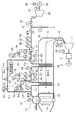
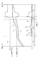
図1は、第1実施形態の発電プラントの構成を示す模式図である。図1の発電プラントは、排熱回収方式によるコンバインドサイクル火力発電プラントである。
(First embodiment)
図1の発電プラントは、ガスタービン1と、圧縮機2と、第1発電機3と、排ガス配管4と、排熱回収ボイラ5と、ドラム11と、下降管12と、蒸発器13と、第1過熱器14と、第1減温器15と、第2過熱器16と、第2減温器17と、第1減温器バルブ18と、第2減温器バルブ19と、制御装置20と、主蒸気配管21と、主蒸気弁22と、バイパス蒸気配管23と、バイパス蒸気弁24と、蒸気タービン25と、第2発電機26とを備えている。第1減温器15、第2過熱器16、第2減温器17、第1減温器バルブ18、第2減温器バルブ19、および制御装置20はそれぞれ、上流減温器、過熱器、下流減温器、第1弁、第2弁、およびプラント制御装置の例である。制御装置20は、図1の発電プラントの種々の動作を制御する。
The power plant in FIG. 1 includes a
本発電プラントはさらに、ドラム11と第1過熱器14との間の蒸気流路L1と、第1過熱器14と第1減温器15との間の蒸気流路L2と、第1減温器15と第2過熱器16との間の蒸気流路L3と、第2過熱器16と第2減温器17との間の蒸気流路L4とを備えている。
This power plant further comprises a steam channel L 1 between the
本発電プラントはさらに、排ガス配管4に設けられた温度計31および流量計32と、ドラム11に設けられた圧力計41と、蒸気流路L1に設けられた流量計42と、蒸気流路L2に設けられた温度計43と、蒸気流路L3に設けられた温度計44と、蒸気流路L4に設けられた温度計45と、主蒸気配管21に設けられた圧力計46、温度計47、および流量計48とを備えている。
This power plant further comprises a
本発電プラントはさらに、第1減温器バルブ18を介して第1減温器15に水を搬送する水流路に設けられた圧力計51、温度計52、および流量計53を備えている。本発電プラントはさらに、第2減温器バルブ19を介して第2減温器17に水を搬送する水流路に設けられた圧力計54、温度計55、および流量計56を備えている。本発電プラントはさらに、蒸気タービン25の蒸気タービンロータに設けられた回転数計測器57と、第2発電機26に設けられた電気出力計測器58とを備えている。
The power plant further includes a
図1の発電プラントにおいて、圧縮機2は、圧縮機2とガスタービン1との間に配置された燃焼器に圧縮空気を供給し、燃焼器は、圧縮空気を用いて燃料を燃焼させる。これにより、高温・高圧のガスが燃焼器内で発生し、ガスタービン1に供給される。ガスタービン1は、このガスにより回転駆動されることで、ガスタービンロータを回転させる。第1発電機3は、ガスタービンロータの回転を利用して発電を行う。ガスタービン1から排出された排ガスは、排ガス配管4を介して排熱回収ボイラ5に送られる。排熱回収ボイラ5に送られた排ガスは、第2過熱器16、第1過熱器14、蒸発器13の順でその熱が利用され、排熱回収ボイラ5から排出される。
In the power plant shown in FIG. 1, the
排ガスの状態は、制御装置20により制御される。例えば、制御装置20は、ガスタービン1や排熱回収ボイラ5の動作を制御することで、排熱回収ボイラ5の排ガス入口や排ガス出口における排ガス温度や排ガス圧力を設定値に制御することができる。
The state of the exhaust gas is controlled by the
一方、ドラム11内の水は、下降管12を介して排熱回収ボイラ5内の蒸発器13に送られ、蒸発器13内で排ガスの熱により加熱されることで、飽和水蒸気となる。この蒸気は、蒸気流路L1を介して排熱回収ボイラ5内の第1過熱器14に送られ、第1過熱器14で過熱された後、蒸気流路L2を介して第1減温器15に送られ、第1減温器15で冷却される。第1減温器15は、第1減温器バルブ18からの水により蒸気を冷却する。第1減温器15で冷却された蒸気は、蒸気流路L3を介して排熱回収ボイラ5内の第2過熱器16に送られ、第2過熱器16で再び過熱された後、蒸気流路L4を介して第2減温器17に送られ、第2減温器17で再び冷却される。第2減温器17は、第2減温器バルブ19からの水により蒸気を冷却する。
On the other hand, the water in the
蒸気の状態は、制御装置20により制御される。例えば、制御装置20は、第1減温器バルブ18の開度を調整して、第1減温器15でのスプレー水の流量を調整することで、第2過熱器16の出口蒸気温度を設定値に制御することができる。さらに、制御装置20は、第2減温器バルブ19の開度を調整して、第2減温器17でのスプレー水の流量を調整することで、第2減温器17の出口蒸気温度を設定値に制御することができる。
The state of the steam is controlled by the
具体的には、第1減温器15は、流入蒸気にスプレー水を混合することで、スプレー水のエンタルピと流入蒸気のエンタルピとを流量比率で加算した状態に流出蒸気を制御することができる。ただし、本実施形態の第1減温器15は、蒸気温度を所定温度(飽和蒸気温度に一定の余裕温度を加えた温度)未満に制御しない。また、第1減温器15におけるスプレー水の流量には上限があるため、蒸気温度を制御可能な範囲はこの上限に依存して決定される。これは、第2減温器17でも同様である。
Specifically, the
なお、本実施形態の第2過熱器16は、蒸気の流れに対し、排熱回収ボイラ5の最終段に位置する過熱器である。また、第1減温器15は、蒸気の流れに対し第2過熱器16の前段に位置しており、第2減温器17は、蒸気の流れに対し第2過熱器16の後段に位置している。
In addition, the
第2減温器17で冷却された蒸気(主蒸気)は、主蒸気配管21を介して蒸気タービン25に送られる。蒸気タービン25は、この蒸気により回転駆動されることで、蒸気タービンロータを回転させる。第2発電機26は、蒸気タービンロータの回転を利用して発電を行う。バイパス蒸気配管23は、蒸気タービン25の上流で主蒸気配管21から分岐している。主蒸気配管21には、主蒸気弁22が設けられている。バイパス蒸気配管23には、バイパス蒸気弁24が設けられている。
The steam (main steam) cooled by the
排熱回収ボイラ5から供給された蒸気の状態は、制御装置20により制御される。例えば、制御装置20は、主蒸気弁22やバイパス蒸気弁24の開度を調整することで、蒸気タービン25の蒸気入口における蒸気圧力や蒸気流量を設定値に制御することができる。
The state of the steam supplied from the exhaust
制御装置20は、蒸気タービン25の蒸気入口における蒸気流量を調整することで、蒸気タービン25の回転数を制御し、これにより第2発電機26の電気出力を設定値に制御する。第2発電機26の電気出力は、MW(メガワット)出力とも呼ばれる。なお、蒸気タービン25の回転数は、回転数計測器57により計測され、第2発電機26の電気出力は、電気出力計測器58により計測される。
The
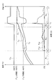
図2は、第1実施形態の発電プラントの動作を説明するためのグラフである。 FIG. 2 is a graph for explaining the operation of the power plant according to the first embodiment.
図2の横軸は、蒸気流路上の各地点とドラム11との距離を示す。図2の縦軸は、蒸気流路を流れる蒸気の温度を示す。符号T1は、蒸気流路L2を流れる蒸気の温度を示しており、温度計43により計測される。符号T2は、蒸気流路L3を流れる蒸気の温度を示しており、温度計44により計測される。符号T3は、蒸気流路L4を流れる蒸気の温度を示しており、温度計45により計測される。符号T4は、主蒸気配管(主蒸気流路)21を流れる蒸気の温度を示しており、温度計47により計測される。図2は、これらの温度計43、44、45、47による蒸気温度T1〜T4の計測値を示している。
The horizontal axis in FIG. 2 indicates the distance between each point on the steam flow path and the
以下、蒸気温度T1〜T4の計算方法を説明する。
Hereinafter, how to calculate the
第1減温器15の出口蒸気温度かつ第2過熱器16の入口蒸気温度である蒸気温度T2は、次の式(1)および(2)で与えられる。
T2=HPT(HT2,PT2) ・・・(1)
HT2={FS1×TPH(TS1,PS1)+FT1×TPH(T1,PT1)}
/(FT1+FS1) ・・・(2)
ただし、T1、PT1、FT1は、温度計43の地点を流れる蒸気の温度、圧力、流量を表す。FT1は、流量計42の地点を流れる蒸気の流量F1に等しい。T2、PT2、HT2は、温度計44の地点を流れる蒸気の温度、圧力、エンタルピを表す。PS1、TS1、FS1はそれぞれ、圧力計51、温度計52、流量計53の地点を流れるスプレー水の圧力、温度、流量を表す。HPTは、蒸気のエンタルピ(第1引数)と圧力(第2引数)から蒸気の温度を計算するための関数である。TPHは、蒸気の温度(第1引数)と圧力(第2引数)から蒸気のエンタルピを計算するための関数である。なお、圧力、温度、流量の単位は、MPa、℃、t/hである。
Steam temperature T 2 is an inlet steam temperature of the outlet steam temperature and the
T 2 = HPT (H T2 , P T2 ) (1)
H T2 = {F S1 × TPH (T S1 , P S1 ) + F T1 × TPH (T 1 , P T1 )}
/ (F T1 + F S1 ) (2)
However, T 1 , P T1 , and FT 1 represent the temperature, pressure, and flow rate of the steam flowing through the point of the
第2過熱器16の出口蒸気温度かつ第2減温器17の入口蒸気温度である蒸気温度T3は、次の式(3)および(4)で与えられる。
T3=Func(TG,FG,T2,FT2) ・・・(3)
FT2=FT1+FS1 ・・・(4)
ただし、T2、FT2は、温度計44の地点を流れる蒸気の温度と流量を表す。T3は、温度計45の地点を流れる蒸気の温度を表す。TG、FGはそれぞれ、温度計31、流量計32の地点を流れる排ガスの温度と流量を表す。Funcは、第2過熱器16の入口排ガス温度(第1引数)、入口排ガス流量(第2引数)、入口蒸気温度(第3引数)、および入口蒸気流量(第4引数)から第2過熱器16の出口蒸気温度を計算するための関数である。Funcは、後述するように、第2過熱器16内での排ガスと蒸気との熱交換量から出口蒸気温度を計算する。
The steam temperature T 3 that is the outlet steam temperature of the
T 3 = Func (T G , F G , T 2 , F T2 ) (3)
F T2 = F T1 + F S1 (4)
However, T 2 and FT 2 represent the temperature and flow rate of the steam flowing through the point of the
第2減温器17の出口蒸気温度である蒸気温度T4は、次の式(5)〜(7)で与えられる。
T4=HPT(HT4,PT4) ・・・(5)
HT4={FS2×TPH(TS2,PS2)+FT3×TPH(T3,PT3)}
/(FT3+FS2) ・・・(6)
FT3=FT2 ・・・(7)
ただし、T3、PT3、FT3は、温度計45の地点を流れる蒸気の温度、圧力、流量を表す。T4、PT4、HT4は、温度計47の地点を流れる蒸気の温度、圧力、エンタルピを表す。PT4は、圧力計46の地点を流れる蒸気の圧力P2に等しい。PS2、TS2、FS2はそれぞれ、圧力計54、温度計55、流量計56の地点を流れるスプレー水の圧力、温度、流量を表す。
Steam temperature T 4 is an outlet steam temperature of the
T 4 = HPT (H T4 , P T4 ) (5)
H T4 = {F S2 × TPH (T S2 , P S2 ) + F T3 × TPH (T 3 , P T3 )}
/ (F T3 + F S2 ) (6)
F T3 = F T2 (7)
However, T 3 , P T3 , and FT 3 represent the temperature, pressure, and flow rate of the steam flowing through the point of the
なお、式(1)〜(7)では、蒸気流路における圧力損失はほぼゼロであると仮定している。制御装置20は、温度計43〜45等から取得した計測値を式(1)〜(7)の右辺に代入することで、式(1)〜(7)の左辺の値を計算することができる。上記の圧力損失や温度計43〜45等の計測誤差が小さい場合、これらの式から蒸気温度T2〜T4の値を精度よく計算することができる。
In equations (1) to (7), it is assumed that the pressure loss in the steam channel is almost zero. The
次に、図3と図4を参照して、式(3)のFuncの計算方法を説明する。 Next, with reference to FIG. 3 and FIG. 4, a method of calculating the Func in the expression (3) will be described.
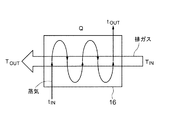
図3は、第1実施形態の第2過熱器16の構成を示す模式図である。図3は、排ガスと蒸気との熱交換の様子を示している。
FIG. 3 is a schematic diagram showing the configuration of the
符号Qは、第2過熱器16内での排ガスと蒸気との熱交換量[kW]を表す。符号tINは、第2過熱器16の入口蒸気温度を表し、蒸気温度T2に相当する。符号tOUTは、第2過熱器16の出口蒸気温度を表し、蒸気温度T3に相当する。符号TINは、第2過熱器16の入口排ガス温度を表し、排ガス温度TGに相当する。符号TOUTは、第2過熱器16の出口排ガス温度を表す。
The symbol Q represents the heat exchange amount [kW] between the exhaust gas and the steam in the
蒸気温度tIN、tOUTの間には、以下の式(8)の関係が成り立つ。また、排ガス温度TIN、TOUTの間には、以下の式(9)の関係が成り立つ。
tOUT=tIN+Q/c/f ・・・(8)
TOUT=TIN−Q/C/F ・・・(9)
ただし、cは蒸気の比熱[kW/℃/kg]を表し、fは蒸気の流量[kg/s]を表す。また、Cは排ガスの比熱[kW/℃/kg]を表し、Fは排ガスの流量[kg/s]を表す。例えば、熱交換量Qが定まると、式(8)を用いて出口蒸気温度tOUTの計測値から入口蒸気温度tINの設定値を計算することができる。
The relationship of the following formula (8) is established between the steam temperatures t IN and t OUT . Further, the exhaust gas temperature T IN, between T OUT is holds the relationship of the following equation (9).
t OUT = t IN + Q / c / f (8)
T OUT = T IN −Q / C / F (9)
Here, c represents the specific heat of steam [kW / ° C./kg], and f represents the flow rate of steam [kg / s]. C represents the specific heat of the exhaust gas [kW / ° C./kg], and F represents the flow rate [kg / s] of the exhaust gas. For example, when the heat exchange amount Q is determined, it is possible to calculate the set value of the inlet steam temperature t IN from the measured value of the outlet steam temperature t OUT using Equation (8).
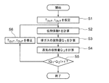
図4は、第1実施形態の熱交換量Qの計算方法を示すフローチャートである。 FIG. 4 is a flowchart illustrating a method for calculating the heat exchange amount Q according to the first embodiment.
まず、排ガス温度TOUTと蒸気温度tOUTを仮定する(ステップS1)。次に、第2過熱器16の伝熱係数h[kW/℃]を計算する(ステップS2)。本実施形態では、伝熱係数hは一定値であると想定する。
First, an exhaust gas temperature T OUT and a steam temperature t OUT are assumed (step S1). Next, the heat transfer coefficient h [kW / ° C.] of the
次に、排ガスの放熱量Q1[kW]と蒸気の収熱量Q2[kW]を計算する(ステップS3、S4)。放熱量Q1は、以下の式(10)で与えられる。収熱量Q2は、以下の式(11)で与えられる。
Q1=(TIN−TOUT)×C×F ・・・(10)
Q2=h{(TIN−tOUT)−(TOUT−tIN)}
/log{(TIN−tOUT)/(TOUT−tIN)} ・・・(11)
ここで、排ガス温度TOUTと蒸気温度tOUTの仮定が正しければ、エネルギー保存則より放熱量Q1と収熱量Q2は一致する。そこで、放熱量Q1と収熱量Q2との差の絶対値を閾値εと比較する(ステップS5)。
Next, a heat release amount Q 1 [kW] of exhaust gas and a heat recovery amount Q 2 [kW] of steam are calculated (steps S3 and S4). Heat radiation amount Q 1 is given by the following equation (10). Heat absorption Q 2 is given by the following equation (11).
Q 1 = (T IN −T OUT ) × C × F (10)
Q 2 = h {(T IN −t OUT ) − (T OUT −t IN )}
/ Log {(T IN -t OUT ) / (T OUT -t IN )} (11)
Here, if the assumptions of the exhaust gas temperature T OUT and the steam temperature t OUT are correct, the heat dissipation amount Q 1 and the heat recovery amount Q 2 coincide with each other from the energy conservation law. Therefore, comparing the absolute value of the difference between the heat radiation amount Q 1, heat absorption Q 2 with the threshold value epsilon (step S5).
絶対値|Q1−Q2|が閾値εより大きい場合には、排ガス温度TOUTと蒸気温度tOUTを修正する(ステップS6)。本方法ではその後、修正された排ガス温度TOUTと蒸気温度tOUTを用いてステップS2〜S5を繰り返す。 If the absolute value | Q 1 −Q 2 | is larger than the threshold value ε, the exhaust gas temperature T OUT and the steam temperature t OUT are corrected (step S6). Then the method repeats step S2~S5 using the modified exhaust gas temperature T OUT and the steam temperature t OUT.
一方、絶対値|Q1−Q2|が閾値εより小さい場合には、ステップS3で計算された放熱量Q1(またはステップS4で計算された収熱量Q2)を、熱交換量Qに決定する。このようにして、第2過熱器16の熱交換量Qを計算することができ、これにより関数Funcを計算することができる。この際、制御装置20は、排ガス温度TINを変更して本方法を繰り返し実行することで、蒸気温度tOUTが目標温度となる排ガス温度TINの目標温度を探索することができる。
On the other hand, when the absolute value | Q 1 −Q 2 | is smaller than the threshold value ε, the heat release amount Q 1 calculated in step S3 (or the heat recovery amount Q 2 calculated in step S4) is used as the heat exchange amount Q. decide. In this way, the heat exchange amount Q of the
(1)第1実施形態の制御装置20
図5は、第1実施形態の制御装置20の構成を示す模式図である。
(1)
FIG. 5 is a schematic diagram illustrating a configuration of the
制御装置20は、第1設定部61と、第2設定部62と、加算器63と、上限値設定部64と、余裕値設定部65と、減算器66と、選択部67と、第1減温器制御部68と、第2減温器制御部69とを備えている。第1および第2減温器制御部68、69はそれぞれ、第1および第2制御部の例である。図5は、制御装置20の構成要素のうち、蒸気温度の制御に関連する構成要素を示している。
The
制御装置20は、単一のハードウェアに搭載されたコンピュータや電気回路により実現されてもよいし、複数のハードウェアに搭載されたコンピュータや電気回路により実現されてもよい。後者の場合、制御装置20は、ハードウェア間で相互に通信を行いながら本発電プラントを制御する。本実施形態の制御装置20は、単一のハードウェアにより実現されていると想定する。ただし、以下の説明は、複数のハードウェアにより実現された制御装置20にも適用可能である。
The
第1設定部61は、温度計45の地点での蒸気温度T3を調整するための設定値として、T4負偏差許容値を保持している。温度計45の地点は、過熱器と下流減温器との間の第1地点の例である。蒸気温度T3は、第1温度の例である。T4負偏差許容値は、第1設定値の例である。
The
T4負偏差許容値は、蒸気温度T3を、蒸気温度T4の設定値と関連して調整するための設定値である。本実施形態のT4負偏差許容値は、10℃であり、時間に応じて変化しない定数である。 The T 4 negative deviation allowable value is a set value for adjusting the steam temperature T 3 in relation to the set value of the steam temperature T 4 . The T 4 negative deviation allowable value of this embodiment is 10 ° C., and is a constant that does not change with time.
第2設定部62は、温度計47の地点での蒸気温度T4を調整するための設定値として、T4設定値を保持している。温度計47の地点は、下流減温器の下流の第2地点の例である。蒸気温度T4は、第2温度の例である。T4設定値は、第2設定値の例である。
The
T4設定値は、蒸気温度T4を調整するための設定値である。図6に示すように、本実施形態のT4設定値は、時間に応じて変化する。 The T 4 set value is a set value for adjusting the steam temperature T 4 . As shown in FIG. 6, the T 4 set value of the present embodiment changes according to time.
図6は、第1実施形態のT4設定値の例を示すグラフである。 FIG. 6 is a graph illustrating an example of the T 4 set value according to the first embodiment.
第2設定部62は、図6に示すようなT4設定値の時系列値を保持している。よって、第2設定部62から出力されるT4設定値は、時間の経過と共に変化していく。図6は、本発電プラントの起動時におけるT4設定値の例を示している。
The
以下、図5を再び参照し、制御装置20の構成を説明する。
Hereinafter, the configuration of the
加算器63は、第1設定部61から出力されたT4負偏差許容値と、第2設定部62から出力されたT4設定値とを取得する。そして、加算器63は、T4設定値にT4負偏差許容値を加算して、T3設定値を出力する(T3設定値=T4設定値+T4負偏差許容値)。
The
上限値設定部64は、本発電プラントの蒸気温度の上限値、具体的には、蒸気温度T4の上限値として、550℃を保持している。余裕値設定部65は、この上限値の余裕値として、3℃を保持している。これは、蒸気温度T4が上限値を超えることを確実に防ぐために、蒸気温度T4を550℃(上限値)を基準として制限する代わりに、蒸気温度T4を547℃(上限値−余裕値)を基準として制限するためである。
Upper limit
減算器66は、上限値設定部64から出力された上限値と、余裕値設定部65から出力された余裕値とを取得する。そして、減算器66は、上限値から余裕値を減算して、蒸気温度T4の修正上限値を出力する(修正上限値=上限値−余裕値)。
The
選択部67は、加算器63から出力されたT3設定値と、減算器66から出力された修正上限値とを取得する。そして、選択部67は、T3設定値と修正上限値との低い方の値を出力する。これは、蒸気温度T3が上限値を超えることを防ぐことで、蒸気温度T4が上限値を超えることを防ぐためである。
The
なお、選択部67は、T3設定値と修正上限値(547℃)の低い方を出力する代わりに、T3設定値と上限値(550℃)の低い方を出力してもよい。すなわち、本実施形態では、余裕値(3℃)を採用しても採用しなくてもよい。前者の修正上限値と後者の上限値は、いずれも制限値の例である。後者の場合には、余裕値設定部65と減算部66は不要である。一方、前者の場合には、上限値設定部64、余裕値設定部65、および減算器66は、修正上限値を保持する修正上限値保持部に置き換えてもよい。
The
第1減温器制御部68は、蒸気温度T3がT3設定値と修正上限値の低い方に調整されるように、第1減温器15を制御する。具体的には、第1減温器制御部68は、これらの低い方に基づいて、第1減温器バルブ18の開度指示値ZS1を算出して出力する。これにより、第1減温器バルブ18の開度が開度指示値ZS1に調整され、蒸気温度T3がT3設定値と修正上限値の低い方に近づいていく。
The first temperature
第1減温器制御部68は例えば、PID(Proportional-Integral-Derivative)制御により第1減温器15を制御する。具体的には、第1減温器制御部68は、温度計45から蒸気温度T3の計測値を取得し、T3設定値と修正上限値の低い方とこの計測値との偏差を算出し、この偏差をゼロに近づけるように開度指示値ZS1を設定する。
The first temperature
第2減温器制御部69は、蒸気温度T4がT4設定値に調整されるように、第2減温器17を制御する。具体的には、第2減温器制御部69は、T4設定値に基づいて、第2減温器バルブ19の開度指示値ZS2を算出して出力する。これにより、第2減温器バルブ19の開度が開度指示値ZS2に調整され、蒸気温度T4がT4設定値に近づいていく。
The second temperature
第2減温器制御部69は例えば、PID制御により第2減温器17を制御する。具体的には、第1減温器制御部69は、温度計47から蒸気温度T4の計測値を取得し、T4設定値とこの計測値との偏差を算出し、この偏差をゼロに近づけるように開度指示値ZS2を設定する。
For example, the second temperature
なお、本実施形態の制御装置20は、定周期で動作する。制御装置20の動作周期は、例えば1秒である。この場合、開度指示値ZS1、ZS2は、1秒ごとに更新される。
Note that the
ここで、第1設定部61のT4負偏差許容値について詳細に説明する。
Here, the T 4 negative deviation allowable value of the
温度計45は、第2減温器17の入口蒸気温度である蒸気温度T3を計測し、温度計47は、第2減温器17の出口蒸気温度である蒸気温度T4を計測する。蒸気温度T3がT4設定値よりも高い場合には、第2減温器17は、取り込んだ蒸気の温度をT3から冷却により低下させることで、蒸気温度T4をT4設定値に調整することができる。一方、蒸気温度T3がT4設定値よりも低い場合には、第2減温器17は、蒸気温度T4をT4設定値に調整することができない。理由は、第2減温器17は、取り込んだ蒸気の温度をT3から過熱により上昇させることはできないからである。
The
この問題は、蒸気温度T3をT4設定値よりも高く維持することで回避可能である。そのため、本実施形態では、T3設定値をT4設定値よりも高く設定するために、T3設定値に対するT4設定値の偏差を負に設定している(T4設定値−T3設定値<0)。よって、本実施形態のT3設定値は、T4設定値とT4負偏差許容値との和に設定されている。(T3設定値=T4設定値+T4負偏差許容値)。T4負偏差許容値は、正の値であり、例えば10℃である。これにより、T3設定値に対するT4設定値の偏差を定常的に負に設定することが可能となる。 This problem can be avoided by maintaining the steam temperature T 3 higher than the T 4 set value. Therefore, in this embodiment, T 3 set value to be set higher than T 4 set value is set to a negative deviation of T 4 setting for T 3 set value (T 4 set value -T 3 Setting value <0). Therefore, the T 3 set value of this embodiment is set to the sum of the T 4 set value and the T 4 negative deviation allowable value. (T 3 set value = T 4 set value + T 4 negative deviation tolerance). T 4 negative deviation allowable value is a positive value, for example, 10 ° C.. Thus, it is possible to set the deviation of T 4 setting for T 3 set value to a negative constantly.
この場合、蒸気温度T3は蒸気温度T4よりも10℃高く調整される。そのため、蒸気温度T4が上限値に到達するより前に、蒸気温度T3が上限値に到達してしまう。そこで、本実施形態では、蒸気温度T3をT3設定値と上限値(詳細には、修正上限値)とに基づいて調整する。これにより、本発電プラントの蒸気温度が上限値に到達することを防ぐことが可能となる。 In this case, the steam temperature T 3 is adjusted to be higher 10 ° C. than the vapor temperature T 4. Therefore, prior to the steam temperature T 4 reaches the upper limit value, the steam temperature T 3 would reach the upper limit. Therefore, in this embodiment, 3 setpoint steam temperature T 3 T and the upper limit value (specifically, corrected upper limit value) is adjusted based on the. Thereby, it becomes possible to prevent the steam temperature of the power plant from reaching the upper limit value.
(2)第1実施形態および比較例の発電プラントの動作
図7は、第1実施形態の比較例の発電プラントの動作例を示すグラフである。比較例の発電プラントは、本実施形態の発電プラントと同様の構成を有しているが、比較例のT4負偏差許容値は、0℃に設定されている。
(2) Operation of Power Plant of First Embodiment and Comparative Example FIG. 7 is a graph showing an operation example of the power plant of the comparative example of the first embodiment. The power plant of the comparative example has the same configuration as the power plant of the present embodiment, but the T 4 negative deviation allowable value of the comparative example is set to 0 ° C.
図7は、時間t1よりも前の期間R1と、時間t1〜t2の期間R2と、時間t2〜t3の期間R3と、時間t3よりも後の期間R4における発電プラントの動作例を示している。
Figure 7 is a period R 1 earlier than time t 1, the
期間R1では、流量計53の地点でのスプレー流量FS1と、流量計56の地点でのスプレー流量FS2が、いずれも0に設定されている。よって、蒸気温度T2は、蒸気温度T1と同じ値になり、時間と共に上昇していく。同様に、蒸気温度T4は、蒸気温度T3と同じ値になり、時間と共に上昇していく。
In the period R 1 , the spray flow rate F S1 at the point of the
期間R2では、スプレー流量FS1は一定値に設定されている。その結果、蒸気温度T2は、緩やかに低下または上昇している。一方、第1減温器15での蒸気温度の低下速度よりも第2過熱器16での蒸気温度の上昇速度の方が速いため、蒸気温度T3は時間と共に上昇していく。また、T4設定値は期間R2の前半にて一定値(400℃)に維持されるため(図6参照)、スプレー流量FS2は、蒸気温度T4が400℃に維持されるように調整される。その後、T4設定値は期間R2の後半にて400℃から緩やかに上昇するため(図6参照)、スプレー流量FS2は時間と共に低下していき、蒸気温度T4は時間と共に上昇していく。
In the period R 2, spray flow F S1 is set to a constant value. As a result, the steam temperature T 2 is slowly decrease or increase. On the other hand, than the decrease rate of the steam temperature at the
期間R2の後半に蒸気温度T4が蒸気温度T3よりも急峻に上昇することで、期間R3では、蒸気温度T4が蒸気温度T3に到達している(矢印A1)。これは、比較例のT4負偏差許容値が0℃に設定され、T3設定値がT4設定値と等しいことに起因する。この場合、蒸気温度T3と蒸気温度T4は共にT4設定値に近づくように調整されるため、蒸気温度T3がT4設定値よりも低くなる場合がある。この場合、第2減温器17は、取り込んだ蒸気の温度を上昇させることができないため、蒸気温度T4をT4設定値に調整することができない。よって、蒸気温度T4は蒸気温度T3を超えることができない。(矢印A1)。その結果、期間R3では蒸気温度T4とT4設定値との間に乖離が発生する。
Steam temperature T 4 in the second half of the period R 2 that is sharply higher than the steam temperature T 3, in the period R 3, steam temperature T 4 has reached the steam temperature T 3 (arrow A 1). This is because the T 4 negative deviation allowable value of the comparative example is set to 0 ° C., and the T 3 set value is equal to the T 4 set value. In this case, since it is adjusted so that the steam temperature T 3 and the steam temperature T 4 approaches both T 4 set value, there is a case where the steam temperature T 3 lower than T 4 setting. In this case, the
期間R4では、蒸気温度T3が修正上限値(547℃)に到達している。その結果、蒸気温度T3は547℃に維持され、蒸気温度T4も547℃に維持されている。スプレー流量FS1は、蒸気温度T3を547℃に維持するように調整される。一方、蒸気温度T3と蒸気温度T4は共に547℃に調整されるため、スプレー流量FS2はおおむね0に維持される。スプレー流量FS2は、蒸気温度T4が547℃よりも高くなった場合だけ0から増加する。 In the period R 4 , the steam temperature T 3 has reached the corrected upper limit value (547 ° C.). As a result, the steam temperature T 3 is maintained at 547 ° C., and the steam temperature T 4 is also maintained at 547 ° C. The spray flow rate F S1 is adjusted to maintain the vapor temperature T 3 at 547 ° C. Meanwhile, since the steam temperature T 3 and the steam temperature T 4 is adjusted to both 547 ° C., spray flow F S2 is maintained substantially zero. The spray flow rate F S2 increases from 0 only when the vapor temperature T 4 becomes higher than 547 ° C.
図8は、第1実施形態の発電プラントの動作例を示すグラフである。比較例のT4負偏差許容値は0℃に設定されているのに対し、本実施形態のT4負偏差許容値は10℃に設定されている。 FIG. 8 is a graph illustrating an operation example of the power plant according to the first embodiment. The T 4 negative deviation allowable value of the comparative example is set to 0 ° C., whereas the T 4 negative deviation allowable value of the present embodiment is set to 10 ° C.
期間R1では、スプレー流量FS1、FS2が0に設定されている。よって、蒸気温度T2は、蒸気温度T1と同じ値になり、時間と共に上昇していく。同様に、蒸気温度T4は、蒸気温度T3と同じ値になり、時間と共に上昇していく。 In the period R 1 , the spray flow rates F S1 and F S2 are set to zero. Accordingly, the steam temperature T 2 is the same value as the steam temperature T 1, rises with time. Similarly, steam temperature T 4 is the same value as the steam temperature T 3, rises with time.
期間R2では、スプレー流量FS1は当初、一定値に設定されている(矢印B1)。その結果、蒸気温度T2は、緩やかに低下または上昇している。一方、第1減温器15での蒸気温度の低下速度よりも第2過熱器16での蒸気温度の上昇速度の方が速いため、蒸気温度T3は時間と共に上昇していく。また、T4設定値は期間R2の前半にて一定値(400℃)に維持されるため(図6参照)、スプレー流量FS2は、蒸気温度T4が400℃に維持されるように調整される。その後、T4設定値は期間R2の後半にて400℃から緩やかに上昇するため(図6参照)、蒸気温度T4は時間と共に上昇していく。
In the period R 2 , the spray flow rate F S1 is initially set to a constant value (arrow B 1 ). As a result, the steam temperature T 2 is slowly decrease or increase. On the other hand, than the decrease rate of the steam temperature at the
ただし、本実施形態のT4負偏差許容値は10℃に設定されており、T3設定値がT4設定値よりも高い。その結果、期間R2の後半に蒸気温度T4が上昇しても、期間R3に蒸気温度T4が蒸気温度T3に到達していない(矢印A2)。よって、本実施形態の第2減温器17は、期間R3にて蒸気温度T4をT4設定値に調整することができ、蒸気温度T4とT4設定値との間に乖離が発生することを抑制することができる。期間R2、R3において、スプレー流量FS1は、蒸気温度T3がT3設定値(=T4設定値+T4負偏差許容値)に近づくように調整される(矢印B2、B3)。同様に、スプレー流量FS2は、蒸気温度T4がT4設定値に近づくように調整される。
However, the T 4 negative deviation allowable value of this embodiment is set to 10 ° C., and the T 3 set value is higher than the T 4 set value. As a result, even if increased steam temperature T 4 in the second half of the period R 2, steam temperature T 4 does not reach the steam temperature T 3 in the period R 3 (arrow A 2). Thus, the
本実施形態のスプレー流量FS2は、時間t1〜t3の間に0に到達していないことに留意されたい。これは、時間t1〜t3の間、第2減温器17が蒸気温度T4をT4設定値に調整し続けていることを意味する。
It should be noted that the spray flow rate F S2 of this embodiment has not reached 0 between times t 1 and t 3 . This, during the
期間R4では、期間R3にて蒸気温度T3が547℃に到達した後、蒸気温度T4が547℃に到達している。その結果、蒸気温度T3は547℃に維持され、蒸気温度T4も547℃に維持されている。スプレー流量FS1は、蒸気温度T3を547℃に維持するように調整される。一方、蒸気温度T3と蒸気温度T4は共に547℃に調整されるため、スプレー流量FS2はおおむね0に維持される。スプレー流量FS2は、蒸気温度T4が547℃よりも高くなった場合だけ0から増加する。 In the period R 4, after the steam temperature T 3 during the period R 3 has reached 547 ° C., steam temperature T 4 has reached 547 ° C.. As a result, the steam temperature T 3 is maintained at 547 ° C., and the steam temperature T 4 is also maintained at 547 ° C. The spray flow rate F S1 is adjusted to maintain the vapor temperature T 3 at 547 ° C. Meanwhile, since the steam temperature T 3 and the steam temperature T 4 is adjusted to both 547 ° C., spray flow F S2 is maintained substantially zero. The spray flow rate F S2 increases from 0 only when the vapor temperature T 4 becomes higher than 547 ° C.
(3)第1実施形態の変形例
図9は、第1実施形態の変形例の発電プラントの構成を示す模式図である。
(3) Modified Example of First Embodiment FIG. 9 is a schematic diagram illustrating a configuration of a power plant according to a modified example of the first embodiment.
本変形例の蒸気タービン25は、高圧タービン25aと低圧タービン25bにより構成されている。高圧タービン25aは、蒸気の流れに対し、第2減温器17の下流に設けられている。低圧タービン25bは、蒸気の流れに対し、高圧タービン25aの下流に設けられている。高圧、低圧タービン25a、25bはそれぞれ、第1、第2蒸気タービンの例である。
The
本変形例の発電プラントは、図1に示す構成要素に加え、第3過熱器101と、第3減温器102と、第4過熱器103と、第4減温器104と、第3減温器バルブ105と、第4減温器バルブ106とを備えている。第3減温器102、第4過熱器103、第4減温器104、第3減温器バルブ105、および第4減温器バルブ106はそれぞれ、上流減温器、過熱器、下流減温器、第1弁、および第2弁の例である。
In addition to the components shown in FIG. 1, the power plant according to the present modification includes a
第3および第4過熱器101、103は、第1および第2過熱器14、16と同様に、排熱回収ボイラ5内に設けられている。第3および第4過熱器101、103は、高圧タービン25aから低圧タービン25bに供給される蒸気を排ガスの熱により再熱する再熱器である。
The third and
本発電プラントは更に、高圧タービン25aと第3過熱器101との間の蒸気流路LAと、第3過熱器101と第3減温器102との間の蒸気流路LBと、第3減温器102と第4過熱器103との間の蒸気流路LCと、第4過熱器103と第4減温器104との間の蒸気流路LDと、第4減温器104と低圧タービン25bとの間の蒸気流路LEとを備えている。
This power plant further comprises a steam channel L A between the
本発電プラントは更に、蒸気流路LAに設けられた流量計111と、蒸気流路LBに設けられた温度計112と、蒸気流路LCに設けられた温度計113と、蒸気流路LDに設けられた温度計114と、蒸気流路LEに設けられた圧力計115、温度計116、および流量計117とを備えている。
This power plant further includes a
本発電プラントは更に、第3減温器バルブ105を介して第3減温器102に水を搬送する水流路に設けられた圧力計121、温度計122、および流量計123と、第4減温器バルブ106を介して第4減温器104に水を搬送する水流路に設けられた圧力計124、温度計125、および流量計126とを備えている。
The power plant further includes a
第2減温器17から排出された蒸気は、主蒸気配管21を介して高圧タービン25aに送られる。高圧タービン25aは、この蒸気により回転駆動されることで、蒸気タービンロータを回転させる。また、高圧タービン25aから排出された蒸気は、蒸気配管LA〜LEを介して低圧タービン25bに送られる。低圧タービン25bは、この蒸気により回転駆動されることで、蒸気タービンロータを高圧タービン25aと共に回転させる。第2発電機26は、蒸気タービンロータの回転を利用して発電を行う。
The steam discharged from the
バイパス蒸気配管23は、蒸気タービン25の上流で主蒸気配管21から分岐し、蒸気流路LAに合流している。よって、主蒸気弁22とバイパス蒸気弁24とが開いている場合、低圧タービン25bは、高圧タービン25aを通過した蒸気と、高圧タービン25aをバイパスした蒸気により回転駆動される。
Pass
蒸気流路LAの蒸気は、排熱回収ボイラ5内の第3過熱器101に送られ、第1過熱器101で過熱された後、蒸気流路LBを介して第3減温器102に送られ、第3減温器102で冷却される。第3減温器102は、第3減温器バルブ105からの水により蒸気を冷却する。第3減温器102で冷却された蒸気は、蒸気流路LCを介して排熱回収ボイラ5内の第4過熱器103に送られ、第4過熱器103で再び過熱された後、蒸気流路LDを介して第4減温器104に送られ、第4減温器104で再び冷却される。第4減温器104は、第4減温器バルブ106からの水により蒸気を冷却する。第4減温器104で冷却された蒸気は、蒸気流路LEを介して低圧タービン25bに送られる。
Vapor steam channel L A is fed to the
蒸気流路LA〜LEを流れる蒸気の状態は、制御装置20により制御される。例えば、制御装置20は、第3減温器バルブ105の開度を調整して、第3減温器102でのスプレー水の流量を調整することで、第4過熱器103の出口蒸気温度を設定値に制御することができる。さらに、制御装置20は、第4減温器バルブ106の開度を調整して、第4減温器104でのスプレー水の流量を調整することで、第4減温器104の出口蒸気温度を設定値に制御することができる。これは、第1および第2減温器15、17の制御と同様である。
State of the steam flowing through the steam channel L A ~L E is controlled by the
なお、本実施形態の第4過熱器103は、蒸気の流れに対し、排熱回収ボイラ5の最終段に位置する過熱器である。また、第3減温器102は、蒸気の流れに対し第4過熱器103の前段に位置しており、第4減温器104は、蒸気の流れに対し第4過熱器103の後段に位置している。
In addition, the
図2〜図8の説明は、本変形例の第1、第2過熱器14、16および第1、第2減温器15、17にも適用可能である。また、図2〜図8の説明は、第1、第2過熱器14、16および第1、第2減温器15、17を第3、第4過熱器101、103および第3、第4減温器102、104に置き換えることで、本変形例の第3、第4過熱器101、103および第3、第4減温器102、104にも適用可能である。
The description of FIGS. 2 to 8 is also applicable to the first and second superheaters 14 and 16 and the first and
この場合、図2〜図8の説明において、符号42〜48で示す流量計、温度計、圧力計は、符号111〜117で示す流量計、温度計、圧力計に置き換えられる。また、符号51〜56で示す流量計、温度計、圧力計は、符号121〜126で示す流量計、温度計、圧力計に置き換えられる。また、図5のT4負偏差許容値、T4設定値、第1減温器バルブ18の開度指示値ZS1、第2減温器バルブ19の開度指示値ZS2は、T8負偏差許容値、T8設定値、第3減温器バルブ105の開度指示値ZS3、第4減温器バルブ106の開度指示値ZS4に置き換えられる。この場合、蒸気温度T7や蒸気温度T8を、蒸気温度T3や蒸気温度T4と同様に適切に制御することが可能となる。
In this case, in the description of FIGS. 2 to 8, the flow meters, thermometers, and pressure gauges indicated by
以上のように、本実施形態の発電プラントは、第2過熱器16の前段および後段に第1および第2減温器15、17を備え、これら2つの減温器により蒸気温度T4をT4設定値に制御する。よって、本実施形態によれば、1つの減温器により蒸気温度T4を制御する場合に比べて、蒸気温度T4を高精度に制御することや、発電プラントを短時間で起動することが可能となる。
As described above, the power generation plant of this embodiment, the upstream and downstream of the
また、本実施形態の発電プラントは、蒸気温度T3がT4設定値よりもT4負偏差許容値だけ高く調整されるように、第1減温器15を制御し、蒸気温度T4がT4設定値に調整されるように、第2減温器17を制御する。よって、本実施形態によれば、蒸気温度T3がT4設定値よりも低くなって第2減温器17が蒸気温度T4を調整不能になる事態を抑制することが可能となる。よって、本実施形態によれば、蒸気温度T4を安定的に制御することが可能となる。
Further, the power generation plant of this embodiment, as the steam temperature T 3 is higher adjusted by T 4 negative deviation tolerance than T 4 set value, and controls the
(第2実施形態)
図10は、第2実施形態の発電プラントの構成を示す模式図である。
(Second Embodiment)
FIG. 10 is a schematic diagram illustrating a configuration of a power plant according to the second embodiment.
図10の発電プラントは、図1に示す構成要素に加え、バイパス流路L5〜L7を備えている。蒸気流路L1〜L4は、ドラム11からの蒸気を第1、第2過熱器14、16および第1、第2減温器15、17を介して搬送するのに対し、バイパス流路L5〜L7は、ドラム11からの蒸気を蒸気流路L1〜L4の少なくとも一部をバイパスして搬送する。
The power plant shown in FIG. 10 includes bypass flow paths L 5 to L 7 in addition to the components shown in FIG. The steam flow paths L 1 to L 4 convey the steam from the
具体的には、バイパス流路L5は、流量計42の上流の地点において、蒸気流路L1から分岐している。バイパス流路L6、L7は、バイパス流路L5から分岐している。バイパス流路L6は、バイパス流路L5からの蒸気を、蒸気流路L2との合流地点C1に供給する。バイパス流路L7は、バイパス流路L5からの蒸気を、蒸気流路L4との合流地点C2に供給する。
Specifically, the bypass flow path L 5 is branched from the steam flow path L 1 at a point upstream of the
本発電プラントはさらに、蒸気流路L2に設けられた温度計43’と、蒸気流路L4に設けられた温度計45’とを備えている。温度計43が、合流地点C1の上流に位置するのに対し、温度計43’は、合流地点C1の下流に位置している。同様に、温度計45が、合流地点C2の上流に位置するのに対し、温度計45’は、合流地点C2の下流に位置している。
This power plant further comprises 'and,
本発電プラントはさらに、バイパス流路L6に設けられた第1バイパス弁71および第1バイパス流量計73と、バイパス流路L7に設けられた第2バイパス弁72および第2バイパス流量計74とを備えている。
The power plant further includes a
本発電プラントは、蒸気流路L2からの蒸気を第1減温器15により冷却することができ、蒸気流路L4からの蒸気を第2減温器17により冷却することができる。また、本発電プラントは、蒸気流路L2の蒸気をバイパス流路L6からの蒸気により冷却することができ、蒸気流路L4の蒸気をバイパス流路L7からの蒸気により冷却することができる。
In the present power plant, steam from the steam flow path L 2 can be cooled by the
この際、合流地点C1の下流の蒸気温度は、合流地点C1の上流の蒸気と、バイパス流路L6の蒸気との流量比率により制御可能である。合流地点C1の下流の蒸気温度の上限は、合流地点C1の上流の蒸気温度となり、合流地点C1の下流の蒸気温度の下限は、バイパス流路L6の蒸気温度となる。これは、合流地点C2でも同様である。 In this case, downstream of the steam temperature of the junction C 1 can be controlled and upstream of the steam junction C 1, the flow rate ratio of the vapor of the bypass passage L 6. Downstream of the upper limit of the steam temperature of the junction C 1 becomes an upstream steam temperature of junction C 1, downstream of the lower limit of the steam temperature of the junction C 1 is a steam temperature of the bypass passage L 6. This is the same even in the confluence C 2.
図11は、第2実施形態の発電プラントの動作を説明するためのグラフである。 FIG. 11 is a graph for explaining the operation of the power plant according to the second embodiment.
図11の横軸は、蒸気流路上の各地点とドラム11との距離を示す。図11の縦軸は、蒸気流路を流れる蒸気の温度を示す。符号T1、T1’は、蒸気流路L2を流れる蒸気の温度を示しており、温度計43、43’により計測される。符号ΔT1は、T1とT1’との温度差を示す(ΔT1=T1−T1’)。符号T2は、蒸気流路L3を流れる蒸気の温度を示しており、温度計44により計測される。符号T3、T3’は、蒸気流路L4を流れる蒸気の温度を示しており、温度計45、45’により計測される。符号ΔT3は、T3とT3’との温度差を示す(ΔT3=T3−T3’)。符号T4は、主蒸気配管21を流れる蒸気の温度を示しており、温度計47により計測される。図11は、これらの温度計43、43’、44、45、45’、47による蒸気温度T1〜T4の計測値を示している。
The horizontal axis in FIG. 11 indicates the distance between each point on the steam flow path and the
以下、蒸気温度T1〜T4の計算方法を説明する。
Hereinafter, how to calculate the
合流地点C1と第1減温器15との間の地点での蒸気温度T1’は、次の式(12)で与えられる。
T1’=(TFB1+T1FT1)/(FB1+FT1) ・・・(12)
ただし、Tは、バイパス流路L5〜L7を流れる蒸気の温度を表す。ここでのTは、圧力計41の地点の蒸気の圧力(ドラム圧力)が飽和蒸気圧力であるとして計算された飽和蒸気温度である。T1、FT1は、温度計43の地点を流れる蒸気の温度、流量を表す。FT1は、流量計42の地点を流れる蒸気の流量F1に等しい。T1’は、温度計43’の地点を流れる蒸気の温度を表す。FB1は、第1バイパス流量計73の地点を流れる蒸気の流量を表す。
The steam temperature T 1 ′ at the point between the merging point C 1 and the
T 1 ′ = (TF B1 + T 1 F T1 ) / (F B1 + F T1 ) (12)
However, T is, representative of the temperature of steam flowing through the
第1減温器15の出口蒸気温度かつ第2過熱器16の入口蒸気温度である蒸気温度T2は、式(1)および(2)と同様に、次の式(13)〜(15)で与えられる。
T2=HPT(HT2,PT2) ・・・(13)
HT2={FS1×TPH(TS1,PS1)+FT1’×TPH(T1’,PT1’)}
/(FT1’+FS1) ・・・(14)
FT1’=FT1+FB1 ・・・(15)
ただし、T1’、PT1’、FT1’は、温度計43’の地点を流れる蒸気の温度、圧力、流量を表す。T2、PT2、HT2は、温度計44の地点を流れる蒸気の温度、圧力、エンタルピを表す。PS1、TS1、FS1はそれぞれ、圧力計51、温度計52、流量計53の地点を流れるスプレー水の圧力、温度、流量を表す。
Steam temperature T 2 is an inlet steam temperature of the outlet steam temperature and the
T 2 = HPT (H T2 , P T2 ) (13)
H T2 = {F S1 × TPH (T S1 , P S1 ) + F T1 ′ × TPH (T 1 ′, P T1 ′)}
/ (F T1 '+ F S1 ) (14)
F T1 ′ = F T1 + F B1 (15)
However, T 1 ′, P T1 ′, and F T1 ′ represent the temperature, pressure, and flow rate of the steam flowing through the point of the
第2過熱器16の出口蒸気温度かつ第2減温器17の入口蒸気温度である蒸気温度T3は、式(3)および(4)と同様に、次の式(16)および(17)で与えられる。
T3=Func(TG,FG,T2,FT2) ・・・(16)
FT2=FT1’+FS1 ・・・(17)
ただし、T2、FT2は、温度計44の地点を流れる蒸気の温度と流量を表す。T3は、温度計45の地点を流れる蒸気の温度を表す。TG、FGはそれぞれ、温度計31、流量計32の地点を流れる排ガスの温度と流量を表す。
Steam temperature T 3 is the inlet steam temperature of the outlet steam temperature and the
T 3 = Func (T G , F G , T 2 , F T2 ) (16)
F T2 = F T1 '+ F S1 (17)
However, T 2 and FT 2 represent the temperature and flow rate of the steam flowing through the point of the
合流地点C2と第2減温器17との間の地点での蒸気温度T3’は、次の式(18)および(19)で与えられる。
T3’=(TFB2+T3FT3)/(FB2+FT3) ・・・(18)
FT3=FT2 ・・・(19)
ただし、T3、FT3は、温度計45の地点を流れる蒸気の温度、流量を表す。T3’は、温度計45’の地点を流れる蒸気の温度を表す。FB2は、第2バイパス流量計74の地点を流れる蒸気の流量を表す。
The steam temperature T 3 ′ at a point between the merging point C 2 and the
T 3 '= (TF B 2 + T 3 F T3 ) / (F B2 + F T3 ) (18)
F T3 = F T2 (19)
However, T 3 and F T3 represent the temperature and flow rate of the steam flowing through the point of the
第2減温器17の出口蒸気温度である蒸気温度T4は、式(5)〜(7)と同様に、次の式(20)〜(22)で与えられる。
T4=HPT(HT4,PT4) ・・・(20)
HT4={FS2×TPH(TS2,PS2)+FT3’×TPH(T3’,PT3’)}
/(FT3’+FS2) ・・・(21)
FT3’=FT3+FB2 ・・・(22)
ただし、T3’、PT3’、FT3’は、温度計45’の地点を流れる蒸気の温度、圧力、流量を表す。T4、PT4、HT4は、温度計47の地点を流れる蒸気の温度、圧力、エンタルピを表す。PT4は、圧力計46の地点を流れる蒸気の圧力P2に等しい。PS2、TS2、FS2はそれぞれ、圧力計54、温度計55、流量計56の地点を流れるスプレー水の圧力、温度、流量を表す。
Steam temperature T 4 is an outlet steam temperature of the
T 4 = HPT (H T4 , P T4 ) (20)
H T4 = {F S2 × TPH (T S2 , P S2 ) + F T3 ′ × TPH (T 3 ′, P T3 ′)}
/ (F T3 '+ F S2 ) (21)
F T3 ′ = F T3 + F B2 (22)
However, T 3 ′, P T3 ′, and F T3 ′ represent the temperature, pressure, and flow rate of the steam flowing through the point of the
なお、式(12)〜(22)では、蒸気流路とバイパス流路における圧力損失はほぼゼロであると仮定している。制御装置20は、温度計43〜45’等から取得した計測値を式(12)〜(22)の右辺に代入することで、式(12)〜(22)の左辺の値を計算することができる。上記の圧力損失や温度計43〜45’等の計測誤差が小さい場合、これらの式から蒸気温度T1’〜T4の値を精度よく計算することができる。
In Expressions (12) to (22), it is assumed that the pressure loss in the steam channel and the bypass channel is almost zero. The
(1)第2実施形態の制御装置20
図12は、第2実施形態の制御装置20の構成を示す模式図である。
(1)
FIG. 12 is a schematic diagram illustrating a configuration of the
制御装置20は、図5に示す構成要素に加え、第1バイパス設定部81と、第2バイパス設定部82と、第1バイパス制御部83と、第2バイパス制御部84と、減算器85とを備えている。第1および第2バイパス設定部81、82は、第3設定部の例である。第1および第2バイパス制御部83、84は、第3制御部の例である。
In addition to the components shown in FIG. 5, the
第1バイパス設定部81は、温度差ΔT1を調整するための設定値として、ΔT1設定値を保持している。温度差ΔT1は、温度計43の地点での蒸気温度T1と、温度計43’の地点での蒸気温度T1’との差を表す(ΔT1=T1−T1’)。温度計43の地点と温度計43’の地点は、上流減温器の上流の第3地点と第4地点の例である。蒸気温度T1と蒸気温度T1’は、第3温度と第4温度の例である。本実施形態のΔT1設定値は、時間に応じて変化しない定数であり、例えば5℃に設定されている。ΔT1設定値は、第3設定値の例である。
The first
第1バイパス流量計73の地点での蒸気流量である第1バイパス流量FB1は、この温度差ΔT1により次の式(23)で与えられる。
FB1=ΔT1FT1/(T1−ΔT1−T) ・・・(23)
式(23)は、式(12)にΔT1を代入することで導出される。式(23)のΔT1にΔT1設定値を代入すると、平衡点における第1バイパス流量FB1が算出される。
The first bypass flow rate F B1 , which is the steam flow rate at the point of the first
F B1 = ΔT 1 F T1 / (T 1 −ΔT 1 −T) (23)
Equation (23) is derived by substituting ΔT 1 into Equation (12). When the ΔT 1 set value is substituted for ΔT 1 in Expression (23), the first bypass flow rate F B1 at the equilibrium point is calculated.
第2バイパス設定部82は、温度差ΔT3を調整するための設定値として、ΔT3設定値を保持している。温度差ΔT3は、温度計45の地点での蒸気温度T3と、温度計45’の地点での蒸気温度T3’との差を表す(ΔT3=T3−T3’)。温度計45の地点と温度計45’の地点は、過熱器と下流減温器との間の第3地点と第4地点の例である。蒸気温度T3と蒸気温度T3’は、第3温度と第4温度の例である。本実施形態のΔT3設定値は、時間に応じて変化しない定数であり、例えば20℃に設定されている。ΔT3設定値は、第3設定値の例である。
The second
第2バイパス流量計74の地点での蒸気流量である第2バイパス流量FB2は、この温度差ΔT2により次の式(24)で与えられる。
FB2=ΔT3FT3/(T3−ΔT3−T) ・・・(24)
式(24)は、式(18)にΔT3を代入することで導出される。式(24)のΔT3にΔT3設定値を代入すると、平衡点における第2バイパス流量FB2が算出される。
The second bypass flow rate F B2 that is the steam flow rate at the point of the second
F B2 = ΔT 3 F T3 / (T 3 −ΔT 3 −T) (24)
Equation (24) is derived by substituting ΔT 3 into Equation (18). When the ΔT 3 set value is substituted for ΔT 3 in the equation (24), the second bypass flow rate F B2 at the equilibrium point is calculated.
第1バイパス制御部83は、温度差ΔT1がΔT1設定値に調整されるように、第1バイパス弁71を制御する。具体的には、第1バイパス制御部83は、式(23)にΔT1設定値を代入することにより第1バイパス流量FB1を算出し、第1バイパス流量FB1から第1バイパス弁71の開度指示値ZB1を算出して出力する。これにより、第1バイパス弁71の開度が開度指示値ZB1に調整され、第1バイパス流量FB1が平衡点に達し、温度差ΔT1がΔT1設定値に近づいていく。
The first
しかしながら、第1バイパス流量FB1が平衡点に達するとは限らないことや、温度計43、43’等に計測誤差があることから、上記の制御により温度差ΔT1がΔT1設定値にならない場合がある。そこで、第1バイパス制御部83は、蒸気温度T1’の計測値と設定値との偏差を用いたPID制御を行い、ΔT1設定値から算出された第1バイパス流量FB1にPID制御の操作量を加算することで、第1バイパス流量FB1を補正する。これにより、温度差ΔT1をΔT1設定値に精度よく調整することができる。
However, since the first bypass flow rate F B1 does not always reach the equilibrium point, and there is a measurement error in the
第2バイパス制御部84は、温度差ΔT3がΔT3設定値に調整されるように、第2バイパス弁72を制御する。具体的には、第2バイパス制御部84は、式(24)にΔT3設定値を代入することにより第2バイパス流量FB2を算出し、第2バイパス流量FB2から第2バイパス弁72の開度指示値ZB2を算出して出力する。これにより、第2バイパス弁72の開度が開度指示値ZB2に調整され、第2バイパス流量FB2が平衡点に達し、温度差ΔT3がΔT3設定値に近づいていく。
The second
しかしながら、第2バイパス流量FB2が平衡点に達するとは限らないことや、温度計45、45’等に計測誤差があることから、上記の制御により温度差ΔT3がΔT3設定値にならない場合がある。そこで、第2バイパス制御部84は、蒸気温度T3’の計測値と設定値との偏差を用いたPID制御を行い、ΔT3設定値から算出された第2バイパス流量FB2にPID制御の操作量を加算することで、第2バイパス流量FB2を補正する。これにより、温度差ΔT3をΔT3設定値に精度よく調整することができる。
However, since the second bypass flow rate F B2 does not always reach the equilibrium point and there is a measurement error in the
図12の第1設定部61、第2設定部62、加算器63、上限値設定部64、余裕値設定部65、減算器66、選択部67、第1減温器制御部68、第2減温器制御部69の動作は、図5の場合と同様である。
The
ただし、本実施形態のT4負偏差許容値は、第1実施形態と同様、T3設定値とT4設定値との差であるのに対し(T4負偏差許容値=T3設定値−T4設定値)、本実施形態の第2減温器17の入口蒸気温度は、蒸気温度T3ではなく蒸気温度T3’である。
However, the T 4 negative deviation allowable value of the present embodiment is the difference between the T 3 set value and the T 4 set value as in the first embodiment (T 4 negative deviation allowable value = T 3 set value). -T 4 set value), the inlet steam temperature of the
よって、本実施形態の制御装置20では、加算器63が、T4設定値にT4負偏差許容値を加算してT3設定値を出力した後、減算器85が、T3設定値からΔT3設定値を減算してT3’設定値を出力する(T3’設定値=T3設定値−ΔT3設定値)。また、選択部67は、T3’設定値と修正上限値との低い方の値を出力する。また、第1減温器制御部68は、蒸気温度T3’がT3’設定値と修正上限値の低い方に調整されるように、第1減温器15を制御する。これにより、蒸気温度T3’がT3’設定値と修正上限値の低い方に近づいていき、さらには、蒸気温度T3がT3設定値と「修正上限値+ΔT3設定値」の低い方に近づいていく。
Therefore, the
上述のように、T3設定値は「T4負偏差許容値+T4設定値」で与えられ、T3’設定値は「T4負偏差許容値+T4設定値−ΔT3設定値」で与えられる。T4負偏差許容値、T4設定値、ΔT3設定値はそれぞれ、第1、第2、第3設定値の例である。本実施形態では、蒸気温度T3は、第2設定値よりも第1設定値だけ高く調整され、蒸気温度T3’は、第2設定値よりも第1設定値と第3設定値との差分値だけ高く調整される。蒸気温度T3は第1および第3温度の例であり、蒸気温度T3’は第4温度の例であり、蒸気温度T4は第2温度の例である。 As described above, the T 3 set value is given by “T 4 negative deviation allowable value + T 4 set value”, and T 3 ′ set value is “T 4 negative deviation allowable value + T 4 set value−ΔT 3 set value”. Given. The T 4 negative deviation allowable value, the T 4 set value, and the ΔT 3 set value are examples of the first, second, and third set values, respectively. In the present embodiment, the steam temperature T 3 is adjusted to be higher than the second set value by the first set value, and the steam temperature T 3 ′ is set between the first set value and the third set value than the second set value. The difference value is adjusted higher. The steam temperature T 3 is an example of the first and third temperatures, the steam temperature T 3 ′ is an example of the fourth temperature, and the steam temperature T 4 is an example of the second temperature.
図13は、第2実施形態の第1バイパス制御部83の構成を示す模式図である。
FIG. 13 is a schematic diagram illustrating a configuration of the first
第1バイパス制御部83は、バイパス蒸気温度算出部(以下「温度算出部」と呼ぶ)91と、バイパス蒸気流量算出部(以下「流量算出部」と呼ぶ)92と、減算器93と、PID制御部94と、加算器95と、弁開度算出部(以下「開度算出部」と呼ぶ)96とを備えている。
The first
温度算出部91は、圧力計41のドラム圧力PDが飽和蒸気圧力であるとして飽和蒸気温度を算出し、バイパス流路L5〜L7の蒸気温度Tとして飽和蒸気温度を出力する。
流量算出部92は、温度算出部91からの蒸気温度Tと、第1バイパス設定部81からのΔT1設定値と、温度計43からの蒸気温度T1と、流量計42からの蒸気流量F1(=FT1)とを式(23)に代入して、第1バイパス流量FB1を算出する。
The flow
減算器93は、温度計43により計測された蒸気温度T1からΔT1設定値を減算して、PID制御用に蒸気温度T1’の設定値を出力する。
The
PID制御部94は、蒸気温度T1’の計測値を温度計43から取得し、蒸気温度T1’の設定値を減算器93から取得し、これら計測値と設定値との偏差を用いたPID制御を行う。具体的には、PID制御部94は、この偏差をゼロに近づけるように第1バイパス流量FB1の補正量を設定する。
加算器95は、流量算出部92により算出された第1バイパス流量FB1にこの補正量を加算し、補正された第1バイパス流量FB1を出力する。
The
開度算出部96は、補正された第1バイパス流量FB1に基づいて、第1バイパス弁71の開度指示値ZB1を算出して出力する。開度算出部96は例えば、第1バイパス弁71のCV特性を用いて、補正された第1バイパス流量FB1を開度指示値ZB1に変換する。
The opening
第2バイパス制御部84の構成は、第1バイパス制御部83の構成と同様である。この場合、式(23)は式(24)に置き換えられ、蒸気流量F1(=FT1)、蒸気温度T1およびT1’、ΔT1設定値はそれぞれ、蒸気流量FT3、蒸気温度T3およびT3’、ΔT3設定値に置き換えられる。式(15)、(17)、(19)に示すように、蒸気流量FT3は、流量計42からの蒸気流量F1と、第1バイパス流量計73からの蒸気流量FB1と、流量計53からの蒸気流量FS1とを用いて算出可能である(FT3=F1+FB1+FS1)。
The configuration of the second
(2)第2実施形態の発電プラントの動作
図14は、第2実施形態の発電プラントの動作例を示すグラフである。本実施形態において、T4負偏差許容値、ΔT1設定値、ΔT3設定値はそれぞれ、30℃、5℃、20℃に設定されている。
(2) Operation of Power Plant of Second Embodiment FIG. 14 is a graph showing an operation example of the power plant of the second embodiment. In the present embodiment, the T 4 negative deviation allowable value, ΔT 1 set value, and ΔT 3 set value are set to 30 ° C., 5 ° C., and 20 ° C., respectively.
期間R1では、スプレー流量FS1、FS2が0に設定され、バイパス流量FB1、FB2も0に設定されている。よって、蒸気温度T2は、蒸気温度T1、T1’と同じ値になり、時間と共に上昇していく。同様に、蒸気温度T4は、蒸気温度T3、T3’と同じ値になり、時間と共に上昇していく。 In the period R 1 , the spray flow rates F S1 and F S2 are set to 0, and the bypass flow rates F B1 and F B2 are also set to 0. Therefore, the steam temperature T 2 becomes the same value as the steam temperatures T 1 and T 1 ′, and increases with time. Similarly, the steam temperature T 4 becomes the same value as the steam temperatures T 3 and T 3 ′, and increases with time.
期間R2では、スプレー流量FS1は当初、一定値に設定されている(矢印B1)。また、期間R2およびそれ以降の期間では、バイパス流量FB1、FB2はそれぞれ、温度差ΔT1、ΔT3をΔT1、ΔT3設定値に調整するように設定される。その結果、蒸気温度T2は、緩やかに低下または上昇している。一方、第1減温器15と合流地点C2での蒸気温度の低下速度よりも第2過熱器16での蒸気温度の上昇速度の方が速いため、蒸気温度T3’は時間と共に上昇していく。また、T4設定値は期間R2の前半にて一定値(400℃)に維持されるため(図6参照)、スプレー流量FS2は、蒸気温度T4が400℃に維持されるように調整される。その後、T4設定値は期間R2の後半にて400℃から緩やかに上昇するため(図6参照)、蒸気温度T4は時間と共に上昇していく。
In the period R 2 , the spray flow rate F S1 is initially set to a constant value (arrow B 1 ). Further, in the period R 2 and the subsequent period, the bypass flow rates F B1 and F B2 are set so as to adjust the temperature differences ΔT 1 and ΔT 3 to the set values ΔT 1 and ΔT 3 , respectively. As a result, the steam temperature T 2 is slowly decrease or increase. On the other hand, the steam temperature T 3 ′ increases with time because the steam temperature rising speed at the
ただし、本実施形態のT4負偏差許容値、ΔT3設定値はそれぞれ30℃、20℃に設定され、T3’設定値がT4設定値に比べて10℃だけ高い。その結果、期間R2の後半に蒸気温度T4が上昇しても、期間R3に蒸気温度T4が蒸気温度T3’に到達していない(矢印A3)。よって、本実施形態の第2減温器17は、期間R3にて蒸気温度T4をT4設定値に調整することができ、蒸気温度T4とT4設定値との間に乖離が発生することを抑制することができる。期間R2、R3において、スプレー流量FS1は、蒸気温度T3’がT3’設定値(=T4設定値+T4負偏差許容値−ΔT3設定値)に近づくように調整される(矢印B2、B3)。同様に、スプレー流量FS2は、蒸気温度T4がT4設定値に近づくように調整される。
However, the T 4 negative deviation allowable value and ΔT 3 set value of this embodiment are set to 30 ° C. and 20 ° C., respectively, and the T 3 ′ set value is higher by 10 ° C. than the T 4 set value. As a result, even if increased steam temperature T 4 in the second half of the period R 2, steam temperature T 4 in the period R 3 does not reach the steam temperature T 3 '(arrow A 3). Thus, the
期間R4では、期間R3にて蒸気温度T3’が547℃に到達した後、蒸気温度T4が547℃に到達している。その結果、蒸気温度T3’は547℃に維持され、蒸気温度T4も547℃に維持されている。スプレー流量FS1は、蒸気温度T3’を547℃に維持するように調整される。一方、蒸気温度T3’と蒸気温度T4は共に547℃に調整されるため、スプレー流量FS2はおおむね0に維持される。スプレー流量FS2は、蒸気温度T4が547℃よりも高くなった場合だけ0から増加する。 In the period R 4 , the steam temperature T 4 has reached 547 ° C. after the steam temperature T 3 ′ has reached 547 ° C. in the period R 3 . As a result, the steam temperature T 3 ′ is maintained at 547 ° C., and the steam temperature T 4 is also maintained at 547 ° C. The spray flow rate F S1 is adjusted to maintain the vapor temperature T 3 ′ at 547 ° C. On the other hand, since both the steam temperature T 3 ′ and the steam temperature T 4 are adjusted to 547 ° C., the spray flow rate F S2 is maintained at approximately 0. The spray flow rate F S2 increases from 0 only when the vapor temperature T 4 becomes higher than 547 ° C.
(3)第2実施形態の変形例
図15は、第2実施形態の変形例の発電プラントの構成を示す模式図である。
(3) Modified Example of Second Embodiment FIG. 15 is a schematic diagram illustrating a configuration of a power plant according to a modified example of the second embodiment.
本変形例の蒸気タービン25は、第1実施形態の変形例の蒸気タービン25(図9)と同様に、高圧タービン25aと低圧タービン25bにより構成されている。
The
本変形例の発電プラントは、図9と図10に示す構成要素に加え、バイパス流路LF〜LHを備えている。蒸気流路LA〜LEは、高圧タービン25aからの蒸気を第3、第4過熱器101、103および第3、第4減温器102、104を介して搬送するのに対し、バイパス流路LF〜LHは、高圧タービン25bからの蒸気を蒸気流路LA〜LEの少なくとも一部をバイパスして搬送する。
The power plant of this modification is provided with bypass flow paths L F to L H in addition to the components shown in FIGS. 9 and 10. Steam channel L A ~L E is the steam from the
具体的には、バイパス流路LFは、流量計111の上流の地点において、蒸気流路LAから分岐している。バイパス流路LG、LHは、バイパス流路LFから分岐している。バイパス流路LGは、バイパス流路LFからの蒸気を、蒸気流路LBとの合流地点CAに供給する。バイパス流路LHは、バイパス流路LFからの蒸気を、蒸気流路LDとの合流地点CBに供給する。
Specifically, the bypass flow passage L F is at a point upstream of the
本発電プラントはさらに、蒸気流路LBに設けられた温度計112’と、蒸気流路LDに設けられた温度計114’とを備えている。温度計112が、合流地点CAの上流に位置するのに対し、温度計112’は、合流地点CAの下流に位置している。同様に、温度計114が、合流地点CBの上流に位置するのに対し、温度計114’は、合流地点CBの下流に位置している。
This power plant further comprises 'and,
本発電プラントはさらに、バイパス流路LGに設けられた第3バイパス弁131および第3バイパス流量計133と、バイパス流路LHに設けられた第4バイパス弁132および第4バイパス流量計134とを備えている。
This power plant further bypass channel L and the
本発電プラントは、蒸気流路LBからの蒸気を第3減温器102により冷却することができ、蒸気流路LDからの蒸気を第4減温器104により冷却することができる。また、本発電プラントは、蒸気流路LBの蒸気をバイパス流路LGからの蒸気により冷却することができ、蒸気流路LDの蒸気をバイパス流路LHからの蒸気により冷却することができる。
In the present power plant, the steam from the steam channel L B can be cooled by the
図11〜図14の説明は、本変形例の第1、第2過熱器14、16、第1、第2減温器15、17、およびバイパス流路L5〜L7にも適用可能である。また、図11〜図14の説明は、これらを第3、第4過熱器101、103、第3、第4減温器102、104、およびバイパス流路LF〜LGに置き換えることで、本変形例の第3、第4過熱器101、103、第3、第4減温器102、104、およびバイパス流路LF〜LGにも適用可能である。
The description of FIGS. 11 to 14 is also applicable to the first and second superheaters 14 and 16, the first and
この場合、図11〜図14の説明において、第1実施形態の変形例での置き換えに加えて、符号71〜74で示す弁や流量計が、符号131〜134で示す弁や流量計に置き換えられる。また、図12のT4負偏差許容値、T4設定値、ΔT1設定値、ΔT3設定値、開度指示値ZS1、ZS2、ZB1、ZB2は、T8負偏差許容値、T8設定値、ΔT5設定値、ΔT7設定値、開度指示値ZS3、ZS4、ZB3、ZB4に置き換えられる。この場合、蒸気温度T7、T7’、T8を、蒸気温度T3、T3’、T4と同様に適切に制御することが可能となる。
In this case, in the description of FIGS. 11 to 14, in addition to the replacement in the modification of the first embodiment, the valves and flow meters denoted by
以上のように、本実施形態の発電プラントは、第2過熱器16の前段および後段に第1および第2減温器15、17を備え、これら2つの減温器により蒸気温度T4をT4設定値に制御する。よって、本実施形態によれば、1つの減温器により蒸気温度T4を制御する場合に比べて、蒸気温度T4を高精度に制御することや、発電プラントを短時間で起動することが可能となる。
As described above, the power generation plant of this embodiment, the upstream and downstream of the
また、本実施形態の発電プラントは、第1および第2減温器15、17と第1および第2バイパス弁71、72により、蒸気温度T4をT4設定値に制御する。よって、本実施形態によれば、これらの減温器のみで蒸気温度T4を制御する場合に比べて、より高精度の制御やより短時間の起動を実現することが可能となる。
In the power plant of this embodiment, the steam temperature T 4 is controlled to the T 4 set value by the first and
また、本実施形態の発電プラントは、蒸気温度T3がT4設定値よりもT4負偏差許容値だけ高く調整されるように、第1減温器15を制御し、蒸気温度T4がT4設定値に調整されるように、第2減温器17を制御する。また、本実施形態の発電プラントは、蒸気温度T3’がT4設定値よりも「T4負偏差許容値−ΔT3設定値」だけ高く調整されるように、第1バイパス弁71を制御する。よって、本実施形態によれば、蒸気温度T3’がT4設定値よりも低くなって第2減温器17が蒸気温度T4を調整不能になる事態を抑制することが可能となる。よって、本実施形態によれば、蒸気温度T4を安定的に制御することが可能となる。
Further, the power generation plant of this embodiment, as the steam temperature T 3 is higher adjusted by T 4 negative deviation tolerance than T 4 set value, and controls the
以上、いくつかの実施形態を説明したが、これらの実施形態は、例としてのみ提示したものであり、発明の範囲を限定することを意図したものではない。本明細書で説明した新規な装置、方法、およびプラントは、その他の様々な形態で実施することができる。また、本明細書で説明した装置、方法、およびプラントの形態に対し、発明の要旨を逸脱しない範囲内で、種々の省略、置換、変更を行うことができる。添付の特許請求の範囲およびこれに均等な範囲は、発明の範囲や要旨に含まれるこのような形態や変形例を含むように意図されている。 Although several embodiments have been described above, these embodiments are presented as examples only and are not intended to limit the scope of the invention. The novel apparatus, methods, and plants described herein can be implemented in a variety of other forms. In addition, various omissions, substitutions, and changes can be made to the apparatus, method, and plant configuration described in the present specification without departing from the spirit of the invention. The appended claims and their equivalents are intended to include such forms and modifications as fall within the scope and spirit of the invention.
1:ガスタービン、2:圧縮機、3:第1発電機、
4:排ガス配管、5:排熱回収ボイラ、
11:ドラム、12:下降管、13:蒸発器、
14:第1過熱器、15:第1減温器、16:第2過熱器、17:第2減温器、
18:第1減温器バルブ、19:第2減温器バルブ、20:制御装置、
21:主蒸気配管、22:主蒸気弁、
23:バイパス蒸気配管、24:バイパス蒸気弁、25:蒸気タービン、
25a:高圧タービン、25b:低圧タービン、26:第2発電機、
31:温度計、32:流量計、
41:圧力計、42:流量計、43、43’:温度計、44:温度計、
45、45’:温度計、46:圧力計、47:温度計、48:流量計、
51:圧力計、52:温度計、53:流量計、
54:圧力計、55:温度計、56:流量計、
57:回転数計測器、58:電気出力計測器、
61:第1設定部、62:第2設定部、63:加算器、
64:上限値設定部、65:余裕値設定部、66:減算器、
67:選択部、68:第1減温器制御部、69:第2減温器制御部、
71:第1バイパス弁、72:第2バイパス弁、
73:第1バイパス流量計、74:第2バイパス流量計、
81:第1バイパス設定部、82:第2バイパス設定部、
83:第1バイパス制御部、84:第2バイパス制御部、85:減算器、
91:バイパス蒸気温度算出部、92:バイパス蒸気流量算出部、
93:減算器、94:PID制御部、95:加算器、96:弁開度算出部、
101:第3過熱器、102:第3減温器、
103:第4過熱器、104:第4減温器、
105:第3減温器バルブ、106:第4減温器バルブ、
111:流量計、112、112’:温度計、113:温度計、
114、114’:温度計、115:圧力計、116:温度計、117:流量計、
121:圧力計、122:温度計、123:流量計、
124:圧力計、125:温度計、126:流量計、
131:第3バイパス弁、132:第4バイパス弁、
133:第3バイパス流量計、134:第4バイパス流量計
1: gas turbine, 2: compressor, 3: first generator,
4: exhaust gas piping, 5: exhaust heat recovery boiler,
11: drum, 12: downcomer, 13: evaporator,
14: 1st superheater, 15: 1st desuperheater, 16: 2nd superheater, 17: 2nd desuperheater,
18: 1st temperature reducer valve, 19: 2nd temperature reducer valve, 20: Control apparatus,
21: Main steam piping, 22: Main steam valve,
23: Bypass steam piping, 24: Bypass steam valve, 25: Steam turbine,
25a: high-pressure turbine, 25b: low-pressure turbine, 26: second generator,
31: Thermometer, 32: Flow meter,
41: Pressure gauge, 42: Flow meter, 43, 43 ': Thermometer, 44: Thermometer,
45, 45 ': Thermometer, 46: Pressure gauge, 47: Thermometer, 48: Flow meter,
51: Pressure gauge, 52: Thermometer, 53: Flow meter,
54: Pressure gauge, 55: Thermometer, 56: Flow meter,
57: Rotational speed measuring instrument, 58: Electrical output measuring instrument,
61: first setting unit, 62: second setting unit, 63: adder,
64: upper limit value setting unit, 65: margin value setting unit, 66: subtractor,
67: Selection unit, 68: First temperature reducer control unit, 69: Second temperature reducer control unit,
71: 1st bypass valve, 72: 2nd bypass valve,
73: 1st bypass flow meter, 74: 2nd bypass flow meter,
81: 1st bypass setting part, 82: 2nd bypass setting part,
83: 1st bypass control part, 84: 2nd bypass control part, 85: Subtractor,
91: bypass steam temperature calculation unit, 92: bypass steam flow rate calculation unit,
93: Subtractor, 94: PID control unit, 95: Adder, 96: Valve opening calculation unit,
101: third superheater, 102: third desuperheater,
103: 4th superheater, 104: 4th desuperheater,
105: 3rd temperature reducer valve, 106: 4th temperature reducer valve,
111: flow meter, 112, 112 ′: thermometer, 113: thermometer,
114, 114 ′: thermometer, 115: pressure gauge, 116: thermometer, 117: flow meter,
121: Pressure gauge, 122: Thermometer, 123: Flow meter,
124: Pressure gauge, 125: Thermometer, 126: Flow meter,
131: Third bypass valve, 132: Fourth bypass valve,
133: Third bypass flow meter, 134: Fourth bypass flow meter
Claims (11)
前記上流減温器からの前記蒸気を過熱する過熱器と、
前記過熱器からの前記蒸気を冷却する下流減温器と、
を備える発電プラントを制御するプラント制御装置であって、
前記過熱器と前記下流減温器との間の第1地点での前記蒸気の温度である第1温度を調整するための第1設定値を出力する第1設定部と、
前記下流減温器の下流の第2地点での前記蒸気の温度である第2温度を調整するための第2設定値を出力する第2設定部と、
前記第1温度が前記第2設定値よりも前記第1設定値だけ高く調整されるように、前記上流減温器を制御する第1制御部と、
前記第2温度が前記第2設定値に調整されるように、前記下流減温器を制御する第2制御部と、
を備えるプラント制御装置。 An upstream desuperheater that cools the steam;
A superheater that superheats the steam from the upstream desuperheater;
A downstream desuperheater that cools the steam from the superheater;
A plant control device for controlling a power plant comprising:
A first setting unit that outputs a first set value for adjusting a first temperature that is a temperature of the steam at a first point between the superheater and the downstream desuperheater;
A second setting unit that outputs a second set value for adjusting a second temperature that is the temperature of the steam at a second point downstream of the downstream desuperheater;
A first control unit that controls the upstream desuperheater so that the first temperature is adjusted to be higher by the first set value than the second set value;
A second control unit that controls the downstream temperature reducer so that the second temperature is adjusted to the second set value;
A plant control apparatus comprising:
前記第2制御部は、前記下流減温器に水を供給する第2弁の開度指示値を出力する、
請求項1に記載のプラント制御装置。 The first control unit outputs an opening instruction value of a first valve that supplies water to the upstream desuperheater,
The second control unit outputs an opening instruction value of a second valve that supplies water to the downstream temperature reducer,
The plant control apparatus according to claim 1.
前記蒸気を前記上流減温器、前記過熱器、および前記下流減温器を介して搬送する蒸気流路と、
前記蒸気流路の少なくとも一部をバイパスして前記蒸気を搬送し、前記蒸気を前記蒸気流路との合流地点に供給するバイパス流路と、
前記バイパス流路に設けられたバイパス弁と、
をさらに備える請求項1から4のいずれか1項に記載のプラント制御装置。 The power plant is
A steam flow path for conveying the steam via the upstream desuperheater, the superheater, and the downstream desuperheater;
A bypass passage for bypassing at least a part of the steam passage to convey the steam and supplying the steam to a junction with the steam passage;
A bypass valve provided in the bypass channel;
The plant control device according to any one of claims 1 to 4, further comprising:
前記温度差が前記第3設定値に調整されるように、前記バイパス弁を制御する第3制御部と、
をさらに備える請求項5に記載のプラント制御装置。 The temperature difference between the third temperature, which is the temperature of the steam at the third point upstream from the junction, and the fourth temperature, which is the temperature of the steam at the fourth point downstream from the junction, is adjusted. A third setting unit for outputting a third setting value for
A third control unit for controlling the bypass valve such that the temperature difference is adjusted to the third set value;
The plant control apparatus according to claim 5, further comprising:
前記第1制御部は、前記第3温度が前記第2設定値よりも前記第1設定値だけ高く調整され、かつ、前記第4温度が前記第2設定値よりも前記第1設定値と前記第3設定値との差分値だけ高く調整されるように、前記上流減温器を制御する、
請求項8に記載のプラント制御装置。 The third point and the third temperature are the first point and the first temperature, respectively.
The first control unit adjusts the third temperature to be higher than the second set value by the first set value, and the fourth temperature is higher than the second set value. Controlling the upstream desuperheater so as to be adjusted higher by a difference value from the third set value;
The plant control apparatus according to claim 8.
前記上流減温器、前記過熱器、および前記下流減温器は、
前記第1蒸気タービンの上流の第1蒸気流路に設けられ、前記下流減温器からの前記蒸気を前記第1蒸気タービンに供給する、または、
前記第1蒸気タービンと前記第2蒸気タービンとの間の第2蒸気流路に設けられ、前記下流減温器からの前記蒸気を前記第2蒸気タービンに供給する、
請求項1から10のいずれか1項に記載のプラント制御装置。 The power plant further includes a first steam turbine and a second steam turbine provided downstream of the first steam turbine,
The upstream desuperheater, the superheater, and the downstream desuperheater are:
Provided in a first steam flow path upstream of the first steam turbine and supplying the steam from the downstream desuperheater to the first steam turbine, or
Provided in a second steam flow path between the first steam turbine and the second steam turbine to supply the steam from the downstream desuperheater to the second steam turbine;
The plant control apparatus of any one of Claim 1 to 10.
Priority Applications (1)
| Application Number | Priority Date | Filing Date | Title |
|---|---|---|---|
| JP2016121044A JP6685852B2 (en) | 2016-06-17 | 2016-06-17 | Plant control equipment |
Applications Claiming Priority (1)
| Application Number | Priority Date | Filing Date | Title |
|---|---|---|---|
| JP2016121044A JP6685852B2 (en) | 2016-06-17 | 2016-06-17 | Plant control equipment |
Publications (2)
| Publication Number | Publication Date |
|---|---|
| JP2017223431A true JP2017223431A (en) | 2017-12-21 |
| JP6685852B2 JP6685852B2 (en) | 2020-04-22 |
Family
ID=60685984
Family Applications (1)
| Application Number | Title | Priority Date | Filing Date |
|---|---|---|---|
| JP2016121044A Active JP6685852B2 (en) | 2016-06-17 | 2016-06-17 | Plant control equipment |
Country Status (1)
| Country | Link |
|---|---|
| JP (1) | JP6685852B2 (en) |
Cited By (2)
| Publication number | Priority date | Publication date | Assignee | Title |
|---|---|---|---|---|
| CN108224406A (en) * | 2018-01-17 | 2018-06-29 | 安徽工业大学 | A kind of autocontrol method of boiler steam temperature |
| CN110953572A (en) * | 2018-09-26 | 2020-04-03 | 中电行唐生物质能热电有限公司 | Agricultural and forestry biomass water-cooling vibration grate boiler desuperheating water combined regulation and control strategy and method |
-
2016
- 2016-06-17 JP JP2016121044A patent/JP6685852B2/en active Active
Cited By (4)
| Publication number | Priority date | Publication date | Assignee | Title |
|---|---|---|---|---|
| CN108224406A (en) * | 2018-01-17 | 2018-06-29 | 安徽工业大学 | A kind of autocontrol method of boiler steam temperature |
| CN108224406B (en) * | 2018-01-17 | 2019-06-04 | 安徽工业大学 | A kind of autocontrol method of boiler steam temperature |
| CN110953572A (en) * | 2018-09-26 | 2020-04-03 | 中电行唐生物质能热电有限公司 | Agricultural and forestry biomass water-cooling vibration grate boiler desuperheating water combined regulation and control strategy and method |
| CN110953572B (en) * | 2018-09-26 | 2022-02-11 | 中电行唐生物质能热电有限公司 | Agricultural and forestry biomass water-cooling vibration grate boiler desuperheating water combined regulation and control strategy and method |
Also Published As
| Publication number | Publication date |
|---|---|
| JP6685852B2 (en) | 2020-04-22 |
Similar Documents
| Publication | Publication Date | Title |
|---|---|---|
| US20170081981A1 (en) | Method and apparatus for controlling moisture separator reheater | |
| US9074494B2 (en) | System and apparatus for controlling temperature in a heat recovery steam generator | |
| US10352246B2 (en) | Water feeding method, water feeding system implementing said method, and steam generating facility provided with water feeding system | |
| US9903276B2 (en) | Preheating device for gas turbine fuel, gas turbine plant provided therewith, and preheating method for gas turbine fuel | |
| WO2019165839A1 (en) | Boiler superheated steam temperature control method, device and system | |
| JP2010223579A (en) | Single loop temperature regulation control mechanism | |
| JP6004484B2 (en) | Steam turbine power plant | |
| JP6037448B2 (en) | Steam turbine power plant | |
| GB2521511A (en) | Steam temperature control using model-based temperature balancing | |
| US10385736B2 (en) | Combined cycle power plant and start-up method of the same | |
| JP6685852B2 (en) | Plant control equipment | |
| US20170254225A1 (en) | Steam Turbine Plant | |
| JP5946697B2 (en) | Gas turbine high temperature cooling system | |
| JP5835949B2 (en) | Turbine cooling control apparatus and method, program, and gas turbine plant using the same | |
| JP5723220B2 (en) | Power plant | |
| JP2007051565A (en) | Warm water overheat temperature control device and cogeneration power plant | |
| JP7077257B2 (en) | Turbine controller, turbine control method, and turbine power generation equipment | |
| JP6461525B2 (en) | Steam temperature control device, steam temperature control method, and power generation system | |
| JP5804748B2 (en) | Steam supply system and steam supply method | |
| JP5627566B2 (en) | Control device and control method for coal-fired thermal power plant | |
| US9574461B2 (en) | Method for controlling a thermal power plant using regulated valves | |
| JP2006063886A (en) | Thermal power plant | |
| JP2019027387A (en) | Combined cycle power generation plant, and its operation method and modification method | |
| JP2019105260A (en) | Plant control device and power plant | |
| JP2017133377A (en) | Plant control device and plant control method |
Legal Events
| Date | Code | Title | Description |
|---|---|---|---|
| A711 | Notification of change in applicant |
Free format text: JAPANESE INTERMEDIATE CODE: A712 Effective date: 20171130 |
|
| A711 | Notification of change in applicant |
Free format text: JAPANESE INTERMEDIATE CODE: A711 Effective date: 20171201 |
|
| A621 | Written request for application examination |
Free format text: JAPANESE INTERMEDIATE CODE: A621 Effective date: 20190128 |
|
| A977 | Report on retrieval |
Free format text: JAPANESE INTERMEDIATE CODE: A971007 Effective date: 20191223 |
|
| A131 | Notification of reasons for refusal |
Free format text: JAPANESE INTERMEDIATE CODE: A131 Effective date: 20200107 |
|
| A521 | Written amendment |
Free format text: JAPANESE INTERMEDIATE CODE: A523 Effective date: 20200218 |
|
| TRDD | Decision of grant or rejection written | ||
| A01 | Written decision to grant a patent or to grant a registration (utility model) |
Free format text: JAPANESE INTERMEDIATE CODE: A01 Effective date: 20200303 |
|
| A61 | First payment of annual fees (during grant procedure) |
Free format text: JAPANESE INTERMEDIATE CODE: A61 Effective date: 20200401 |
|
| R150 | Certificate of patent or registration of utility model |
Ref document number: 6685852 Country of ref document: JP Free format text: JAPANESE INTERMEDIATE CODE: R150 |