JP2017223231A - Pump module and device for generating fluid jet - Google Patents
Pump module and device for generating fluid jet Download PDFInfo
- Publication number
- JP2017223231A JP2017223231A JP2017117187A JP2017117187A JP2017223231A JP 2017223231 A JP2017223231 A JP 2017223231A JP 2017117187 A JP2017117187 A JP 2017117187A JP 2017117187 A JP2017117187 A JP 2017117187A JP 2017223231 A JP2017223231 A JP 2017223231A
- Authority
- JP
- Japan
- Prior art keywords
- pump
- pump module
- cylinder
- valve block
- valve
- Prior art date
- Legal status (The legal status is an assumption and is not a legal conclusion. Google has not performed a legal analysis and makes no representation as to the accuracy of the status listed.)
- Granted
Links
Images


Classifications
-
- F—MECHANICAL ENGINEERING; LIGHTING; HEATING; WEAPONS; BLASTING
- F04—POSITIVE - DISPLACEMENT MACHINES FOR LIQUIDS; PUMPS FOR LIQUIDS OR ELASTIC FLUIDS
- F04B—POSITIVE-DISPLACEMENT MACHINES FOR LIQUIDS; PUMPS
- F04B53/00—Component parts, details or accessories not provided for in, or of interest apart from, groups F04B1/00 - F04B23/00 or F04B39/00 - F04B47/00
- F04B53/02—Packing the free space between cylinders and pistons
-
- F—MECHANICAL ENGINEERING; LIGHTING; HEATING; WEAPONS; BLASTING
- F04—POSITIVE - DISPLACEMENT MACHINES FOR LIQUIDS; PUMPS FOR LIQUIDS OR ELASTIC FLUIDS
- F04B—POSITIVE-DISPLACEMENT MACHINES FOR LIQUIDS; PUMPS
- F04B53/00—Component parts, details or accessories not provided for in, or of interest apart from, groups F04B1/00 - F04B23/00 or F04B39/00 - F04B47/00
- F04B53/22—Arrangements for enabling ready assembly or disassembly
-
- A—HUMAN NECESSITIES
- A61—MEDICAL OR VETERINARY SCIENCE; HYGIENE
- A61B—DIAGNOSIS; SURGERY; IDENTIFICATION
- A61B17/00—Surgical instruments, devices or methods, e.g. tourniquets
- A61B17/32—Surgical cutting instruments
- A61B17/3203—Fluid jet cutting instruments
-
- A—HUMAN NECESSITIES
- A61—MEDICAL OR VETERINARY SCIENCE; HYGIENE
- A61B—DIAGNOSIS; SURGERY; IDENTIFICATION
- A61B90/00—Instruments, implements or accessories specially adapted for surgery or diagnosis and not covered by any of the groups A61B1/00 - A61B50/00, e.g. for luxation treatment or for protecting wound edges
- A61B90/90—Identification means for patients or instruments, e.g. tags
- A61B90/98—Identification means for patients or instruments, e.g. tags using electromagnetic means, e.g. transponders
-
- A—HUMAN NECESSITIES
- A61—MEDICAL OR VETERINARY SCIENCE; HYGIENE
- A61M—DEVICES FOR INTRODUCING MEDIA INTO, OR ONTO, THE BODY; DEVICES FOR TRANSDUCING BODY MEDIA OR FOR TAKING MEDIA FROM THE BODY; DEVICES FOR PRODUCING OR ENDING SLEEP OR STUPOR
- A61M3/00—Medical syringes, e.g. enemata; Irrigators
- A61M3/02—Enemata; Irrigators
- A61M3/0202—Enemata; Irrigators with electronic control means or interfaces
-
- A—HUMAN NECESSITIES
- A61—MEDICAL OR VETERINARY SCIENCE; HYGIENE
- A61M—DEVICES FOR INTRODUCING MEDIA INTO, OR ONTO, THE BODY; DEVICES FOR TRANSDUCING BODY MEDIA OR FOR TAKING MEDIA FROM THE BODY; DEVICES FOR PRODUCING OR ENDING SLEEP OR STUPOR
- A61M3/00—Medical syringes, e.g. enemata; Irrigators
- A61M3/02—Enemata; Irrigators
- A61M3/0275—Pulsating jets; Vibrating nozzles
-
- F—MECHANICAL ENGINEERING; LIGHTING; HEATING; WEAPONS; BLASTING
- F04—POSITIVE - DISPLACEMENT MACHINES FOR LIQUIDS; PUMPS FOR LIQUIDS OR ELASTIC FLUIDS
- F04B—POSITIVE-DISPLACEMENT MACHINES FOR LIQUIDS; PUMPS
- F04B1/00—Multi-cylinder machines or pumps characterised by number or arrangement of cylinders
- F04B1/12—Multi-cylinder machines or pumps characterised by number or arrangement of cylinders having cylinder axes coaxial with, or parallel or inclined to, main shaft axis
- F04B1/14—Multi-cylinder machines or pumps characterised by number or arrangement of cylinders having cylinder axes coaxial with, or parallel or inclined to, main shaft axis having stationary cylinders
- F04B1/141—Details or component parts
- F04B1/145—Housings
-
- F—MECHANICAL ENGINEERING; LIGHTING; HEATING; WEAPONS; BLASTING
- F04—POSITIVE - DISPLACEMENT MACHINES FOR LIQUIDS; PUMPS FOR LIQUIDS OR ELASTIC FLUIDS
- F04B—POSITIVE-DISPLACEMENT MACHINES FOR LIQUIDS; PUMPS
- F04B1/00—Multi-cylinder machines or pumps characterised by number or arrangement of cylinders
- F04B1/12—Multi-cylinder machines or pumps characterised by number or arrangement of cylinders having cylinder axes coaxial with, or parallel or inclined to, main shaft axis
- F04B1/14—Multi-cylinder machines or pumps characterised by number or arrangement of cylinders having cylinder axes coaxial with, or parallel or inclined to, main shaft axis having stationary cylinders
- F04B1/18—Multi-cylinder machines or pumps characterised by number or arrangement of cylinders having cylinder axes coaxial with, or parallel or inclined to, main shaft axis having stationary cylinders having self-acting distribution members, i.e. actuated by working fluid
- F04B1/182—Check valves
-
- F—MECHANICAL ENGINEERING; LIGHTING; HEATING; WEAPONS; BLASTING
- F04—POSITIVE - DISPLACEMENT MACHINES FOR LIQUIDS; PUMPS FOR LIQUIDS OR ELASTIC FLUIDS
- F04B—POSITIVE-DISPLACEMENT MACHINES FOR LIQUIDS; PUMPS
- F04B19/00—Machines or pumps having pertinent characteristics not provided for in, or of interest apart from, groups F04B1/00 - F04B17/00
- F04B19/20—Other positive-displacement pumps
- F04B19/22—Other positive-displacement pumps of reciprocating-piston type
-
- F—MECHANICAL ENGINEERING; LIGHTING; HEATING; WEAPONS; BLASTING
- F04—POSITIVE - DISPLACEMENT MACHINES FOR LIQUIDS; PUMPS FOR LIQUIDS OR ELASTIC FLUIDS
- F04B—POSITIVE-DISPLACEMENT MACHINES FOR LIQUIDS; PUMPS
- F04B53/00—Component parts, details or accessories not provided for in, or of interest apart from, groups F04B1/00 - F04B23/00 or F04B39/00 - F04B47/00
- F04B53/007—Cylinder heads
-
- F—MECHANICAL ENGINEERING; LIGHTING; HEATING; WEAPONS; BLASTING
- F04—POSITIVE - DISPLACEMENT MACHINES FOR LIQUIDS; PUMPS FOR LIQUIDS OR ELASTIC FLUIDS
- F04B—POSITIVE-DISPLACEMENT MACHINES FOR LIQUIDS; PUMPS
- F04B53/00—Component parts, details or accessories not provided for in, or of interest apart from, groups F04B1/00 - F04B23/00 or F04B39/00 - F04B47/00
- F04B53/10—Valves; Arrangement of valves
- F04B53/1002—Ball valves
-
- F—MECHANICAL ENGINEERING; LIGHTING; HEATING; WEAPONS; BLASTING
- F04—POSITIVE - DISPLACEMENT MACHINES FOR LIQUIDS; PUMPS FOR LIQUIDS OR ELASTIC FLUIDS
- F04B—POSITIVE-DISPLACEMENT MACHINES FOR LIQUIDS; PUMPS
- F04B53/00—Component parts, details or accessories not provided for in, or of interest apart from, groups F04B1/00 - F04B23/00 or F04B39/00 - F04B47/00
- F04B53/16—Casings; Cylinders; Cylinder liners or heads; Fluid connections
- F04B53/162—Adaptations of cylinders
-
- A—HUMAN NECESSITIES
- A61—MEDICAL OR VETERINARY SCIENCE; HYGIENE
- A61B—DIAGNOSIS; SURGERY; IDENTIFICATION
- A61B90/00—Instruments, implements or accessories specially adapted for surgery or diagnosis and not covered by any of the groups A61B1/00 - A61B50/00, e.g. for luxation treatment or for protecting wound edges
- A61B90/03—Automatic limiting or abutting means, e.g. for safety
- A61B2090/033—Abutting means, stops, e.g. abutting on tissue or skin
- A61B2090/034—Abutting means, stops, e.g. abutting on tissue or skin abutting on parts of the device itself
-
- A—HUMAN NECESSITIES
- A61—MEDICAL OR VETERINARY SCIENCE; HYGIENE
- A61M—DEVICES FOR INTRODUCING MEDIA INTO, OR ONTO, THE BODY; DEVICES FOR TRANSDUCING BODY MEDIA OR FOR TAKING MEDIA FROM THE BODY; DEVICES FOR PRODUCING OR ENDING SLEEP OR STUPOR
- A61M3/00—Medical syringes, e.g. enemata; Irrigators
- A61M3/02—Enemata; Irrigators
- A61M3/0233—Enemata; Irrigators characterised by liquid supply means, e.g. from pressurised reservoirs
- A61M3/0254—Enemata; Irrigators characterised by liquid supply means, e.g. from pressurised reservoirs the liquid being pumped
- A61M3/0258—Enemata; Irrigators characterised by liquid supply means, e.g. from pressurised reservoirs the liquid being pumped by means of electric pumps
Landscapes
- Engineering & Computer Science (AREA)
- Mechanical Engineering (AREA)
- General Engineering & Computer Science (AREA)
- Health & Medical Sciences (AREA)
- Life Sciences & Earth Sciences (AREA)
- General Health & Medical Sciences (AREA)
- Veterinary Medicine (AREA)
- Biomedical Technology (AREA)
- Animal Behavior & Ethology (AREA)
- Heart & Thoracic Surgery (AREA)
- Public Health (AREA)
- Surgery (AREA)
- Anesthesiology (AREA)
- Hematology (AREA)
- Nuclear Medicine, Radiotherapy & Molecular Imaging (AREA)
- Medical Informatics (AREA)
- Molecular Biology (AREA)
- Physics & Mathematics (AREA)
- Electromagnetism (AREA)
- Oral & Maxillofacial Surgery (AREA)
- Pathology (AREA)
- Details Of Reciprocating Pumps (AREA)
- Reciprocating Pumps (AREA)
Abstract
Description
本発明は、ポンプモジュール及び流体ジェットを生成するためのデバイスに関する。本発明に係るポンプモジュールは、流体ジェットを生成するためのデバイスの一部として使用される。 The present invention relates to a pump module and a device for generating a fluid jet. The pump module according to the invention is used as part of a device for generating a fluid jet.
本発明は、特に消耗部品として適用されるポンプモジュールを特定することを目的とする。本発明に係るポンプモジュールは、ウォータージェットによるデブリドマンに特に適していることを目的とする。この治療では、ウォータージェットを創傷に向けて創傷を洗浄し、例えば痂皮を除去する。創傷治癒は、デブリドマンによって常に改善されてきた。 An object of the present invention is to specify a pump module that is applied as a consumable part. The pump module according to the present invention is particularly suitable for a debridement by a water jet. In this treatment, a water jet is directed at the wound to clean the wound and remove, for example, the crust. Wound healing has always been improved by Debridement.
少なくとも1つのポンプピストンが往復移動可能に取り付けられたポンプケーシングを備えたポンプモジュールであって、送出動作中にポンプケーシング内に密閉状態で受け入れられる少なくとも1つの密閉要素が設けられているポンプモジュールが、例えば米国特許出願公開第2014/0079580号明細書から公知である。流体ジェットによるデブリドマンのための更なるポンプモジュールが、例えば米国特許出願公開第2011/0150680号明細書、米国特許出願公開第2002/0176788号明細書又は米国特許出願公開第2010/0049228号明細書から公知である。これらの先行技術文献は、ポンプモジュールが消耗部品である、流体ジェットを生成するためのデバイスを提供するために、専門家が駆動部に着脱可能に連結されるポンプモジュールを提供する努力をなしていることを既に示している。従って、ポンプモジュールは比較的簡単で安価な構造を有する。 A pump module comprising a pump casing to which at least one pump piston is reciprocally mounted, wherein the pump module is provided with at least one sealing element that is hermetically received within the pump casing during a delivery operation. For example, it is known from US 2014/0079580. Further pump modules for debridement by fluid jets are available, for example from US 2011/0150680, US 2002/0176788 or US 2010/0049228. It is known. These prior art references have made efforts to provide a pump module that is detachably coupled to a drive to provide a device for generating a fluid jet, where the pump module is a consumable part. Has already shown that Therefore, the pump module has a relatively simple and inexpensive structure.
本発明は更に、簡単な方法で製造され得るが、送出動作に必要な機能性を有する冒頭に述べたタイプのポンプモジュールを提案するという問題に基づいている。 The invention is further based on the problem of proposing a pump module of the type mentioned at the outset which can be manufactured in a simple manner but has the functionality required for the delivery operation.
従って、本発明は、シリンダに対する少なくとも1つのバルブを受けてシリンダに対して密閉されたバルブブロックを備えたポンプモジュールを提案している。バルブは、通常バルブブロック内にバルブライナの形態で設けられる。バルブブロックは、各シリンダに対する入口バルブ及び出口バルブを、好ましくは入口バルブ及び出口バルブのための関連するバルブ本体を有するバルブライナの形態で有していることが好ましい。更にバルブブロックは、入口バルブに至る入口通路と、出口バルブから出ている出口通路とを通常形成している。これらの通路は、好ましくは複数のバルブのマニホールドとして、シリンダから離れたバルブブロック側に、及び/又は、バルブブロックの表面に、一般にはシリンダの反対側でバルブブロックを形成する実質的に平坦な表面に設けられている。シリンダから離れたバルブブロック側は、バルブ要素に対して当接してバルブブロックとの間に入口通路又は出口通路を形成するカバー要素によって覆われている。入口通路又は出口通路は一般に、カバー要素及び/又はバルブブロックの表面に向かって露出する凹んだ溝として形成され、バルブブロックとカバー要素との相互作用によって、ポンプによってシリンダの方に送出されるか、シリンダから放出される流体が通過する周方向に閉じた通路になる。 Accordingly, the present invention proposes a pump module comprising a valve block that receives at least one valve for the cylinder and is sealed to the cylinder. The valve is usually provided in the form of a valve liner within the valve block. The valve block preferably has an inlet valve and an outlet valve for each cylinder, preferably in the form of a valve liner having an associated valve body for the inlet valve and outlet valve. In addition, the valve block normally forms an inlet passage leading to the inlet valve and an outlet passage exiting from the outlet valve. These passages are preferably substantially flat as a manifold of valves, forming a valve block on the side of the valve block remote from the cylinder and / or on the surface of the valve block, generally on the opposite side of the cylinder. It is provided on the surface. The valve block side away from the cylinder is covered with a cover element that abuts against the valve element and forms an inlet passage or an outlet passage with the valve block. The inlet or outlet passage is generally formed as a recessed groove exposed towards the surface of the cover element and / or valve block and is pumped by the pump towards the cylinder by the interaction of the valve block and the cover element. The passage is closed in the circumferential direction through which the fluid discharged from the cylinder passes.
この実施形態によって、入口バルブ及び/又は出口バルブを備えたポンプの基本的な要素を簡単な方法で製造することが可能になる。バルブブロックには一般に、往復移動可能なポンプピストンの運動方向に対して直角に、又はこの運動方向に平行に延びる凹部が設けられている。バルブブロックの簡単な製造を考慮して、バルブブロックは通常、ディスク状に形成されている。バルブを収容するバルブ口並びに入口通路及び出口通路は一般に、ポンプピストンの運動方向に平行に延びる凹部として設けられている。これらの凹部は、好ましくは射出成形によって製造されるため、バルブブロックはバルブに必要な座部及び流路をあらゆる仕上げ作業なしで有する。単一の通路が運動方向に対して直角に延びて、流体をポンプモジュールに供給するための連結ラインを形成し得ることが好ましい。この目的のために、射出成形型に可動コアを設ける必要があり得る。しかし、射出成形型は更に、流体がシリンダに向かって及びシリンダから遠ざかるように必要な流れガイドをバルブブロックに形成するために非常に簡単に設計され得る。 This embodiment makes it possible to manufacture the basic elements of a pump with an inlet valve and / or an outlet valve in a simple manner. The valve block is generally provided with a recess extending perpendicular to or parallel to the direction of movement of the reciprocating pump piston. In view of simple manufacturing of the valve block, the valve block is usually formed in a disk shape. The valve port for accommodating the valve and the inlet and outlet passages are generally provided as recesses extending parallel to the direction of movement of the pump piston. Since these recesses are preferably manufactured by injection molding, the valve block has the necessary seats and channels for the valve without any finishing work. A single passage may preferably extend perpendicular to the direction of motion to form a connecting line for supplying fluid to the pump module. For this purpose, it may be necessary to provide a movable core in the injection mold. However, the injection mold can also be designed very simply to form the necessary flow guides in the valve block so that the fluid moves towards and away from the cylinder.
同様に、カバー要素は好ましくはディスクとして形成されている。この場合にも、溝は、ディスクの一方又は両方の主側面に凹んで、流路を形成することができる。カバー要素は一般に、最終の外形で射出成形された部材としても製造される。すなわち、更なる仕上げ作業が必要ない。溝又は貫通孔の形態で構成され得るカバー要素に設けられた全ての凹部は、好ましくはポンプピストンの運動方向に平行に延びている。 Similarly, the cover element is preferably formed as a disc. Again, the grooves can be recessed in one or both major sides of the disk to form a flow path. The cover element is generally also produced as a member that is injection molded in the final profile. That is, no further finishing work is required. All recesses provided in the cover element, which can be configured in the form of grooves or through holes, preferably extend parallel to the direction of movement of the pump piston.
これらの説明では、バルブブロックとカバー要素との組み合わせが、射出成形によって簡単に製造され得るポンプモジュールの中心要素を示し、一又は複数のシリンダに通じる流路を形成し、一又は複数のバルブを内部に収容する。バルブは、可動バルブ体とバルブの閉鎖状態ではバルブ体と協働するバルブ開口部とを形成するバルブライナの形態で構成され得る。バルブライナは、プラスチック材料又は金属から形成されることができ、バルブブロックに押し込められることができる。バルブブロック自体は、流れの方向にバルブ開口部の上流側にあって可動バルブ体を収容する受入空間を一般に形成しているため、バルブ体は開放位置から閉鎖位置へ、好ましくはバルブ体に作用する圧力差によってのみ移動することができる。バルブ体は好ましくは、一般にバルブ開口部を完全に閉じることができる自由に可動するバルブボールによって形成されている。 In these descriptions, the combination of a valve block and a cover element represents the central element of a pump module that can be easily manufactured by injection molding, forms a flow path leading to one or more cylinders, and includes one or more valves. House inside. The valve may be configured in the form of a valve liner that forms a movable valve body and a valve opening that cooperates with the valve body when the valve is closed. The valve liner can be formed from a plastic material or metal and can be pushed into the valve block. Since the valve block itself is generally upstream of the valve opening in the direction of flow and forms a receiving space for accommodating the movable valve body, the valve body acts from the open position to the closed position, preferably acting on the valve body. It can move only by the pressure difference. The valve body is preferably formed by a freely movable valve ball which can generally close the valve opening completely.
バルブブロックは、一又は複数のシリンダを一体的に形成することができる。このような一実施形態では、一体形成部品が、好ましくはプラスチック射出成形によってプラスチック材料から製造されている。バルブブロックは好ましくは、シリンダ自体を形成しない。代わりに、このシリンダは一般に、別個の部品として取り付けられ、バルブブロックに密閉状態で連結されている。従って、本発明の好ましい展開によれば、シリンダ挿入体が提案されており、シリンダを形成してバルブブロックに密閉状態で当接する。このシリンダ挿入体は、プラスチック材料、特に高品質のプラスチック材料、又は金属から形成され得る。シリンダ挿入体は、ポンプピストンの密閉要素と密閉状態で相互作用する内周面の領域にシリンダから予期される表面品質を有する。シリンダ挿入体は、ケーシング基部内に収容されることができ、このケーシング基部を介してバルブブロックに押し付けられることができ、特に密閉状態でバルブブロックに押し付けられることができる。或いは、シリンダ挿入体とバルブブロックとの間に緊密な連結部分が確立されるようにシリンダ挿入体をバルブブロックに圧入することもできる。シリンダ挿入体とバルブブロックとの間に緊密な連結部分を形成するために、バルブブロックを射出成形で製造する際にシリンダ挿入体をインサート成形することも同様に考えられる。シリンダ挿入体はバルブブロックに接着されるか又は溶接されることもできる。バルブブロックとシリンダ挿入体との間の液密連結が確保されなければならない。 The valve block can integrally form one or more cylinders. In one such embodiment, the integrally formed part is made from a plastic material, preferably by plastic injection molding. The valve block preferably does not form the cylinder itself. Instead, the cylinder is typically mounted as a separate piece and is hermetically connected to the valve block. Therefore, according to a preferred development of the invention, a cylinder insert has been proposed which forms a cylinder and abuts against the valve block in a sealed manner. This cylinder insert may be formed from a plastic material, in particular a high quality plastic material, or a metal. The cylinder insert has the surface quality expected from the cylinder in the region of the inner peripheral surface that interacts in a sealed manner with the sealing element of the pump piston. The cylinder insert can be accommodated in the casing base, can be pressed against the valve block via this casing base, and can be pressed against the valve block, particularly in a sealed state. Alternatively, the cylinder insert can be pressed into the valve block so that a tight connection is established between the cylinder insert and the valve block. In order to form a tight coupling portion between the cylinder insert and the valve block, it is conceivable to insert-mold the cylinder insert when manufacturing the valve block by injection molding. The cylinder insert can also be glued or welded to the valve block. A fluid tight connection between the valve block and the cylinder insert must be ensured.
シリンダ挿入体をバルブブロックに圧入するために、バルブブロックは一般に、シリンダ挿入体の特定の長さに亘って延びて周方向に密閉状態でシリンダ挿入体を取り囲むリング状突起部を有している。シリンダ挿入体を最適に圧入するために、シリンダ挿入体は一般的には外周面として輪郭のある面又は波伏の面を有しており、この面はバルブブロックによって形成された内周面と密閉状態で相互作用し、シリンダ挿入体をポジティブフィットするように保持する。 In order to press-fit the cylinder insert into the valve block, the valve block generally has a ring-shaped protrusion that extends over a certain length of the cylinder insert and surrounds the cylinder insert in a sealed manner in the circumferential direction. . In order to optimally press-fit the cylinder insert, the cylinder insert generally has a contoured surface or an undulating surface as the outer peripheral surface, which is the inner peripheral surface formed by the valve block. It interacts in a sealed manner and holds the cylinder insert in a positive fit.
カバー要素は、バルブブロックに直接連結されていることが好ましい。この連結により、好ましくはカバー要素が密閉状態でカバー要素とバルブブロックとの間の境界部分に設けられた凹部を密閉し、それによって入口通路及び出口通路を形成する。直接連結部分は、好ましくは溶接によって形成されている。従って、カバー要素は、好ましくはレーザに対して透過性の透明なプラスチック材料から形成される一方、バルブブロックはレーザビームに対して不透過性のプラスチック材料から形成される。従って、カバー要素は、シリンダの反対側からレーザビーム溶接によってバルブブロックに溶接され得る。レーザビームは、カバー材料を通って境界部分まで導かれ、境界部分で熱に変換される。均一な溶接のために、カバー要素を実質的に平坦なディスクとして形成することが有利であることが分かっている。従って、カバー要素は、好ましくは2つの同一平面上の主側面を有しており、一方の側面がバルブブロックに密閉状態で直接当接し、他方の側面は、溶接のためにレーザビームを導入するように好ましくは平坦状に形成されている。連結部分を形成するための他の想定され得る接合方法は、超音波溶接、鏡面溶接、冷間溶接又は接着である。 The cover element is preferably connected directly to the valve block. This connection preferably seals the recess provided at the boundary between the cover element and the valve block in a sealed state, thereby forming an inlet passage and an outlet passage. The direct connection portion is preferably formed by welding. Accordingly, the cover element is preferably formed from a transparent plastic material that is transparent to the laser, while the valve block is formed from a plastic material that is opaque to the laser beam. Thus, the cover element can be welded to the valve block by laser beam welding from the opposite side of the cylinder. The laser beam is directed through the cover material to the boundary and is converted to heat at the boundary. For uniform welding, it has been found advantageous to form the cover element as a substantially flat disk. Thus, the cover element preferably has two coplanar major sides, one side directly sealingly contacting the valve block and the other side introducing a laser beam for welding. Preferably, it is formed in a flat shape. Other possible joining methods for forming the connecting part are ultrasonic welding, specular welding, cold welding or gluing.
ポンプモジュールの最も簡単な可能な製造及び組み立てを考慮して、本発明の好ましい展開によれば、少なくとも1つのシリンダ挿入体、バルブブロック及びカバー要素を有する予め組み立てられたポンプユニットが提案されている。このポンプユニットの部品は互いに固定して連結されているため、ポンプモジュールの組み立て中にポンプユニットを単一の部品として扱うことができる。このポンプユニットは一般に、好ましくはバルブライナの上流側に配置されるか又はこのようなバルブライナに受け入れられる入口バルブ及び出口バルブのためのバルブ体を更に有している。ポンプユニット内で搬送される流体のための出口は一般に、カバー要素内に凹んだ孔によって形成されている。対応する出口は好ましくは、シリンダの反対側に配置されたカバー要素の主側面に凹んでいる。この出口は、カバー要素に直接連結されている、例えばカバー要素に取り付けられているか又はカバー要素に一体的に形成されているスタッド形状の出口ポートと連通することができる。しかしながら、出口ポートは好ましくは、カバー要素の上流側に配置されてカバー要素に密に当接するヘッド要素に設けられているため、ヘッド要素に設けられた出口ポートは一般に、カバー要素の出口に連通し、その軸方向の延長部分に設けられ、すなわちポンプピストンの運動方向の延長部分に設けられている。従って、好ましくはスタッド形状の出口ポートは、好ましくはポンプモジュールの一面側に配置されている。出口ポートには、圧力ホースをポンプモジュールに連結するためのルアー連結部分を取り付けるためのネジ山を有することができる。 In view of the simplest possible manufacture and assembly of the pump module, according to a preferred development of the invention, a preassembled pump unit with at least one cylinder insert, a valve block and a cover element is proposed. . Since the parts of the pump unit are fixedly connected to each other, the pump unit can be handled as a single part during the assembly of the pump module. The pump unit generally further comprises valve bodies for inlet and outlet valves, which are preferably arranged upstream of the valve liner or received in such a valve liner. The outlet for the fluid conveyed in the pump unit is generally formed by a recessed hole in the cover element. The corresponding outlet is preferably recessed in the main side of the cover element arranged on the opposite side of the cylinder. This outlet can be in communication with a stud-shaped outlet port that is directly connected to the cover element, for example attached to the cover element or formed integrally with the cover element. However, since the outlet port is preferably provided in the head element that is located upstream of the cover element and in close contact with the cover element, the outlet port provided in the head element generally communicates with the outlet of the cover element. And it is provided in the extension part of the axial direction, ie, it is provided in the extension part of the movement direction of a pump piston. Therefore, the preferably stud-shaped outlet port is preferably arranged on one side of the pump module. The outlet port can have a thread for attaching a luer connection for connecting the pressure hose to the pump module.
このヘッド要素は、少なくとも1つの緊締要素によって、例えば密閉リングである密閉要素を一般的に介在してカバー要素に密閉状態で当接することが好ましく、緊締要素がカバー要素及びバルブブロックを通過する。緊締要素は更に、場合によっては設けられているケーシング基部を通過する。ヘッド要素が省略されると、緊締要素は別の部分に当接する。緊締要素は好ましくは、ポンプピストンの運動方向に一般に延びている緊締ねじである。緊締要素のネジ山側端部は、ヘッド要素又はカバー要素、又はヘッド要素若しくはカバー要素の上流側に夫々配置されたナットに連結されている。緊締ねじは、ヘッド要素及び/又はカバー要素とねじ作用で係合可能である。 The head element preferably abuts the cover element in a sealed manner by means of at least one clamping element, generally via a sealing element, for example a sealing ring, which passes through the cover element and the valve block. The tightening element further passes through an optional casing base. When the head element is omitted, the clamping element abuts another part. The clamping element is preferably a clamping screw that generally extends in the direction of movement of the pump piston. The thread end of the tightening element is connected to a head element or cover element or a nut arranged upstream of the head element or cover element. The clamping screw can be threadably engaged with the head element and / or the cover element.
上述したケーシング基部は、好ましくはポンプモジュールを駆動部の駆動ケーシングに着脱可能に取り付けるためのガイド・ロック面を形成するために設けられており、駆動部の駆動プッシャは、ポンプピストンを往復動作させるためにポンプピストンに連結可能である。従って、好ましく設けられたケーシング基部は、ポンプユニットを駆動部に適合させる機能を担う。ケーシング基部は更に、実際のポンプユニットの全ての機能要素を保持して、これらの要素を美的に好ましい形態で収容するか又は囲む機能を有することができる。ポンプユニットは、好ましくはバルブブロック及び/又はヘッド要素を取り付けることができる前方の放出領域を有している。この取付部分は、好ましくは実質的に円筒形のケーシング基部に、対向側に開いた凹部として構成されている。更にケーシング基部は、シリンダ及び/又はポンプピストンを取り付ける後方の駆動領域を好ましくは有している。シリンダ又はポンプピストンは夫々、ケーシング基部によって軸方向に完全に又は部分的に覆われることができる。 The casing base described above is preferably provided to form a guide lock surface for detachably attaching the pump module to the drive casing of the drive unit, and the drive pusher of the drive unit reciprocates the pump piston. Therefore, it can be connected to the pump piston. Therefore, the preferably provided casing base bears the function of adapting the pump unit to the drive part. The casing base can further have the function of holding all the functional elements of the actual pump unit and receiving or enclosing these elements in an aesthetically preferred form. The pump unit preferably has a forward discharge area to which a valve block and / or head element can be attached. This mounting part is preferably configured as a recess opening on the opposite side in a substantially cylindrical casing base. Furthermore, the casing base preferably has a rear drive area to which the cylinder and / or pump piston is attached. Each cylinder or pump piston can be completely or partially covered axially by the casing base.
ケーシング基部は、ポンプピストンに関連するガイドスリーブを更に有することができる。このガイドスリーブは、一般に実際のシリンダの上流側に配置され、送出動作中にポンプピストンを案内する働きをする。ガイドスリーブは一般に、密閉要素を有するポンプピストンが送出動作中に密閉状態で受け入れられ、供給される流体が圧縮される領域ではない。代わりに、夫々のガイドスリーブは、好ましくはポンプピストンをその略中間の長さ範囲で案内するためにのみ役立つ。 The casing base can further include a guide sleeve associated with the pump piston. This guide sleeve is generally arranged upstream of the actual cylinder and serves to guide the pump piston during the delivery operation. The guide sleeve is generally not the region where the pump piston with the sealing element is received in a sealed state during the delivery operation and the supplied fluid is compressed. Instead, each guide sleeve preferably serves only to guide the pump piston in its approximately intermediate length range.
ポンプモジュールは、関連するシリンダと共に1以上のポンプピストンを備えることができる。関連するシリンダと共に少なくとも2つのポンプピストンが好ましくは設けられており、細長いポンプモジュールの長手軸芯に対して偏心して夫々設けられているので、ポンプモジュールは、バヨネット式で閉じるように軸方向の変位及び回転によって駆動ケーシングに取り付けられ、ポンプピストンと駆動部の駆動プッシャとの間のポジティブフィットコネクタが同時に形成され得る。このことを考慮して、各ポンプピストンは、好ましくは駆動プッシャの軸方向に往復移動する周期運動を実質的に遊びなしにポンプピストンに伝達するために、駆動プッシャのポジティブフィットカウンタ要素に連結可能なポジティブフィット要素を有している。 The pump module can comprise one or more pump pistons with associated cylinders. At least two pump pistons with associated cylinders are preferably provided, each being eccentric with respect to the longitudinal axis of the elongated pump module, so that the pump module is axially displaced so as to close in a bayonet manner. And a positive fit connector between the pump piston and the drive pusher of the drive can be formed at the same time, attached to the drive casing by rotation. In view of this, each pump piston is preferably connectable to a positive fit counter element of the drive pusher in order to transmit a periodic movement reciprocating in the axial direction of the drive pusher to the pump piston with virtually no play It has a positive fit element.
本発明の更に好ましい実施形態によれば、入口通路が少なくとも2つのシリンダと連通し、入口通路がカバー要素とバルブブロックとの間の境界部分内に形成されることにより、入口通路が出口通路を少なくとも部分的に周方向に取り囲むことが提案されている。出口通路は入口通路の内側に配置されており、入口バルブに通じる通路部分が、自身とバルブブロックの上側に一般に設けられた入口ポートとの間で出口通路を収容する。ポンプモジュールを適切に配置することにより、この構成は、夫々の入口を出口より低くし、ポンプモジュールの後方側への気泡の導入が確実に防止される。 According to a further preferred embodiment of the invention, the inlet passage communicates with the at least two cylinders, and the inlet passage is formed in the boundary portion between the cover element and the valve block, so that the inlet passage has the outlet passage. It has been proposed to surround at least partly in the circumferential direction. The outlet passage is arranged inside the inlet passage, and the passage portion leading to the inlet valve accommodates the outlet passage between itself and an inlet port generally provided on the upper side of the valve block. With proper arrangement of the pump module, this configuration ensures that each inlet is lower than the outlet and reliably prevents air bubbles from being introduced to the rear side of the pump module.
本発明の更に好ましい実施形態によれば、トランスポンダ要素がケーシングに取り付けられている。このトランスポンダ要素は、ポンプモジュールの最大耐用年数に関する情報、すなわち、ポンプモジュールを使用することができる動作時間を示すのに適した情報を有している。トランスポンダ要素は更に、本発明に係るポンプモジュールが挿入される駆動デバイスに効率に関する情報を送ることができる。駆動デバイスは、ノズルの断面の予期される動作点について駆動デバイスに情報を伝達するために、例えば特定の用途に適合したノズル形状と共に消耗材料として市販されているハンドピースを介して間接的又は直接的に通信する。この実施形態は、駆動デバイスの動作点を、ハンドピース及びハンドピースに設けられたノズルの断面と共にポンプモジュールの効率に適合させることを可能にする。トランスポンダ要素は、ハンドピースからの信号を受信して増幅し、駆動デバイスの方向に送るコイルを有することができる。トランスポンダ要素は、ポンプモジュールを駆動ケーシングに対して位置決めするための情報を更に有している。このため、駆動部は、ポンプモジュールの位置情報により、ポンプモジュールが駆動ケーシングに適切に取り付けられたときにのみ始動することが保証される。トランスポンダ要素の夫々の情報は、駆動ケーシングに設けられた読取ユニットによって一般に読み取られる。読取ユニットは、好ましくは実質的に円筒状のポンプモジュールの周方向の所定の位置に設けられ、ポンプモジュールがバヨネット動作によって正しい位置に取り付けられたときにのみ位置情報を受け取り、読み取ることができる。トランスポンダ要素は、ポンプモジュールが駆動デバイスの領域内に消耗部品として設けられていることを駆動デバイスに知らせることのみできるが、駆動デバイスに対するポンプモジュールの正しい設置位置は、ポンプモジュールが駆動ケーシングに正しい方向に固定されているときにのみ作動するスイッチによって示されることができる。トランスポンダ要素を有するポンプモジュールが実際に駆動デバイスの近傍に設けられているときのみ、場合によってはスイッチがつなげられても、駆動デバイスを動作させることができるように両方の手段を互いに結合することができる。 According to a further preferred embodiment of the invention, the transponder element is attached to the casing. This transponder element has information relating to the maximum service life of the pump module, i.e. information suitable for indicating the operating time in which the pump module can be used. The transponder element can further send efficiency information to the drive device in which the pump module according to the invention is inserted. The drive device is used indirectly or directly, for example via a handpiece marketed as a consumable material with a nozzle shape adapted to the particular application, in order to convey information to the drive device about the expected operating point of the nozzle cross section. Communicate. This embodiment makes it possible to adapt the operating point of the drive device to the efficiency of the pump module together with the cross-section of the handpiece and the nozzle provided on the handpiece. The transponder element can have a coil that receives and amplifies the signal from the handpiece and sends it in the direction of the drive device. The transponder element further has information for positioning the pump module relative to the drive casing. For this reason, the position information of the pump module ensures that the drive starts only when the pump module is properly attached to the drive casing. The respective information of the transponder element is generally read by a reading unit provided in the drive casing. The reading unit is preferably provided at a predetermined position in the circumferential direction of the substantially cylindrical pump module, and can receive and read position information only when the pump module is mounted in the correct position by bayonet action. The transponder element can only inform the drive device that the pump module is provided as a consumable part in the area of the drive device, but the correct installation position of the pump module relative to the drive device is the correct orientation of the pump module to the drive casing. It can be indicated by a switch that operates only when fixed to. Only when a pump module with a transponder element is actually provided in the vicinity of the drive device, in some cases even if a switch is connected, both means can be coupled together so that the drive device can be operated. it can.
図面と組み合わせた実施形態の以下の説明から、本発明の更なる詳細及び利点が明らかになる。 Further details and advantages of the invention will become apparent from the following description of embodiments in conjunction with the drawings.
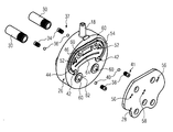
図1は、ポンプモジュールである本発明に係る実施形態の基本的な部品を示す。ポンプモジュールはケーシング基部2を備えており、ケーシング基部2は、ケーシング基部2内に2つのプランジャ体4を収容して、これらを往復移動可能なように囲んでいる。更に、本発明の意味の範囲内で緊締要素の実施形態である4つの緊締ねじ6が示されており、緊締ねじ6は、組み立てられた状態で、本発明のトランスポンダユニットの例である環状のRFID要素12が介在しながら、ケーシング基部2に収容されたポンプユニット10の前方に配置されたヘッド要素8と係合する。この目的のためにケーシング基部2は、ケーシング基部2に円筒状の座部として構成された放出領域14を有しており、ポンプユニット10の入口ポート18を受けるよう構成された軸スロット16が形成されている。ケーシング基部2は同様に、放出領域14の反対側の端部で開口し、駆動領域20を形成している。
FIG. 1 shows the basic components of an embodiment according to the invention which is a pump module. The pump module includes a
図1から分かるように、ケーシング基部2は、実質的に円筒状に形成されている。ケーシング基部2の外周面には、ケーシング基部2の軸方向に延びる溝22と、溝22から分岐して溝22に対して横方向に延びる横断溝24とが形成されており、溝22及び横断溝24はポンプモジュールを駆動ケーシングに取り付けるためのガイド・ロック面を示す。その詳細は、図18以降及び関連する説明に示されている。
As can be seen from FIG. 1, the
ポンプユニット10は、バルブブロック26と、バルブブロック26に当接するカバー要素28とによって形成されており、2つのシリンダ挿入体30が、カバー要素28の反対側でバルブブロック26から突出しており、1つのシリンダ挿入体30のみが図1に示されている。2つのシリンダ挿入体30は、送出動作中にプランジャ体4と相互作用する。この目的のために、プランジャ体4の各々は、密閉リングの形態の密閉要素32を支持しており、密閉要素32は、プランジャ体4の前方の自由端部の領域でプランジャ体4にポジティブフィットするように保持されている。
The
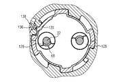
図2は、2つのシリンダ挿入体30がバルブブロック26に対向する端部に波状の外形を外周部に有することを示しており、シリンダ挿入体30は、シリンダ挿入体30の密閉状態での挿入のためにバルブブロック26内に形成されている。夫々のバルブライナ34が、シリンダ挿入体30及びバルブブロック26の間に設けられ、バルブボール36と共に出口バルブ37を夫々形成している。バルブライナ38が、関連付けられたバルブボール40と共にシリンダ挿入体30の反対側に示されており、夫々のシリンダ挿入体30への入口バルブ41を形成している。入口バルブ41は、バルブブロック26に凹設されて入口通路44と連通する入口バルブ口42内に受け入れられ、入口通路44は、一側が開口したU字形の溝として突起部46に凹設され、カバー要素28によって覆われている。出口バルブ37は、対応する出口バルブ口内に取り付けられており、出口バルブ口の1つが図9に一例として示されており、参照符号50が付されている。図2に示すように、バルブブロック26には入口ポート18が一体的に形成されている。カバー要素28に面した側から、直径が異なる2つの嵌合要素52が突起部46によって形成された密閉面54から突き出て密閉面54を超えて突出している。カバー要素28は、バルブブロック26に対してカバー要素28を正確に位置決めするよう機能する、これらの嵌合要素52に適した嵌合孔56を有する。シリンダ挿入体30をバルブブロック26に組み立てるとき、ポカヨケ機能によってカバー要素28が常に正しい向き及び位置に配置されるように、嵌合要素52及び嵌合孔56は相互に適した直径を有している。
FIG. 2 shows that the two cylinder inserts 30 have a wave-like outer shape at the end facing the
これら2つの嵌合孔56に加えて、カバー要素28は更に出口孔58を有している。
In addition to these two
バルブブロック26は、緊締ねじ6に対応する4つの貫通孔60を有しており、貫通孔60は、まず、突起部46によって形成された密閉面54を貫通し、次に、カバー要素28に当接するように構成されて同じ高さに設けられている環状面62を貫通する。カバー要素28は、環状面62及び密閉面54に密閉状態で当接し、レーザビーム溶接によって環状面62及び密閉面54に溶接される。この目的のために、カバー要素28はレーザ透過性材料から形成され、バルブブロック46はレーザビームを吸収するプラスチック材料から形成される。従って、両方の部品をレーザ透過溶接によって連結することができ、プラスチック材料から形成されたカバー要素28は、バルブブロックとの境界部分で、物質がポジティブフィットするようにバルブブロック26のプラスチック材料に連結される。これにより、入口通路44と、参照番号64によって示されてバルブブロック26に凹んでいるU字状のチャネルを有し、カバー要素28によって覆われる出口通路とが形成されている。出口通路64は、ヘッド要素8に一体的に形成されている出口ポートブッシュ66と出口孔58を介して連通しており、出口ポートブッシュ66は、出口孔58の軸方向の延長部分に設けられており、ルアー連結部分を形成するために外周部に雄ねじを有している。従って、圧力ホースが、ルアー連結部分によって出口ポートブッシュ66に簡単に連結され得る。
The
図4は、ケーシング基部2及び駆動領域20の対向側端部を上から見た斜視側面図である。プランジャ体4は、ケーシング基部2によって取り囲まれ、その一端部が駆動領域20に突出している。特に図5に示されているように、駆動側のプランジャ体4の端部は、ハンマーヘッド68の形状のポジティブフィット要素を形成しており、端部側でケーシング基部2を越えて突出している。しかしながら、プランジャ体4は他の部分ではケーシング基部によって軸方向に覆われている(図5参照)。
FIG. 4 is a perspective side view of the
図4、図5、図6及び図11から分かるように、ケーシング基部2は壁厚が比較的均一な射出成形部材として構成されているため、ケーシング基部2の射出成形中に良好な固化挙動が得られる。モジュールの部品を製造するためのプラスチック材料をPA、PE、PP及び/又はPOMとすることができ、例えば鉱物及び/又は繊維が充填された充填プラスチックとしてもよい。この目的のために、ケーシング基部2は、ケーシング基部2の外周面にラジアルウェブ72を介して連結された中心凹部70を有しており、ラジアルウェブ72は多角形構造74から分岐しており、多角形構造74は、ラジアルウェブ72間のガイドスリーブ76を夫々のプランジャ体4に対して内側で連結しており、ガイドスリーブ76は、ケーシング基部2の外周面に更なるラジアルウェブ78を介して支持されている(図16参照)。
As can be seen from FIGS. 4, 5, 6, and 11, the
ケーシング基部2は径方向に延びる隔壁80を形成しており、この隔壁80には特に緊締ねじ6用の通路口82が設けられている(図17参照)。緊締ねじ6は、隔壁80、バルブブロック26及びカバー要素28を完全に貫通してヘッド要素8 に部分的に挿入しており、ヘッド要素8とねじ作用で係合する。この目的のために、緊締ねじ6はセルフタップ式である。ヘッド要素8は更に、放出領域14のケーシング基部2によって形成された凹部に溶接され得るため、バルブブロック26及びカバー要素28に間接的に連結され得る。密閉リング83が、出口ポートブッシュ66により形成された通路をカバー要素28の出口孔58に対して密閉する(図1及び図5参照)。
The
ガイドスリーブ76の軸方向の延長部分に、ケーシング基部2は、隔壁80に達するシリンダ挿入体受入口84を形成しており、シリンダ挿入体受入口84はシリンダ挿入体30を受けるように形成されており、バルブブロック26の突き出ているリングカラー86が内嵌する環状の空間をシリンダ挿入体30とケーシング基部2の材料との間に形成するために、略隔壁80の高さで径方向に厚くなっている。このリングカラー86は、例えば、図6及び図8に示されている。リングカラー86は、シリンダ挿入体30とバルブブロック26との間に密閉連結部分を画定すべく機能する。図8に示されているように、シリンダ挿入体30の波状の外形の外周面が、リングカラー86内に収容されて更にリングカラー86とポジティブにロックされる。各シリンダ挿入体30は、押圧によってリングカラー86に挿入されるため、バルブブロック26に密閉状態で連結される。
The
隔壁80は更に、バルブブロック26に向かって開口してRFIDリング12を受けるように形成されている環状溝を形成しており、このRFIDリング12が隔壁80とバルブブロック26との間に配置され得る(図5参照)。図5はこの環状溝の下部で、データキャリアを表すRFIDリング12が厚いことを示している。径方向により細いRFIDリング12の領域の残り部分は、ケーシング基部2内に適切に置くために機能し(図1参照)、例えばハンドピースから出力される信号を増幅するためのコイルとして更に機能しており、RFIDリング12と共に、ハンドピースに取り付けられたノズルの形状のタイプが示されている。
The
図5及び図13に示すように、バルブブロック26は、壁厚が同一の部品として更に構成されており、従って、プラスチック射出成形によって適切に製造され得る。特に図5は、プランジャ体4の運動方向に延びている支持リブ88の幾つかを示しており、支持リブ88は、隔壁80に支持され、緊締ねじ6のための通路口92を形成するスリーブ部分90を連結しており、通路口92は、隔壁80を通って通路口82と同一平面である。上述したスリーブ部分90は、カバー要素28と当接するための上記の環状面62を形成している。
As shown in FIGS. 5 and 13, the
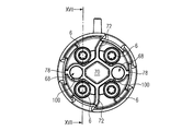
図14及び図15は、バルブブロック26内の入口バルブ41及び出口バルブ37の配置を示している。このバルブブロック26は、対応するバルブライナ34,38を受けるように構成された入口バルブ口42及び出口バルブ口50を有しており、入口バルブ口42及び出口バルブ口50は夫々、バルブボール36及びバルブボール40が夫々位置付けられる受入空間94を流体の流れ方向の下流側に有している。バルブが閉じた状態では、このバルブボール36及びバルブボール40は夫々、対応するバルブライナ34,38の、流れが無い端部によって形成されたバルブ開口部と相互作用する。図15においては、この位置は、出口バルブ37のバルブボール36のために示されている一方、入口バルブ41のバルブボール40は対応するバルブ開口部を開放している。図15は、プランジャ体4がシリンダ挿入体30内の変位を増加させて、送られる流体が入口通路44を通って押しのけチャンバに導入される一方、出口通路が出口バルブ37によって閉じられている状態を示している。夫々のバルブボール36,40は、本実施形態では受入空間94内で自由に移動可能に設けられており、バルブ開口部の直径と、バルブ開口部から分岐してバルブブロック26に形成された通路の、流れから遠い側での直径との直径比によりバルブブロック26に閉じ込めるように保持されている。組立のために、夫々のバルブボール36,40をまず受入空間94に挿入する。次に、バルブライナ34及びバルブライナ38を夫々バルブブロック26に圧入する。その後、出口バルブ37及び入口バルブ41を、バルブブロック26内に閉じ込めるように予め組み立てる。
14 and 15 show the arrangement of the
図15から更に分かるように、対向側でバルブブロック26に圧入されたシリンダ挿入体30が出口バルブ37のバルブライナ34に当接することによって、ポンプの圧力側に設けられた出口バルブ37は、更に所定の位置に固定されて、バルブライナ34への圧力嵌めにより不必要に押し出されることが防止される。
As can be further understood from FIG. 15, the
特に、図7は第1の円錐状送込デバイス96を示しており、第1の円錐状送込デバイス96は、ケーシング基部2によって形成されて、駆動領域20の方向にシリンダ挿入体30の前方に設けられている。この第1の円錐状送込デバイス96は、プランジャ体4の、密閉要素32が位置付けられている前端部が、シリンダ挿入体30によって形成されたシリンダに挿入されることを容易にする。プランジャ体4が挿入されると、密閉要素32は、シリンダ挿入体30に対して同心的に配置され、シリンダ挿入体30の略内径になる。第2の円錐状送込デバイス98が、シリンダ挿入体30自体によって形成されている。この第2の円錐状送込デバイス98内に、密閉要素32が、図6及び7に示された待機位置で位置付けられる。密閉要素32は、シリンダ挿入体30に対して径方向に離れて設けられている。このために生じる径方向の間隙によって、全ての部品が組み立てられた後、本実施形態の殺菌又は消毒のための流体及び/又はガスが通過することが可能になる。この待機位置は、本明細書ではケーシング基部2に一体的に形成された係合歯止め100によって形成されているロック要素によって定められる。この係合歯止め100は、特に図10〜12に示されている。係合歯止め100は、駆動側のガイドスリーブ76の端部を切り離すことにより形成されている。係合歯止め100は、図9及び10に示されているロック突起部102を有しており、ロック突起部102は、プランジャ体4に一部品として一体的に形成された2つのリング状突起部106,108間に形成されたロック溝104に待機位置で係合する(図10参照)。前方のリング状突起部108は、ロック溝104の略厳密に径方向に延びる側面を形成している一方、後方のリング状突起部106は傾斜した側面を有しているため、待機位置から送出位置、つまり動作位置へのプランジャ体4の前進を容易にする。送出位置、つまり動作位置では、密閉要素32は、シリンダ、ひいてはシリンダ挿入体30の内周面に密閉状態で当接する。図9及び10は最も上の送出位置を表して、図8は最も下の送出位置を表すと仮定し得る。プランジャ体4のストロークは、図8及び9に係るこれら2つの位置の間で行われる。
In particular, FIG. 7 shows a first
係合歯止め100及びロック溝104の構成によって上述した待機位置にロックする。圧力の臨界値を超えた駆動側からのプランジャ体4に対する軸方向の圧力によって、待機位置から解放されて、プランジャ体4は送出位置にケーシング内のより深くに移動する。この送出位置では、リング状突起部106,108は、更にケーシング基部2によって形成されたガイドスリーブ76にもプランジャ体4を導き(図9及び10参照)、その結果、送出動作中にプランジャ体4がより高く滑らかに動く。プランジャ体4は、特に軸方向に組み込まれるときに曲がることが防止されるため、プランジャ体4は、比較的柔らかい材料、例えばプラスチック材料から製造され得る。
The
図6に示されているように、プランジャ体4のハンマーヘッド68は待機位置でケーシング基部2を越えて突出することにより、待機位置を確認するための光学的な指標が設けられる。駆動部に接合した後、プランジャ体4が必然的に待機位置から送出位置に移されると、ハンマーヘッド68を有する駆動側の端部は夫々、ケーシング基部2内、及び駆動領域20に形成された軸方向に開いた後方の凹部内に露出する。
As shown in FIG. 6, the
本実施形態の記載に例証されているように、入口通路44及び出口通路64は、本発明に係るポンプモジュール内にシリンダ挿入体30と密閉要素32との間に形成されている。入口通路44及び出口通路64は、バルブブロック26とカバー要素28との間の境界部分内に延びている。境界部分に設けられた入口通路44は、入口ポート18の近くの上端部から導入された流体を夫々の入口バルブ41に分配する。流体は、境界部分の外縁部で入口バルブ41まで境界部分に導かれ、従って、出口通路64を少なくとも部分的に囲む。この出口通路64は、複数の出口バルブ37、この場合には2つの出口バルブ37と連通する。カバー要素28とバルブブロック26との間の境界部分内で、出口通路64は、出口ポートブッシュ66によって形成された放出通路と同一平面である収集ポイントまで加圧流体を導く。収集ポイントは、更にカバー要素28とバルブブロック26との間の境界部分内に位置付けられている。入口通路44及び/又は出口通路64の最も大きい部分は、バルブブロック26とカバー要素28との間の境界部分内に特に形成されている。この最も大きい部分は、ポンプモジュール内の夫々の通路の流路の全長の少なくとも50%、好ましくは60%に相当する。入口側のためのこの流路は、入口ポート18の入口開口部から始まり、入口バルブ41で終わる。出口側の夫々の流路は、出口ポートブッシュ66によって形成された開口部から始まり、出口バルブ37、ひいては対応する出口バルブ37の受入空間94で終わる。
As illustrated in the description of this embodiment, the
本発明の別の重要な態様は、ポンプユニット10がバルブブロック26及びカバー要素28から構成されており、出口バルブ37、入口バルブ41及びシリンダ挿入体30がポンプユニット10内に設置されているということである。このポンプユニット10は予め組み立てられている。本発明は更に、シリンダがケーシング基部2自体によって形成されているか、又はケーシング基部2に受け入れられてバルブブロック26に密閉状態で当接するシリンダ要素によって形成されている点で変更可能である。図7から明らかなカラーが、第1の円錐状送込デバイス96に続いてシリンダ挿入体に直接当接してケーシング基部2を予め組み込むと、特にケーシング基部2とバルブブロック26との間の境界部分に配置され得るOリングと共にケーシング基部2をバルブブロック26に対して押圧することにより、このように設けられたシリンダ挿入体を密閉することが想定され得る。
Another important aspect of the present invention is that the
更に、プランジャ体4が所定の軸方向の圧力で待機位置から送出位置に移動するように、プランジャ体4によって形成されたポンプピストンが固定される待機位置が定められていることが重要である。密閉要素32は、待機位置で、関連付けられたシリンダの内周面に確実に当接しない。殺菌又は消毒がシリンダ及びポンプピストンを通過して行われ得るように、密閉要素32は、ポンプモジュールの隣り合うケーシング部分から径方向に離れて一定の間隔で設けられている。ポンプモジュールの流れを導く部分は全て消毒剤又は殺菌剤で完全に覆われるため、効率的に殺菌される。
Furthermore, it is important that the standby position where the pump piston formed by the
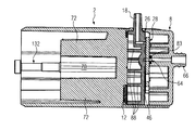
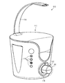
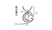
図18は、駆動ケーシング112内に設けられた電気駆動部である駆動部を有する駆動ユニット110の実施形態の斜視側面図である。ホルダ114が、流体バッグを保持するために駆動ケーシング112から突出している。駆動ケーシング112には、駆動部を作動させて駆動部をオン及びオフに切り替える機能を有する様々な制御要素116が更に露出している。参照番号118は実質的に円筒状の凹部を示しており、凹部118内に、参照番号120で示されている図1〜17に係るポンプモジュールが挿入され、凹部118は、これらの図面と比較して簡略化して示されている。ケーシング基部2は、凹部118内に内向きに突出して本発明のポジティブロック要素の実施形態である突出部122を有している。本明細書では4つの突出部122が外周に分散して設けられている。参照番号122.4によって識別される突出部は、ポンプモジュール120の固有の関連付けを可能にするために、他の突出部122.1〜122.3より小さい径方向の延長部及びより小さい周方向の延長部を有する。他のタイプのポカヨケ構成が想定され得る。互いに異なる角度オフセットを有する溝が、ケーシング、特にケーシング基部2の外周面に設けられ得るため、ポンプモジュール120が所定の方法でのみ凹部118に挿入され得る。凹部118には駆動プッシャ124の形態の更なる駆動要素が露出しており、駆動プッシャ124は、駆動ケーシング112内に設けられている駆動部に連結されて長手方向に往復移動するように駆動可能である。駆動プッシャ124は当接面126を形成する。本明細書では2つの駆動プッシャ124が設けられている。上から見てC字状の爪部128が当接面126を越えて突出し、爪部自体と当接面126との間にハンマーヘッド座部130を形成する。
FIG. 18 is a perspective side view of an embodiment of the
特に図11及び16から明らかなように、厳密に中心長手軸芯Lに沿って軸方向にケーシング基部2の外周部に延びている4つの溝22の内、参照番号22.4で示されている溝は、より小さい突出部122.4を正確に受けるように形成されている。特により小さい突出部122.4のより小さい溝22.4との相互作用により、接合するとき、つまりポンプモジュール120を凹部118に挿入するとき、ポンプモジュール120の一対一の向きが定められる。ポンプモジュール120は、図21cに示されている30°ずれた最終位置に垂直な角度でのみ挿入され得る。この回転位置は図21bに示されている。ハンマーヘッド68は、ポンプピストン4の残りの部分より小さい直径を有する各ポンプピストン4の端部側ポンプピストン部分132を越えて突出している。ハンマーヘッド68は、ポンプピストン4の対向側、つまり連結側端部を画定しており、当接面126に対する対向面134を形成している。
11 and 16, it is indicated by the reference numeral 22.4 among the four
夫々の突出部122を有するバヨネット式ロック部がまず、突出部122が溝22の内側下端部に当接するまで軸方向の挿入運動を行って、その後横断溝24内への回転運動で回転することによって軸方向にロックされるためのガイドを、溝22は横断溝24と共に形成している。横断溝24に当接する端部側の最終位置では、ポンプモジュール120が最終位置でロックされるように、ポンプモジュール120と駆動ケーシング112との回転防止ロック部を形成する歯止め突起部が動作可能である。
The bayonet-type lock portion having the respective protrusions 122 first performs an axial insertion movement until the protrusion 122 abuts the inner lower end of the
図22aには、バネアームに形成されて横断溝24に露出し、ケーシング基部2に固定して形成された歯止め・スイッチ突起部136が横断溝24内に更に示されている(図3参照)。この歯止め・スイッチ突起部136は、突出部122.2内の中心に設けられているスイッチ138と関連付けられている。スイッチ138は、凹部118に対して径方向の内側に予め組み込まれており、対応して歯止め・スイッチ突起部136と相互作用する。このスイッチ138が歯止め・スイッチ突起部136によって作動することによってのみ、駆動プッシャ124を駆動することが可能となる。従って、ポンプモジュール120が駆動ユニット1に所定の方法で連結されていない場合、駆動ユニットは作動され得ない。駆動ケーシング112は、読み取りユニットを更に有しており、読み取りユニットは、駆動ケーシング112に対するRFIDリング12、ひいてはポンプモジュール120の正確な向きを認識して、その後で初めて出力を与える。このため、スイッチ138がつなげられてデバイスが動作することが防止される。
FIG. 22a further shows in the transverse groove 24 a pawl /
図21a〜図21cは、凹部118内へのポンプモジュール120の挿入を示している。既に上述したように、ポンプモジュール120はまず、突出部122を溝22と一致させるために、最終位置に対して反時計回りの方向に30°回転する(図21a参照)。回転位置は、図3に明瞭に示され得るアライメント矢印140によって特徴付けられて、図21aではケーシング側に設けられた位置指標144と並んでいる。この相対的な向きでポンプモジュール120を凹部118内に挿入することができる。この軸方向の挿入運動は、突出部122に対応して形成された溝22に係合する突出部122によって導かれる。図21bに係る例では、図21bに直線の矢印で示されているこの軸方向の挿入が終了する。この時点で、ポンプモジュール120が凹部118内に完全に挿入されている。その後、図21cの矢印によって示されているように、ポンプモジュール120は時計回りの方向に30°回転する。この30°の回転運動の後、ポンプモジュール120は最終位置に達する。この最終位置は、ケーシング基部2の外周部に設けられている方向矢印142であって駆動ケーシング112に設けられている位置指標144と最終位置で並ぶ方向矢印142によってユーザに示される。方向矢印142は、ポンプモジュール120を凹部118内に挿入する方向をも示す。
FIGS. 21 a-c show the insertion of the
ポンプモジュール120及び駆動ケーシング112を接合すると、駆動プッシャ124及びポンプピストン4は互いに近くなる。突出部122が溝22内で軸方向に導かれることによって、ハンマーヘッド68によって形成される対向面134は、駆動プッシャ124によって形成される当接面126の上側に少なくとも部分的に位置付けられる(図22a参照)。連続的な軸方向の運動によって最終的に、ポンプピストン4が端部側で当接面126に当接する。ポンプモジュール120が駆動ケーシング112に接近し続けると、待機位置から解放されて、ポンプピストン4は送出位置にケーシング基部2内のより深くに押し込められる。その後、関連付けられたポンプピストン4と駆動プッシャ124との更なる相対的な軸方向運動は生じない。
When the
2つのポンプピストン4夫々のハンマーヘッド68は駆動プッシャ124の中心に対して偏心した位置に位置付けられる。これは図22aに示されている。ケーシング基部2は一般的に、両方のポンプピストン4が駆動プッシャ124に軸方向に当接した後、駆動ケーシング112に対して軸方向に更に僅かな距離だけ移動するので、ケーシング基部2が駆動ケーシング112に対して回転する前であってポンプモジュール120と駆動ケーシング112とを接合するときに軸方向の最終位置に達するまで、駆動プッシャ124に対するポンプピストン4の軸方向の当接が常に確実に達成されることが保証されている。この構成によって、軸方向の挿入運動が完了した後に駆動プッシャ124の全ての想定され得る位置で、駆動プッシャ124の位置が凹部118内の最も低い位置にある場合でさえ、駆動プッシャ124に対するポンプピストン4の確実な当接が確かに得られる。
The
この軸方向の最終位置に達した後、ポンプモジュール120は時計回りの方向に回転する。この回転運動の中心に対して偏心して配置されているハンマーヘッド68はこの回転によって、図22a〜図22cに示されているように、ハンマーヘッド68の対向面134により当接面126で摺動するように駆動プッシャ124に対して移動し、すなわち挿入方向に垂直に延びる面内で駆動プッシャ124に対して移動する。図22aに示されている駆動プッシャ124に対するポンプピストン4の以前の偏心配置は、その後、図22bに示されている中間位置を介して図22cに示されている最終位置に近付く。この最終位置で、突出部122は、横断溝24によって形成されているストッパに当接する。ケーシング基部2は一般的に、駆動ケーシング112に対してロックされる。ポンプピストン4は、駆動プッシャ124に対して実質的に同心に配置される。各爪部128は、関連付けられているハンマーヘッド68に係合する。ハンマーヘッド68は、爪部128を有するハンマーヘッド座部130の係合によって軸方向にポジティブロックのように保持される。ハンマーヘッド座部130は一般的にハンマーヘッド68の高さに軸方向に正確に一致するため、駆動プッシャ124とポンプピストン4との遊びのない軸方向のポジティブロック連結が生じる。
After reaching this axial final position, the
2 ケーシング基部
4 プランジャ体/ポンプピストン
6 緊締ねじ
8 ヘッド要素
10 ポンプユニット
12 RFIDリング
14 放出領域
16 軸スロット
18 入口ポート
20 駆動領域
22 溝
24 横断溝
26 バルブブロック
28 カバー要素
30 シリンダ挿入体
32 密閉要素
34 バルブライナ
36 バルブボール
37 出口バルブ
38 バルブライナ
40 バルブボール
41 入口バルブ
42 入口バルブ口
44 入口通路
46 突起部
50 出口バルブ口
52 嵌合要素
54 密閉面
56 嵌合孔
58 出口孔
60 貫通孔
62 環状面
64 出口通路
66 出口ポートブッシュ
68 ハンマーヘッド
70 中心凹部
72 ラジアルウェブ
74 多角形構造
76 ガイドスリーブ
78 更なるラジアルウェブ
80 隔壁
82 通路口
83 密閉リング
84 シリンダ挿入体受入口
86 リングカラー
88 支持リブ
90 スリーブ部分
92 通路口
94 受入空間
96 第1のテーパ状送込デバイス
98 第2のテーパ状送込デバイス
100 係合歯止め
102 ロック突起部
104 ロック溝
106 リング状突起部
108 リング状突起部
110 駆動ユニット
112 駆動ケーシング
114 ホルダ
116 制御要素
118 凹部
120 ポンプモジュール
122 突出部
124 駆動プッシャ
126 当接面
128 爪部
130 ハンマーヘッド座部
132 ポンプピストン部
134 対向面
135 バネアーム
136 歯止め・スイッチ突起部
138 スイッチ
140 アライメント矢印
142 方向矢印
144 位置指標
L 中心長手軸芯
2
Claims (15)
シリンダと、
送出動作中に前記シリンダと相互作用する少なくとも1つの密閉要素を有し、前記ポンプケーシング内で往復移動可能なように取り付けられている少なくとも1つのポンプピストンと、
前記シリンダに対して密閉され、前記シリンダに対する少なくとも1つのバルブを受けるバルブブロックと、
前記シリンダの反対側で前記バルブブロックに当接し、前記シリンダへの入口通路及び/又は前記シリンダと連通する出口通路を自身と前記バルブブロックとの間に形成しているカバー要素と
を備えていることを特徴とするポンプモジュール。 A pump casing;
A cylinder,
At least one pump piston having at least one sealing element that interacts with the cylinder during a delivery operation, and is mounted for reciprocation within the pump casing;
A valve block sealed to the cylinder and receiving at least one valve for the cylinder;
A cover element that abuts the valve block on the opposite side of the cylinder and forms an inlet passage to the cylinder and / or an outlet passage communicating with the cylinder between itself and the valve block. A pump module characterized by that.
前記入口通路は、前記出口通路を少なくとも部分的に周方向に囲むように前記境界部分内に形成されていることを特徴とする請求項1乃至8のいずれか一項に記載のポンプモジュール。 The inlet passage provided in the boundary between the cover element and the valve block is in communication with at least two cylinders;
9. The pump module according to claim 1, wherein the inlet passage is formed in the boundary portion so as to at least partially surround the outlet passage in the circumferential direction.
駆動ケーシング内に設けられている駆動部と、
請求項1乃至14のいずれか一項に記載のポンプケーシングを有するポンプモジュールと
を備えており、
前記駆動ケーシング及び前記ポンプモジュールは着脱可能に接合可能であり、
前記駆動部及び前記ポンプモジュールは相互に割り当てられた電子識別部分を有していることを特徴とするデバイス。 A device for generating a fluid jet, particularly for removing biological tissue,
A drive unit provided in the drive casing;
A pump module having the pump casing according to any one of claims 1 to 14,
The drive casing and the pump module can be detachably joined,
The device according to claim 1, wherein the drive unit and the pump module have electronic identification parts assigned to each other.
Applications Claiming Priority (2)
| Application Number | Priority Date | Filing Date | Title |
|---|---|---|---|
| EP16174463.6A EP3258101B1 (en) | 2016-06-14 | 2016-06-14 | Pump module and device for producing a fluid jet |
| EP16174463.6 | 2016-06-14 |
Publications (2)
| Publication Number | Publication Date |
|---|---|
| JP2017223231A true JP2017223231A (en) | 2017-12-21 |
| JP6405001B2 JP6405001B2 (en) | 2018-10-17 |
Family
ID=56194278
Family Applications (1)
| Application Number | Title | Priority Date | Filing Date |
|---|---|---|---|
| JP2017117187A Active JP6405001B2 (en) | 2016-06-14 | 2017-06-14 | Pump module and device for generating a fluid jet |
Country Status (5)
| Country | Link |
|---|---|
| US (1) | US10550839B2 (en) |
| EP (1) | EP3258101B1 (en) |
| JP (1) | JP6405001B2 (en) |
| CN (1) | CN107503932B (en) |
| ES (1) | ES2758796T3 (en) |
Citations (6)
| Publication number | Priority date | Publication date | Assignee | Title |
|---|---|---|---|---|
| JPS5657975U (en) * | 1979-10-11 | 1981-05-19 | ||
| JPH09177973A (en) * | 1995-12-20 | 1997-07-11 | Tokico Ltd | Reciprocating compressor |
| JP2004204769A (en) * | 2002-12-25 | 2004-07-22 | Takubo Engineering Co Ltd | Syringe pump |
| JP2009503346A (en) * | 2005-08-04 | 2009-01-29 | リンデ アクチエンゲゼルシヤフト | Unit-type fluid pressure machine with valve plate |
| JP2009287570A (en) * | 2009-09-07 | 2009-12-10 | Mitsubishi Heavy Ind Ltd | Boosting pump for low temperature fluid |
| JP2014061376A (en) * | 2012-09-19 | 2014-04-10 | Erbe Elektromedizin Gmbh | Pump unit for water jet surgical operation |
Family Cites Families (19)
| Publication number | Priority date | Publication date | Assignee | Title |
|---|---|---|---|---|
| DE2910946A1 (en) * | 1979-03-20 | 1980-10-02 | Siemens Ag | DOSING SYRINGE |
| NO168134C (en) * | 1989-05-16 | 1992-01-15 | Alcatel Stk As | GAS DRIVE PUMP PUMP FOR OIL |
| US5451145A (en) * | 1993-11-05 | 1995-09-19 | Sauter; William | High pressure fluid pump transformer and method |
| IT239544Y1 (en) * | 1995-07-14 | 2001-03-05 | Lavorwash S R L | STRUCTURE OF PUMP WITH ROTARY PLATE, PARTICULARLY HYDROPULITRICI |
| US6095758A (en) * | 1998-03-30 | 2000-08-01 | Chou; Wen-San | Structure for a compact air compressor |
| CA2484061C (en) | 2001-04-27 | 2008-07-15 | Hydrocision, Inc. | High pressure pumping cartridges for medical and surgical pumping and infusion applications |
| DE10160168B4 (en) * | 2001-12-07 | 2007-08-30 | Uraca Pumpenfabrik Gmbh & Co Kg | central valve |
| JP3960253B2 (en) | 2002-04-17 | 2007-08-15 | 株式会社日立製作所 | Optical switch and beam direction module |
| ITPD20030053U1 (en) | 2003-07-10 | 2005-01-11 | Lavorwash Spa | HYDRAULIC PISTON AXIAL STRUCTURE |
| DE102006053609A1 (en) | 2006-11-14 | 2008-05-15 | Erbe Elektromedizin Gmbh | Medical pump |
| DE102007003521B4 (en) * | 2007-01-18 | 2011-06-09 | Alfred Kärcher Gmbh & Co. Kg | Piston pump for a high-pressure cleaner |
| DE102008014205B4 (en) * | 2008-03-14 | 2013-05-29 | Beko Technologies Gmbh | Integrated catalyst |
| DE202008004289U1 (en) * | 2008-03-27 | 2010-04-08 | Mann+Hummel Gmbh | Filter lock system with bayonet |
| KR100963557B1 (en) * | 2008-06-11 | 2010-06-15 | 한국기계연구원 | Self reciprocated energy recovery device |
| CN201209546Y (en) * | 2008-07-01 | 2009-03-18 | 陈人德 | Single pump piston type double-acting air-pumping device for air compressor |
| EP2427655B1 (en) * | 2009-05-08 | 2014-01-08 | Xavitech AB | A membrane pump |
| US8337175B2 (en) | 2009-12-22 | 2012-12-25 | Smith & Nephew, Inc. | Disposable pumping system and coupler |
| JP6080976B2 (en) * | 2012-12-20 | 2017-02-15 | ローベルト ボツシユ ゲゼルシヤフト ミツト ベシユレンクテル ハフツングRobert Bosch Gmbh | Piston fuel pump for internal combustion engines |
| PL2924285T3 (en) * | 2014-03-26 | 2018-03-30 | Erbe Elektromedizin Gmbh | Sterilisable pump unit |
-
2016
- 2016-06-14 EP EP16174463.6A patent/EP3258101B1/en active Active
- 2016-06-14 ES ES16174463T patent/ES2758796T3/en active Active
-
2017
- 2017-06-13 CN CN201710443843.2A patent/CN107503932B/en active Active
- 2017-06-14 US US15/622,469 patent/US10550839B2/en active Active
- 2017-06-14 JP JP2017117187A patent/JP6405001B2/en active Active
Patent Citations (6)
| Publication number | Priority date | Publication date | Assignee | Title |
|---|---|---|---|---|
| JPS5657975U (en) * | 1979-10-11 | 1981-05-19 | ||
| JPH09177973A (en) * | 1995-12-20 | 1997-07-11 | Tokico Ltd | Reciprocating compressor |
| JP2004204769A (en) * | 2002-12-25 | 2004-07-22 | Takubo Engineering Co Ltd | Syringe pump |
| JP2009503346A (en) * | 2005-08-04 | 2009-01-29 | リンデ アクチエンゲゼルシヤフト | Unit-type fluid pressure machine with valve plate |
| JP2009287570A (en) * | 2009-09-07 | 2009-12-10 | Mitsubishi Heavy Ind Ltd | Boosting pump for low temperature fluid |
| JP2014061376A (en) * | 2012-09-19 | 2014-04-10 | Erbe Elektromedizin Gmbh | Pump unit for water jet surgical operation |
Also Published As
| Publication number | Publication date |
|---|---|
| CN107503932B (en) | 2019-10-18 |
| EP3258101A1 (en) | 2017-12-20 |
| CN107503932A (en) | 2017-12-22 |
| US10550839B2 (en) | 2020-02-04 |
| US20170356443A1 (en) | 2017-12-14 |
| ES2758796T3 (en) | 2020-05-06 |
| EP3258101B1 (en) | 2019-09-11 |
| JP6405001B2 (en) | 2018-10-17 |
Similar Documents
| Publication | Publication Date | Title |
|---|---|---|
| US11284980B2 (en) | Oral cleansing device with rotatable fluid connector | |
| JP6262390B2 (en) | Pump module | |
| EP2032269A2 (en) | Pumps and methods for using the same | |
| KR100580900B1 (en) | Plurality of vacuum generation units | |
| JP5242677B2 (en) | Refill pack for personal use equipment | |
| JP6405001B2 (en) | Pump module and device for generating a fluid jet | |
| CN106468363B (en) | Disposable diaphragm valve | |
| US8382451B2 (en) | Pump apparatus | |
| US9494144B2 (en) | Piston pump for a high-pressure cleaning appliance | |
| WO2007111230A1 (en) | Fuel injection device | |
| US9938971B2 (en) | Self-locking coupling between a pump casing and a pump module | |
| CN105917197B (en) | Fluid dose measuring device | |
| CN218479907U (en) | Pump head device of tooth flushing device and tooth flushing device | |
| JP2022006707A (en) | Adhesive pumping device | |
| CN210277849U (en) | Medical pulse flusher | |
| KR101839526B1 (en) | Reciprocating metering pump | |
| CN109964073B (en) | Lubricant cartridge container and lubricant supply system provided with same | |
| CN217390664U (en) | Cleaning device | |
| CN110892263A (en) | Plunger pump | |
| CN218187213U (en) | Continuous water supply device and dental chair equipment | |
| KR100296287B1 (en) | Piston | |
| KR102351342B1 (en) | Pressure detector for interlink pump of drug spray | |
| KR102355756B1 (en) | Spray gun | |
| JP3692372B2 (en) | Multiple power sprayer | |
| CN114680787A (en) | Cleaning device |
Legal Events
| Date | Code | Title | Description |
|---|---|---|---|
| A131 | Notification of reasons for refusal |
Free format text: JAPANESE INTERMEDIATE CODE: A131 Effective date: 20180508 |
|
| A521 | Request for written amendment filed |
Free format text: JAPANESE INTERMEDIATE CODE: A523 Effective date: 20180808 |
|
| TRDD | Decision of grant or rejection written | ||
| A01 | Written decision to grant a patent or to grant a registration (utility model) |
Free format text: JAPANESE INTERMEDIATE CODE: A01 Effective date: 20180821 |
|
| A61 | First payment of annual fees (during grant procedure) |
Free format text: JAPANESE INTERMEDIATE CODE: A61 Effective date: 20180913 |
|
| R150 | Certificate of patent or registration of utility model |
Ref document number: 6405001 Country of ref document: JP Free format text: JAPANESE INTERMEDIATE CODE: R150 |
|
| R250 | Receipt of annual fees |
Free format text: JAPANESE INTERMEDIATE CODE: R250 |
|
| R250 | Receipt of annual fees |
Free format text: JAPANESE INTERMEDIATE CODE: R250 |
|
| R250 | Receipt of annual fees |
Free format text: JAPANESE INTERMEDIATE CODE: R250 |