JP2017222279A - Travel route generation method and travel route generation apparatus - Google Patents

Travel route generation method and travel route generation apparatus Download PDF

Info

Publication number
JP2017222279A
JP2017222279A JP2016119705A JP2016119705A JP2017222279A JP 2017222279 A JP2017222279 A JP 2017222279A JP 2016119705 A JP2016119705 A JP 2016119705A JP 2016119705 A JP2016119705 A JP 2016119705A JP 2017222279 A JP2017222279 A JP 2017222279A
Authority
JP
Japan
Prior art keywords
target
parking frame
travel route
route generation
target position
Prior art date
Legal status (The legal status is an assumption and is not a legal conclusion. Google has not performed a legal analysis and makes no representation as to the accuracy of the status listed.)
Granted
Application number
JP2016119705A
Other languages
Japanese (ja)
Other versions
JP6673043B2 (en
Inventor
三浦 雅博
Masahiro Miura
雅博 三浦
明之 後藤
Akinobu Goto
明之 後藤
Current Assignee (The listed assignees may be inaccurate. Google has not performed a legal analysis and makes no representation or warranty as to the accuracy of the list.)
Nissan Motor Co Ltd
Original Assignee
Nissan Motor Co Ltd
Priority date (The priority date is an assumption and is not a legal conclusion. Google has not performed a legal analysis and makes no representation as to the accuracy of the date listed.)
Filing date
Publication date
Application filed by Nissan Motor Co Ltd filed Critical Nissan Motor Co Ltd
Priority to JP2016119705A priority Critical patent/JP6673043B2/en
Publication of JP2017222279A publication Critical patent/JP2017222279A/en
Application granted granted Critical
Publication of JP6673043B2 publication Critical patent/JP6673043B2/en
Active legal-status Critical Current
Anticipated expiration legal-status Critical

Links

Images

Abstract

PROBLEM TO BE SOLVED: To provide a travel route generation method and a travel route generation apparatus, which enable an autonomous parking with a pavement width effectively used.SOLUTION: In the case of a parking frame detection part 74 detecting a parking frame, a target recalculation part 75 recalculates a target position and a target attitude enabling a lateral movement toward the parking frame. A change part 76 changes to the target position and target attitude that are recalculated by the target recalculation part 75 from a target position and a target attitude computed by a target computation part 73. A target route generation part 77 generates a target route for parking. Further, a vehicle control part 80 controls an actuator 90 to realize an autonomous parking along the target route.SELECTED DRAWING: Figure 1

Description

本発明は、走行経路生成方法及び走行経路生成装置に関する。   The present invention relates to a travel route generation method and a travel route generation device.

従来より、車両が走行する経路を車両自体が生成する技術が知られている(特許文献1)。特許文献1は、前方の障害物を避けるために、通常経路から外れる走行経路(仮想障害物の間を通る走行経路)を短時間で生成することを開示している。   Conventionally, a technique in which a vehicle itself generates a route along which the vehicle travels is known (Patent Document 1). Patent Document 1 discloses that a travel route deviating from a normal route (a travel route passing between virtual obstacles) is generated in a short time in order to avoid obstacles ahead.

特開2015−57688号公報Japanese Patent Laying-Open No. 2015-57688

ここで、自律的に駐車する自律走行車両に特許文献1の技術を適用することを考えた場合、特許文献1は仮想障害物の間を通過する際の車両姿勢に言及していない。そのため、通常経路から外れて駐車枠付近に幅寄せを行い、車路幅を有効活用した駐車を可能にできるとはいえない。   Here, when applying the technique of patent document 1 to the autonomous traveling vehicle which parks autonomously, patent document 1 does not mention the vehicle attitude | position at the time of passing between virtual obstacles. For this reason, it cannot be said that the vehicle can be parked by deviating from the normal route and performing the width adjustment in the vicinity of the parking frame to effectively utilize the road width.

本発明は、上記問題に鑑みて成されたものであり、その目的は、車路幅を有効活用した自律駐車を行うことができる走行経路生成方法及び走行経路生成装置を提供することである。   The present invention has been made in view of the above problems, and an object of the present invention is to provide a travel route generation method and a travel route generation device that can perform autonomous parking effectively utilizing a road width.

本発明の一態様に係る走行経路生成方法は、駐車枠を検出したとき、駐車枠を検出する前の走行経路における目標位置及び目標姿勢から、駐車枠に幅寄せ可能な目標位置及び目標姿勢に変更する。   In the travel route generation method according to one aspect of the present invention, when a parking frame is detected, the target position and the target posture on the travel route before detecting the parking frame are changed to the target position and the target posture that can be brought closer to the parking frame. change.

本発明によれば、車路幅を有効活用した自律駐車を行うことができる。   ADVANTAGE OF THE INVENTION According to this invention, the autonomous parking which utilized the road width effectively can be performed.

図1は、本発明の実施形態に係る走行経路生成装置の構成図である。FIG. 1 is a configuration diagram of a travel route generation device according to an embodiment of the present invention. 図2は、通常走行における目標経路の生成方法を説明する図である。FIG. 2 is a diagram for explaining a method for generating a target route in normal traveling. 図3Aは、通常走行中に駐車枠を検出した場合の処理を説明する図である。FIG. 3A is a diagram illustrating processing when a parking frame is detected during normal traveling. 図3Bは、通常走行中に駐車枠を検出した場合の処理を説明する図である。FIG. 3B is a diagram illustrating processing when a parking frame is detected during normal traveling. 図3Cは、通常走行中に駐車枠を検出した場合の処理を説明する図である。FIG. 3C is a diagram illustrating processing when a parking frame is detected during normal traveling. 図4は、本発明の実施形態に係る走行経路生成装置の一動作例を説明するフローチャートである。FIG. 4 is a flowchart for explaining an operation example of the travel route generation device according to the embodiment of the present invention.

以下、本発明の実施形態について、図面を参照して説明する。図面の記載において同一部分には同一符号を付して説明を省略する。   Hereinafter, embodiments of the present invention will be described with reference to the drawings. In the description of the drawings, the same portions are denoted by the same reference numerals, and description thereof is omitted.

図1を参照して本実施形態に係る走行経路生成装置1の構成について説明する。走行経路生成装置1は、自律運転機能を有する自律運転車両に適用される。図1に示すように、走行経路生成装置1は、GPS受信機10と、地図データベース20と、空間認識センサ30と、操舵角センサ40と、車輪速センサ50と、車両状態量センサ60と、コントローラ70と、車両制御部80と、アクチュエータ90とを備える。   A configuration of the travel route generation device 1 according to the present embodiment will be described with reference to FIG. The travel route generation device 1 is applied to an autonomous driving vehicle having an autonomous driving function. As shown in FIG. 1, the travel route generation device 1 includes a GPS receiver 10, a map database 20, a space recognition sensor 30, a steering angle sensor 40, a wheel speed sensor 50, a vehicle state quantity sensor 60, A controller 70, a vehicle control unit 80, and an actuator 90 are provided.

GPS受信機10は、人工衛星からの電波を受信することにより、車両の現在地を検知する。GPS受信機10は、検知した現在地をコントローラ70に出力する。   The GPS receiver 10 detects the current location of the vehicle by receiving radio waves from an artificial satellite. The GPS receiver 10 outputs the detected current location to the controller 70.

地図データベース20には、道路情報や施設情報などの地図情報が記憶されている。地図データベース20は、車両に搭載されるカーナビゲーション装置に記憶されていてもよいし、サーバ上に記憶されていてもよい。地図データベース20がサーバ上に記憶されている場合、コントローラ70は、通信により随時地図情報を取得することができる。   The map database 20 stores map information such as road information and facility information. The map database 20 may be stored in a car navigation device mounted on the vehicle, or may be stored on a server. When the map database 20 is stored on the server, the controller 70 can acquire map information at any time by communication.

空間認識センサ30は、例えばレーザーレーダである。空間認識センサ30は、車両とその周囲の物体との距離を検出し、距離情報をポイントクラウド情報として取得する。空間認識センサ30は、取得したポイントクラウド情報をコントローラ70に出力する。   The space recognition sensor 30 is a laser radar, for example. The space recognition sensor 30 detects the distance between the vehicle and surrounding objects, and acquires the distance information as point cloud information. The space recognition sensor 30 outputs the acquired point cloud information to the controller 70.

操舵角センサ40は、ステアリングホイールの操舵方向と操舵角を検出し、検出した操舵方向と操舵角をコントローラ70に出力する。車輪速センサ50は、車両の速度を検出し、検出した速度をコントローラ70に出力する。車両状態量センサ60は、車両の状態量を計測するセンサであり、例えば車両のヨーレートを検出するヨーレートセンサや加速度センサなどで構成される。車両状態量センサ60は、検出した車両状態量をコントローラ70に出力する。   The steering angle sensor 40 detects the steering direction and steering angle of the steering wheel, and outputs the detected steering direction and steering angle to the controller 70. The wheel speed sensor 50 detects the speed of the vehicle and outputs the detected speed to the controller 70. The vehicle state quantity sensor 60 is a sensor that measures the state quantity of the vehicle, and includes, for example, a yaw rate sensor or an acceleration sensor that detects the yaw rate of the vehicle. The vehicle state quantity sensor 60 outputs the detected vehicle state quantity to the controller 70.

コントローラ70は、GPS受信機10や空間認識センサ30などから取得したデータを処理する回路であり、例えばCPU、ROM、RAMおよび入出力インターフェースなどから成るマイクロコンピュータである。コントローラ70は、これを機能的に捉えた場合、走路境界推定部71と、走行空間設定部72と、目標演算部73と、変更部76と、駐車枠検出部74と、目標再計算部75と、目標経路生成部77とに分類することができる。   The controller 70 is a circuit that processes data acquired from the GPS receiver 10, the space recognition sensor 30, and the like, and is, for example, a microcomputer including a CPU, a ROM, a RAM, an input / output interface, and the like. When the controller 70 grasps this functionally, the road boundary estimation unit 71, the travel space setting unit 72, the target calculation unit 73, the change unit 76, the parking frame detection unit 74, and the target recalculation unit 75. And the target route generation unit 77.

走路境界推定部71は、空間認識センサ30から取得したポイントクラウド情報を用いて走路の境界を推定する。例えば、走路境界推定部71は、駐車車両の並びから走路の境界を推定する。   The road boundary estimation unit 71 estimates the boundary of the road using the point cloud information acquired from the space recognition sensor 30. For example, the road boundary estimation unit 71 estimates the road boundary from the arrangement of parked vehicles.

走行空間設定部72は、走路境界推定部71によって推定された走路の境界で挟まれた空間を、車両が走行可能な空間として設定する。また、走行空間設定部72は、走路の境界で挟まれた空間において、車両が周囲の物体と接触することなく走行できるように走行可能空間における車路幅や走路の向きを設定する。   The traveling space setting unit 72 sets a space sandwiched between the traveling road boundaries estimated by the traveling road boundary estimation unit 71 as a space in which the vehicle can travel. In addition, the travel space setting unit 72 sets the vehicle width and the direction of the travel path in the travelable space so that the vehicle can travel without contacting the surrounding objects in the space between the travel path boundaries.

目標演算部73は、走行空間設定部72によって設定された走行可能空間を走行するための目標位置及びその目標位置における目標姿勢を演算する。目標姿勢とは、車体が目標とする姿勢である。なお、以下では、目標位置及びその目標位置における目標姿勢を、単に目標位置及び目標姿勢と表現する。   The target calculation unit 73 calculates a target position for traveling in the travelable space set by the travel space setting unit 72 and a target posture at the target position. The target posture is a posture targeted by the vehicle body. Hereinafter, the target position and the target posture at the target position are simply expressed as the target position and the target posture.

駐車枠検出部74は、空間認識センサ30から取得したポイントクラウド情報や走路境界推定部71によって推定された走路境界情報を用いて駐車枠を検出する。例えば、駐車枠検出部74は、ポイントクラウド情報から車両一台分の空間情報を認識した際に、その空間が走路方向に対して約90度の向きであればその空間を駐車枠として検出する。   The parking frame detection unit 74 detects the parking frame using the point cloud information acquired from the space recognition sensor 30 and the road boundary information estimated by the road boundary estimation unit 71. For example, when the space information for one vehicle is recognized from the point cloud information, the parking frame detection unit 74 detects the space as a parking frame if the space is oriented at about 90 degrees with respect to the direction of the road. .

目標再計算部75は、駐車枠検出部74によって検出された駐車枠に幅寄せ可能な目標位置及びその目標位置における目標姿勢を再計算する。本実施形態において、目標演算部73が演算する目標位置及び目標姿勢と、目標再計算部75が再計算する目標位置及び目標姿勢は、異なる。   The target recalculation unit 75 recalculates the target position that can be brought close to the parking frame detected by the parking frame detection unit 74 and the target posture at the target position. In the present embodiment, the target position and target posture calculated by the target calculation unit 73 and the target position and target posture recalculated by the target recalculation unit 75 are different.

変更部76は、目標演算部73によって演算された目標位置及び目標姿勢を、目標再計算部75によって再計算された目標位置及び目標姿勢に変更する。具体的な変更方法については後述する。   The changing unit 76 changes the target position and target posture calculated by the target calculating unit 73 to the target position and target posture recalculated by the target recalculating unit 75. A specific change method will be described later.

目標経路生成部77は、GPS受信機10が取得した現在地から、目標演算部73または目標再計算部75によって演算された目標位置までの目標経路(走行経路)を生成する。   The target route generation unit 77 generates a target route (traveling route) from the current location acquired by the GPS receiver 10 to the target position calculated by the target calculation unit 73 or the target recalculation unit 75.

車両制御部80は、目標経路生成部77によって生成された目標経路を走行するために、各種センサの情報を使用しながらアクチュエータ90を制御し、自律運転を実現する。なお、車両制御部80は、目標経路生成部77から取得したデータを処理する回路であり、例えばCPU、ROM、RAMおよび入出力インターフェースなどから成るマイクロコンピュータである。また、アクチュエータ90には、ステアリングアクチュエータやアクセルペダルアクチュエータ、ブレーキアクチュエータなどが含まれる。   The vehicle control unit 80 controls the actuator 90 while using information from various sensors in order to travel on the target route generated by the target route generation unit 77, thereby realizing autonomous driving. The vehicle control unit 80 is a circuit that processes data acquired from the target route generation unit 77, and is a microcomputer including a CPU, a ROM, a RAM, an input / output interface, and the like. The actuator 90 includes a steering actuator, an accelerator pedal actuator, a brake actuator, and the like.

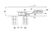
次に、図2を参照して、通常走行における目標経路の生成方法について説明する。図2に示すように、走路境界推定部71は、駐車車両M2〜M6の並びから走路の境界を示す走路境界線L1、L2を推定する。次に、走行空間設定部72は、走路境界線L1と走路境界線L2で挟まれた空間を自車両M1が走行可能な空間として設定する。また、走行空間設定部72は、走行可能空間の車路幅として、走路境界線L1から走路境界線L2までの距離を車路幅Wとして設定する。また、走行空間設定部72は、自車両M1が周囲の物体と接触することなく走行できるように走行可能空間における走路の向きを設定する。   Next, a method for generating a target route in normal travel will be described with reference to FIG. As shown in FIG. 2, the road boundary estimation unit 71 estimates the road boundary lines L1 and L2 indicating the boundary of the road from the arrangement of the parked vehicles M2 to M6. Next, the traveling space setting unit 72 sets a space between the traveling road boundary line L1 and the traveling road boundary line L2 as a space where the host vehicle M1 can travel. Moreover, the traveling space setting unit 72 sets the distance from the traveling road boundary line L1 to the traveling road boundary line L2 as the traveling road width W as the traveling road space width. In addition, the travel space setting unit 72 sets the direction of the travel path in the travelable space so that the host vehicle M1 can travel without coming into contact with surrounding objects.

次に、目標演算部73は、走行空間設定部72によって設定された走路の向きに沿って走行するための目標位置及び目標姿勢を演算する。次に、目標経路生成部77は、GPS受信機10が取得した現在地P1から目標位置まで走行するための目標経路R1を生成する。そして、車両制御部80は、アクチュエータ90を制御して目標経路R1を走行する自律運転を実現する。   Next, the target calculation unit 73 calculates a target position and a target posture for traveling along the direction of the road set by the travel space setting unit 72. Next, the target route generation unit 77 generates a target route R1 for traveling from the current location P1 acquired by the GPS receiver 10 to the target position. And the vehicle control part 80 implement | achieves the autonomous driving | running | working which controls the actuator 90 and drive | works the target path | route R1.

次に、図3A〜図3Cを参照して、通常走行中に駐車枠を検出した場合の処理を説明する。本実施形態では、自車両M1は、駐車枠を探索しながら自律運転を行う。図3Aに示すように、通常走行中に駐車枠検出部74が白線L3と白線L4で挟まれた空間を駐車枠として検出した場合、目標再計算部75は、駐車枠に幅寄せ可能な目標位置及び目標姿勢を再計算する。   Next, with reference to FIGS. 3A to 3C, processing when a parking frame is detected during normal travel will be described. In the present embodiment, the host vehicle M1 performs autonomous driving while searching for a parking frame. As shown in FIG. 3A, when the parking frame detection unit 74 detects a space between the white line L3 and the white line L4 as a parking frame during normal traveling, the target recalculation unit 75 can make the target closer to the parking frame. Recalculate position and target orientation.

具体的には、図3Bに示すように、目標再計算部75は、駐車枠に幅寄せ可能な目標位置P2及び目標姿勢を再計算する。目標位置P2は、駐車枠の手前の走路境界線L2から、自車両M1の車幅方向の中心までの距離が、例えば1.2mになる位置である。また、目標位置P2における目標姿勢は、走行経路の向きに対して平行、あるいはほぼ平行となるような所定の範囲を有する姿勢である。   Specifically, as shown in FIG. 3B, the target recalculation unit 75 recalculates the target position P2 and the target posture that can be brought closer to the parking frame. The target position P2 is a position where the distance from the road boundary line L2 before the parking frame to the center in the vehicle width direction of the host vehicle M1 is 1.2 m, for example. The target posture at the target position P2 is a posture having a predetermined range that is parallel or substantially parallel to the direction of the travel route.

次に変更部76は、目標演算部73によって演算された目標位置及び目標姿勢と、目標再計算部75によって再計算された目標位置P2及び目標姿勢のうち、どちらを優先するかを判断する。判断の基準として、自車両M1が現在地P1から目標位置P2に辿りつくまでに、目標位置P2における目標姿勢が走行経路に対して平行、あるいはほぼ平行となるか否かを基準として設定すればよい。例えば、現在地P1から目標位置P2までの距離が所定距離より長い場合、目標位置P2における目標姿勢が走行経路に対して平行、あるいはほぼ平行となると判断し、現在地P1から目標位置P2までの距離が所定距離より短い場合、目標位置P2における目標姿勢が走行経路に対して平行、あるいはほぼ平行とならないと判断すればよい。なお、判断の基準は、距離の長短に限定されない。目標位置P2における目標姿勢が走行経路に対して整う(平行、あるいはほぼ平行となる)場合、変更部76は、目標演算部73によって演算された目標位置及び目標姿勢を、目標再計算部75によって再計算された目標位置P2及び目標姿勢に変更する。   Next, the changing unit 76 determines which of the target position and target posture calculated by the target calculating unit 73 and the target position P2 and target posture recalculated by the target recalculating unit 75 have priority. As a criterion for determination, it may be set based on whether or not the target posture at the target position P2 is parallel or substantially parallel to the travel route before the host vehicle M1 reaches the target position P2 from the current location P1. . For example, when the distance from the current position P1 to the target position P2 is longer than a predetermined distance, it is determined that the target posture at the target position P2 is parallel or substantially parallel to the travel route, and the distance from the current position P1 to the target position P2 is If the distance is shorter than the predetermined distance, it may be determined that the target posture at the target position P2 is not parallel or substantially parallel to the travel route. Note that the criterion for determination is not limited to the length of the distance. When the target posture at the target position P2 is aligned with the travel route (parallel or substantially parallel), the changing unit 76 uses the target recalculating unit 75 to calculate the target position and target posture calculated by the target calculating unit 73. Change to the recalculated target position P2 and target posture.

一方、目標位置P2における目標姿勢が走行経路に対して整わない(平行、あるいはほぼ平行とならない)場合、変更部76は、目標演算部73によって演算された目標位置及び目標姿勢を継続する。この場合、駐車枠検出部74は、次の駐車枠を探索する。   On the other hand, when the target posture at the target position P2 is not aligned (parallel or substantially parallel) with respect to the travel route, the changing unit 76 continues the target position and target posture calculated by the target calculating unit 73. In this case, the parking frame detection unit 74 searches for the next parking frame.

変更部76が、目標演算部73によって演算された目標位置及び目標姿勢を、目標再計算部75によって再計算された目標位置P2及び目標姿勢に変更した場合、図3Bに示すように、目標経路生成部77は、現在地P1から目標位置P2までの目標経路R2を生成する。車両制御部80は、アクチュエータ90を制御して目標経路R2を走行する自律運転を実現する。次に、図3Cに示すように、目標演算部73は、駐車するための目標位置P3、P4及び目標姿勢を演算し、目標経路生成部77は目標位置P3、P4までの目標経路を生成する。そして、車両制御部80は、アクチュエータ90を制御して自律運転による駐車を完了する。   When the changing unit 76 changes the target position and target posture calculated by the target calculating unit 73 to the target position P2 and target posture recalculated by the target recalculating unit 75, as shown in FIG. The generation unit 77 generates a target route R2 from the current location P1 to the target position P2. The vehicle control unit 80 controls the actuator 90 to realize autonomous driving that travels on the target route R2. Next, as shown in FIG. 3C, the target calculation unit 73 calculates target positions P3 and P4 and a target posture for parking, and the target route generation unit 77 generates a target route to the target positions P3 and P4. . And the vehicle control part 80 controls the actuator 90, and completes the parking by autonomous driving.

次に、図4に示すフローチャートを参照して、走行経路生成装置1の一動作例について説明する。このフローチャートは、例えばイグニッションスイッチがオンされたときに開始する。   Next, an operation example of the travel route generation device 1 will be described with reference to the flowchart shown in FIG. This flowchart is started when, for example, the ignition switch is turned on.

ステップS101において、GPS受信機10や空間認識センサ30などは、各種情報を取得する。   In step S101, the GPS receiver 10, the space recognition sensor 30, and the like acquire various types of information.

ステップS102において、走路境界推定部71は、各種センサの情報を用いて走路の境界を推定する。   In step S102, the road boundary estimation unit 71 estimates the road boundary using information from various sensors.

ステップS103において、走行空間設定部72は、走路境界推定部71によって推定された走路の境界を用いて車両が走行可能な空間を設定する。   In step S <b> 103, the traveling space setting unit 72 sets a space where the vehicle can travel using the boundary of the traveling path estimated by the traveling path boundary estimation unit 71.

ステップS104において、目標演算部73は、走路の向きに沿って走行するための目標位置及び目標姿勢を演算する。   In step S104, the target calculation unit 73 calculates a target position and a target posture for traveling along the direction of the road.

ステップS105において、駐車枠検出部74は、各種センサの情報を用いて車両が駐車可能な駐車枠を検出する。駐車枠検出部74が駐車枠を検出した場合(ステップS106でYes)、処理がステップS107に進む。一方、駐車枠検出部74が駐車枠を検出できない場合(ステップS106でNo)、処理はステップS105に戻る。   In step S105, the parking frame detection unit 74 detects a parking frame in which the vehicle can be parked using information from various sensors. If the parking frame detection unit 74 detects a parking frame (Yes in step S106), the process proceeds to step S107. On the other hand, when the parking frame detection unit 74 cannot detect the parking frame (No in step S106), the process returns to step S105.

ステップS107において、目標再計算部75は、駐車枠に幅寄せ可能な目標位置及び目標姿勢を再計算する。   In step S107, the target recalculation unit 75 recalculates a target position and a target posture that can be shifted to the parking frame.

ステップS108において、変更部76は、目標演算部73によって演算された目標位置及び目標姿勢と、目標再計算部75によって再計算された目標位置及び目標姿勢のうち、どちらを優先するかを判断する。変更部76が目標位置及び目標姿勢を変更する場合(ステップS108でYes)、処理がステップS109に進む。一方、変更部76が目標位置及び目標姿勢を変更しない場合(ステップS108でNo)、処理がステップS110に進む。   In step S <b> 108, the changing unit 76 determines which of the target position and target posture calculated by the target calculating unit 73 and the target position and target posture recalculated by the target recalculating unit 75 has priority. . When the changing unit 76 changes the target position and target posture (Yes in step S108), the process proceeds to step S109. On the other hand, when the changing unit 76 does not change the target position and the target posture (No in step S108), the process proceeds to step S110.

ステップS109において、目標経路生成部77は、駐車するための目標経路を生成する。   In step S109, the target route generation unit 77 generates a target route for parking.

ステップS110において、目標経路生成部77は、通常走行するための目標経路を生成する。   In step S110, the target route generation unit 77 generates a target route for normal travel.

ステップS111において、車両制御部80は、アクチュエータ90を制御して自律運転を実現する。   In step S111, the vehicle control unit 80 controls the actuator 90 to realize autonomous driving.

以上説明したように、本実施形態に係る走行経路生成装置1によれば、以下の作用効果が得られる。   As described above, according to the travel route generation device 1 according to the present embodiment, the following functions and effects can be obtained.

走行経路生成装置1は、自律走行中に駐車枠を検出した場合、駐車枠を検出する前の走行経路における目標位置及び目標姿勢から、駐車枠に幅寄せ可能な目標位置P2及び目標姿勢に変更する。これにより、車路幅Wを有効活用した自律駐車を行うことができる。具体的には、図3Cに示す車路幅Wが狭い場合でも駐車枠に幅寄せすることにより、この車路幅Wを有効活用した自律駐車が可能となる。   When the travel route generation device 1 detects a parking frame during autonomous travel, the travel route generation device 1 changes the target position and target posture on the travel route before detecting the parking frame to a target position P2 and a target posture that can be brought closer to the parking frame. To do. Thereby, the autonomous parking which utilized the road width W effectively can be performed. Specifically, even when the road width W shown in FIG. 3C is narrow, the vehicle can be autonomously parked by effectively using the road width W by bringing the width close to the parking frame.

走行経路生成装置1は、駐車枠を検出した場合に駐車枠に幅寄せ可能な目標位置P2及び目標姿勢を演算する。これにより、事前に駐車枠の情報を取得する必要がなくなり、走行環境に応じた様々な駐車枠での対応が可能となる。   The travel route generation device 1 calculates a target position P2 and a target posture that can be brought closer to the parking frame when the parking frame is detected. Thereby, it becomes unnecessary to acquire information on parking frames in advance, and it is possible to cope with various parking frames according to the traveling environment.

走行経路生成装置1は、駐車枠の手前の位置を駐車枠に幅寄せ可能な目標位置P2として演算する。これにより、走行経路生成装置1は車路幅Wを最大限有効活用でき、様々な車路幅Wにおいて最適かつ最短経路での自律駐車が可能となる。   The travel route generation device 1 calculates the position in front of the parking frame as a target position P2 that can be brought closer to the parking frame. As a result, the travel route generation device 1 can make the most effective use of the road width W, and autonomous parking on the optimum and shortest route is possible in various road widths W.

走行経路生成装置1は、走行経路と平行となるように駐車枠に幅寄せ可能な目標姿勢を演算する。これにより、走行経路生成装置1は車路幅Wを最大限有効活用でき、様々な車路幅Wにおいて最適かつ最短経路での自律駐車が可能となる。   The travel route generation device 1 calculates a target posture that can be brought closer to the parking frame so as to be parallel to the travel route. As a result, the travel route generation device 1 can make the most effective use of the road width W, and autonomous parking on the optimum and shortest route is possible in various road widths W.

走行経路生成装置1は、目標位置P2における目標姿勢が走行経路に対して整わない場合、駐車枠を検出する前の走行経路における目標位置及び目標姿勢を継続し、次の駐車枠を探索する。これにより、駐車枠の検出が遅れ、幅寄せする際の目標姿勢が不十分となる場合には通常走行中の目標位置及び目標姿勢を変更しないため、走行経路生成装置1は通常走行を継続することができる。また、走行経路生成装置1は引き続き駐車枠を探索するため、安全な自律駐車が可能となる。   When the target posture at the target position P2 is not aligned with the travel route, the travel route generation device 1 continues the target position and target posture on the travel route before detecting the parking frame and searches for the next parking frame. As a result, when the detection of the parking frame is delayed and the target posture at the time of width adjustment becomes insufficient, the target position and the target posture during the normal travel are not changed, so the travel route generation device 1 continues the normal travel. be able to. In addition, since the travel route generation device 1 continues to search for a parking frame, safe autonomous parking is possible.

上記のように、本発明の実施形態を記載したが、この開示の一部をなす論述及び図面はこの発明を限定するものであると理解すべきではない。この開示から当業者には様々な代替実施の形態、実施例及び運用技術が明らかとなろう。   Although the embodiments of the present invention have been described as described above, it should not be understood that the descriptions and drawings constituting a part of this disclosure limit the present invention. From this disclosure, various alternative embodiments, examples and operational techniques will be apparent to those skilled in the art.

本実施形態において、走路境界推定部71は、ポイントクラウド情報を用いて走路の境界を推定したが、これに限られない。例えば、走路境界推定部71は、車両に設置されたカメラの画像から車線境界線や車道外側線等の路面に描かれた区画線を検出し、走路の境界を推定してもよい。   In this embodiment, the road boundary estimation part 71 estimated the boundary of the road using point cloud information, but it is not restricted to this. For example, the runway boundary estimation unit 71 may detect a demarcation line drawn on a road surface such as a lane boundary line or a roadway outer line from an image of a camera installed on the vehicle, and may estimate the road boundary.

また、駐車枠検出部74は、レーザーレーダの情報を用いて駐車枠を検出したが、これに限られない。例えば、駐車枠検出部74は、地図情報や交通インフラストラクチャ情報を用いて駐車枠を検出してもよい。これにより、駐車枠検出部74はより早く駐車枠を検出でき、目標再計算部75はより早く駐車枠に幅寄せ可能な目標位置及び目標姿勢を再計算できる。これにより、よりスムーズな幅寄せが可能となる。   Moreover, although the parking frame detection part 74 detected the parking frame using the information of a laser radar, it is not restricted to this. For example, the parking frame detection unit 74 may detect a parking frame using map information and traffic infrastructure information. Thereby, the parking frame detection part 74 can detect a parking frame earlier, and the target recalculation part 75 can recalculate the target position and target attitude | position which can be brought closer to a parking frame earlier. Thereby, smoother width alignment becomes possible.

なお、上述の実施形態の各機能は、1または複数の処理回路により実装され得る。処理回路は、電気回路を含む処理装置等のプログラムされた処理装置を含む。処理回路は、また、実施形態に記載された機能を実行するようにアレンジされた特定用途向け集積回路(ASIC)や従来型の回路部品のような装置を含む。   Note that each function of the above-described embodiment may be implemented by one or a plurality of processing circuits. The processing circuit includes a programmed processing device such as a processing device including an electrical circuit. The processing circuitry also includes devices such as application specific integrated circuits (ASICs) and conventional circuit components arranged to perform the functions described in the embodiments.

1 走行経路生成装置
10 GPS受信機
20 地図データベース
30 空間認識センサ
40 操舵角センサ
50 車輪速センサ
60 車両状態量センサ
70 コントローラ
71 走路境界推定部
72 走行空間設定部
73 目標演算部
74 駐車枠検出部
75 目標再計算部
76 変更部
77 目標経路生成部
80 車両制御部
90 アクチュエータ
DESCRIPTION OF SYMBOLS 1 Travel route production | generation apparatus 10 GPS receiver 20 Map database 30 Space recognition sensor 40 Steering angle sensor 50 Wheel speed sensor 60 Vehicle state quantity sensor 70 Controller 71 Travel path boundary estimation part 72 Travel space setting part 73 Target calculation part 74 Parking frame detection part 75 Target recalculation unit 76 Change unit 77 Target route generation unit 80 Vehicle control unit 90 Actuator

Claims (7)

自車両の周囲の物体を検出し、駐車枠を探索しながら自律走行する自律運転車両に用いる走行経路生成方法であって、
前記駐車枠を検出したとき、前記駐車枠を検出する前の走行経路における目標位置及び目標姿勢と異なる、前記駐車枠に幅寄せ可能な目標位置及び目標姿勢に変更することを特徴とする走行経路生成方法。
A traveling route generation method used for an autonomous driving vehicle that detects an object around the host vehicle and autonomously travels while searching for a parking frame,
When the parking frame is detected, the travel route is changed to a target position and a target posture that are different from a target position and a target posture in the travel route before the parking frame is detected, and can be brought closer to the parking frame. Generation method.
前記駐車枠を検出したとき、前記駐車枠に幅寄せ可能な目標位置及び目標姿勢を演算することを特徴とする請求項1に記載の走行経路生成方法。   2. The travel route generation method according to claim 1, wherein when the parking frame is detected, a target position and a target posture that can be brought closer to the parking frame are calculated. 前記駐車枠の手前の位置を、前記駐車枠に幅寄せ可能な目標位置として演算することを特徴とする請求項2に記載の走行経路生成方法。   The travel route generation method according to claim 2, wherein a position in front of the parking frame is calculated as a target position that can be brought closer to the parking frame. 前記走行経路と平行となるように前記駐車枠に幅寄せ可能な目標姿勢を演算することを特徴とする請求項2または3に記載の走行経路生成方法。   The travel route generation method according to claim 2 or 3, wherein a target posture that can be brought closer to the parking frame so as to be parallel to the travel route is calculated. レーザーレーダ、地図情報及び交通インフラストラクチャ情報のうちの少なくとも一つを用いて前記駐車枠を検出することを特徴とする請求項1〜4のいずれか1項に記載の走行経路生成方法。   The travel route generation method according to any one of claims 1 to 4, wherein the parking frame is detected using at least one of laser radar, map information, and traffic infrastructure information. 前記駐車枠に幅寄せ可能な目標位置における目標姿勢が整わない場合、前記駐車枠を検出する前の走行経路における目標位置及び目標姿勢を継続し、次の駐車枠を探索することを特徴とする請求項1〜5のいずれか1項に記載の走行経路生成方法。   When the target posture at the target position that can be brought close to the parking frame is not aligned, the target position and the target posture on the travel route before detecting the parking frame are continued, and the next parking frame is searched. The travel route generation method according to any one of claims 1 to 5. 自車両の周囲の物体を検出するセンサと、
前記センサによって検出された前記周囲の物体に基づいて、自律走行を制御するコントローラと、を備え、
前記コントローラは、前記センサによって駐車枠が検出されたとき、前記駐車枠を検出する前の走行経路における目標位置及び目標姿勢と異なる、前記駐車枠に幅寄せ可能な目標位置及び目標姿勢に変更することを特徴とする走行経路生成装置。


A sensor that detects objects around the vehicle,
A controller that controls autonomous running based on the surrounding objects detected by the sensor, and
When the parking frame is detected by the sensor, the controller changes to a target position and a target posture that are different from a target position and a target posture on the travel route before the parking frame is detected and can be brought closer to the parking frame. A travel route generation device characterized by that.


JP2016119705A 2016-06-16 2016-06-16 Travel route generation method and travel route generation device Active JP6673043B2 (en)

Priority Applications (1)

Application Number Priority Date Filing Date Title
JP2016119705A JP6673043B2 (en) 2016-06-16 2016-06-16 Travel route generation method and travel route generation device

Applications Claiming Priority (1)

Application Number Priority Date Filing Date Title
JP2016119705A JP6673043B2 (en) 2016-06-16 2016-06-16 Travel route generation method and travel route generation device

Publications (2)

Publication Number Publication Date
JP2017222279A true JP2017222279A (en) 2017-12-21
JP6673043B2 JP6673043B2 (en) 2020-03-25

Family

ID=60686250

Family Applications (1)

Application Number Title Priority Date Filing Date
JP2016119705A Active JP6673043B2 (en) 2016-06-16 2016-06-16 Travel route generation method and travel route generation device

Country Status (1)

Country Link
JP (1) JP6673043B2 (en)

Citations (4)

* Cited by examiner, † Cited by third party
Publication number Priority date Publication date Assignee Title
JP2008179345A (en) * 2006-12-26 2008-08-07 Honda Motor Co Ltd Automatic parking control apparatus for vehicle
JP2010208392A (en) * 2009-03-09 2010-09-24 Nissan Motor Co Ltd Parking support device and parking support method
JP2010269707A (en) * 2009-05-21 2010-12-02 Honda Motor Co Ltd Parking assist system of vehicle
WO2015137012A1 (en) * 2014-03-12 2015-09-17 日産自動車株式会社 Vehicle operation device

Patent Citations (4)

* Cited by examiner, † Cited by third party
Publication number Priority date Publication date Assignee Title
JP2008179345A (en) * 2006-12-26 2008-08-07 Honda Motor Co Ltd Automatic parking control apparatus for vehicle
JP2010208392A (en) * 2009-03-09 2010-09-24 Nissan Motor Co Ltd Parking support device and parking support method
JP2010269707A (en) * 2009-05-21 2010-12-02 Honda Motor Co Ltd Parking assist system of vehicle
WO2015137012A1 (en) * 2014-03-12 2015-09-17 日産自動車株式会社 Vehicle operation device

Also Published As

Publication number Publication date
JP6673043B2 (en) 2020-03-25

Similar Documents

Publication Publication Date Title
US10310508B2 (en) Vehicle control apparatus
US9896101B2 (en) Autonomous driving vehicle system
CN108292475B (en) Method and device for generating predicted vehicle information used for traveling of vehicle road network
US20170227970A1 (en) Autonomous driving system
US10988139B2 (en) Vehicle position control method and device vehicle position control device for correcting position in drive-assisted vehicle
CN109195860B (en) Lane curb assisted off-lane check and lane keeping system for autonomous vehicles
US9911330B2 (en) Driving assistance device and driving assistance method
US10048699B2 (en) Vehicle control apparatus
JP6705414B2 (en) Operating range determination device
EP3655298B1 (en) A tunnel-based planning system for autonomous driving vehicles
US11338803B2 (en) Traveling track determination processing and automated drive device
RU2735720C1 (en) Method of estimating a vehicle, a method for correcting a route, a vehicle evaluation device and a route correction device
JP2019045379A (en) Own vehicle position estimation device
JP2017151764A (en) Travelling control device
JP6665929B2 (en) Parking assistance method and device
JP2017047798A (en) Travel control device of vehicle
JPWO2016189649A1 (en) Stop position setting apparatus and method
KR102057428B1 (en) Driving control method and driving control device of vehicle
JP6297956B2 (en) Route generator
JP2020005401A (en) Control device of automatic operation vehicle
JP2018180641A (en) Vehicle identification device
JP6848531B2 (en) Target position estimation method and target position estimation device
JP6673043B2 (en) Travel route generation method and travel route generation device
US20210303874A1 (en) A point cloud-based low-height obstacle detection system
JP7123994B2 (en) vehicle control system

Legal Events

Date Code Title Description
A621 Written request for application examination

Free format text: JAPANESE INTERMEDIATE CODE: A621

Effective date: 20190328

A131 Notification of reasons for refusal

Free format text: JAPANESE INTERMEDIATE CODE: A131

Effective date: 20191126

A977 Report on retrieval

Free format text: JAPANESE INTERMEDIATE CODE: A971007

Effective date: 20191128

A521 Request for written amendment filed

Free format text: JAPANESE INTERMEDIATE CODE: A523

Effective date: 20200121

TRDD Decision of grant or rejection written
A01 Written decision to grant a patent or to grant a registration (utility model)

Free format text: JAPANESE INTERMEDIATE CODE: A01

Effective date: 20200204

A61 First payment of annual fees (during grant procedure)

Free format text: JAPANESE INTERMEDIATE CODE: A61

Effective date: 20200217

R151 Written notification of patent or utility model registration

Ref document number: 6673043

Country of ref document: JP

Free format text: JAPANESE INTERMEDIATE CODE: R151