JP2017222000A - Bonding method - Google Patents
Bonding method Download PDFInfo
- Publication number
- JP2017222000A JP2017222000A JP2016119077A JP2016119077A JP2017222000A JP 2017222000 A JP2017222000 A JP 2017222000A JP 2016119077 A JP2016119077 A JP 2016119077A JP 2016119077 A JP2016119077 A JP 2016119077A JP 2017222000 A JP2017222000 A JP 2017222000A
- Authority
- JP
- Japan
- Prior art keywords
- joining
- flange
- expansion
- insertion portion
- bonding
- Prior art date
- Legal status (The legal status is an assumption and is not a legal conclusion. Google has not performed a legal analysis and makes no representation as to the accuracy of the status listed.)
- Granted
Links
- 238000000034 method Methods 0.000 title claims abstract description 113
- 238000003780 insertion Methods 0.000 claims abstract description 99
- 230000037431 insertion Effects 0.000 claims abstract description 99
- 238000010438 heat treatment Methods 0.000 claims abstract description 73
- 230000001105 regulatory effect Effects 0.000 claims abstract description 72
- 238000001816 cooling Methods 0.000 claims abstract description 25
- 238000009434 installation Methods 0.000 claims description 30
- 238000012545 processing Methods 0.000 abstract description 8
- 230000033228 biological regulation Effects 0.000 abstract description 6
- 238000010586 diagram Methods 0.000 description 38
- 239000000463 material Substances 0.000 description 25
- 230000000052 comparative effect Effects 0.000 description 18
- 230000005674 electromagnetic induction Effects 0.000 description 13
- 230000002093 peripheral effect Effects 0.000 description 13
- 230000000694 effects Effects 0.000 description 8
- 238000012986 modification Methods 0.000 description 8
- 230000004048 modification Effects 0.000 description 8
- 230000006698 induction Effects 0.000 description 5
- 230000007423 decrease Effects 0.000 description 4
- 230000008602 contraction Effects 0.000 description 3
- 229910000838 Al alloy Inorganic materials 0.000 description 2
- 229910001069 Ti alloy Inorganic materials 0.000 description 2
- 238000011156 evaluation Methods 0.000 description 2
- 239000000203 mixture Substances 0.000 description 2
- 230000003252 repetitive effect Effects 0.000 description 2
- 238000005516 engineering process Methods 0.000 description 1
- 238000007689 inspection Methods 0.000 description 1
- 238000011900 installation process Methods 0.000 description 1
- 229910000833 kovar Inorganic materials 0.000 description 1
- 238000005259 measurement Methods 0.000 description 1
- 239000000523 sample Substances 0.000 description 1
- 238000009210 therapy by ultrasound Methods 0.000 description 1
Images


Classifications
-
- B—PERFORMING OPERATIONS; TRANSPORTING
- B29—WORKING OF PLASTICS; WORKING OF SUBSTANCES IN A PLASTIC STATE IN GENERAL
- B29C—SHAPING OR JOINING OF PLASTICS; SHAPING OF MATERIAL IN A PLASTIC STATE, NOT OTHERWISE PROVIDED FOR; AFTER-TREATMENT OF THE SHAPED PRODUCTS, e.g. REPAIRING
- B29C66/00—General aspects of processes or apparatus for joining preformed parts
- B29C66/90—Measuring or controlling the joining process
- B29C66/91—Measuring or controlling the joining process by measuring or controlling the temperature, the heat or the thermal flux
- B29C66/919—Measuring or controlling the joining process by measuring or controlling the temperature, the heat or the thermal flux characterised by specific temperature, heat or thermal flux values or ranges
-
- B—PERFORMING OPERATIONS; TRANSPORTING
- B23—MACHINE TOOLS; METAL-WORKING NOT OTHERWISE PROVIDED FOR
- B23P—METAL-WORKING NOT OTHERWISE PROVIDED FOR; COMBINED OPERATIONS; UNIVERSAL MACHINE TOOLS
- B23P11/00—Connecting or disconnecting metal parts or objects by metal-working techniques not otherwise provided for
- B23P11/02—Connecting or disconnecting metal parts or objects by metal-working techniques not otherwise provided for by first expanding and then shrinking or vice versa, e.g. by using pressure fluids; by making force fits
- B23P11/025—Connecting or disconnecting metal parts or objects by metal-working techniques not otherwise provided for by first expanding and then shrinking or vice versa, e.g. by using pressure fluids; by making force fits by using heat or cold
-
- A—HUMAN NECESSITIES
- A61—MEDICAL OR VETERINARY SCIENCE; HYGIENE
- A61N—ELECTROTHERAPY; MAGNETOTHERAPY; RADIATION THERAPY; ULTRASOUND THERAPY
- A61N7/00—Ultrasound therapy
-
- B—PERFORMING OPERATIONS; TRANSPORTING
- B23—MACHINE TOOLS; METAL-WORKING NOT OTHERWISE PROVIDED FOR
- B23P—METAL-WORKING NOT OTHERWISE PROVIDED FOR; COMBINED OPERATIONS; UNIVERSAL MACHINE TOOLS
- B23P11/00—Connecting or disconnecting metal parts or objects by metal-working techniques not otherwise provided for
- B23P11/02—Connecting or disconnecting metal parts or objects by metal-working techniques not otherwise provided for by first expanding and then shrinking or vice versa, e.g. by using pressure fluids; by making force fits
-
- B—PERFORMING OPERATIONS; TRANSPORTING
- B29—WORKING OF PLASTICS; WORKING OF SUBSTANCES IN A PLASTIC STATE IN GENERAL
- B29C—SHAPING OR JOINING OF PLASTICS; SHAPING OF MATERIAL IN A PLASTIC STATE, NOT OTHERWISE PROVIDED FOR; AFTER-TREATMENT OF THE SHAPED PRODUCTS, e.g. REPAIRING
- B29C66/00—General aspects of processes or apparatus for joining preformed parts
- B29C66/40—General aspects of joining substantially flat articles, e.g. plates, sheets or web-like materials; Making flat seams in tubular or hollow articles; Joining single elements to substantially flat surfaces
- B29C66/41—Joining substantially flat articles ; Making flat seams in tubular or hollow articles
-
- B—PERFORMING OPERATIONS; TRANSPORTING
- B29—WORKING OF PLASTICS; WORKING OF SUBSTANCES IN A PLASTIC STATE IN GENERAL
- B29C—SHAPING OR JOINING OF PLASTICS; SHAPING OF MATERIAL IN A PLASTIC STATE, NOT OTHERWISE PROVIDED FOR; AFTER-TREATMENT OF THE SHAPED PRODUCTS, e.g. REPAIRING
- B29C66/00—General aspects of processes or apparatus for joining preformed parts
- B29C66/70—General aspects of processes or apparatus for joining preformed parts characterised by the composition, physical properties or the structure of the material of the parts to be joined; Joining with non-plastics material
- B29C66/71—General aspects of processes or apparatus for joining preformed parts characterised by the composition, physical properties or the structure of the material of the parts to be joined; Joining with non-plastics material characterised by the composition of the plastics material of the parts to be joined
-
- B—PERFORMING OPERATIONS; TRANSPORTING
- B29—WORKING OF PLASTICS; WORKING OF SUBSTANCES IN A PLASTIC STATE IN GENERAL
- B29C—SHAPING OR JOINING OF PLASTICS; SHAPING OF MATERIAL IN A PLASTIC STATE, NOT OTHERWISE PROVIDED FOR; AFTER-TREATMENT OF THE SHAPED PRODUCTS, e.g. REPAIRING
- B29C66/00—General aspects of processes or apparatus for joining preformed parts
- B29C66/70—General aspects of processes or apparatus for joining preformed parts characterised by the composition, physical properties or the structure of the material of the parts to be joined; Joining with non-plastics material
- B29C66/73—General aspects of processes or apparatus for joining preformed parts characterised by the composition, physical properties or the structure of the material of the parts to be joined; Joining with non-plastics material characterised by the intensive physical properties of the material of the parts to be joined, by the optical properties of the material of the parts to be joined, by the extensive physical properties of the parts to be joined, by the state of the material of the parts to be joined or by the material of the parts to be joined being a thermoplastic or a thermoset
- B29C66/731—General aspects of processes or apparatus for joining preformed parts characterised by the composition, physical properties or the structure of the material of the parts to be joined; Joining with non-plastics material characterised by the intensive physical properties of the material of the parts to be joined, by the optical properties of the material of the parts to be joined, by the extensive physical properties of the parts to be joined, by the state of the material of the parts to be joined or by the material of the parts to be joined being a thermoplastic or a thermoset characterised by the intensive physical properties of the material of the parts to be joined
- B29C66/7311—Thermal properties
- B29C66/73115—Melting point
- B29C66/73116—Melting point of different melting point, i.e. the melting point of one of the parts to be joined being different from the melting point of the other part
-
- B—PERFORMING OPERATIONS; TRANSPORTING
- B29—WORKING OF PLASTICS; WORKING OF SUBSTANCES IN A PLASTIC STATE IN GENERAL
- B29C—SHAPING OR JOINING OF PLASTICS; SHAPING OF MATERIAL IN A PLASTIC STATE, NOT OTHERWISE PROVIDED FOR; AFTER-TREATMENT OF THE SHAPED PRODUCTS, e.g. REPAIRING
- B29C66/00—General aspects of processes or apparatus for joining preformed parts
- B29C66/70—General aspects of processes or apparatus for joining preformed parts characterised by the composition, physical properties or the structure of the material of the parts to be joined; Joining with non-plastics material
- B29C66/74—Joining plastics material to non-plastics material
- B29C66/742—Joining plastics material to non-plastics material to metals or their alloys
-
- B—PERFORMING OPERATIONS; TRANSPORTING
- B29—WORKING OF PLASTICS; WORKING OF SUBSTANCES IN A PLASTIC STATE IN GENERAL
- B29C—SHAPING OR JOINING OF PLASTICS; SHAPING OF MATERIAL IN A PLASTIC STATE, NOT OTHERWISE PROVIDED FOR; AFTER-TREATMENT OF THE SHAPED PRODUCTS, e.g. REPAIRING
- B29C66/00—General aspects of processes or apparatus for joining preformed parts
- B29C66/80—General aspects of machine operations or constructions and parts thereof
- B29C66/83—General aspects of machine operations or constructions and parts thereof characterised by the movement of the joining or pressing tools
- B29C66/832—Reciprocating joining or pressing tools
- B29C66/8322—Joining or pressing tools reciprocating along one axis
-
- B—PERFORMING OPERATIONS; TRANSPORTING
- B29—WORKING OF PLASTICS; WORKING OF SUBSTANCES IN A PLASTIC STATE IN GENERAL
- B29C—SHAPING OR JOINING OF PLASTICS; SHAPING OF MATERIAL IN A PLASTIC STATE, NOT OTHERWISE PROVIDED FOR; AFTER-TREATMENT OF THE SHAPED PRODUCTS, e.g. REPAIRING
- B29C66/00—General aspects of processes or apparatus for joining preformed parts
- B29C66/90—Measuring or controlling the joining process
- B29C66/91—Measuring or controlling the joining process by measuring or controlling the temperature, the heat or the thermal flux
- B29C66/914—Measuring or controlling the joining process by measuring or controlling the temperature, the heat or the thermal flux by controlling or regulating the temperature, the heat or the thermal flux
- B29C66/9141—Measuring or controlling the joining process by measuring or controlling the temperature, the heat or the thermal flux by controlling or regulating the temperature, the heat or the thermal flux by controlling or regulating the temperature
- B29C66/91411—Measuring or controlling the joining process by measuring or controlling the temperature, the heat or the thermal flux by controlling or regulating the temperature, the heat or the thermal flux by controlling or regulating the temperature of the parts to be joined, e.g. the joining process taking the temperature of the parts to be joined into account
-
- B—PERFORMING OPERATIONS; TRANSPORTING
- B29—WORKING OF PLASTICS; WORKING OF SUBSTANCES IN A PLASTIC STATE IN GENERAL
- B29C—SHAPING OR JOINING OF PLASTICS; SHAPING OF MATERIAL IN A PLASTIC STATE, NOT OTHERWISE PROVIDED FOR; AFTER-TREATMENT OF THE SHAPED PRODUCTS, e.g. REPAIRING
- B29C66/00—General aspects of processes or apparatus for joining preformed parts
- B29C66/90—Measuring or controlling the joining process
- B29C66/91—Measuring or controlling the joining process by measuring or controlling the temperature, the heat or the thermal flux
- B29C66/914—Measuring or controlling the joining process by measuring or controlling the temperature, the heat or the thermal flux by controlling or regulating the temperature, the heat or the thermal flux
- B29C66/9141—Measuring or controlling the joining process by measuring or controlling the temperature, the heat or the thermal flux by controlling or regulating the temperature, the heat or the thermal flux by controlling or regulating the temperature
- B29C66/91441—Measuring or controlling the joining process by measuring or controlling the temperature, the heat or the thermal flux by controlling or regulating the temperature, the heat or the thermal flux by controlling or regulating the temperature the temperature being non-constant over time
- B29C66/91443—Measuring or controlling the joining process by measuring or controlling the temperature, the heat or the thermal flux by controlling or regulating the temperature, the heat or the thermal flux by controlling or regulating the temperature the temperature being non-constant over time following a temperature-time profile
-
- F—MECHANICAL ENGINEERING; LIGHTING; HEATING; WEAPONS; BLASTING
- F16—ENGINEERING ELEMENTS AND UNITS; GENERAL MEASURES FOR PRODUCING AND MAINTAINING EFFECTIVE FUNCTIONING OF MACHINES OR INSTALLATIONS; THERMAL INSULATION IN GENERAL
- F16B—DEVICES FOR FASTENING OR SECURING CONSTRUCTIONAL ELEMENTS OR MACHINE PARTS TOGETHER, e.g. NAILS, BOLTS, CIRCLIPS, CLAMPS, CLIPS OR WEDGES; JOINTS OR JOINTING
- F16B4/00—Shrinkage connections, e.g. assembled with the parts at different temperature; Force fits; Non-releasable friction-grip fastenings
- F16B4/006—Shrinkage connections, e.g. assembled with the parts being at different temperature
- F16B4/008—Shrinkage connections, e.g. assembled with the parts being at different temperature using heat-recoverable, i.e. shrinkable, sleeves
Abstract
Description
本発明は、焼き嵌めにより2つの接合対象を互いに接合する接合方法に関する。 The present invention relates to a joining method for joining two joining objects together by shrink fitting.
従来、第1部材と、当該第1部材が挿入される接合用挿入部を有する第2部材との2つの接合対象を互いに接合する接合方法として、焼き嵌めが知られている(例えば、特許文献1参照)。
焼き嵌めは、第2部材を予め加熱して熱膨張させることにより接合用挿入部を拡径させ、その拡径状態の時に第1部材を挿入し、冷却時の接合用挿入部の縮径を利用して両者を接合させる技術である。
特許文献1に記載の技術では、接合対象同士の接合強度を向上させるために、当該接合対象の接合面に粗面領域を設けて上述した焼き嵌めを行っている。
Conventionally, shrink fitting is known as a joining method for joining two joining objects of a first member and a second member having a joining insertion portion into which the first member is inserted (for example, Patent Literature 1). 1).
In shrink fitting, the second member is preheated and thermally expanded to expand the diameter of the joining insert, the first member is inserted in the expanded state, and the diameter of the joining insert is reduced during cooling. It is a technology that joins them together.
In the technique described in
ところで、所望の接合強度を得るためには、できるだけ大きな締め代を確保する必要がある。なお、締め代は、以下に示す式で定義される。以下の外径寸法及び内径寸法は、室温時の寸法である。
〔締め代〕=〔第1部材の外径寸法〕−〔接合用挿入部の内径寸法〕
また、接合用挿入部の内径寸法が小さいと、加熱時の第2部材の熱膨張による当該接合用挿入部の拡径量が小さくなる。このため、所望の接合強度を得るための締め代の上限値も小さくなる(締め代の範囲が狭くなる)。
特許文献1に記載の技術においても、接合用挿入部の内径寸法が小さいと、所望の接合強度を得るための締め代の範囲は狭くなる。このため、第1部材の外径寸法と接合用挿入部の内径寸法との加工公差を狭い範囲で管理する必要がある。すなわち、接合対象に対して全数検査等を実施して精度を保障する必要があり、コストアップの要因となる。
このため、接合対象の加工管理を容易にしつつ、所望の接合強度を得ることができる技術が要望されている。
By the way, in order to obtain a desired bonding strength, it is necessary to secure as large an allowance as possible. The tightening allowance is defined by the following formula. The following outer diameter dimensions and inner diameter dimensions are dimensions at room temperature.
[Tightening allowance] = [Outer diameter dimension of the first member] − [Inner diameter dimension of the insertion portion for joining]
Further, when the inner diameter dimension of the joining insertion portion is small, the diameter expansion amount of the joining insertion portion due to thermal expansion of the second member during heating is reduced. For this reason, the upper limit value of the tightening allowance for obtaining a desired joint strength is also reduced (the tightening allowance range is narrowed).
Also in the technique described in
For this reason, the technique which can obtain desired joining strength is desired, making processing management of the joining object easy.
本発明は、上記に鑑みてなされたものであって、接合対象の加工管理を容易にしつつ、所望の接合強度を得ることができる接合方法を提供することを目的とする。 This invention is made | formed in view of the above, Comprising: It aims at providing the joining method which can obtain desired joining strength, making the process management of joining object easy.
上述した課題を解決し、目的を達成するために、本発明に係る接合方法は、第1部材と、当該第1部材が挿入される接合用挿入部を有する第2部材との2つの接合対象を互いに接合する接合方法であって、膨張規制部材内に設置され、前記接合用挿入部に前記第1部材が挿入された前記第2部材を第1温度まで加熱し、当該第2部材の熱膨張を前記膨張規制部材の内面にて機械的に規制して前記接合用挿入部を縮径する方向に塑性変形させる追加加熱工程と、前記追加加熱工程の後、前記第2部材を冷却して、前記第1部材と前記第2部材とを互いに接合する冷却工程とを備える。 In order to solve the above-described problems and achieve the object, the joining method according to the present invention includes two joining objects: a first member and a second member having a joining insertion portion into which the first member is inserted. The second member, which is installed in an expansion regulating member and the first member is inserted into the joining insertion portion, is heated to a first temperature, and heat of the second member is obtained. An additional heating step of mechanically regulating expansion at the inner surface of the expansion regulating member and plastically deforming the joining insertion portion in a direction of reducing the diameter, and after the additional heating step, cooling the second member And a cooling step of joining the first member and the second member to each other.
また、本発明に係る接合方法では、上記発明において、前記膨張規制部材は、前記第2部材が挿入される設置用挿入部を有し、前記追加加熱工程の際、当該設置用挿入部の内面にて前記第2部材の熱膨張を機械的に規制し、当該接合方法は、前記設置用挿入部と前記第2部材の外面との間に隙間を有した状態で、当該設置用挿入部に前記第2部材を挿入する第2部材設置工程と、前記第2部材設置工程の後、前記第2部材を前記第1温度よりも低い第2温度まで加熱し、当該第2部材を熱膨張させる接合前加熱工程と、前記接合前加熱工程の際、当該接合前加熱工程の後、または前記追加加熱工程の際に実施され、前記接合用挿入部に前記第1部材を挿入する第1部材挿入工程とを備え、前記追加加熱工程は、前記接合前加熱工程の後に実施されることを特徴とする。 Moreover, in the joining method according to the present invention, in the above invention, the expansion regulating member has an installation insertion part into which the second member is inserted, and an inner surface of the installation insertion part during the additional heating step. And mechanically restricting the thermal expansion of the second member, and the joining method is performed on the installation insertion portion with a gap between the installation insertion portion and the outer surface of the second member. After the second member installation step of inserting the second member and the second member installation step, the second member is heated to a second temperature lower than the first temperature to thermally expand the second member. First member insertion that is performed during the pre-bonding heating step and the pre-bonding heating step, after the pre-bonding heating step, or during the additional heating step, and inserting the first member into the bonding insertion portion. And the additional heating step is carried out after the pre-bonding heating step. Characterized in that it is.
また、本発明に係る接合方法では、上記発明において、前記追加加熱工程及び前記冷却工程は、前記第2部材の熱膨張に対する機械的な規制が強い前記膨張規制部材に順次、変更されながら、複数回、繰り返し実施されることを特徴とする。 Further, in the joining method according to the present invention, in the above invention, the additional heating step and the cooling step are sequentially changed to the expansion restricting member having a strong mechanical restriction on the thermal expansion of the second member. It is characterized by being repeatedly performed.
また、本発明に係る接合方法では、上記発明において、前記膨張規制部材は、前記第2部材が挿入される設置用挿入部を有し、前記追加加熱工程の際、当該設置用挿入部の内面にて前記第2部材の熱膨張を機械的に規制し、前記追加加熱工程及び前記冷却工程は、前記設置用挿入部の内径寸法が小さい前記膨張規制部材に順次、変更されながら、複数回、繰り返し実施されることを特徴とする。 Moreover, in the joining method according to the present invention, in the above invention, the expansion regulating member has an installation insertion part into which the second member is inserted, and an inner surface of the installation insertion part during the additional heating step. The second member is mechanically restricted in thermal expansion, and the additional heating step and the cooling step are sequentially changed to the expansion restricting member having a smaller inner diameter of the installation insertion portion, a plurality of times, It is repeatedly performed.
また、本発明に係る接合方法では、上記発明において、前記膨張規制部材の線膨張係数は、前記第2部材の線膨張係数よりも小さいことを特徴とする。 Further, in the joining method according to the present invention, in the above invention, the linear expansion coefficient of the expansion regulating member is smaller than the linear expansion coefficient of the second member.
本発明に係る接合方法によれば、接合対象の加工管理を容易にしつつ、所望の接合強度を得ることができる、という効果を奏する。 According to the joining method according to the present invention, there is an effect that desired joining strength can be obtained while facilitating processing management of joining objects.
以下に、図面を参照して、本発明を実施するための形態(以下、実施の形態)について説明する。なお、以下に説明する実施の形態によって本発明が限定されるものではない。さらに、図面の記載において、同一の部分には同一の符号を付している。 DESCRIPTION OF EMBODIMENTS Hereinafter, modes for carrying out the present invention (hereinafter, embodiments) will be described with reference to the drawings. The present invention is not limited to the embodiments described below. Furthermore, the same code | symbol is attached | subjected to the same part in description of drawing.
(実施の形態1)
〔接合対象の構成〕
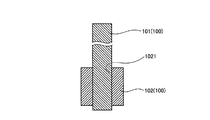
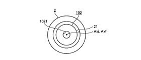
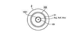
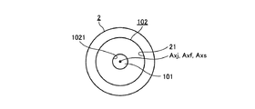
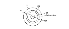
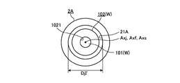
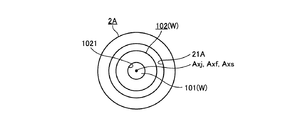
図1及び図2は、本発明の実施の形態1に係る2つの接合対象100を示す図である。具体的に、図1は、2つの接合対象100の斜視図である。図2は、2つの接合対象100を当該2つの接合対象100の中心軸に沿う切断面にて切断した断面図である。なお、図1及び図2では、説明の便宜上、接合対象100同士が互いに接合された状態を示している。
2つの接合対象100は、図1または図2に示すように、軸部材101と、フランジ102とで構成される。
(Embodiment 1)
[Composition of joining objects]
1 and 2 are diagrams showing two joining
As shown in FIG. 1 or FIG. 2, the two joining
軸部材101は、本発明に係る第1部材に相当し、図1または図2に示すように、長尺状の略円柱部材で構成されている。そして、軸部材101は、例えば、チタン合金等で構成されている。
フランジ102は、本発明に係る第2部材に相当し、図1または図2に示すように、第1部材101が挿入される接合用挿入部1021(図1,図2)を有する略円筒状に形成されている。そして、フランジ102は、例えば、アルミ合金(線膨張係数α:約25×10−6/℃)等で構成されている。
The
The
以上説明した軸部材101及びフランジ102は、図1または図2に示すように、接合用挿入部1021に軸部材101が挿入された状態で互いに接合される。
そして、互いに接合された軸部材101及びフランジ102は、例えば、超音波エネルギを生体組織に付与して当該生体組織を処置する超音波処置具に用いられる。具体的に、互いに接合された軸部材101及びフランジ102は、超音波振動子が発生した超音波振動を一端(図1,図2中、下方側の端部)から当該生体組織に接触する他端(図1,図2中、上方側の端部)に伝達するプローブとして用いられる。
The
The
〔接合装置の構成〕
次に、接合対象100同士を接合する接合装置1の構成について説明する。
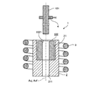
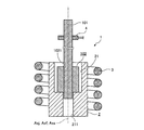
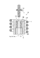
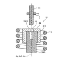
図3A及び図3Bは、接合装置1を示す図である。具体的に、図3Aは、接合装置1を側方から見た断面図である。図3Bは、接合装置1の上面図である。なお、図3Bでは、説明の便宜上、電磁誘導加熱コイル3及び軸部材把持部4の図示を省略している。
接合装置1は、図3Aまたは図3Bに示すように、第1膨張規制部材2と、電磁誘導加熱コイル3(図3A)と、軸部材把持部4(図3A)とを備える。
[Composition of joining equipment]
Next, the structure of the joining
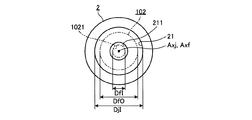
3A and 3B are diagrams showing the
As shown in FIG. 3A or 3B, the joining
第1膨張規制部材2は、本発明に係る膨張規制部材に相当し、図3Aまたは図3Bに示すように、鉛直軸に沿って延在する円柱部材で構成されている。そして、第1膨張規制部材2は、例えば、コバール(線膨張係数β:約5×10⁻⁶/℃)等で構成されている。すなわち、第1膨張規制部材2は、その線膨張係数βが第2部材102の線膨張係数αよりも小さい材料で構成されている。
この第1膨張規制部材2において、上端部には、図3Aまたは図3Bに示すように、下端部に向けて窪む平面視円形状の凹部21が形成されている。この凹部21の内径寸法DjIは、室温時において、フランジ102の外径寸法DfOよりも大きく設定されている。また、凹部21の高さ寸法(第1膨張規制部材2の中心軸Axjに沿う方向の高さ寸法)は、フランジ102の高さ寸法(円筒状のフランジ102の中心軸Axfに沿う方向の長さ寸法)よりも大きく設定されている。
この凹部21は、フランジ102が挿入されて当該凹部21の底部に設置される部分である。すなわち、凹部21は、本発明に係る設置用挿入部に相当する。
また、凹部21の底部には、図3Aまたは図3Bに示すように、軸部材101と当該底部との機械的な干渉を避けるための挿通孔211が形成されている。
The first
As shown in FIG. 3A or FIG. 3B, in the first
The
Further, as shown in FIG. 3A or 3B, an
電磁誘導加熱コイル3は、膨張規制部材2の外周面に対して所定の隙間を有した状態で巻回されている。そして、電磁誘導加熱コイル3は、高周波電源(図示略)から高周波電流が供給されることにより、第1膨張規制部材2を誘導加熱する。
軸部材把持部4は、軸部材101を把持し、当該軸部材101を移動可能(例えば、3次元的に移動可能)とする。
The electromagnetic
The shaft
〔接合方法〕
次に、接合装置1を利用した接合対象100同士の接合方法について説明する。
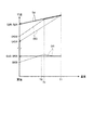
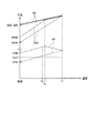
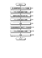
図4は、接合装置1を利用した接合対象100同士の接合方法を示すフローチャートである。図5A、図5B、図6A、図6B、図7A、図7B、図8A、図8B、図9A、及び図9Bは、図4に示した接合方法を説明する図である。具体的に、図5A、図6A、図7A、図8A、及び図9Aは、図3Aに対応した図である。図5B、図6B、図7B、図8B、図9Bは、図3Bに対応した図である。図10は、図4に示した接合方法を実施した際での凹部21の内径寸法DjI、フランジ102の外径寸法DfO、及び接合用挿入部1021の内径寸法DfIの変化を示す図である。
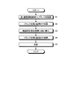
(Joining method)
Next, a method for joining the objects to be joined 100 using the joining
FIG. 4 is a flowchart illustrating a method for joining the objects to be joined 100 using the joining
なお、以下で説明する接合方法では、軸部材101の熱膨張による当該軸部材101の外径寸法DsO(図3A,図3B)の変化は、他の寸法DjI,DfO,DfIの変化に比較して小さいため、「0(変化しない)」としている(図10)。また、図10では、凹部21の内径寸法DjIとして、当該接合方法の実施前(室温時)を内径寸法DjIBとし、当該接合方法の完了後(室温時)を内径寸法DjIAとしている。フランジ102の外径寸法DfOについても、当該接合方法の実施前(室温時)を外径寸法DfOBとし、当該接合方法の完了後(室温時)を外径寸法DfOAとしている。また、接合用挿入部1021の内径寸法DfIについても、当該接合方法の実施前(室温時)を内径寸法DfIBとし、当該接合方法の完了後(室温時)を内径寸法DfIAとしている。さらに、以下で説明する接合方法では、図10に示すように、当該接合方法の実施前(室温時)において、軸部材101の外径寸法DsOを接合用挿入部1021の内径寸法DfI(DfIB)よりも大きいものとしている。
In the joining method described below, the change in the outer diameter dimension DsO (FIGS. 3A and 3B) of the
先ず、作業者は、図5Aまたは図5Bに示すように、第1膨張規制部材2(凹部21)の中心軸Axjとフランジ102の中心軸Axfとが一致するように、第1膨張規制部材2(凹部21内)にフランジ102を設置する(ステップS1:第2部材設置工程)。この状態では、室温時であり、上述したように、凹部21の内径寸法DjI(DjIB)がフランジ102の外径寸法DfO(DfOB)よりも大きいため、図5Aまたは図5Bに示すように、凹部21の内周面とフランジ102の外周面との間には隙間が空いた状態となる。また、作業者は、軸部材101を軸部材把持部4に設置する(図5A)。
First, as shown in FIG. 5A or FIG. 5B, the operator places the first
次に、作業者は、高周波電源(図示略)から電磁誘導加熱コイル3に高周波電流を供給し、第1膨張規制部材2を誘導加熱する(ステップS2:接合前加熱工程)。そして、凹部21内に設置されたフランジ102は、第1膨張規制部材2から熱が伝達されることにより、温度上昇する。
このステップS2が実施されることで、第1膨張規制部材2及びフランジ102は、熱膨張する(図6A,図6B)。そして、凹部21の内径寸法DjI、フランジ102の外径寸法DjO、及び接合用挿入部1021の内径寸法DfIは、図10に示すように、徐々に大きくなる。
ここで、上述したように、第1膨張規制部材2の線膨張係数βは、フランジ102の線膨張係数αよりも小さいものである。このため、フランジ102の外径寸法DfOは、図10に示すように、凹部21の内径寸法DjIよりも大きく変化する。一方、接合用挿入部1021の内径寸法DfIは、フランジ102の外径寸法DfOよりも小さいため、当該外径寸法DfOよりも緩やかに変化する。
そして、ステップS2では、作業者は、フランジ102が第2温度T2となるまで、第1膨張規制部材2を誘導加熱する。なお、第2温度T2は、図10に示すように、接合用挿入部1021の内径寸法DfIが軸部材101の外径寸法DsOよりも大きい状態となる温度である。
Next, the operator supplies a high-frequency current to the electromagnetic
By performing this step S2, the first
Here, as described above, the linear expansion coefficient β of the first
In step S2, the operator induction heats the first
次に、作業者は、高周波電源(図示略)から電磁誘導加熱コイル3への高周波電流の供給を停止し(第1膨張規制部材2の誘導加熱(フランジ102の加熱)を停止し)、図7Aまたは図7Bに示すように、軸部材把持部4を動作させて、フランジ102の中心軸Axfと軸部材101の中心軸Axsとが一致するように、軸部材101を接合用挿入部1021に挿入する(ステップS3:第1部材挿入工程)。この際、軸部材101において、接合用挿入部1021から突出した下方側の端部は、図7Aに示すように、挿通孔211に挿通される。
Next, the operator stops the supply of the high-frequency current from the high-frequency power source (not shown) to the electromagnetic induction heating coil 3 (stops the induction heating (heating of the flange 102) of the first expansion regulating member 2). As shown in FIG. 7A or 7B, the shaft
次に、作業者は、高周波電源(図示略)から電磁誘導加熱コイル3に高周波電流を供給し、フランジ102が第1温度T1となるまで、第1膨張規制部材2を改めて誘導加熱する(ステップS4:追加加熱工程)。なお、第1温度T1は、図10に示すように、第2温度T2よりも高い温度である。
このステップS4でフランジ102を第1温度T1まで加熱すると、フランジ102は、以下の挙動を示す。
すなわち、フランジ102及び第1膨張規制部材2は、図8A、図8B、または図10に示すように、熱膨張する。そして、フランジ102及び第1膨張規制部材2の線膨張係数α,βの差により、膨張規制温度Tx(第1温度T1よりも小さい温度(図10))になった時点で、凹部21の内径寸法DjIとフランジ102の外径寸法DfOとが一致する(凹部21の内周面にフランジ102の外周面が当接する)。
この後、フランジ102が膨張規制温度Tx以上になっていく過程において、フランジ102は、熱膨張しようとするが、凹部21の内周面にて機械的に規制されている。このため、フランジ2は、凹部21にて機械的に規制されていない方向、すなわち、高さ方向、及び接合用挿入部1021の内径寸法DfIが縮径する方向に塑性変形する。そして、接合用挿入部1021の内径寸法DfIは、図10に示すように、膨張規制温度Txを超えると、徐々に小さくなる。また、当該接合用挿入部1021の縮径は、軸部材101の外周面にて機械的に規制される。すなわち、接合用挿入部1021の内径寸法DfIは、最終的に、軸部材101の外径寸法DsOに一致する。
Next, the operator supplies a high-frequency current to the electromagnetic
When the
That is, the
Thereafter, in the process in which the
次に、作業者は、高周波電源(図示略)から電磁誘導加熱コイル3への高周波電流の供給を停止し(第1膨張規制部材2の誘導加熱(フランジ102の加熱)を停止し)、第1膨張規制部材2及びフランジ102を室温まで冷却する(ステップS5:冷却工程)。
このステップS5での冷却により、フランジ102及び第1膨張規制部材2は、図9A,図9B、または図10に示すように、収縮する。具体的に、凹部21の内径寸法DjIは、図10に破線の矢印で示したように、第1膨張規制部材2の収縮に応じて徐々に小さくなり、最終的に、当該接合方法の実施前の内径寸法DjIBと同一の内径寸法DjIAとなる。また、フランジ102の外径寸法DfOは、図10に破線の矢印で示したように、当該フランジ102の収縮に応じて徐々に小さくなり、最終的に、当該接合方法の実施前の外径寸法DfOBよりも小さい外径寸法DfOAとなる。さらに、接合用挿入部1021の内径寸法DfIは、図10に破線の矢印で示したように、当該フランジ102の収縮に応じて徐々に小さくなろうとするが、当該収縮が軸部材101の外周面にて機械的に規制されているため、最終的に、軸部材101の外径寸法DsOに一致した内径寸法DfIAを維持する。
以上の工程により、軸部材101及びフランジ102は、互いに接合される。
Next, the operator stops the supply of the high-frequency current from the high-frequency power source (not shown) to the electromagnetic induction heating coil 3 (stops the induction heating (heating of the flange 102) of the first expansion regulating member 2), and the first 1 The
By the cooling in step S5, the
Through the above steps, the
以上説明した本実施の形態1に係る接合方法では、以下の効果を有する。
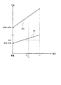
図11ないし図13は、本実施の形態1の効果を説明する図である。具体的に、図11及び図12は、図10に対応した図であって、接合用挿入部1021に軸部材101を挿入せずに(第1部材挿入工程S3を省略して)図4に示した接合方法を実施した場合での凹部21の内径寸法DjI、フランジ102の外径寸法DfO、及び接合用挿入部1021の内径寸法DfIの変化を示す図である。また、図11では、図10と同様に、当該接合方法の実施前(室温時)において、軸部材101の外径寸法DsOを接合用挿入部1021の内径寸法DfI(DfIB)よりも大きいものとしている。一方、図12では、当該接合方法の実施前(室温時)において、軸部材101の外径寸法DsOを接合用挿入部1021の内径寸法DfI(DfIB)よりも小さいものとしている。図13は、接合用挿入部1021に軸部材101を挿入せずに、第1膨張規制部材2を用いない従来の焼き嵌めを実施した場合でのフランジ102の外径寸法DfO、及び接合用挿入部1021の内径寸法DfIの変化を示す図である。
The bonding method according to the first embodiment described above has the following effects.
11 to 13 are diagrams for explaining the effect of the first embodiment. Specifically, FIGS. 11 and 12 correspond to FIG. 10, and the
ここで、軸部材101とフランジ102との接合強度を示す締め代について考察する。
本来、締め代は、接合前(室温時)において、軸部材101の外径寸法DsOから接合用挿入部1021の内径寸法DfIBを差し引いた寸法(寸法DsO−寸法DfIB)で定義することができる(以下、第1定義と記載)。しかしながら、本実施の形態1では、接合方法の過程(追加加熱工程S4)で、接合用挿入部1021を縮径する方向に塑性変形させているため、締め代を第1定義とは異なる定義で考える必要がある。
Here, the fastening allowance indicating the bonding strength between the
Originally, the fastening allowance can be defined by a dimension (dimension DsO−dimension DfIB) obtained by subtracting the inner diameter dimension DfIB of the
具体的に、従来の焼き嵌めでは、第1膨張規制部材2を用いない。このため、接合用挿入部1021は、縮径する方向に塑性変形しない。すなわち、接合用挿入部1021の内径寸法DfIは、接合用挿入部1021に軸部材101が挿入されていなければ、図13に示すように、従来の焼き嵌めを実施する前の内径寸法DfIBと、従来の焼き嵌めを完了した後の内径寸法DfIAとが同一となる。このため、従来の焼き嵌めでは、軸部材101とフランジ102との接合強度を示す締め代を第1定義で考えればよい。
Specifically, the first
一方、本実施の形態1の接合方法では、第1膨張規制部材2を用いているため、接合用挿入部1021は、追加加熱工程S4において、縮径する方向に塑性変形する(図11)。すなわち、接合用挿入部1021の内径寸法DfIは、接合用挿入部1021に軸部材101が挿入されていなければ、図11に示すように、当該接合方法を実施する前の内径寸法DfIBよりも当該接合方法を完了した後の内径寸法DfIAが小さくなる。このため、本実施の形態1の接合方法では、軸部材101とフランジ102との接合強度を示す締め代の定義として、接合方法を完了した後(室温時)において、軸部材101の外径寸法DsOから接合用挿入部1021の内径寸法DfIAを差し引いた寸法(寸法DsO−寸法DfIA)とする第2定義を採用する必要がある。
On the other hand, in the joining method of the first embodiment, since the first
そして、図11及び図13を比較して分かるように、同一の材料及び寸法で構成された軸部材101及びフランジ102を本実施の形態1に係る接合方法(図11)、及び従来の焼き嵌め(図13)でそれぞれ互いに接合した場合には、本実施の形態1に係る接合方法の締め代(第2定義(寸法DsO−寸法DfIA))は、従来の焼き嵌めの締め代(第1定義(寸法DsO−寸法DfIB))よりも大きくなる。このため、本実施の形態1に係る接合方法を採用すれば、従来の焼き嵌めに比較して、軸部材101とフランジ102との接合強度を向上させることができる。
Then, as can be seen by comparing FIG. 11 and FIG. 13, the
ここで、従来の焼き嵌めでは、当該焼き嵌めを実施する前(室温時)において、接合用挿入部1021の内径寸法DfIBが軸部材101の外径寸法DsOよりも大きいフランジ102を用いた場合には、締め代(第1定義)を確保することができない。このため、軸部材101とフランジ102とを互いに接合することができない。
これに対して、本実施の形態1の接合方法では、追加加熱工程S4において、接合用挿入部1021を縮径する方向に塑性変形させる。このため、図12に示すように、当該接合方法を実施する前(室温時)において、接合用挿入部1021の内径寸法DfIBが軸部材101の外径寸法DsOよりも大きいフランジ102を用いた場合であっても、十分な締め代(第2定義(寸法DsO−寸法DfIA))を確保することができる。すなわち、軸部材101とフランジ102とを互いに接合することができる。したがって、第1定義の締め代で考えた場合には、締め代(第1定義)がマイナスの値でも軸部材101とフランジ102とを接合することができ、当該締め代(第1定義)の範囲が広くなる。すなわち、軸部材101とフランジ102との加工公差を狭い範囲で管理する必要がない。
以上のことから、本実施の形態1に係る接合方法によれば、軸部材101及びフランジ102の加工管理を容易にしつつ、所望の接合強度を得ることができる、という効果を奏する。
Here, in the conventional shrink fitting, before the shrink fitting is performed (at room temperature), when the
On the other hand, in the joining method of the first embodiment, in the additional heating step S4, the joining
From the above, according to the joining method according to the first embodiment, it is possible to obtain a desired joining strength while facilitating the processing management of the
(実施の形態2)
次に、本発明の実施の形態2について説明する。
以下の説明では、上述した実施の形態1と同様の構成には同一符号を付し、その詳細な説明は省略または簡略化する。
本実施の形態2に係る接合方法では、上述した実施の形態1で説明した接合方法により軸部材101及びフランジ102を互いに接合した後、当該接合した接合ワークに対して、再度、追加加熱工程及び冷却工程を実施する点が異なる。
以下、本実施の形態2に係る接合方法について説明する。
(Embodiment 2)
Next, a second embodiment of the present invention will be described.
In the following description, the same reference numerals are given to the same components as those in the first embodiment described above, and detailed description thereof will be omitted or simplified.
In the joining method according to the second embodiment, after the
Hereinafter, the joining method according to the second embodiment will be described.
〔接合方法〕
図14は、本実施の形態2に係る接合方法を示すフローチャートである。図15A、図15B、図16A、図16B、図17A、及び図17Bは、図14に示した接合方法を説明する図である。具体的に、図15A,図16A、及び図17Aは、図3Aに対応した図である。図15B、図16B、及び図17Bは、図3Bに対応した図である。
本実施の形態2に係る接合方法は、図14に示すように、上述した実施の形態1で説明した接合方法(図4)に対して、ステップS1A,S4A,S5Aが追加されている点が異なるのみである。このため、以下では、ステップS1A,S4A,S5Aのみを順に説明する。
(Joining method)
FIG. 14 is a flowchart showing the bonding method according to the second embodiment. 15A, FIG. 15B, FIG. 16A, FIG. 16B, FIG. 17A, and FIG. 17B are diagrams for explaining the joining method shown in FIG. Specifically, FIGS. 15A, 16A, and 17A correspond to FIG. 3A. 15B, FIG. 16B, and FIG. 17B are diagrams corresponding to FIG. 3B.
As shown in FIG. 14, the joining method according to the second embodiment has steps S1A, S4A, and S5A added to the joining method described in the first embodiment (FIG. 4). Only different. For this reason, below, only step S1A, S4A, and S5A are demonstrated in order.
〔ステップS1A〕
ステップS1A(接合ワーク設置工程)は、ステップS5の後に実施される。
具体的に、作業者は、ステップS1Aにおいて、図15Aまたは図15Bに示すように、ステップS1〜S5で用いた第1膨張規制部材2を第2膨張規制部材2Aに変更する。
ここで、第2膨張規制部材2Aは、本発明に係る膨張規制部材に相当する。この第2膨張規制部材2Aは、第1膨張規制部材2と同一の材料で構成され、第1膨張規制部材2に対して、凹部21とは内径寸法が異なる凹部21A(本発明に係る設置用挿入部)を有している点が異なるのみである。なお、凹部21Aの内径寸法DjI´(図15B)は、室温時において、凹部21の内径寸法DjIよりも小さく、ステップS5を実施した後のフランジ102の外径寸法DfO(DfOA)よりも大きく設定されている。
また、作業者は、図15Aに示すように、ステップS1〜S5により軸部材101及びフランジ102が互いに接合された接合ワークWを軸部材把持部4に設置する。そして、作業者は、図15Aまたは図15Bに示すように、軸部材把持部4を動作させて、接合ワークWの中心軸Axf,Axsと第2膨張規制部材2A(凹部21A)の中心軸Axjとが一致するように、第2膨張規制部材2A(凹部21A内)に接合ワークWを設置する。この状態では、室温時であり、上述したように、凹部21Aの内径寸法DjI´は、フランジ102の外径寸法DfO(DfOA)よりも大きいため、図15Aまたは図15Bに示すように、凹部21Aの内周面とフランジ102の外周面との間には隙間が空いた状態となる。
[Step S1A]
Step S1A (joined workpiece installation step) is performed after step S5.
Specifically, in step S1A, the worker changes the first
Here, the second
Further, as shown in FIG. 15A, the worker installs the workpiece W to which the
〔ステップS4A〕
ステップS4A(追加加熱工程)は、ステップS1Aの後に実施される。
具体的に、作業者は、ステップS4Aにおいて、ステップS4と同様に、フランジ102が第1温度T1となるまで第2膨張規制部材2Aを誘導加熱し、図16Aまたは図16Bに示すように、フランジ102を熱膨張させる。
なお、ステップS4Aでの第1温度T1は、ステップS4での第1温度T1と同一であってもよく、あるいは、異なる温度であっても構わない。具体的に、ステップS4Aでの第1温度T1は、フランジ部102及び第2膨張規制部材2Aの熱膨張に応じて、凹部21Aの内径寸法DjI´とフランジ102の外径寸法DfOとが一致する膨張規制温度を超える温度であればよい。
上述したように、凹部21Aの内径寸法DjI´は、凹部21の内径寸法DjIよりも小さく設定されている。このため、ステップS4Aを実施することで、フランジ102の熱膨張は、ステップS4の時よりも、第2膨張規制部材2A(凹部21A)の内周面にてより強く機械的に規制される。すなわち、接合用挿入部1021に縮径しようとする力がさらに働くこととなる。
[Step S4A]
Step S4A (additional heating step) is performed after step S1A.
Specifically, in step S4A, the operator performs induction heating of the second
Note that the first temperature T1 in step S4A may be the same as or different from the first temperature T1 in step S4. Specifically, in the first temperature T1 in step S4A, the inner diameter dimension DjI ′ of the
As described above, the inner diameter dimension DjI ′ of the
〔ステップS5A〕
ステップS5A(冷却工程)は、ステップS4Aの後に実施される。
具体的に、作業者は、ステップS5Aにおいて、ステップS5と同様に、第2膨張規制部材2Aの誘導加熱を停止して第2膨張規制部材2A及びフランジ102を室温まで冷却し、図17Aまたは図17Bに示すように、フランジ102を収縮させる。このステップS5Aを実施することで、フランジ102の収縮により、接合用挿入部1021に縮径しようとする力がさらに働くこととなる。
[Step S5A]
Step S5A (cooling step) is performed after step S4A.
Specifically, in step S5A, the operator stops the induction heating of the second
以上説明した本実施の形態2に係る接合方法によれば、上述した実施の形態1と同様の効果を奏する。
また、本実施の形態2に係る接合方法では、ステップS1〜S5により軸部材101及びフランジ102が互いに接合された接合ワークWに対して、追加加熱工程S4で用いた第1膨張規制部材2における凹部21の内径寸法DjIよりも小さい内径寸法DjI´の凹部21Aを有する第2膨張規制部材2Aを用いて、改めて追加加熱工程S4A及び冷却工程S5Aを実施する。このため、ステップS1〜S5で得られた接合強度よりも高い接合強度を得ることができる。
また、ステップS1〜S5で所望の接合強度を得ることができていなくても、追加加熱工程S4A及び冷却工程S5Aにより接合強度を向上させることで所望の接合強度を得ることが可能となる。このため、第1定義の締め代で考えた場合には、当該締め代(第1定義)の範囲をさらに広くすることができる。すなわち、軸部材101とフランジ102との加工公差を狭い範囲で管理する必要がなく、軸部材101及びフランジ102の加工管理をさらに容易とする。
According to the joining method according to the second embodiment described above, the same effects as those of the first embodiment described above can be obtained.
Further, in the joining method according to the second embodiment, the first
Moreover, even if the desired bonding strength cannot be obtained in steps S1 to S5, it is possible to obtain the desired bonding strength by improving the bonding strength by the additional heating step S4A and the cooling step S5A. For this reason, when considering the tightening allowance of the first definition, the range of the allowance (first definition) can be further widened. That is, it is not necessary to manage the processing tolerance between the
ここで、上述した実施の形態1において、第1膨張規制部材2の代わりに第2膨張規制部材2Aを用いて接合方法(図4)を実施することも考えられる。
この場合には、凹部21Aの内径寸法DjI´が小さいため、加熱温度の低い段階で、フランジ2の熱膨張が第2膨張規制部材2A(凹部21A)の内周面にて機械的に規制され、接合用挿入部1021の縮径が始まる。その結果、接合用挿入部1021は、あまり拡がることができない。そして、第1定義の締め代で考えた場合には、軸部材101とフランジ102とを接合することができる締め代(第1定義)の上限が小さくなる。また、冷却後の接合用挿入部1021の内径寸法DfIはより小さくなるため、軸部材101とフランジ102とを接合することができる締め代(第1定義)の下限は小さくなる。結果的に、凹部21Aの内径寸法DjI´の小さい第2膨張規制部材2Aを用いたとしても、軸部材101とフランジ102とを接合することができる締め代(第1定義)の範囲や、所望の接合強度を得ることができる締め代(第1定義)の範囲は第1膨張規制部材2を用いた場合とほとんど変わらない。
そして、第1膨張規制部材2の代わりに第2膨張規制部材2Aを用いて接合方法(図4)を実施するよりも、本実施の形態2に係る接合方法のように、ステップS1〜S5により軸部材101及びフランジ102が互いに接合された接合ワークWに対して、改めて追加加熱工程S4A及び冷却工程S5Aを実施した方が、軸部材101とフランジ102とを接合することができる締め代(第1定義)の範囲や、所望の接合強度を得ることができる締め代(第1定義)の範囲を広くすることができる。
Here, in
In this case, since the inner diameter DjI ′ of the
Then, rather than performing the joining method (FIG. 4) using the second
(実施例)
次に、本発明の効果を具体的な実施例に基づいて説明する。
〔実施例1〕
本実施例1では、以下の材料及び寸法で構成された軸部材101及びフランジ102を用い、上述した実施の形態1で説明した接合方法(図4)により、軸部材101及びフランジ102を互いに接合した。以下、説明の便宜上、上述した実施の形態1で説明した接合方法(図4)を単発接合方法と記載する。
軸部材101を構成する材料:チタン合金
軸部材101における接合部位の長さ:4mm
軸部材101の外径寸法DsO:3.52mm
フランジ102を構成する材料:アルミ合金(A7075)
接合用挿入部1021の外径寸法DfO:6mm
接合用挿入部1021の内径寸法DfI(DfIB):3.5mm
凹部21の内径寸法DjI:6.03mm
なお、接合前加熱工程S2での第2温度T2は、300℃に設定した。また、追加加熱工程S4での第1温度T1は、450℃に設定した。
(Example)
Next, the effect of this invention is demonstrated based on a specific Example.
[Example 1]
In Example 1, the
Material constituting shaft member 101: Titanium alloy Length of joint portion of shaft member 101: 4 mm
The outer diameter DsO of the shaft member 101: 3.52 mm
Material constituting flange 102: Aluminum alloy (A7075)
Outer diameter DfO of the joining insertion portion 1021: 6 mm
Inner diameter DfI (DfIB) of the
Inner diameter DjI of recess 21: 6.03 mm
In addition, 2nd temperature T2 in heating process S2 before joining was set to 300 degreeC. Moreover, 1st temperature T1 in additional heating process S4 was set to 450 degreeC.
〔実施例2〕
本実施例2では、軸部材101の外径寸法DsOを3.51mmとした以外は、上述した実施例1と同一材料及び寸法で構成された軸部材101及びフランジ102を用い、上述した実施例1と同様の単発接合方法により、軸部材101及びフランジ102を互いに接合した。
[Example 2]
In the second embodiment, the
〔実施例3〕
本実施例3では、軸部材101の外径寸法DsOを3.50mmとした以外は、上述した実施例1と同一材料及び寸法で構成された軸部材101及びフランジ102を用い、上述した実施例1と同様の単発接合方法により、軸部材101及びフランジ102を互いに接合した。
Example 3
In the third embodiment, the
〔実施例4〕
本実施例4では、軸部材101の外径寸法DsOを3.49mmとした以外は、上述した実施例1と同一材料及び寸法で構成された軸部材101及びフランジ102を用い、上述した実施例1と同様の単発接合方法により、軸部材101及びフランジ102を互いに接合した。
Example 4
The fourth embodiment uses the
〔実施例5〕
本実施例5では、軸部材101の外径寸法DsOを3.48mmとした以外は、上述した実施例1と同一材料及び寸法で構成された軸部材101及びフランジ102を用い、上述した実施例1と同様の単発接合方法により、軸部材101及びフランジ102を互いに接合した。
Example 5
In the fifth embodiment, the
〔実施例6〕
本実施例6では、上述した実施例1と同一の材料及び寸法で構成された軸部材101及びフランジ102を用い、上述した実施の形態2で説明した接合方法(図14)により、軸部材101及びフランジ102を互いに接合した。以下、説明の便宜上、上述した実施の形態2で説明した接合方法(図14)を繰返し接合方法と記載する。
なお、凹部21Aの内径寸法DjI´は、6.01mmに設定した。また、追加加熱工程S4Aでの第1温度T1は、450℃に設定した。
Example 6
In Example 6, the
The inner diameter DjI ′ of the
〔実施例7〕
本実施例7では、上述した実施例2と同一の材料及び寸法で構成された軸部材101及びフランジ102を用い、上述した実施例6と同様の繰返し接合方法により、軸部材101及びフランジ102を互いに接合した。
Example 7
In the seventh embodiment, the
〔実施例8〕
本実施例8では、上述した実施例3と同一の材料及び寸法で構成された軸部材101及びフランジ102を用い、上述した実施例6と同様の繰返し接合方法により、軸部材101及びフランジ102を互いに接合した。
Example 8
In the eighth embodiment, the
〔実施例9〕
本実施例9では、上述した実施例4と同一の材料及び寸法で構成された軸部材101及びフランジ102を用い、上述した実施例6と同様の繰返し接合方法により、軸部材101及びフランジ102を互いに接合した。
Example 9
In the ninth embodiment, the
〔実施例10〕
本実施例10では、上述した実施例5と同一の材料及び寸法で構成された軸部材101及びフランジ102を用い、上述した実施例6と同様の繰返し接合方法により、軸部材101及びフランジ102を互いに接合した。
Example 10
In the tenth embodiment, the
〔比較例1〕
本比較例1では、上述した実施例1と同一の材料及び寸法で構成された軸部材101及びフランジ102を用い、第1,第2膨張規制部材2,2Aを用いない従来の焼き嵌めにより、軸部材101及びフランジ102を互いに接合した。
[Comparative Example 1]
In this comparative example 1, the
〔比較例2〕
本比較例2では、上述した実施例2と同一の材料及び寸法で構成された軸部材101及びフランジ102を用い、上述した比較例1と同様の従来の焼き嵌めにより、軸部材101及びフランジ102を互いに接合した。
[Comparative Example 2]
In the second comparative example, the
〔比較例3〕
本比較例3では、上述した実施例3と同一の材料及び寸法で構成された軸部材101及びフランジ102を用い、上述した比較例1と同様の従来の焼き嵌めにより、軸部材101及びフランジ102を互いに接合した。
[Comparative Example 3]
In this comparative example 3, the
〔比較例4〕
本比較例4では、上述した実施例4と同一の材料及び寸法で構成された軸部材101及びフランジ102を用い、上述した比較例1と同様の従来の焼き嵌めにより、軸部材101及びフランジ102を互いに接合した。
[Comparative Example 4]
In this comparative example 4, the
〔比較例5〕
本比較例5では、上述した実施例5と同一の材料及び寸法で構成された軸部材101及びフランジ102を用い、上述した比較例1と同様の従来の焼き嵌めにより、軸部材101及びフランジ102を互いに接合した。
[Comparative Example 5]
In the present comparative example 5, the
〔評価及び結果〕
評価方法としては、実施例1〜10及び比較例1〜5にて互いに接合された軸部材101及びフランジ102の一方を固定し、中心軸Axf,Axsを中心として他方を回転させ、当該他方が当該一方から外れた時の力(回転方向接合強度(N・m))をそれぞれ測定した。なお、測定装置の測定レンジが3N・mまでであったため、回転方向接合強度としては、3N・m以上を測定していない。また、所望の回転方向接合強度は、3N・m以上である。そして、結果は、以下の表1に示す通りである。
[Evaluation and results]
As an evaluation method, one of the

〔従来の焼き嵌めの結果〕
従来の焼き嵌めでは、表1に示すように、軸部材101の外径寸法DsOが接合用挿入部1021の内径寸法DfIB以下の場合(比較例3〜5)には、軸部材101とフランジ102とを接合することができなかった。また、比較例1,2では、軸部材101とフランジ102とを接合することができたが、所望の回転方向接合強度(3N・m以上)を得ることはできなかった。
すなわち、第1定義の締め代で考えた場合には、従来の焼き嵌めにおいて、軸部材101とフランジ102とを接合することができる締め代(第1定義)の範囲は、0.01〜0.02mmである。
[Results of conventional shrink fitting]
In the conventional shrink fitting, as shown in Table 1, when the outer diameter DsO of the
That is, when considering the tightening allowance of the first definition, the range of the tightening allowance (first definition) in which the
〔単発接合方法の結果〕
本発明の単発接合方法では、表1に示すように、全ての実施例1〜5において、軸部材101とフランジ102とを接合することができた。しかしながら、実施例4,5では、軸部材101とフランジ102とを接合することができたが、所望の回転方向接合強度(3N・m以上)を得ることはできなかった。
すなわち、第1定義の締め代で考えた場合には、本発明の単発接合方法において、軸部材101とフランジ102とを接合することができる締め代(第1定義)の範囲は、-0.02mm〜0.02mmであり、従来の焼き嵌めに対して広くなった。また、所望の回転方向接合強度(3N・m以上)を得ることができる締め代(第1定義)の範囲は、0〜0.02mmであり、従来の焼き嵌めに対して広くなった。
[Results of single bonding method]
In the single joining method of the present invention, as shown in Table 1, in all Examples 1 to 5, the
That is, when considering the tightening allowance of the first definition, the range of the tightening allowance (first definition) in which the
〔繰返し接合方法の結果〕
本発明の繰返し接合方法では、表1に示すように、全ての実施例6〜10において、軸部材101とフランジ102とを接合することができ、さらに、所望の回転方向接合強度(3N・m以上)を得ることができた。
すなわち、第1定義の締め代で考えた場合には、本発明の繰返し接合方法において、軸部材101とフランジ102とを接合することができる締め代(第1定義)の範囲、及び所望の回転方向接合強度(3N・m以上)を得ることができる締め代(第1定義)の範囲は、-0.02mm〜0.02mmである。すなわち、本発明の繰返し接合方法では所望の回転方向接合強度(3N・m以上)を得ることができる締め代(第1定義)の範囲は、単発接合方法に対して広くなった。
[Results of repeated joining method]
In the repeated joining method of the present invention, as shown in Table 1, in all Examples 6 to 10, the
That is, when considering the tightening allowance of the first definition, in the repetitive joining method of the present invention, the range of the tightening allowance (first definition) in which the
(その他の実施の形態)
ここまで、本発明を実施するための形態を説明したが、本発明は上述した実施の形態によってのみ限定されるべきものではない。
上述した実施の形態1,2では、第1,第2膨張規制部材2,2Aは、フランジ102の熱膨張を機械的に規制する際、フランジ102の外周面を機械的に規制していたが、これに限らない。フランジ102の熱膨張を機械的に規制し、接合用挿入部1021を縮径する方向に塑性変形することができれば、例えば、フランジ102の上端面及び下端面を機械的に規制する構成を採用しても構わない。
(Other embodiments)
The embodiments for carrying out the present invention have been described so far, but the present invention should not be limited only by the above-described embodiments.
In the first and second embodiments described above, the first and second
上述した実施の形態1,2において、接合装置1を用い、従来の焼き嵌めを実施した接合ワーク(例えば、比較例1,2で互いに接合した軸部材101及びフランジ102)に対して、追加加熱工程S4(S4A)及び冷却工程S5(S5A)を実施しても構わない。このように従来の焼き嵌めを実施した接合ワークに対して追加加熱工程及び冷却工程を実施する接合方法も本発明に含まれるものである。
In the first and second embodiments described above, additional heating is performed on the joint work (for example, the
上述した実施の形態1,2において、軸部材101、フランジ102、及び第1,第2膨張規制部材2,2Aを構成する材料は、上述した実施の形態1,2で説明した材料に限らない。第1,第2膨張規制部材2,2Aの線膨張係数βがフランジ102の線膨張係数αよりも小さい条件を満たしていれば、第1,第2膨張規制部材2,2A及びフランジ102を構成する材料は、いずれの材料を用いても構わない。
また、第2膨張規制部材2Aは、第1膨張規制部材2と比較してフランジ102の熱膨張に対する機械的な規制が強い構成であれば、その材料(線膨張係数)及び寸法を第1膨張規制部材2と異なる構成としても構わない。
In the first and second embodiments described above, the materials constituting the
In addition, if the second
上述した実施の形態1,2では、第1部材挿入工程S3は、フランジ102が第2温度T2に達した後に実施していたが、これに限らない。フランジ102の熱膨張により、接合用挿入部1021の内径寸法DfIが軸部材101の外径寸法DsOよりも大きい状態であれば、いずれのタイミングで第1部材挿入工程S3を実施しても構わない。すなわち、第1部材挿入工程S3は、接合前加熱工程S2の際や、追加加熱工程S4の際に実施しても構わない。
In
上述した実施の形態1,2において、フランジ102を加熱する手段として、電磁誘導加熱コイル3を採用していたが、これに限らず、電磁誘導以外の方法でフランジ102を直接あるいは間接的に加熱する構成を採用しても構わない。
In the first and second embodiments described above, the electromagnetic
上述した実施の形態2では、追加加熱工程及び冷却工程を2回、繰り返し実施していたが、これに限らず、3回以上、繰り返し実施しても構わない。この際、上述した実施の形態2で説明したように、後段の追加加熱工程において、前段の追加加熱工程よりもフランジ102の熱膨張に対する機械的な規制が強い膨張規制部材に順次、変更する。
In the second embodiment described above, the additional heating step and the cooling step are repeated twice. However, the present invention is not limited to this, and the additional heating step and the cooling step may be repeated three times or more. At this time, as described in the above-described second embodiment, in the subsequent additional heating process, the expansion is sequentially changed to an expansion regulating member that has a stronger mechanical restriction on the thermal expansion of the
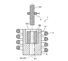
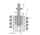
図18は、本実施の形態1,2の変形例を示す図である。具体的に、図18は、図3Aに対応した図である。
上述した実施の形態1,2で説明した接合装置1の代わりに、図18に示した接合装置1Bを採用しても構わない。
本変形例に係る接合装置1Bは、図18に示すように、上述した実施の形態1,2で説明した電磁誘導加熱コイル3及び軸部材把持部4の他、膨張規制部材2Bと、載置台5とを備える。
膨張規制部材2Bは、上述した実施の形態1で説明した第1,第2膨張規制部材2,2Aに対して、凹部21,21Aを下端まで貫通させた点が異なるのみである。
そして、凹部21,21Aを下端まで貫通させた部分は、当該凹部21,21Aと同様に、内周面にてフランジ102の熱膨張を機械的に規制する部分であり、本発明に係る設置用挿入部21Bに相当する。
載置台5は、上述した実施の形態1で説明した第1,第2膨張規制部材2,2Aにおける凹部21,21Aの底部に相当し、フランジ102が載置される部分である。そして、載置台5には、凹部21,21Aの底部に形成された挿通孔211に対応した挿通孔51を有する。
FIG. 18 is a diagram showing a modification of the first and second embodiments. Specifically, FIG. 18 is a diagram corresponding to FIG. 3A.
Instead of the joining
As shown in FIG. 18, the joining
The
And the part which penetrated the recessed
The mounting table 5 corresponds to the bottom of the
図19A及び図19Bは、本実施の形態1,2の変形例を示す図である。具体的に、図19Aは、図3Aに対応した図である。図19Bは、図3Bに対応した図である。
上述した実施の形態1,2で説明したフランジ102の代わりに、図19Aまたは図19Bに示したフランジ102Cを採用しても構わない。
本変形例に係るフランジ102Cは、上述した実施の形態1,2で説明したフランジ102に対して、接合用挿入部1021を下端まで貫通しない凹部1021Cで構成した点が異なるのみである。なお、凹部1021Cは、軸部材101が挿入される部分であり、本発明に係る接合用挿入部に相当する。
19A and 19B are diagrams showing modifications of the first and second embodiments. Specifically, FIG. 19A corresponds to FIG. 3A. FIG. 19B corresponds to FIG. 3B.
Instead of the
The
また、上述したフランジ102Cを採用した場合には、上述した実施の形態1,2で説明した接合装置1の代わりに、図19Aまたは図19Bに示した接合装置1Cを採用しても構わない。
本変形例に係る接合装置1Cは、図19Aまたは図19Bに示すように、上述した実施の形態1,2で説明した電磁誘導加熱コイル3及び軸部材把持部4の他、膨張規制部材2Cを備える。
膨張規制部材2Cは、図19Aに示すように、有底円筒形状を有する。そして、膨張規制部材2Cは、底部が上方に位置し、フランジ102Cの上端部を覆うように設置される。すなわち、膨張規制部材2Cの内面は、上述した実施の形態1で説明した第1,第2膨張規制部材2,2Aの凹部21,21Aと同様に、フランジ102の熱膨張を機械的に規制する部分であり、本発明に係る設置用挿入部21Cに相当する。
また、膨張規制部材2Cの底部には、当該膨張規制部材2Cの内外を貫通し、当該膨張規制部材2Cの外部から内部に向けて軸部材101を挿通するための設置用挿通孔22が形成されている。
When the
As shown in FIG. 19A or 19B, the joining
The
In addition, an
1,1B,1C 接合装置
2,2A 第1,第2膨張規制部材(膨張規制部材)
2B,2C 膨張規制部材
3 電磁誘導加熱コイル
4 軸部材把持部
5 載置台
21,21A 凹部(設置用挿入部)
21B,21C 設置用挿入部
22 設置用挿通孔
51 挿通孔
100 接合対象
101 軸部材
102,102C フランジ
211 挿通孔
1021 接合用挿入部
1021C 凹部(接合用挿入部)
Axf,Axj,Axs 中心軸
DfI,DfIA,DfIB 接合用挿入部の内径寸法
DfO,DfOA,DfOB フランジの外径寸法
DjI,DjIA,DjIB,DjI´ 凹部の内径寸法
DsO 軸部材の外径寸法
T1,T2 第1,第2温度
Tx 膨張規制温度
W 接合ワーク
1, 1B,
2B, 2C
21B, 21C
Axf, Axj, Axs Central axis DfI, DfIA, DfIB Inner diameter dimension of joint for insertion DfO, DfOA, DfOB Outer diameter dimension of flange DjI, DjIA, DjIB, DjI 'Inner diameter dimension of recess DsO Outer diameter dimension of shaft member T1, T2 First and second temperatures Tx Expansion restriction temperature W Joined workpiece
Claims (5)
膨張規制部材内に設置され、前記接合用挿入部に前記第1部材が挿入された前記第2部材を第1温度まで加熱し、当該第2部材の熱膨張を前記膨張規制部材の内面にて機械的に規制して前記接合用挿入部を縮径する方向に塑性変形させる追加加熱工程と、
前記追加加熱工程の後、前記第2部材を冷却して、前記第1部材と前記第2部材とを互いに接合する冷却工程とを備える
ことを特徴とする接合方法。 A joining method for joining two joining objects of a first member and a second member having a joining insertion portion into which the first member is inserted,
The second member installed in the expansion restricting member and having the first member inserted into the joining insertion portion is heated to a first temperature, and the thermal expansion of the second member is performed on the inner surface of the expansion restricting member. An additional heating step that mechanically regulates and plastically deforms in the direction of reducing the diameter of the joint insertion portion;
A cooling method comprising: a cooling step of cooling the second member after the additional heating step and bonding the first member and the second member to each other.
前記第2部材が挿入される設置用挿入部を有し、前記追加加熱工程の際、当該設置用挿入部の内面にて前記第2部材の熱膨張を機械的に規制し、
当該接合方法は、
前記設置用挿入部と前記第2部材の外面との間に隙間を有した状態で、当該設置用挿入部に前記第2部材を挿入する第2部材設置工程と、
前記第2部材設置工程の後、前記第2部材を前記第1温度よりも低い第2温度まで加熱し、当該第2部材を熱膨張させる接合前加熱工程と、
前記接合前加熱工程の際、当該接合前加熱工程の後、または前記追加加熱工程の際に実施され、前記接合用挿入部に前記第1部材を挿入する第1部材挿入工程とを備え、
前記追加加熱工程は、
前記接合前加熱工程の後に実施される
ことを特徴とする請求項1に記載の接合方法。 The expansion regulating member is
An installation insertion portion into which the second member is inserted, and mechanically restricting thermal expansion of the second member on the inner surface of the installation insertion portion during the additional heating step;
The joining method is
A second member installation step of inserting the second member into the installation insertion portion with a gap between the installation insertion portion and the outer surface of the second member;
After the second member installation step, the second member is heated to a second temperature lower than the first temperature, and the pre-joining heating step for thermally expanding the second member;
In the pre-bonding heating step, the first member insertion step is performed after the pre-bonding heating step or in the additional heating step, and the first member is inserted into the bonding insertion portion,
The additional heating step includes
The bonding method according to claim 1, wherein the bonding method is performed after the pre-bonding heating step.
前記第2部材の熱膨張に対する機械的な規制が強い前記膨張規制部材に順次、変更されながら、複数回、繰り返し実施される
ことを特徴とする請求項1または2に記載の接合方法。 The additional heating step and the cooling step include
The joining method according to claim 1, wherein the second member is repeatedly performed a plurality of times while being sequentially changed to the expansion restricting member that has a strong mechanical restriction on thermal expansion of the second member.
前記第2部材が挿入される設置用挿入部を有し、前記追加加熱工程の際、当該設置用挿入部の内面にて前記第2部材の熱膨張を機械的に規制し、
前記追加加熱工程及び前記冷却工程は、
前記設置用挿入部の内径寸法が小さい前記膨張規制部材に順次、変更されながら、複数回、繰り返し実施される
ことを特徴とする請求項3に記載の接合方法。 The expansion regulating member is
An installation insertion portion into which the second member is inserted, and mechanically restricting thermal expansion of the second member at the inner surface of the installation insertion portion during the additional heating step;
The additional heating step and the cooling step include
The joining method according to claim 3, wherein the joining method is repeatedly performed a plurality of times while being sequentially changed to the expansion regulating member having a small inner diameter of the installation insertion portion.
前記第2部材の線膨張係数よりも小さい
ことを特徴とする請求項1〜4のいずれか一つに記載の接合方法。 The linear expansion coefficient of the expansion regulating member is
It is smaller than the linear expansion coefficient of the said 2nd member. The joining method as described in any one of Claims 1-4 characterized by the above-mentioned.
Priority Applications (5)
| Application Number | Priority Date | Filing Date | Title |
|---|---|---|---|
| JP2016119077A JP6697959B2 (en) | 2016-06-15 | 2016-06-15 | Joining method |
| PCT/JP2017/020475 WO2017217245A1 (en) | 2016-06-15 | 2017-06-01 | Joining method |
| DE112017003005.6T DE112017003005T5 (en) | 2016-06-15 | 2017-06-01 | bonding process |
| CN201780032743.9A CN109311132B (en) | 2016-06-15 | 2017-06-01 | Bonding method |
| US16/212,786 US10906139B2 (en) | 2016-06-15 | 2018-12-07 | Joining method |
Applications Claiming Priority (1)
| Application Number | Priority Date | Filing Date | Title |
|---|---|---|---|
| JP2016119077A JP6697959B2 (en) | 2016-06-15 | 2016-06-15 | Joining method |
Publications (2)
| Publication Number | Publication Date |
|---|---|
| JP2017222000A true JP2017222000A (en) | 2017-12-21 |
| JP6697959B2 JP6697959B2 (en) | 2020-05-27 |
Family
ID=60663100
Family Applications (1)
| Application Number | Title | Priority Date | Filing Date |
|---|---|---|---|
| JP2016119077A Active JP6697959B2 (en) | 2016-06-15 | 2016-06-15 | Joining method |
Country Status (5)
| Country | Link |
|---|---|
| US (1) | US10906139B2 (en) |
| JP (1) | JP6697959B2 (en) |
| CN (1) | CN109311132B (en) |
| DE (1) | DE112017003005T5 (en) |
| WO (1) | WO2017217245A1 (en) |
Cited By (1)
| Publication number | Priority date | Publication date | Assignee | Title |
|---|---|---|---|---|
| WO2020189192A1 (en) * | 2019-03-18 | 2020-09-24 | オリンパス株式会社 | Bonding method and bonding apparatus |
Families Citing this family (1)
| Publication number | Priority date | Publication date | Assignee | Title |
|---|---|---|---|---|
| CN112548485A (en) * | 2020-10-27 | 2021-03-26 | 中国船舶重工集团公司第七0三研究所 | Non-impact press-fitting method for stationary blade ring of gas turbine |
Family Cites Families (12)
| Publication number | Priority date | Publication date | Assignee | Title |
|---|---|---|---|---|
| US3046649A (en) * | 1954-10-11 | 1962-07-31 | Helen E Brennan | Method of producing composite metal articles |
| BE664918A (en) * | 1964-06-11 | 1900-01-01 | ||
| JPS57194832A (en) * | 1981-05-25 | 1982-11-30 | Kawasaki Heavy Ind Ltd | Manufacture of double pipe |
| JPS59159409A (en) * | 1983-02-28 | 1984-09-10 | 株式会社東芝 | Mechanical element |
| JPS59202117A (en) * | 1983-05-02 | 1984-11-15 | Nisshin Steel Co Ltd | Production of double pipe |
| US4598857A (en) * | 1984-04-02 | 1986-07-08 | Kawasaki Jukogyo Kabushiki Kaisha | Method of producing double-wall composite pipes |
| JPS6137318A (en) * | 1984-07-30 | 1986-02-22 | Nippon Steel Corp | Production of double pipe |
| JPH08155746A (en) * | 1994-11-30 | 1996-06-18 | Nakajima Kokan Kk | Forming method for beam junction part of steel pipe column |
| AU2003902440A0 (en) * | 2003-05-20 | 2003-06-05 | Cladtek International Pty Ltd | Production of clad pipes |
| WO2011005125A2 (en) | 2009-07-10 | 2011-01-13 | Progressive Ip Limited | Improvements in & relating to improving the integrity of the union between components |
| DE102012025442A1 (en) * | 2012-12-21 | 2014-06-26 | Thyssenkrupp Presta Teccenter Ag | Method for assembling a camshaft |
| CN105014301B (en) * | 2015-06-04 | 2017-11-10 | 上海交通大学 | The plastic joining method of shroud ring part pull bar and gland |
-
2016
- 2016-06-15 JP JP2016119077A patent/JP6697959B2/en active Active
-
2017
- 2017-06-01 WO PCT/JP2017/020475 patent/WO2017217245A1/en active Application Filing
- 2017-06-01 CN CN201780032743.9A patent/CN109311132B/en active Active
- 2017-06-01 DE DE112017003005.6T patent/DE112017003005T5/en not_active Withdrawn
-
2018
- 2018-12-07 US US16/212,786 patent/US10906139B2/en active Active
Cited By (4)
| Publication number | Priority date | Publication date | Assignee | Title |
|---|---|---|---|---|
| WO2020189192A1 (en) * | 2019-03-18 | 2020-09-24 | オリンパス株式会社 | Bonding method and bonding apparatus |
| JP2020151786A (en) * | 2019-03-18 | 2020-09-24 | オリンパス株式会社 | Joining method and joining device |
| JP7091274B2 (en) | 2019-03-18 | 2022-06-27 | オリンパス株式会社 | Joining method and joining device |
| US11541486B2 (en) | 2019-03-18 | 2023-01-03 | Olympus Corporation | Connecting method and connecting apparatus |
Also Published As
| Publication number | Publication date |
|---|---|
| CN109311132B (en) | 2021-05-18 |
| CN109311132A (en) | 2019-02-05 |
| JP6697959B2 (en) | 2020-05-27 |
| US10906139B2 (en) | 2021-02-02 |
| US20190105741A1 (en) | 2019-04-11 |
| DE112017003005T5 (en) | 2019-02-28 |
| WO2017217245A1 (en) | 2017-12-21 |
Similar Documents
| Publication | Publication Date | Title |
|---|---|---|
| WO2017217245A1 (en) | Joining method | |
| CN105163881B (en) | Spinning thickens forming method and spinning thickens shaped device | |
| US20090113708A1 (en) | Method for joining components | |
| JP2007155133A (en) | Method and device for connecting plastic workpiece to another workpiece | |
| JP2010040422A (en) | Heater with shaft | |
| US20190381557A1 (en) | Joint component manufacturing method | |
| JP2013091314A (en) | Method for connecting plastic workpiece to further workpiece | |
| JP5410726B2 (en) | High frequency induction heating coil, manufacturing method thereof, and power transmission component for automobile | |
| JP2018092845A (en) | Induction heater, shrink fitting device and induction heating method | |
| JP2001011535A (en) | Cylinder shaft machining method, and cylinder shaft | |
| EP2620250A1 (en) | Heat treatment method for branch pipe welded portion | |
| JP2013031254A (en) | Method of manufacturing stator | |
| WO2020189192A1 (en) | Bonding method and bonding apparatus | |
| JP6878677B2 (en) | Ceramic heater | |
| RU2713033C1 (en) | Manufacturing method of rotors of ball gyroscopes | |
| JP2004286179A (en) | Gear unit and its manufacturing method | |
| JP6875805B2 (en) | Substrate support member with shaft and its manufacturing method | |
| JP6811583B2 (en) | Holding device and its manufacturing method | |
| JPWO2015029095A1 (en) | Heat treatment method and apparatus for welded structure | |
| JP2019217585A (en) | Joining device and joining method | |
| US11370071B2 (en) | Joining method for a medical device | |
| EP3578834A1 (en) | Fastening structure and fastening method | |
| JP2015110239A (en) | Friction welding method, moving blade repair method, friction welding device, moving blade, and restraint tool | |
| JP2007167882A (en) | Enlarge-working method for shaft | |
| JP2013099771A (en) | Method for production of composite member, composite member, and device for production thereof |
Legal Events
| Date | Code | Title | Description |
|---|---|---|---|
| A621 | Written request for application examination |
Free format text: JAPANESE INTERMEDIATE CODE: A621 Effective date: 20190311 |
|
| TRDD | Decision of grant or rejection written | ||
| A01 | Written decision to grant a patent or to grant a registration (utility model) |
Free format text: JAPANESE INTERMEDIATE CODE: A01 Effective date: 20200421 |
|
| A61 | First payment of annual fees (during grant procedure) |
Free format text: JAPANESE INTERMEDIATE CODE: A61 Effective date: 20200427 |
|
| R151 | Written notification of patent or utility model registration |
Ref document number: 6697959 Country of ref document: JP Free format text: JAPANESE INTERMEDIATE CODE: R151 |
|
| R250 | Receipt of annual fees |
Free format text: JAPANESE INTERMEDIATE CODE: R250 |