JP2017215225A - Magnetic field measurement device - Google Patents
Magnetic field measurement device Download PDFInfo
- Publication number
- JP2017215225A JP2017215225A JP2016109806A JP2016109806A JP2017215225A JP 2017215225 A JP2017215225 A JP 2017215225A JP 2016109806 A JP2016109806 A JP 2016109806A JP 2016109806 A JP2016109806 A JP 2016109806A JP 2017215225 A JP2017215225 A JP 2017215225A
- Authority
- JP
- Japan
- Prior art keywords
- light
- magnetic field
- incident
- gas cell
- optical
- Prior art date
- Legal status (The legal status is an assumption and is not a legal conclusion. Google has not performed a legal analysis and makes no representation as to the accuracy of the status listed.)
- Withdrawn
Links
Images


Abstract
Description
本発明は、磁場計測装置に関する。 The present invention relates to a magnetic field measurement apparatus.
上記磁場計測装置として、微小な磁場を測定可能な光ポンピング磁力計が開示されている(特許文献1)。 As the magnetic field measuring device, an optical pumping magnetometer capable of measuring a minute magnetic field is disclosed (Patent Document 1).
上記特許文献1の光ポンピング磁力計は、セル内に封入されたガス状態の原子群に、ポンプ光を照射して原子群を構成する原子のスピンの向きを揃える。原子のスピンの向きが揃った原子群にプローブ光としての直線偏光を照射する。測定対象としての例えば人体から発せられる磁場の強度によって上記原子のスピンの向きが変化する。照射された直線偏光は上記原子のスピンの影響を受けて偏光回転角が変化することから、偏光回転角を検出することによって、当該磁場の強度を測定可能としたものである。
The optical pumping magnetometer of
上記特許文献1の光ポンピング磁力計では、セル内を透過してきた後のプローブ光を反射させる少なくとも1つの反射ミラーを備え、セルを少なくとも2回以上横断してきたプローブ光の偏光回転角度を検出することから、高感度な磁場検出が可能であるとしている。
The optical pumping magnetometer of
上記特許文献1の光ポンピング磁力計は、高感度であるがゆえに、磁場の測定を阻害するノイズを取り除く必要がある。当該ノイズとして、地磁気などの外部磁気ノイズが挙げられる。
Since the optical pumping magnetometer of the above-mentioned
上記光ポンピング磁力計では、外部磁気ノイズの影響を低減するために、磁気シールド内にセルを配置すると共に、磁気シールド内部の残留磁気を打ち消すためのヘルムホルツコイルを備えている。 In the optical pumping magnetometer, in order to reduce the influence of external magnetic noise, a cell is arranged in the magnetic shield, and a Helmholtz coil for canceling the residual magnetism inside the magnetic shield is provided.
しかしながら、当該ノイズとして、外部磁気ノイズの他に、プローブ光が放出された空間における空気の振動などによる直線偏光回転ノイズを含む光学ノイズが挙げられる。
上記光ポンピング磁力計では、該光学ノイズに対する対策が施されていないという課題があった。
However, as the noise, in addition to external magnetic noise, optical noise including linearly polarized light rotation noise due to air vibration in the space where the probe light is emitted can be cited.
The optical pumping magnetometer has a problem that no countermeasure is taken against the optical noise.
本発明は、上述の課題の少なくとも一部を解決するためになされたものであり、以下の形態または適用例として実現することが可能である。 SUMMARY An advantage of some aspects of the invention is to solve at least a part of the problems described above, and the invention can be implemented as the following forms or application examples.
[適用例]本適用例に係る磁場計測装置は、直線偏光を照射する光照射手段と、入射した光によって励起されるアルカリ金属原子が充填されるガスセルと、前記光照射手段と前記ガスセルとの間の光軸上に配置され、入射した前記直線偏光をプローブ光と参照光とに分岐する第1光学手段と、入射した光の強度を検出する第1検出部及び第2検出部と、前記ガスセルを透過した前記プローブ光が入射する第1面と、前記参照光が入射する第2面とを有する第2光学手段と、前記第2光学手段の前記第2面に入射する前記参照光の強度を、前記ガスセルを透過した後の前記プローブ光の強度と同等とする第3光学手段と、を備え、前記第2光学手段は、前記第1面に入射した前記プローブ光を前記第1検出部と前記第2検出部とに分岐して入射させると共に、前記第2面から入射した前記参照光を前記第1検出部と前記第2検出部とに分岐して入射させることを特徴とする。 [Application Example] A magnetic field measurement apparatus according to this application example includes a light irradiation unit that irradiates linearly polarized light, a gas cell filled with alkali metal atoms excited by incident light, and the light irradiation unit and the gas cell. A first optical unit disposed on the optical axis between the first optical unit for branching the incident linearly polarized light into a probe beam and a reference beam, a first detector and a second detector for detecting the intensity of the incident beam, A second optical means having a first surface on which the probe light transmitted through the gas cell is incident and a second surface on which the reference light is incident; and the reference light incident on the second surface of the second optical means. Third optical means having an intensity equal to the intensity of the probe light after passing through the gas cell, wherein the second optical means detects the probe light incident on the first surface as the first detection light. Branching into the second detector and the second detector Causes, characterized in that is incident branches of the reference light incident from the second surface to said second detector and the first detector.
本適用例によれば、第3光学手段により、ガスセルを透過したプローブ光の強度と参照光の強度とを同等とする。そして、強度が同等となった参照光を第2光学手段により第1検出部と第2検出部とに分岐して入射させる。第1検出部と第2検出部とには、第2光学手段により分岐されたプローブ光と参照光とがそれぞれ入射することから、プローブ光に含まれる直線偏光回転ノイズを含む光学ノイズを参照光によって打ち消すことができる。つまり、プローブ光に含まれる直線偏光回転ノイズを含む光学ノイズを低減して、精度よく磁場測定が可能な磁場計測装置を提供することができる。 According to this application example, the third optical unit equalizes the intensity of the probe light transmitted through the gas cell and the intensity of the reference light. Then, the reference light having the same intensity is branched and incident on the first detection unit and the second detection unit by the second optical means. Since the probe light and the reference light branched by the second optical means are respectively incident on the first detection unit and the second detection unit, optical noise including linearly polarized light rotation noise included in the probe light is referred to as the reference light. Can be countered by. That is, it is possible to provide a magnetic field measurement apparatus capable of accurately measuring a magnetic field by reducing optical noise including linearly polarized light rotation noise included in probe light.
上記適用例に記載の磁場計測装置において、前記ガスセルを透過した前記プローブ光を反射して再び前記ガスセルに入射させるミラーをさらに備えることが好ましい。
この構成によれば、プローブ光はミラーによって反射して少なくとも2回ガスセルを透過することになるので、高感度な磁場計測装置を提供することができる。また、ミラーを非磁性とすれば、磁場源とガスセルとの間にミラーを配置しても、磁場源の磁場計測に影響を及ぼさない。
In the magnetic field measurement apparatus according to the application example described above, it is preferable that the magnetic field measurement apparatus further includes a mirror that reflects the probe light transmitted through the gas cell and causes the probe light to enter the gas cell again.
According to this configuration, since the probe light is reflected by the mirror and passes through the gas cell at least twice, a highly sensitive magnetic field measuring apparatus can be provided. If the mirror is non-magnetic, even if the mirror is arranged between the magnetic field source and the gas cell, the magnetic field measurement of the magnetic field source is not affected.
上記適用例に記載の磁場計測装置において、前記プローブ光が前記ガスセルを1回透過した後に、前記第1面に入射するように、前記ガスセルに対して前記第2光学手段が配置されているとしてもよい。
この構成によれば、光照射手段、第1光学手段、ガスセル、第2光学手段を同一の光学軸上において直線的に配置することができるため、ガスセルを含めた各手段の相対的な位置を容易に位置決めすることができる。言い換えれば、装置構成を簡素化することが可能である。
In the magnetic field measurement apparatus according to the application example, it is assumed that the second optical unit is arranged with respect to the gas cell so that the probe light is incident on the first surface after passing through the gas cell once. Also good.
According to this configuration, the light irradiation means, the first optical means, the gas cell, and the second optical means can be linearly arranged on the same optical axis, so that the relative position of each means including the gas cell can be determined. It can be easily positioned. In other words, the device configuration can be simplified.
上記適用例に記載の磁場計測装置において、前記第3光学手段を透過した後の前記参照光を反射して前記第2光学手段の前記第2面に導くミラーをさらに備えたことを特徴とする。
この構成によれば、同一の光学軸上において、ガスセルを挟んで第1光学手段と第2光学手段とを離間させて配置しても、ミラーによって参照光を反射させて第2光学手段の第2面に導くことができる。言い換えれば、同一の光学軸上における第1光学手段と第2光学手段との位置決めを容易とすることができる。
The magnetic field measurement apparatus according to the application example described above, further including a mirror that reflects the reference light after passing through the third optical unit and guides the reference light to the second surface of the second optical unit. .
According to this configuration, even if the first optical means and the second optical means are spaced apart on the same optical axis with the gas cell interposed therebetween, the reference light is reflected by the mirror and the second optical means Can lead to two sides. In other words, the positioning of the first optical means and the second optical means on the same optical axis can be facilitated.
上記適用例に記載の磁場計測装置において、前記第1光学手段は、無偏光ビームスプリッターであることが好ましい。
この構成によれば、無偏光ビームスプリッターによって入射した直線偏光をプローブ光と参照光とにそれぞれ同じ強度で分岐することができる。
In the magnetic field measurement apparatus according to the application example, it is preferable that the first optical unit is a non-polarizing beam splitter.
According to this configuration, the linearly polarized light incident by the non-polarizing beam splitter can be branched into the probe light and the reference light with the same intensity.
上記適用例に記載の磁場計測装置において、前記第2光学手段は、偏光ビームスプリッターであることが好ましい。
この構成によれば、偏光ビームスプリッターの第1面に入射した直線偏光であるプローブ光を第1検出部と第2検出部とに分岐して入射させると共に、第1面に隣り合う第2面に入射した同じく直線偏光である参照光を第1検出部と第2検出部とに分岐して入射させることができる。
In the magnetic field measurement apparatus according to the application example, it is preferable that the second optical unit is a polarization beam splitter.
According to this configuration, the probe light, which is linearly polarized light incident on the first surface of the polarization beam splitter, is branched and incident on the first detection unit and the second detection unit, and the second surface adjacent to the first surface. The reference light that is also linearly polarized light that is incident on the first detection unit and the second detection unit can be branched and incident on the first detection unit and the second detection unit.
上記適用例に記載の磁場計測装置において、前記第3光学手段は、光の透過率を変更可能な光学フィルターであることが好ましい。
この構成によれば、光学フィルターに入射した参照光の強度を、ガスセルを透過した後のプローブ光の強度と同等となるように調整して透過させることができる。
In the magnetic field measurement apparatus according to the application example, it is preferable that the third optical unit is an optical filter capable of changing light transmittance.
According to this configuration, the intensity of the reference light incident on the optical filter can be adjusted and transmitted so as to be equal to the intensity of the probe light after passing through the gas cell.
以下、本発明を具体化した実施形態について図面に従って説明する。なお、使用する図面は、説明する部分が認識可能な状態となるように、適宜拡大または縮小して表示している。 DESCRIPTION OF EXEMPLARY EMBODIMENTS Hereinafter, embodiments of the invention will be described with reference to the drawings. Note that the drawings to be used are appropriately enlarged or reduced so that the part to be described can be recognized.
(第1実施形態)
<磁場計測装置>
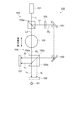
本実施形態の光ポンピング方式の磁場計測装置について、図1を参照して説明する。図1は第1実施形態の磁場計測装置の構成を示す概略図である。
図1に示すように、本実施形態の磁場計測装置100は、直線偏光を照射する光照射手段としてのレーザー光照射装置101と、ガスセル102と、第1光学手段としての無偏光ビームスプリッター103と、第2光学手段としての偏光ビームスプリッター104と、第3光学手段としての光学フィルター105と、入射した光の強度を検出する第1検出部としてのフォトディテクタ(PD)106と、同じく入射した光の強度を検出する第2検出部としてのフォトディテクタ(PD)107と、ミラー108と、を備えている。磁場源M1は、例えば人体のうち脳や心臓などの臓器であって、ミラー108を挟んでガスセル102の近傍に配置される。
(First embodiment)
<Magnetic field measuring device>
The optical pumping type magnetic field measuring apparatus of this embodiment will be described with reference to FIG. FIG. 1 is a schematic diagram showing the configuration of the magnetic field measurement apparatus according to the first embodiment.
As shown in FIG. 1, a magnetic
ガスセル102は、光を透過可能な透明な例えばガラスなどの容器であって、入射した光によって励起(ポンピング)されるアルカリ金属原子がガスセル102の内部に気体の状態で封入されている。アルカリ金属原子としては、カリウム(K)、セシウム(Cs)、ルビジウム(Rb)などが挙げられ、本実施形態では、他のアルカリ金属原子よりも融点が低く、融点がおよそ29℃のセシウムが用いられている。なお、図1ではガスセル102の形状を球状として表したが、ガスセル102の形状はこれに限定されるものでなく、例えば直方体であってもよい。
The
レーザー光照射装置101は、アルカリ金属原子(セシウム)を励起可能な波長範囲の直線偏光であるレーザー光Lをガスセル102に向かって照射可能となっている。具体的には、アルカリ金属原子におけるD1線の超微細構造量子数FがF−1=F’の状態に遷移するように、レーザー光Lを調整する。
The laser
レーザー光照射装置101とガスセル102との間の光軸上に配置された無偏光ビームスプリッター103は、例えば2つの直角プリズムが接合されたものであって、入射したレーザー光Lをプローブ光Lpと参照光Lrとに分岐するプリズム界面103aを有している。プリズム界面103aには、例えば屈折率が異なる誘電体膜が積層された誘電体多層膜が形成されており、プリズム界面103aに入射して誘電体多層膜を透過した光がプローブ光Lpとなり、プリズム界面103aに入射して誘電体多層膜により反射した光が参照光Lrとなる。無偏光ビームスプリッター103において、透過光であるプローブ光Lpの強度、及び反射光である参照光Lrの強度は、入射光であるレーザー光Lの強度に対して半分となっている。言い換えれば、入射したレーザー光Lの強度に対して、プローブ光Lp及び参照光Lrの強度がレーザー光Lの波長範囲においてそれぞれ半分となるように、プリズム界面103aに誘電体多層膜が形成されている。プリズム界面103aに形成される光学的な膜は、誘電体多層膜に限定されず、光透過性及び光反射性を兼ね備えた金属膜や、誘電体多層膜と該金属膜とが組み合わされたものであってもよい。
The
プローブ光Lpは、ガスセル102に入射して透過し、ガスセル102と磁場源M1との間に配置されたミラー108によって反射され、再びガスセル102に入射する。ミラー108は、例えば、アルミニウム(Al)や銀(Ag)、あるいはこれらの合金などの非磁性金属材料からなる。ミラー108が非磁性であることから、ガスセル102と磁場源M1との間にミラー108が配置されても、磁場源M1の磁場計測に影響を及ぼさない。
The probe light Lp is incident on and transmitted through the
ミラー108で反射して再びガスセル102を透過したプローブ光Lpは偏光ビームスプリッター104に入射する。偏光ビームスプリッター104は、例えば2つの直角プリズムが接合されたものであって、プローブ光Lpが入射する第1面104aと、第1面104aに隣り合い、参照光Lrが入射する第2面104bと、直角プリズム同士の接合面であるプリズム界面104cとを有している。プリズム界面104cには、入射した直線偏光を後述するp波とs波とに分離する分離膜が設けられている。該分離膜は、例えば屈折率が異なる誘電体多層膜や、誘電体多層膜と光透過性及び光反射性を兼ね備えた金属膜とを組み合わせたものが挙げられる。
The probe light Lp reflected by the
直線偏光であるプローブ光Lpが、第1面104aからプリズム界面104cに所定の偏光面方向で入射するように、ガスセル102に対して偏光ビームスプリッター104が配置されている。偏光ビームスプリッター104に入射したプローブ光Lpは、偏光ビームスプリッター104を透過するp波(p偏光成分)と、プリズム界面104cで反射するs波(s偏光成分)とに分岐する。p波及びs波も直線偏光であって、p波の直線偏光面は、プリズム界面104cの入射面と平行となっている。s波の直線偏光面は、p波の直線偏光面と直交している。
The
同じく直線偏光である参照光Lrが、第2面104bからプリズム界面104cに所定の偏光面方向で入射するように、偏光ビームスプリッター104に対して無偏光ビームスプリッター103が配置されている。偏光ビームスプリッター104に入射した参照光Lrもまた、偏光ビームスプリッター104を透過するp波と、プリズム界面104cで反射するs波とに分岐する。
The
以降の説明のため、偏光ビームスプリッター104によって分岐されたプローブ光Lpのp波をp1波と呼び、s波をs1波と呼ぶ。また、偏光ビームスプリッター104によって分岐された参照光Lrのp波をp2波と呼び、s波をs2波と呼ぶ。
For the following explanation, the p wave of the probe light Lp branched by the
偏光ビームスプリッター104に対して、p1波とs2波とが入射する位置にPD106が配置される。また、偏光ビームスプリッター104に対して、p2波とs1波とが入射する位置にPD107が配置される。つまり、PD106には、偏光ビームスプリッター104におけるプローブ光Lpの透過光であるp1波と、偏光ビームスプリッター104における参照光Lrの反射光であるs2波とが入射する。PD107には、偏光ビームスプリッター104における参照光Lrの透過光であるp2波と、偏光ビームスプリッター104におけるプローブ光Lpの反射光であるs1波とが入射する。
The
ガスセル102を透過してミラー108で反射し再びガスセル102を透過したプローブ光Lpの強度は、ガスセル102を少なくとも2回透過することにより、無偏光ビームスプリッター103を透過した時点に比べて低下する。それゆえに、本実施形態では、偏光ビームスプリッター104の第1面104aに入射するプローブ光Lpの強度W1と、偏光ビームスプリッター104の第2面104bに入射する参照光Lrの強度W2とが同等となるように、無偏光ビームスプリッター103の参照光Lrの射出側と、偏光ビームスプリッター104の第2面104bとの間に、参照光Lrの強度を低下させる光学フィルター105が設けられている。
The intensity of the probe light Lp that has passed through the
光学フィルター105としては、例えばND(Neutral Density)フィルター(減光フィルター)などを挙げることができる。
Examples of the
無偏光ビームスプリッター103を配置して参照光Lrを発生させる点と、発生させた参照光Lrの強度を低下させる光学フィルター105を設ける点とについての技術的な説明については後述する。
A technical description of the point where the
本実施形態の磁場計測装置100は、上述したように、光ポンピング方式の磁場計測装置であって、プローブ光Lpが、ガスセル102に封入されたアルカリ金属原子を励起させるポンプ光を兼ねるものである。
As described above, the magnetic
また、ミラー108を設けることにより、プローブ光Lpが少なくとも2回ガスセル102を透過するため、ミラー108を設けない場合(後述する第2実施形態にて説明)に比べて、高感度な磁場計測装置100を実現できる。
Also, since the
なお、図1には図示していないが、磁場計測装置100は、レーザー光照射装置101とガスセル102との間のレーザー光Lの光軸上に、第1光学手段の一例である無偏光ビームスプリッター103を適正な位置に配置するための第1位置決め手段と、ガスセル102とPD106との間のプローブ光Lpの光軸上に第2光学手段の一例である偏光ビームスプリッター104を適正な位置に配置するための第2位置決め手段とを備えることが好ましい。
Although not shown in FIG. 1, the magnetic
<磁場測定の原理>
本実施形態の磁場測定の原理について、図1〜図3を参照して説明する。図2は原子スピンのアライメント状態を示す図、図3は直線偏光の偏光面の回転を示す図である。
<Principle of magnetic field measurement>
The principle of magnetic field measurement according to this embodiment will be described with reference to FIGS. FIG. 2 is a diagram illustrating an alignment state of atomic spins, and FIG. 3 is a diagram illustrating rotation of a polarization plane of linearly polarized light.
図1のレーザー光照射装置101と無偏光ビームスプリッター103との間の光軸に沿った方向から見て、図2に示すように偏光面が45度(π/4ラジアン)回転した状態で直線偏光が照射されるようにレーザー光照射装置101が設置される。これにより、無偏光ビームスプリッター103によって分岐されたプローブ光Lpの偏光面もまた光軸に沿った方向から見て45度回転した状態でガスセル102に入射する。
As seen from the direction along the optical axis between the laser
ガスセル102に封入されたガス状のアルカリ金属原子は、ポンプ光を兼ねるプローブ光Lpが照射されることにより励起され、原子スピンがほぼ反平行(逆方向)に向いたアルカリ金属原子がほぼ同数混在する状態となる。この状態はアライメントと呼ばれ、原子スピンは、図2に示すように一方の端が連結された2つの楕円に似た形状となる。図1において磁場源M1がない、すなわち磁場が印加されない場合は、図2に示すように、直線偏光であるプローブ光Lpの振動方向と、原子スピンのアライメント方位とが一致する。
Gaseous alkali metal atoms sealed in the
上述したように、ガスセル102を透過したプローブ光Lpは、偏光ビームスプリッター104によってp1波とs1波とに分岐される。プローブ光Lpの強度をA、p1波の振幅をP、s1波の振幅をS、さらにs1波の強度S2とp1波の強度P2との差をVとすると、磁場が印加されないゼロ磁場の場合、プローブ光Lpの偏光面が回転しないことから、このときのP、S、Vは、以下の数式(1)〜数式(3)で示される。
As described above, the probe light Lp transmitted through the

![]()
![]()
次に、磁場源M1が配置され、ガスセル102に磁場が印加されると、ガスセル102中のアルカリ金属原子の原子スピンが磁場の影響を受け、磁場方向を回転軸として回転する歳差運動を始めることからアライメント方位が変化する。このとき、原子スピンのアライメント方位は、プローブ光Lpの光ポンピングの作用と、光ポンピングの緩和の作用とが働いて方位が一定な定常状態となる。ガスセル102に入射した直線偏光であるプローブ光Lpは、原子スピンのアライメントの影響を受け、印加された磁場の強度に応じて偏光面が回転してガスセル102から射出される。
Next, when the magnetic field source M1 is arranged and a magnetic field is applied to the
例えば、図3に示すように、プローブ光Lpの偏光面(図3に破線で示した)の角度が、45度から反時計回りに+θ(反時計回りを「+」とする)回転した場合(図3で実線で示した)を想定すると、このときのP、Sは以下の数式(4)、数式(5)によって導かれる。 For example, as shown in FIG. 3, when the angle of the polarization plane of probe light Lp (shown by a broken line in FIG. 3) is rotated from 45 degrees counterclockwise by + θ (counterclockwise is “+”) Assuming (shown by a solid line in FIG. 3), P and S at this time are derived by the following equations (4) and (5).
数式(4)を展開すれば以下の数式(6)となり、数式(5)を展開すれば以下の数式(7)となる。 If formula (4) is expanded, the following formula (6) is obtained, and if formula (5) is expanded, the following formula (7) is obtained.
したがって、このときのVは以下の数式(8)で示される。 Therefore, V at this time is expressed by the following formula (8).
次に、上記のように、プローブ光Lpの偏光面が+θ回転した場合に対して、印加される磁場の向きが逆方向になると、プローブ光Lpの偏光面は時計回りに−θ回転することになる。よって、このときのP,S,Vは以下の数式(9)〜数式(11)で示される。 Next, as described above, when the polarization plane of the probe light Lp rotates + θ, the polarization plane of the probe light Lp rotates −θ clockwise when the direction of the applied magnetic field is reversed. become. Therefore, P, S, and V at this time are represented by the following formulas (9) to (11).
上述した磁場測定の原理では、レーザー光Lの照射方向に磁場方向が向いていることを前提としている。一方で、図1に示した磁場計測装置100は、ガスセル102を透過したプローブ光Lpを反射するミラー108を備えている。ガスセル102を透過したプローブ光Lpはミラー108の法線に対して入射角βでミラー108に入射する。ミラー108で反射したプローブ光Lpはミラー108の法線に対して反射角βで反射する。実際には、入射角β及び反射角βが3度〜10度の範囲内となるように、各構成が配置されている。
したがって、本実施形態の磁場計測装置100においては、レーザー光Lの照射方向と磁場方向とが厳密には合致していないが、入射角β及び反射角βが小さい角度となっているので、磁場計測装置100における磁場の受感方向をミラー108の法線方向(図1に矢印で示す方向)としている。
The above-described principle of magnetic field measurement is based on the premise that the magnetic field direction is directed to the irradiation direction of the laser light L. On the other hand, the magnetic
Therefore, in the magnetic
微小な磁場の強度を測定可能な光ポンピング方式の磁場計測装置100は、地磁気や周辺環境から発する磁場などの外部磁場(外部磁場ノイズ)の影響を取り除いて磁場の測定を行うことが好ましい。本実施形態では、図1に示していないものの、磁場計測装置100は、外部磁場の影響を受け難くした磁気シールドルーム内に配置される。あるいは、磁場計測装置100のうち少なくともガスセル102が均一な磁場環境に配置される。均一な磁場環境を生じさせる手段として例えばヘルムホルツコイルなどが用いられ、外部磁場を打ち消す磁場を発生させたヘルムホルツコイルの中心にガスセル102を配置する方法が挙げられる。
The optical pumping type magnetic
一方で、磁場の測定に影響を及ぼすのは外部磁場だけでない。例えば、レーザー光Lは、偏光保持光ファイバーを用いてレーザー発振器からレーザー光照射装置101の射出口に導かれて照射される。レーザー光Lには、偏光保持光ファイバーの振動や、レーザー光Lが照射された空間における空気の振動などによる直線偏光回転ノイズを含む光学ノイズが含まれるおそれがある。とりわけ、偏光保持光ファイバーの振動を防止するために、偏光保持光ファイバーの筐体に対する固定を強化すると、固定された筐体からの振動を受け易くなったり、周囲の温度変化に影響されて膨張収縮し易くなったりして、新たな直線偏光回転ノイズを発生させてしまうという課題があった。
On the other hand, it is not only the external magnetic field that affects the measurement of the magnetic field. For example, the laser beam L is guided and irradiated from the laser oscillator to the exit of the laser
本実施形態の磁場計測装置100は、上記光学ノイズの影響を低減するために、レーザー光Lをプローブ光Lpと参照光Lrとに分岐する無偏光ビームスプリッター103と、ガスセル102を透過した後のプローブ光Lpの強度に対して参照光Lrの強度を同等とするための光学フィルター105と、を備え、光学フィルター105を透過した後の参照光Lrを偏光ビームスプリッター104に入射させてp2波とs2波とに分岐させ、s2波をPD106に入射させ、p2波をPD107に入射させる構成としている。以降、上記光学ノイズを低減する方法について、数式を示して具体的に説明する。
In order to reduce the influence of the optical noise, the magnetic
ここでは、外部磁場(外部磁場ノイズ)の影響が取り除かれて、上記光学ノイズが存在する状態を前提として説明する。先に説明した磁場測定の原理において、図3に示したθは、上記光学ノイズが存在する状態では、磁場源M1の磁場により偏光面が回転した回転角度α(以降、本来の回転角度αと呼ぶ)と、レーザー光L(プローブ光Lp)の直線偏光回転ノイズにより偏光面が回転した回転角度ω(以降、直線偏光回転ノイズの回転角度ωと呼ぶ)とを含んでいることになる。回転角度α及び回転角度ωはそれぞれ回転方向に起因して+(プラス)と−(マイナス)とがある。したがって、回転方向を考慮すると、回転角度αと回転角度ωの組み合わせは4つ存在する。 Here, the description will be made on the assumption that the influence of the external magnetic field (external magnetic field noise) is removed and the optical noise is present. In the principle of magnetic field measurement described above, θ shown in FIG. 3 is the rotation angle α (hereinafter referred to as the original rotation angle α) in which the polarization plane is rotated by the magnetic field of the magnetic field source M1 in the presence of the optical noise. And the rotation angle ω (hereinafter referred to as the rotation angle ω of the linearly polarized light rotation noise) in which the polarization plane is rotated by the linearly polarized light rotation noise of the laser light L (probe light Lp). The rotation angle α and the rotation angle ω are + (plus) and − (minus) due to the rotation direction, respectively. Therefore, considering the rotation direction, there are four combinations of the rotation angle α and the rotation angle ω.
本来の回転角度を+α、直線偏光回転ノイズの回転角度を+ωとすると、図3に示したθは、θ=α+ωとなる。ガスセル102を透過した後のプローブ光Lpの強度をW1とし、光学フィルター105を透過した後の参照光Lrの強度をW2とすると、W1=W2=Wとなっている。したがって、これを磁場測定の原理における数式(4)、数式(5)に当てはめることで、偏光ビームスプリッター104のプローブ光Lpの透過光(透過成分)であるp1波の強度をP1 2とし、偏光ビームスプリッター104のプローブ光Lpの反射光(反射成分)であるs1波の強度をS1 2とすると、P1 2、S1 2は、以下の数式(12)、数式(13)によって導かれる。
If the original rotation angle is + α and the rotation angle of the linearly polarized light rotation noise is + ω, θ shown in FIG. 3 is θ = α + ω. If the intensity of the probe light Lp after passing through the
同じく、偏光ビームスプリッター104の参照光Lrの透過光(透過成分)であるp2波の強度をP2 2とし、偏光ビームスプリッター104の参照光Lrの反射光(反射成分)であるs2波の強度をS2 2とすると、p2波及びs2波は磁場源M1の磁場の影響を受けずに、直線偏光回転ノイズの影響を受けることから、P2 2、S2 2は、以下の数式(14)、数式(15)によって導かれる。
Similarly, the intensity of the p 2 wave that is the transmitted light (transmitted component) of the reference light Lr of the
図1に示すように、PD106には、p1波とs2波とが入射することから、PD106に入射する直線偏光の強度をP3 2とすると、P3 2=P1 2+S2 2となる。また、PD107には、s1波とp2波が入射することから、PD107に入射する直線偏光の強度をS3 2とすると、S3 2=S1 2+P2 2となる。すなわち、P3 2、S3 2は、以下の数式(16)、数式(17)によって導かれる。
As shown in FIG. 1, the
したがって、この場合のS3 2とP3 2との差をV1とすると、V1は以下の数式(18)によって導かれる。 Therefore, if the difference between S 3 2 and P 3 2 in this case is V 1 , V 1 is derived by the following formula (18).
回転角度ωは、非常に小さな値でありα≫2ωであることから、ω≒0とすることができる。したがって、上記数式(18)にω≒0を当てはめると以下の数式(19)となる。 Since the rotation angle ω is a very small value and α >> 2ω, ω≈0 can be set. Therefore, when ω≈0 is applied to the above equation (18), the following equation (19) is obtained.
ガスセル102を透過しない参照光Lrを偏光ビームスプリッター104に入射させて分岐し、分岐したs2波をPD106へ入射させ、分岐したp2波をPD107に入射させることで、PD106とPD107とに入射した直線偏光の強度の差V1を求めると、V1は本来の回転角度αの正弦値として得られる。つまり、直線偏光回転ノイズの回転角度ωの影響が除かれ、本来の回転角度αに基づく磁場の測定が可能となる。
The reference light Lr that does not pass through the
上記第1実施形態の磁場計測装置100は、レーザー光照射装置101から照射されたレーザー光Lをプローブ光Lpと参照光Lrとに分岐する無偏光ビームスプリッター103と、ガスセル102を透過したプローブ光Lpの強度に対して参照光Lrの強度を同等とする光学フィルター105とを備えている。このような磁場計測装置100によれば、ガスセル102を透過したプローブ光Lpを偏光ビームスプリッター104に入射させて分岐し、分岐したp1波をPD106へ入射させ、分岐したs1波をPD107に入射させる。また、ガスセル102を透過しない参照光Lrを偏光ビームスプリッター104に入射させて分岐し、分岐したs2波をPD106へ入射させ、分岐したp2波をPD107に入射させる。PD106とPD107とに入射した直線偏光の強度の差V1を求めると、直線偏光であるプローブ光Lpに直線偏光回転ノイズが含まれていても、V1は本来の回転角度αの正弦値として得られる。つまり、直線偏光回転ノイズの回転角度ωの影響が除かれ、本来の回転角度αに基づく磁場の測定が可能となり、直線偏光回転ノイズを含む光学ノイズを低減して、精度よく磁場源M1の磁場を測定することができる。
The magnetic
(第2実施形態)
次に、第2実施形態の磁場計測装置について、図4を参照して説明する。図4は第2実施形態の磁場計測装置の構成を示す概略図である。第2実施形態の磁場計測装置は、上記第1実施形態の磁場計測装置100に対して、プローブ光Lpがガスセル102を1回透過した後に、第2光学手段である偏光ビームスプリッター104に入射する構成としたものである。したがって、上記第1実施形態の磁場計測装置100と同じ構成には同じ符号を付して詳細な説明は省略する。
(Second Embodiment)
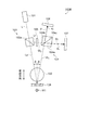
Next, the magnetic field measurement apparatus according to the second embodiment will be described with reference to FIG. FIG. 4 is a schematic diagram showing the configuration of the magnetic field measurement apparatus according to the second embodiment. In the magnetic field measurement apparatus of the second embodiment, the probe light Lp passes through the
図4に示すように、本実施形態の磁場計測装置150は、直線偏光を照射する光照射手段としてのレーザー光照射装置101と、ガスセル102と、第1光学手段としての無偏光ビームスプリッター103と、第2光学手段としての偏光ビームスプリッター104と、第3光学手段としての光学フィルター105と、第1検出部としてのPD106と、第2検出部としてのPD107と、2つの非磁性のミラー151,152と、を備えている。
As shown in FIG. 4, the magnetic
レーザー光照射装置101と磁場源M1とを結ぶ光軸上(直線上)に、無偏光ビームスプリッター103、ガスセル102、偏光ビームスプリッター104がこの順で並ぶように配置されている。
A
レーザー光照射装置101から照射されたレーザー光Lは、無偏光ビームスプリッター103のプリズム界面103aに入射し、光軸に沿って無偏光ビームスプリッター103を透過するプローブ光Lpと、プリズム界面103aで光軸に対して直交する方向に反射する参照光Lrとに分岐される。
The laser light L emitted from the laser
無偏光ビームスプリッター103を透過したプローブ光Lpは、ガスセル102に入射し、ガスセル102を1回透過した後に、偏光ビームスプリッター104の第1面104aに入射する。一方、無偏光ビームスプリッター103で反射した参照光Lrは、光学フィルター105を透過した後に、ミラー151とミラー152とによって反射して、偏光ビームスプリッター104の第2面104bに入射する。
The probe light Lp that has passed through the
第1面104aからプリズム界面104cに入射した直線偏光であるプローブ光Lpは、偏光ビームスプリッター104を光軸に沿って透過するp1波と、プリズム界面104cで反射するs1波とに分岐される。p1波は、光軸に沿って進行してPD106に入射する。s1波は、プリズム界面104cで光軸に対して直交する方向に反射してPD107に入射する。
The probe light Lp, which is linearly polarized light that has entered the
第2面104bからプリズム界面104cに入射した直線偏光である参照光Lrは、光軸に対して直交する方向に偏光ビームスプリッター104を透過するp2波と、プリズム界面104cで光軸に沿った方向に反射するs2波とに分岐される。p2波は、光軸に直交する方向に沿って進行してPD107に入射する。s2波は、プリズム界面104cで光軸に沿った方向に反射してPD106に入射する。すなわち、PD106には、p1波とs2波とが入射し、PD107にはs1波とp2波とが入射する。
Reference light Lr is linearly polarized light incident from the
本実施形態の磁場計測装置150では、ガスセル102に対するレーザー光Lの照射方向と、磁場源M1の磁場方向とが合致しており、上述した磁場測定の原理を的確に当てはめることができる。また、ガスセル102を透過しない参照光Lrを偏光ビームスプリッター104の第2面104bから入射させてp2波とs2波とに分岐させて、s2波をPD106に入射させ、p2波をPD107に入射させる。したがって、上記第1実施形態と同様に、プローブ光Lpに含まれる直線偏光回転ノイズを除いて、本来のプローブ光Lpの回転角度αに基づいて、磁場源M1の磁場強度を精度よく測定することができる。なお、偏光ビームスプリッター104に入射する参照光Lrの強度は、参照光Lrが光学フィルター105を透過することで、ガスセル102を透過した後に偏光ビームスプリッター104に入射するプローブ光Lpの強度と同等となるように調整される。
In the magnetic
上記第1実施形態の磁場計測装置100では、プローブ光Lpがガスセル102を少なくとも2回透過する構成とすることで、本実施形態の磁場計測装置150よりも高感度に磁場源M1の磁場強度を測定可能である。一方で、上記第1実施形態の磁場計測装置100において、無偏光ビームスプリッター103により分岐された参照光Lrを的確に偏光ビームスプリッター104の第2面104bに入射させるには、無偏光ビームスプリッター103と偏光ビームスプリッター104との相対的な位置を精度よく調整する必要がある。これに対して、本実施形態の磁場計測装置150は、ガスセル102を挟んで無偏光ビームスプリッター103と偏光ビームスプリッター104とを直線上に配置すればよいことから、相対的な位置の調整が容易である。
In the magnetic
上記第1実施形態の磁場計測装置100は、ガスセル102に対して、磁場源M1を近くに配置することができる点において、磁場強度の測定上、本実施形態の磁場計測装置150よりも優れている。本実施形態の磁場計測装置150では、ガスセル102と磁場源M1との間に、偏光ビームスプリッター104と、PD106とが配置されることから、磁場強度の測定に影響を及ぼさないように、PD106は非磁性であることが好ましい。
The magnetic
また、本実施形態の磁場計測装置150において、光学フィルターの符号は、上記第1実施形態の磁場計測装置100と同じ符号105を用いたが、実際には、上記第1実施形態の磁場計測装置100では、プローブ光Lpがガスセル102を少なくとも2回透過することから、ガスセル102を透過した後のプローブ光Lpの強度は、本実施形態の磁場計測装置150に比べて上記第1実施形態の磁場計測装置100の方が低下する。したがって、第2光学手段としての偏光ビームスプリッター104にプローブ光Lpと参照光Lrとを強度が同等な状態で入射させるには、第3光学手段としての光学フィルター105は、光の透過率を変化させることが可能な構成であることが好ましい。
In the magnetic
(第3実施形態)
次に、第3実施形態の磁場計測装置について、図5を参照して説明する。図5は第3実施形態の磁場計測装置の構成を示す概略図である。第3実施形態の磁場計測装置は、上記第1実施形態の磁場計測装置100と同じ構成を有するものであるが、無偏光ビームスプリッター103と偏光ビームスプリッター104との相対的な位置関係を異ならせたものである。したがって、上記第1実施形態の磁場計測装置100と同じ構成には同じ符号を付して、詳細な説明は省略する。
(Third embodiment)
Next, a magnetic field measurement apparatus according to a third embodiment will be described with reference to FIG. FIG. 5 is a schematic diagram showing the configuration of the magnetic field measurement apparatus according to the third embodiment. The magnetic field measurement apparatus according to the third embodiment has the same configuration as the magnetic
図5に示すように、本実施形態の磁場計測装置100Bは、直線偏光を照射する光照射手段としてのレーザー光照射装置101と、ガスセル102と、第1光学手段としての無偏光ビームスプリッター103と、第2光学手段としての偏光ビームスプリッター104と、第3光学手段としての光学フィルター105と、入射した光の強度を検出する第1検出部としてのフォトディテクタ(PD)106と、同じく入射した光の強度を検出する第2検出部としてのフォトディテクタ(PD)107と、ミラー108と、を備えている。
As shown in FIG. 5, the magnetic
レーザー光照射装置101から照射され、無偏光ビームスプリッター103に入射したレーザー光Lは、プローブ光Lpと参照光Lrとに分岐される。無偏光ビームスプリッター103を透過したプローブ光Lpは、受感方向に対して入射角度βでガスセル102に入射する。磁場源M1とガスセル102との間にミラー108が配置されていることから、ガスセル102を透過したプローブ光Lpは、ミラー108によって反射され、再びガスセル102に入射する。すなわち、プローブ光Lpは、ガスセル102を2回透過する。
The laser light L emitted from the laser
ガスセル102を2回透過したプローブ光Lpは、偏光ビームスプリッター104に入射する。偏光ビームスプリッター104に入射したプローブ光Lpは、p1波とs1波とに分岐され、p1波は偏光ビームスプリッター104を透過してPD106に入射する。s1波は偏光ビームスプリッター104のプリズム界面104cで反射されてPD107に入射する。
The probe light Lp that has passed through the
一方、無偏光ビームスプリッター103のプリズム界面103aで反射した参照光Lrは、光学フィルター105を透過した後に、偏光ビームスプリッター104の第2面104bに入射する。光学フィルター105を透過した参照光Lrの強度W2は、偏光ビームスプリッター104の第1面104aに入射する直前のプローブ光Lpの強度W1とほぼ同等となっている。
On the other hand, the reference light Lr reflected by the
偏光ビームスプリッター104に入射した参照光Lrは、偏光ビームスプリッター104を透過するp2波と、偏光ビームスプリッター104のプリズム界面104cで反射したs2波とに分岐される。p2波はPD107に入射し、s2波はPD106に入射する。
The reference light Lr incident on the
本実施形態では、PD106に入射するp1波の光軸とs2波の光軸とが同じであると共に、p1波の位相とs2波の位相とが同じになっている。また、PD107に入射するp2波の光軸とs1波の光軸とが同じであると共に、p2波の位相とs1波の位相とが同じになっている。言い換えれば、PD106に入射するp1波とs2波とにおいて、その光軸と位相とが同じになるように、またPD107に入射するp2波とs1波とにおいて、その光軸と位相とが同じになるように、無偏光ビームスプリッター103と偏光ビームスプリッター104とがレーザー光L(プローブ光Lp)の光軸上に配置されている。
In the present embodiment, the optical axis of the p 1 wave incident on the
次に、このような磁場計測装置100Bにおけるレーザー光Lが照射された空間の空気の振動などによる直線偏光回転ノイズを含む光学ノイズの低減方法について、数式(20)〜数式(27)を参照して説明する。
Next, with respect to a method for reducing optical noise including linearly polarized light rotation noise due to vibration of air in the space irradiated with the laser light L in the magnetic
上記第1実施形態で説明したように、磁場測定における本来の回転角度をαとし、直線偏光回転ノイズの回転角度をωとすると、図3に示したθはθ=α+ωとなる。これを上記第1実施形態で説明した磁場測定の原理における数式(6)、数式(7)に当てはめると、p1波の振幅P1、s1波の振幅S1、p2波の振幅P2、s2波の振幅S2は、以下の数式(20)〜数式(23)によって導かれる。 As described in the first embodiment, when the original rotation angle in the magnetic field measurement is α and the rotation angle of the linearly polarized light rotation noise is ω, θ shown in FIG. 3 is θ = α + ω. When this is applied to the equations (6) and (7) in the magnetic field measurement principle described in the first embodiment, the amplitude P 1 of the p 1 wave, the amplitude S 1 of the s 1 wave, and the amplitude P of the p 2 wave The amplitude S 2 of the 2 and s 2 waves is derived by the following formulas (20) to (23).
PD106に入射した直線偏光の振幅P4は、P4=P1+S2であり、PD107に入射した直線偏光の振幅S4は、S4=S1+P2であることから、P4、S4は以下の数式(24)、数式(25)で導かれる。
Since the amplitude P 4 of the linearly polarized light incident on the
この場合のPD107に入射した直線偏光の強度であるS4 2と、PD106に入射した直線偏光の強度であるP4 2との差をU1とすると、U1は、以下の数式(26)で導かれる。
In this case, assuming that the difference between S 4 2 that is the intensity of the linearly polarized light incident on the
上記第1実施形態において説明したように、本来の回転角度αと直線偏光回転ノイズの回転角度ωとの関係は、α≫2ωであり、且つ、αの値も極小さいものとして(α+2ω)≒0として近似することが可能であることから、数式(26)に(α+2ω)≒0を適用すると、以下の数式(27)が導かれる。 As described in the first embodiment, the relationship between the original rotation angle α and the rotation angle ω of the linearly polarized light rotation noise is α >> 2ω and the value of α is also extremely small (α + 2ω) ≈ Since it is possible to approximate as 0, when (α + 2ω) ≈0 is applied to Equation (26), the following Equation (27) is derived.
数式(27)に示すように、本来の回転角度をαとし、直線偏光回転ノイズの回転角度をωとすると、U1は回転角度αの正弦値として得られる。つまり、直線偏光回転ノイズに係る回転角度ωの影響を除いて、本来の回転角度αに基づく磁場の測定が可能となる。 As shown in Equation (27), if the original rotation angle is α and the rotation angle of the linearly polarized light rotation noise is ω, U 1 is obtained as a sine value of the rotation angle α. That is, it is possible to measure the magnetic field based on the original rotation angle α, excluding the influence of the rotation angle ω related to the linearly polarized light rotation noise.
直線偏光回転ノイズに係る回転角度ωの影響が除かれることから、回転角度ωの回転方向(±)は無視できる。また、本来の回転角度αの回転方向(±)に関わらず磁場の測定が可能である。 Since the influence of the rotation angle ω related to the linearly polarized light rotation noise is removed, the rotation direction (±) of the rotation angle ω can be ignored. Further, the magnetic field can be measured regardless of the rotation direction (±) of the original rotation angle α.
上記第3実施形態の磁場計測装置100Bは、レーザー光照射装置101から照射されたレーザー光Lをプローブ光Lpと参照光Lrとに分岐する無偏光ビームスプリッター103と、ガスセル102を透過したプローブ光Lpの強度に対して参照光Lrの強度を同等とする光学フィルター105とを備えている。このような磁場計測装置100Bによれば、ガスセル102を透過したプローブ光Lpを偏光ビームスプリッター104に入射させて分岐し、分岐したp1波をPD106へ入射させ、分岐したs1波をPD107に入射させる。また、ガスセル102を透過しない参照光Lrを偏光ビームスプリッター104に入射させて分岐し、分岐したs2波をPD106へ入射させ、分岐したp2波をPD107に入射させる。また、PD106に入射するp1波とs2波とにおいて、その光軸と位相とが同じになるように、また、PD107に入射するp2波とs1波とにおいて、その光軸と位相とが同じになるように、無偏光ビームスプリッター103と偏光ビームスプリッター104とがレーザー光L(プローブ光Lp)の光軸上に配置されている。したがって、PD106とPD107とに入射した直線偏光の強度の差U1を求めると、直線偏光であるプローブ光Lpに直線偏光回転ノイズが含まれていても、U1は本来の回転角度αの正弦値として表される。つまり、直線偏光回転ノイズの回転角度ωの影響が除かれて、本来の回転角度αに基づく磁場の測定が可能となる。すなわち、直線偏光回転ノイズを含む光学ノイズを低減して、精度よく磁場源M1の磁場を測定することができる。
The magnetic
本発明は、上記した実施形態に限られるものではなく、請求の範囲および明細書全体から読み取れる発明の要旨あるいは思想に反しない範囲で適宜変更可能であり、そのような変更を伴う磁場計測装置もまた本発明の技術的範囲に含まれるものである。上記実施形態以外にも様々な変形例が考えられる。以下、変形例を挙げて説明する。 The present invention is not limited to the above-described embodiment, and can be appropriately changed without departing from the gist or concept of the invention that can be read from the claims and the entire specification, and a magnetic field measurement apparatus with such a change is also included. Moreover, it is included in the technical scope of the present invention. Various modifications other than the above embodiment are conceivable. Hereinafter, a modification will be described.
(変形例1)上記第2実施形態の磁場計測装置150において、非磁性のミラー151,152の配置は、これに限定されない。図6は変形例の磁場計測装置の構成を示す概略図である。例えば、図6に示す変形例の磁場計測装置150Bは、上記第2実施形態の磁場計測装置150に対して、1つの非磁性のミラー151を用いた例を示すものである。具体的には、磁場計測装置150Bは、レーザー光照射装置101と、ガスセル102と、無偏光ビームスプリッター103と、偏光ビームスプリッター104と、光学フィルター105と、PD106と、PD107と、1つの非磁性のミラー151と、を備えている。レーザー光Lは無偏光ビームスプリッター103によってプローブ光Lpと参照光Lrとに分岐される。分岐された参照光Lrは光学フィルター105を透過した後に、ミラー151で反射して、偏光ビームスプリッター104の第2面104bに入射する構成となっている。つまり、分岐された参照光Lrがミラー151に入射するように、レーザー光照射装置101とガスセル102との間の光軸上におけるプリズム界面103aの向きが設定されるよう無偏光ビームスプリッター103を回転させている。変形例の磁場計測装置150Bでは、1つのミラー151を用いているので、複数のミラーを用いる場合に比べて装置構成が簡素化される。なお、非磁性のミラーの数は、1つあるいは2つに限定されず、3つ以上のミラーを用いて参照光Lrを第2面104bに導いてもよい。
(Modification 1) In the magnetic
(変形例2)上記各実施形態の磁場計測装置において、第2光学手段である偏光ビームスプリッター104にプローブ光Lpと参照光Lrとを入射させる光学手段は、非磁性のミラーに限定されない。プローブ光Lp、参照光Lrのそれぞれの光路に例えばプリズムを挿入して、第1面104aにプローブ光Lpを入射させ、第2面104bに参照光Lrを入射させてもよい。
(Modification 2) In the magnetic field measurement apparatus of each of the embodiments described above, the optical means for causing the probe light Lp and the reference light Lr to enter the
100,150…磁場計測装置、101…光照射手段としてのレーザー光照射装置、102…ガスセル、103…第1光学手段としての無偏光ビームスプリッター、104…第2光学手段としての偏光ビームスプリッター、104a…第1面、104b…第2面、105…第3光学手段としての光学フィルター、106…第1検出部としてのフォトディテクタ(PD)、107…第2検出部としてのフォトディテクタ(PD)、108,151,152…非磁性のミラー、Lp…プローブ光、Lr…参照光、M1…磁場源。 DESCRIPTION OF SYMBOLS 100,150 ... Magnetic field measuring apparatus, 101 ... Laser light irradiation apparatus as light irradiation means, 102 ... Gas cell, 103 ... Non-polarizing beam splitter as first optical means, 104 ... Polarizing beam splitter as second optical means, 104a ... First surface, 104b ... Second surface, 105 ... Optical filter as third optical means, 106 ... Photo detector (PD) as first detection unit, 107 ... Photo detector (PD) as second detection unit, 108, 151, 152: Nonmagnetic mirror, Lp: Probe light, Lr: Reference light, M1: Magnetic field source.
Claims (7)
入射した光によって励起されるアルカリ金属原子が充填されるガスセルと、
前記光照射手段と前記ガスセルとの間の光軸上に配置され、入射した前記直線偏光をプローブ光と参照光とに分岐する第1光学手段と、
入射した光の強度を検出する第1検出部及び第2検出部と、
前記ガスセルを透過した前記プローブ光が入射する第1面と、前記参照光が入射する第2面とを有する第2光学手段と、
前記第2光学手段の前記第2面に入射する前記参照光の強度を、前記ガスセルを透過した後の前記プローブ光の強度と同等とする第3光学手段と、を備え、
前記第2光学手段は、前記第1面に入射した前記プローブ光を前記第1検出部と前記第2検出部とに分岐して入射させると共に、前記第2面から入射した前記参照光を前記第1検出部と前記第2検出部とに分岐して入射させることを特徴とする磁場計測装置。 Light irradiation means for irradiating linearly polarized light;
A gas cell filled with alkali metal atoms excited by incident light;
A first optical means disposed on the optical axis between the light irradiation means and the gas cell, and branching the incident linearly polarized light into probe light and reference light;
A first detector and a second detector for detecting the intensity of incident light;
A second optical means having a first surface on which the probe light transmitted through the gas cell is incident and a second surface on which the reference light is incident;
Third optical means for making the intensity of the reference light incident on the second surface of the second optical means equal to the intensity of the probe light after passing through the gas cell;
The second optical means branches the probe light incident on the first surface into the first detection unit and the second detection unit and makes the reference light incident from the second surface enter the first detection unit and the second detection unit. A magnetic field measurement apparatus that branches and enters the first detection unit and the second detection unit.
Priority Applications (1)
| Application Number | Priority Date | Filing Date | Title |
|---|---|---|---|
| JP2016109806A JP2017215225A (en) | 2016-06-01 | 2016-06-01 | Magnetic field measurement device |
Applications Claiming Priority (1)
| Application Number | Priority Date | Filing Date | Title |
|---|---|---|---|
| JP2016109806A JP2017215225A (en) | 2016-06-01 | 2016-06-01 | Magnetic field measurement device |
Publications (2)
| Publication Number | Publication Date |
|---|---|
| JP2017215225A true JP2017215225A (en) | 2017-12-07 |
| JP2017215225A5 JP2017215225A5 (en) | 2019-05-30 |
Family
ID=60575540
Family Applications (1)
| Application Number | Title | Priority Date | Filing Date |
|---|---|---|---|
| JP2016109806A Withdrawn JP2017215225A (en) | 2016-06-01 | 2016-06-01 | Magnetic field measurement device |
Country Status (1)
| Country | Link |
|---|---|
| JP (1) | JP2017215225A (en) |
Cited By (4)
| Publication number | Priority date | Publication date | Assignee | Title |
|---|---|---|---|---|
| CN109521376A (en) * | 2018-11-09 | 2019-03-26 | 中国计量科学研究院 | Atom magnetometer based on miniature atomic air chamber |
| JP2019084102A (en) * | 2017-11-08 | 2019-06-06 | 株式会社大一商会 | Game machine |
| JP2020003270A (en) * | 2018-06-26 | 2020-01-09 | 株式会社リコー | Atomic magnetism sensor, gradiometer, and biomagnetism measuring device |
| CN112557971A (en) * | 2020-12-03 | 2021-03-26 | 中国船舶重工集团有限公司第七一0研究所 | High-sensitivity laser optical pump magnetometer and design method |
-
2016
- 2016-06-01 JP JP2016109806A patent/JP2017215225A/en not_active Withdrawn
Cited By (6)
| Publication number | Priority date | Publication date | Assignee | Title |
|---|---|---|---|---|
| JP2019084102A (en) * | 2017-11-08 | 2019-06-06 | 株式会社大一商会 | Game machine |
| JP2020003270A (en) * | 2018-06-26 | 2020-01-09 | 株式会社リコー | Atomic magnetism sensor, gradiometer, and biomagnetism measuring device |
| CN109521376A (en) * | 2018-11-09 | 2019-03-26 | 中国计量科学研究院 | Atom magnetometer based on miniature atomic air chamber |
| CN109521376B (en) * | 2018-11-09 | 2023-12-15 | 中国计量科学研究院 | Atomic magnetometer based on miniature atomic air chamber |
| CN112557971A (en) * | 2020-12-03 | 2021-03-26 | 中国船舶重工集团有限公司第七一0研究所 | High-sensitivity laser optical pump magnetometer and design method |
| CN112557971B (en) * | 2020-12-03 | 2022-06-03 | 中国船舶重工集团有限公司第七一0研究所 | High-sensitivity laser optical pump magnetometer and design method |
Similar Documents
| Publication | Publication Date | Title |
|---|---|---|
| US9915711B2 (en) | System and method for atom-modulated, low-drift sensor | |
| JP6171355B2 (en) | Magnetic field measuring device | |
| JP6463423B2 (en) | Optical pumping magnetometer | |
| JP5264242B2 (en) | Atomic magnetometer and magnetic force measurement method | |
| US8212556B1 (en) | Atomic magnetometer | |
| US10288701B2 (en) | Optically pumped atomic magnetometer and magnetic sensing method | |
| US10215816B2 (en) | Magnetic field measuring apparatus | |
| JP2016050837A5 (en) | ||
| US20150022200A1 (en) | Optically pumped magnetometer and optical pumping magnetic force measuring method | |
| JP2017215225A (en) | Magnetic field measurement device | |
| JP2012510609A (en) | Miniature optical cell for miniaturized nuclear magnetic resonance gyroscope | |
| JP5849640B2 (en) | Magnetic field measuring device | |
| JP2015143669A (en) | Magnetic field measuring device | |
| JP5874808B2 (en) | Magnetic field measuring device | |
| JP5866940B2 (en) | Magnetic sensor device and magnetic measuring device | |
| KR101809402B1 (en) | Atom spin gyroscope using a single laser beam | |
| JP6880834B2 (en) | Magnetic sensor, biomagnetic measuring device | |
| Cao et al. | Dual-polarization interferometric fiber optic gyroscope based on a four-port circulator | |
| JP5682344B2 (en) | Magnetic measuring device and biological state measuring device | |
| US11808577B2 (en) | Atomic gyroscope and atomic interferometer | |
| JP6024114B2 (en) | Magnetic field measuring device | |
| US10901052B1 (en) | Atomic magnetometer | |
| JP5747556B2 (en) | Magnetic field measuring apparatus and cell array | |
| JP5907234B2 (en) | Magnetic measuring device and biological state measuring device | |
| JP5621240B2 (en) | Magnetic measuring device |
Legal Events
| Date | Code | Title | Description |
|---|---|---|---|
| RD05 | Notification of revocation of power of attorney |
Free format text: JAPANESE INTERMEDIATE CODE: A7425 Effective date: 20180906 |
|
| RD03 | Notification of appointment of power of attorney |
Free format text: JAPANESE INTERMEDIATE CODE: A7423 Effective date: 20181116 |
|
| A521 | Written amendment |
Free format text: JAPANESE INTERMEDIATE CODE: A523 Effective date: 20190412 |
|
| A621 | Written request for application examination |
Free format text: JAPANESE INTERMEDIATE CODE: A621 Effective date: 20190412 |
|
| A761 | Written withdrawal of application |
Free format text: JAPANESE INTERMEDIATE CODE: A761 Effective date: 20191028 |