JP2017211225A - Gas chromatograph device - Google Patents
Gas chromatograph device Download PDFInfo
- Publication number
- JP2017211225A JP2017211225A JP2016103166A JP2016103166A JP2017211225A JP 2017211225 A JP2017211225 A JP 2017211225A JP 2016103166 A JP2016103166 A JP 2016103166A JP 2016103166 A JP2016103166 A JP 2016103166A JP 2017211225 A JP2017211225 A JP 2017211225A
- Authority
- JP
- Japan
- Prior art keywords
- column
- time
- carrier gas
- temperature
- unit
- Prior art date
- Legal status (The legal status is an assumption and is not a legal conclusion. Google has not performed a legal analysis and makes no representation as to the accuracy of the status listed.)
- Granted
Links
Images


Abstract
Description
本発明はガスクロマトグラフ装置に関する。なお、ここでいうガスクロマトグラフ装置は検出器の種類を問わず、当然のことながら、検出器が質量分析装置であるガスクロマトグラフ質量分析装置を含む。 The present invention relates to a gas chromatograph apparatus. In addition, the gas chromatograph apparatus here contains the gas chromatograph mass spectrometer whose detector is a mass spectrometer naturally, regardless of the kind of detector.
一般的なガスクロマトグラフ(以下「GC」と略す)装置では、カラムの入口に設けた試料気化室内で気化させた試料をキャリアガスに乗せてカラムに送り込み、試料に含まれる各種成分をカラムを通過する過程で時間方向に分離する。そして、分離されて順次流出する成分をカラムの出口に設けた検出器により検出し、その検出信号に基づいて、各成分がカラムから流出する時間つまり保持時間と成分濃度に応じた信号強度との関係を示すクロマトグラムを作成する。 In a general gas chromatograph (hereinafter abbreviated as “GC”) device, a sample vaporized in a sample vaporization chamber provided at the inlet of the column is loaded onto a carrier gas and sent to the column, and various components contained in the sample pass through the column. In the process of separating. Then, the components that are separated and flow out sequentially are detected by a detector provided at the outlet of the column, and based on the detection signal, the time during which each component flows out of the column, that is, the retention time and the signal intensity corresponding to the component concentration Create a chromatogram showing the relationship.
GC装置では、通常、カラムを内装したカラムオーブンの温度を室温よりも高い一定温度に維持する恒温分析を行ったり、所定の昇温プログラムに従ってカラムオーブンの温度を上昇させる昇温分析を行ったりするが、カラム内に大気が混入している状態でカラムの温度を上げるとカラム内壁に塗布されている液相が酸化する等、カラムが劣化するおそれがある(例えば特許文献1など参照)。このため、従来のGC装置では、装置停止状態から装置の起動の指示がなされてもすぐにはカラムオーブンの温度を上昇させず、まずキャリアガスをカラム内に送り込むためのガス圧力制御又はガス流量制御のみを開始する。これにより、カラム内のガスがヘリウム、窒素等のキャリアガスに置換される。そして、キャリアガス送給開始時点から所定の起動時待機時間(以下「スタートタイム」という)が経過した時点でカラムオーブンの温度制御を開始してカラムオーブン内を所定の温度にする。 In the GC apparatus, a constant temperature analysis is usually performed in which the temperature of the column oven in which the column is built is maintained at a constant temperature higher than room temperature, or a temperature increase analysis is performed in which the temperature of the column oven is increased according to a predetermined temperature increase program. However, if the temperature of the column is raised while air is mixed in the column, the column may be deteriorated, for example, the liquid phase applied to the inner wall of the column is oxidized (see, for example, Patent Document 1). For this reason, in the conventional GC apparatus, the temperature of the column oven is not immediately increased even if an instruction to start the apparatus is issued from the apparatus stop state, but first the gas pressure control or the gas flow rate for feeding the carrier gas into the column. Start control only. Thereby, the gas in the column is replaced with a carrier gas such as helium or nitrogen. Then, temperature control of the column oven is started when a predetermined start-up waiting time (hereinafter referred to as “start time”) has elapsed from the start of carrier gas supply, and the inside of the column oven is brought to a predetermined temperature.
一方、GC装置の稼働(通電)中に試料気化室の消耗品であるガラスインサートやセプタムを交換できるように、検出器の温度を高温に維持したまま、カラムオーブン及び試料気化室の温度制御とキャリアガスの圧力(又は流量)制御とを停止することができる機能(例えば島津製作所製のGC装置における「INJ保守」機能)を備えたGC装置も知られている。こうした装置では、消耗品の交換後にカラムオーブン及び試料気化室の温度制御とキャリアガスの圧力(又は流量)制御とを再開する必要があるが、その際にもカラム内に大気が混入している可能性があるから、上記装置起動時と同様に、まずキャリアガスの圧力(又は流量)制御のみ再開し、その時点からスタートタイムだけ待ってカラムオーブンの温度制御を開始するようにしている。 On the other hand, the temperature control of the column oven and the sample vaporization chamber can be performed while maintaining the temperature of the detector at a high temperature so that the glass insert and septum, which are consumables of the sample vaporization chamber, can be replaced during operation (energization) of the GC apparatus A GC device having a function capable of stopping the pressure (or flow rate) control of the carrier gas (for example, an “INJ maintenance” function in a GC device manufactured by Shimadzu Corporation) is also known. In such an apparatus, it is necessary to restart the temperature control of the column oven and the sample vaporizing chamber and the pressure (or flow rate) control of the carrier gas after replacement of the consumables, and the atmosphere is mixed in the column at that time as well. Since there is a possibility, only the pressure (or flow rate) control of the carrier gas is restarted first, and the temperature control of the column oven is started after waiting for the start time from that point.
こうした従来のGC装置において、上記スタートタイムはユーザーが手動で設定するか、或いは装置のファームウェアに予め設定された、例えば5分、10分などの規定値が用いられるようになっている。ユーザーがスタートタイムを設定する場合、ユーザーがそのときに使用するキャリアガスの種類やカラム入口圧などの分析条件に基づいて算出されるガス流量の値からカラム内のガスを置換するための所要時間を推算し、その推算値に基づいてスタートタイムを決める場合もあるが、実際にはこうした計算はかなり複雑で面倒である。また、分析条件を変更するとその度に所要時間を計算し直し、スタートタイムの設定を変更する必要があるという手間もある。 In such a conventional GC apparatus, the start time is manually set by the user or a preset value such as 5 minutes or 10 minutes set in advance in the firmware of the apparatus is used. When the user sets the start time, the time required to replace the gas in the column from the gas flow rate value calculated based on the analysis conditions such as the type of carrier gas used at that time and the column inlet pressure In some cases, the start time is determined based on the estimated value, but in reality such calculation is quite complicated and troublesome. In addition, every time the analysis conditions are changed, it is necessary to recalculate the required time and change the start time setting.
また特に最近のGC装置では、例えば誘電体バリア放電イオン化検出器(BID)のようにカラム出口圧が大気圧ではなく検出器の設定条件に応じたガス圧となる検出器がカラム出口に接続されていたり(特許文献2参照)、カラム出口にバックフラッシュ素子を介して検出器が接続されていたり(特許文献3参照)、さらには、複数の分析ラインが並列に設けられていたり(特許文献4参照、非特許文献1参照)、する等、システム構成がかなり複雑になっている。そのため、こうした装置では、個々のユーザーがそのときの分析条件に応じた適切なスタートタイムを設定するのは実質的に不可能であり、ユーザーはカラム内のガスを置換する所要時間を求めることなく、十分な時間的余裕をみてかなり長めのスタートタイムを設定しているのが実状である。 In particular, in a recent GC apparatus, a detector whose column outlet pressure is not an atmospheric pressure but a gas pressure corresponding to a set condition of the detector, such as a dielectric barrier discharge ionization detector (BID), is connected to the column outlet. (See Patent Document 2), a detector is connected to the column outlet via a backflush element (see Patent Document 3), and a plurality of analysis lines are provided in parallel (Patent Document 4). The system configuration is considerably complicated, for example, see Non-Patent Document 1). Therefore, in such a device, it is practically impossible for each user to set an appropriate start time according to the analysis conditions at that time, and the user does not have to calculate the time required to replace the gas in the column. Actually, a fairly long start time is set with a sufficient time margin.
そのため、実際にはカラム内がキャリアガスで満たされていてカラムオーブンの温度を上げても構わないのにも拘わらず待機状態を続け、これがGC分析の効率を低下させる大きな原因となっている。また、無駄に待機している間にもキャリアガスを流し続けるためキャリアガスの消費量が増え、これが測定のランニングコストの増加に繋がるという問題もある。 Therefore, although the column is actually filled with the carrier gas and the temperature of the column oven may be raised, the standby state is continued, which is a major cause of reducing the efficiency of GC analysis. In addition, since the carrier gas continues to flow even while waiting in vain, the amount of consumption of the carrier gas increases, which leads to an increase in the running cost of measurement.
本発明は上記課題に鑑みて成されたものであり、その目的とするところは、装置構成が複雑な場合であっても、ユーザーに負担を掛けることなく且つ無駄な時間待つことなく、装置起動時等にカラム内の残留ガスをキャリアガスで十分に置換したあとにカラムオーブンの温度を上昇させることができるガスクロマトグラフ装置を提供することである。 The present invention has been made in view of the above problems, and the object of the present invention is to start the apparatus without burdening the user and waiting for a useless time even when the apparatus configuration is complicated. An object of the present invention is to provide a gas chromatograph capable of raising the temperature of a column oven after sufficiently replacing the residual gas in the column with a carrier gas.
上記課題を解決するために成された本発明の第1の態様は、カラムと、該カラムが内装されるカラムオーブンと、前記カラムを通過したあとの試料中の成分を検出する検出器と、前記カラムへ供給されるキャリアガスの流量を調整する流量調節部と、前記カラムの入口に設けられ前記流量調節部で調整されたキャリアガスの流れに乗せて試料を該カラムに導入する試料導入部と、を具備するGC装置であって、
a)少なくとも、カラム入口圧及び出口圧、カラムの長さ及び内径、キャリアガスの種類、並びにカラムオーブンの温度に関する情報を収集する情報収集部と、
b)装置起動動作、又は、少なくとも前記カラムオーブンによる温調が停止され若しくは該カラムオーブンが所定の温度に維持され前記流量調節部からカラムへのキャリアガスの供給が停止している状態から分析実行のための定常待機状態に復帰させる装置復帰動作に際し、装置起動動作又は装置復帰動作の開始時点又はそれよりも以前のいずれかの時点で、前記情報収集部により収集された情報に基づいて、カラムに送給されるキャリアガスにより該カラム内のガスが置換されるに要する時間を算出する時間算出部と、
c)装置起動動作又は装置復帰動作の際に、前記流量調節部から前記カラムへのキャリアガスの供給を開始した時点から、前記時間算出部で算出された時間又はそれに所定の余裕を見込んだ時間が経過するまで待って前記カラムオーブンの温度上昇を伴う温度制御を許可する分析制御部と、
を備えることを特徴としている。
The first aspect of the present invention made to solve the above problems includes a column, a column oven in which the column is built, a detector for detecting a component in the sample after passing through the column, A flow rate adjusting unit that adjusts the flow rate of the carrier gas supplied to the column, and a sample introduction unit that introduces the sample into the column by being placed on the flow of the carrier gas provided at the inlet of the column and adjusted by the flow rate adjusting unit A GC device comprising:
a) an information collecting unit for collecting at least information on column inlet pressure and outlet pressure, column length and inner diameter, carrier gas type, and column oven temperature;
b) Analyzing from the apparatus start-up operation, or at least the temperature adjustment by the column oven is stopped, or the column oven is maintained at a predetermined temperature and the supply of the carrier gas from the flow rate controller to the column is stopped. In the device return operation for returning to the steady standby state for the device, the column is based on the information collected by the information collection unit at any time before or before the start of the device start-up operation or the device return operation. A time calculation unit for calculating the time required for the gas in the column to be replaced by the carrier gas fed to
c) The time calculated by the time calculation unit or the time when a predetermined margin is expected from the time when the supply of the carrier gas from the flow rate adjustment unit to the column is started during the device start-up operation or device return operation. An analysis control unit that waits until elapse of time and permits temperature control with a temperature increase of the column oven,
It is characterized by having.
また上記課題を解決するために成された本発明の第2の態様は、カラムと、該カラムが内装されるカラムオーブンと、前記カラムを通過したあとの試料中の成分を検出する検出器と、前記カラムへ供給されるキャリアガスの流量を調整する流量調節部と、前記カラムの入口に設けられ前記流量調節部で調整されたキャリアガスの流れに乗せて試料を該カラムに導入する試料導入部と、を具備するGC装置であって、
a)少なくとも、カラムの出口圧、カラムの長さ及び内径、キャリアガスの種類、及びカラムオーブン温度に関する情報を収集する情報収集部と、
b)装置起動、又は、少なくとも前記カラムオーブンによる温調が停止され若しくは該カラムオーブンが所定の温度に維持され前記流量調節部からカラムへのキャリアガスの供給が停止している状態から分析実行のための定常待機状態に復帰させる装置復帰動作に際し、装置起動動作又は装置復帰動作の開始時点又はそれよりも以前のいずれかの時点で、前記情報収集部により収集された情報に基づいて、カラムに送給されるキャリアガスによりカラム内のガスが置換されるに要する時間が目標値に収まるようなキャリアガスの平均線速度を実現可能であるカラム入口圧を計算する入口圧算出部と、
c)装置起動又は装置復帰動作の際に、前記入口圧算出部で算出されたカラム入口圧の設定の下で前記流量調節部から前記カラムへのキャリアガスの供給を開始した時点から、前記目標値又はそれに所定の余裕を見込んだ時間が経過するまで待って前記カラムオーブンの温度上昇を伴う温度制御を許可する分析制御部と、
を備えることを特徴としている。
A second aspect of the present invention made to solve the above-described problems includes a column, a column oven in which the column is installed, and a detector that detects components in the sample after passing through the column. A flow rate adjusting unit that adjusts the flow rate of the carrier gas supplied to the column, and a sample introduction unit that introduces a sample into the column by being placed on the carrier gas flow provided at the inlet of the column and adjusted by the flow rate adjusting unit A GC device comprising:
a) an information collecting unit for collecting at least information on the outlet pressure of the column, the length and inner diameter of the column, the type of carrier gas, and the column oven temperature;
b) The analysis is started from the state where the apparatus is started or at least the temperature control by the column oven is stopped or the column oven is maintained at a predetermined temperature and the supply of the carrier gas from the flow rate controller to the column is stopped. In response to the device return operation for returning to the steady standby state, the information is collected in the column based on the information collected by the information collecting unit at the start time of the device start-up operation or the device return operation or any time before that. An inlet pressure calculation unit for calculating a column inlet pressure capable of realizing an average linear velocity of the carrier gas so that a time required for replacing the gas in the column with the carrier gas to be fed falls within the target value;
c) At the time of starting the apparatus or returning the apparatus, the target gas from the time when the supply of the carrier gas to the column from the flow rate adjusting unit is started under the setting of the column inlet pressure calculated by the inlet pressure calculating unit. An analysis control unit that waits until a time when a value or a predetermined allowance elapses and permits temperature control with a temperature increase of the column oven;
It is characterized by having.
さらにまた上記課題を解決するために成された本発明の第3の態様は、カラムと、該カラムが内装されるカラムオーブンと、前記カラムを通過したあとの試料中の成分を検出する検出器と、前記カラムへ供給されるキャリアガスの流量を調整する流量調節部と、前記カラムの入口に設けられ前記流量調節部で調整されたキャリアガスの流れに乗せて試料を前記カラムに導入する試料導入部と、を具備するGC装置であって、
a)少なくとも、カラムの入口圧及び出口圧、カラムの長さ及び内径、並びにキャリアガスの種類に関する情報を収集する情報収集部と、
b)前記カラムオーブン内部の温度又はその周囲の温度を検知する温度検知部と、
c)装置起動、又は、少なくとも前記カラムオーブンによる温調が停止され前記流量調節部からカラムへのキャリアガスの供給が停止している状態から分析実行のための定常待機状態に復帰させる装置復帰動作の際に、前記流量調節部から前記カラムへのキャリアガスの供給を開始したあと、前記情報収集部により収集された情報及び前記温度検知部により時間経過に伴って繰り返し検知される温度に基づいて、カラムに送給されたキャリアガスによりすでにキャリアガスに置換されたカラムの長さを計算する置換済み情報算出部と、
d)前記置換済み情報算出部により算出されたカラムの長さに基づきカラム内のガスが十分に置換されたか否かを判定し、十分に置換されたと判定されたあとに前記カラムオーブンの温度上昇を伴う温度制御を許可する分析制御部と、
を備えることを特徴としている。
Furthermore, in order to solve the above-mentioned problems, a third aspect of the present invention includes a column, a column oven in which the column is built, and a detector for detecting a component in the sample after passing through the column. A flow rate adjusting unit that adjusts the flow rate of the carrier gas supplied to the column, and a sample that is provided at the inlet of the column and that is introduced into the column by being placed on the carrier gas flow adjusted by the flow rate adjusting unit A GC device comprising: an introduction unit;
a) an information collecting unit that collects information on at least the inlet and outlet pressures of the column, the length and inner diameter of the column, and the type of carrier gas;
b) a temperature detector for detecting the temperature inside the column oven or the surrounding temperature;
c) Device start-up or device return operation for returning from a state where temperature control by at least the column oven is stopped and supply of carrier gas from the flow rate control unit to the column is stopped to a steady standby state for analysis execution In this case, after starting the supply of the carrier gas from the flow rate adjusting unit to the column, based on the information collected by the information collecting unit and the temperature repeatedly detected over time by the temperature detecting unit A replaced information calculation unit that calculates the length of the column that has already been replaced by the carrier gas by the carrier gas supplied to the column;
d) Determine whether the gas in the column has been sufficiently replaced based on the length of the column calculated by the replaced information calculation unit, and after determining that the gas has been sufficiently replaced, increase the temperature of the column oven An analysis control unit that permits temperature control with
It is characterized by having.
本発明において、上記「少なくとも前記カラムオーブンによる温調が停止され若しくは該カラムオーブンが所定の温度に維持され前記流量調節部からカラムへのキャリアガスの供給が停止している状態から分析実行のための定常待機状態に復帰させる装置復帰動作」とは、例えば上記「INJ保守」機能又はそれに相当する機能における動作である。 In the present invention, the above-mentioned “at least temperature adjustment by the column oven is stopped or the column oven is maintained at a predetermined temperature and the supply of the carrier gas from the flow rate adjusting unit to the column is stopped. The “device return operation for returning to the steady standby state” is, for example, an operation in the “INJ maintenance” function or a function corresponding thereto.
GC装置では一般に、使用するカラムの内径及び長さ、カラムの入口圧及び出口圧、キャリアガスの種類、カラムオーブンの温度(恒温、昇温のプログラムなど)等は、分析に先立って分析条件としてユーザーにより設定され装置内部に記憶される。したがって、本発明に係るGC装置において、上記情報収集部はそうして記憶されている情報から必要な情報を抽出することができる。ただし、カラム出口圧は使用される検出器の種類等にも依存し、検出器によっては大気圧である場合もある。また、検出器が上述したBIDのように検出セル内に他のガスが供給されるタイプのものである場合には、カラム出口圧はそうした検出器における他のガスの流量制御のための設定値により得られる。また、カラム入口圧や出口圧は分析条件の設定値ではなく、その設定値に基づいてガスを実際に供給したときの圧力センサによる実測値でもよい。 In general, the inner diameter and length of the column used, the inlet pressure and outlet pressure of the column, the type of carrier gas, the temperature of the column oven (constant temperature, temperature rising program, etc.), etc. are the analytical conditions prior to analysis. Set by the user and stored inside the device. Therefore, in the GC device according to the present invention, the information collection unit can extract necessary information from the information stored in this manner. However, the column outlet pressure depends on the type of detector used and the like, and may be atmospheric pressure depending on the detector. Further, when the detector is of a type in which other gas is supplied into the detection cell, such as the above-mentioned BID, the column outlet pressure is a set value for controlling the flow rate of the other gas in such a detector. Is obtained. Further, the column inlet pressure and the outlet pressure are not set values of analysis conditions, but may be measured values by a pressure sensor when gas is actually supplied based on the set values.
本発明の第1の態様のGC装置では例えば、ユーザーにより装置起動や装置復帰動作が指示されると、時間算出部が、情報収集部により収集された情報を所定の計算式に適用することにより、流量調節部からカラムに送給されるキャリアガスの平均線速度を計算する。さらに、その平均線速度の下でカラム内のガスがキャリアガスに置換されるに要するガス置換所要時間を算出する。ここでは、カラムオーブン温度は一定であることを前提としているが、カラム内のガスが置換されるまでの間に、カラムオーブンは一定温度(残留ガスによる液相の劣化を引き起こさない温度)に温調されていてもよいし、全く温調されていない状態(ヒータに通電されていない状態)であってもよい。後者の場合には、例えばカラムオーブン内部の温度をモニタする温度センサ又は装置が設置された室内の温度をモニタする温度センサによる検知温度をカラムオーブン温度であるとみなせばよい。 In the GC device according to the first aspect of the present invention, for example, when a device activation or device return operation is instructed by a user, the time calculation unit applies the information collected by the information collection unit to a predetermined calculation formula. The average linear velocity of the carrier gas fed to the column from the flow rate controller is calculated. Further, a gas replacement time required for replacing the gas in the column with the carrier gas under the average linear velocity is calculated. Here, it is assumed that the column oven temperature is constant, but the column oven is kept at a constant temperature (a temperature that does not cause deterioration of the liquid phase due to residual gas) until the gas in the column is replaced. The temperature may be adjusted, or the temperature may not be controlled at all (the heater is not energized). In the latter case, for example, the temperature detected by the temperature sensor that monitors the temperature inside the column oven or the temperature sensor that monitors the temperature inside the room in which the apparatus is installed may be regarded as the column oven temperature.
分析制御部は、流量調節部からカラムへのキャリアガスの供給を開始した時点からタイマによる計時を開始し、その計時が上記ガス置換所要時間又はそれに所定の余裕を見込んだ時間に達したか否かを判定し、計時がその時間に達したならばカラムオーブンの温度上昇を伴う温度制御を許可する。これにより、カラム内の残留ガスがキャリアガスに完全に置換されるまでは、カラムオーブンの温度は少なくとも残留ガスによる液相の劣化を引き起こさない温度に維持され、カラム内の残留ガスがキャリアガスに完全に置換されたあとに大きな遅滞なくカラムオーブンの温度は分析のための初期温度に設定される。 The analysis control unit starts counting by a timer from the time when the supply of the carrier gas to the column from the flow rate adjusting unit is started, and whether or not the time has reached the time required for the gas replacement or the time for which a predetermined margin is expected. If the time reaches that time, temperature control with temperature rise of the column oven is permitted. As a result, until the residual gas in the column is completely replaced with the carrier gas, the temperature of the column oven is maintained at least at a temperature that does not cause deterioration of the liquid phase due to the residual gas, and the residual gas in the column becomes the carrier gas. The column oven temperature is set to the initial temperature for analysis without significant delay after complete replacement.
なお、時間算出部が予めユーザーにより設定された分析条件を利用してガス置換所要時間を算出する場合には、装置起動や装置復帰動作が指示されたあとではなく、それ以前の適宜の時点でガス置換所要時間を算出しておくこともできる。 In addition, when the time calculation unit calculates the gas replacement time using the analysis conditions set in advance by the user, it is not after an instruction to start or return the apparatus but at an appropriate time before that. The time required for gas replacement can also be calculated.
また本発明に係るGC装置の第1の態様において、好ましくは、少なくとも前記カラムが複数並列に設けられ、該複数のカラムが共に分析に使用される場合に、前記時間算出部はカラム内のガスが置換されるに要する時間をカラム毎に計算し、前記分析制御部はカラム毎の前記時間の中で最も長い時間に基づいて前記カラムオーブンの温度制御を許可するタイミングを決める構成とするとよい。 In the first aspect of the GC apparatus according to the present invention, preferably, when at least a plurality of the columns are provided in parallel and the plurality of columns are used for analysis, the time calculation unit is configured to detect the gas in the column. It is preferable that the time required for replacing the column oven is calculated for each column, and the analysis control unit determines the timing for permitting temperature control of the column oven based on the longest time among the times for each column.
並設されている複数のカラムが同時に使用される場合、カラムの内径や長さ、カラム入口圧及び出口圧の相違などによってガス置換所要時間に差異が生じる。これに対し、上記好ましい構成によれば、複数のカラムが同時に使用される場合でも、ガス置換所要時間が最も長いカラム内の残留ガスがキャリアガスに確実に置換されてからカラムオーブンの温度が上昇するので、カラムの液相の劣化を確実に防止することができる。 When a plurality of columns arranged in parallel are used at the same time, the gas replacement time varies depending on the inner diameter and length of the column, the difference between the column inlet pressure and the outlet pressure, and the like. On the other hand, according to the above preferred configuration, even when a plurality of columns are used at the same time, the temperature of the column oven rises after the residual gas in the column having the longest gas replacement time is reliably replaced with the carrier gas. Therefore, deterioration of the liquid phase of the column can be reliably prevented.
また本発明に係るGC装置の第1の態様では、
キャリアガス供給開始時点からカラムオーブン温度制御開始時点までの待機時間をユーザーが入力設定する入力設定部をさらに備え、
前記分析制御部は、前記時間算出部により算出された時間若しくはそれに所定の余裕を見込んだ時間と前記入力設定部により設定された待機時間とのいずれかを選択し、その選択した時間に基づいて前記カラムオーブンの温度制御を許可するタイミングを決める構成としてもよい。
In the first aspect of the GC device according to the present invention,
The apparatus further includes an input setting unit in which a user inputs and sets a waiting time from the carrier gas supply start time to the column oven temperature control start time,
The analysis control unit selects either the time calculated by the time calculation unit or a time allowing a predetermined margin and the standby time set by the input setting unit, and based on the selected time It is good also as a structure which determines the timing which permits the temperature control of the said column oven.
即ち、この構成によれば、カラムオーブンの温度制御を許可するタイミングを決めるのに、自動的に決定される時間とユーザー自身の判断により設定された時間とのいずれを使用するのかを切り替えることができる。それによって、例えば単にカラム内の残留ガスをキャリアガスで置換するためだけでなく、キャリアガスを或る程度の時間流し続けることでカラム内部の洗浄(汚染物質の除去)を行いたいような場合に、自動的に決定される時間よりもかなり長い時間キャリアガスを流し続けることができる。 In other words, according to this configuration, it is possible to switch between the automatically determined time and the time set by the user's own judgment to determine the timing for permitting the temperature control of the column oven. it can. Thereby, for example, not only to replace the residual gas in the column with the carrier gas, but also to clean the inside of the column (removal of contaminants) by keeping the carrier gas flowing for a certain period of time, The carrier gas can continue to flow for a considerably longer time than is automatically determined.
上記本発明の第1の態様のGC装置では、ガス入口圧が決められており所定の計算式によってキャリアガスの平均線速度が計算されていたが、本発明の第2の態様のGC装置では、逆に、ガス置換所要時間に目標値が定められており、それを達成するように平均線速度を調整する。そこで、入口圧算出部は例えば上記所定の計算式を変形した式を用い、ガス置換所要時間が目標値に収まるような平均線速度を得るためのガス入口圧を算出する。そして分析制御部は、ガス入口圧をこの計算で得られた値に設定したうえで、キャリアガス供給開始時点から、ガス置換所要時間の目標値又はそれから所定の余裕を見込んだ時間だけ待ち、カラムオーブンの温度上昇を許可する。第1の態様では、例えばキャリアガスの種類を変更するとガス置換の待ち時間が変わってしまうが、この第2の態様によれば、キャリアガスの種類を変更したりカラムを交換したりしてもガス置換の待ち時間は常に一定になる。 In the GC apparatus according to the first aspect of the present invention, the gas inlet pressure is determined and the average linear velocity of the carrier gas is calculated by a predetermined calculation formula. However, in the GC apparatus according to the second aspect of the present invention, On the contrary, a target value is set for the time required for gas replacement, and the average linear velocity is adjusted so as to achieve the target value. Therefore, the inlet pressure calculation unit calculates, for example, a gas inlet pressure for obtaining an average linear velocity such that the required gas replacement time is within the target value by using an expression obtained by modifying the predetermined calculation expression. Then, the analysis control unit sets the gas inlet pressure to the value obtained by this calculation, waits for the target value of the required time for gas replacement or a predetermined allowance from the carrier gas supply start time, and waits for the column. Allow the oven temperature to rise. In the first aspect, for example, if the type of the carrier gas is changed, the gas replacement waiting time changes. However, according to the second aspect, even if the type of the carrier gas is changed or the column is replaced. The waiting time for gas replacement is always constant.
上記本発明の第1の態様のGC装置では、例えば装置起動時又はそれ以前に決定されたガス置換所要時間に基づいてカラムオーブンの温度制御を許可するタイミングが決められる。これに対し、本発明の第3の態様のGC装置ではガス置換所要時間を予め決定せず、置換済み情報算出部は、実測の温度に基づいて時々刻々と計算されるキャリアガスの平均線速度からカラム全長のうちのどの長さの部分のガスが置換されたのかを推定する。そして分析制御部は、残留ガスがキャリアガスに置換されたと推定される時点以降にカラムオーブンの温度制御を許可する。したがって、例えば周囲温度の大きな変化の影響を受けてカラムオーブン温度が変化した場合であっても、カラム内の残留ガスがキャリアガスに確実に置換されたあとにカラムオーブンの温度を上昇させることができる。また、カラム内の残留ガスがキャリアガスに置換された時点から遅滞なくカラムオーブンの温度を上昇させることができる。 In the GC apparatus according to the first aspect of the present invention, for example, the timing for permitting the temperature control of the column oven is determined based on the required gas replacement time determined at the time of starting the apparatus or before that time. In contrast, in the GC apparatus according to the third aspect of the present invention, the gas replacement time is not determined in advance, and the replaced information calculation unit calculates the average linear velocity of the carrier gas that is calculated every moment based on the actually measured temperature. From this, it is estimated which part of the total length of the column has been replaced with gas. Then, the analysis control unit permits the temperature control of the column oven after the time point when it is estimated that the residual gas is replaced with the carrier gas. Therefore, for example, even when the column oven temperature changes due to a large change in the ambient temperature, the temperature of the column oven can be increased after the residual gas in the column is reliably replaced with the carrier gas. it can. Further, the temperature of the column oven can be increased without delay from the time when the residual gas in the column is replaced with the carrier gas.
本発明に係るGC装置によれば、ユーザー自身が煩雑な計算をすることなく、或いは、装置構成が複雑であって実質的にユーザー自身による計算が不可能である場合であっても、装置起動や装置復帰動作に際し、カラム内の残留ガスをキャリアガスで十分に置換したあとに大きな遅滞なくカラムオーブンの温度を分析の初期温度まで上昇させることができる。それにより、カラム内に大気などが残留している状態でカラムの温度を上昇させることに起因するカラムの劣化を確実に防止することができる。また同時に、カラム内の残留ガスがキャリアガスに置換されたにも拘わらずカラムの温度を上昇させずに待機することによる時間損失を軽減し、分析の効率を向上させることができる。また同時に、無駄にキャリアガスが消費されることも防止することができる。 According to the GC device of the present invention, even if the user himself / herself does not perform complicated calculations, or even when the device configuration is complicated and the calculation by the user is substantially impossible, the device activation When the apparatus is restored, the residual temperature in the column is sufficiently replaced with the carrier gas, and the temperature of the column oven can be raised to the initial analysis temperature without significant delay. Thereby, it is possible to reliably prevent deterioration of the column due to raising the temperature of the column in a state where air or the like remains in the column. At the same time, it is possible to reduce the time loss caused by waiting without increasing the temperature of the column despite the replacement of the residual gas in the column with the carrier gas, thereby improving the efficiency of analysis. At the same time, it is possible to prevent the carrier gas from being wasted.
[第1実施例]
本発明の第1実施例であるGC装置を添付図面を参照して説明する。図1は第1実施例のGC装置の概略構成図である。
このGC装置は、カラムオーブン5に収容されたカラム7と、カラム7の入口端に設けられた試料気化室1と、カラム7の出口端に設けられた検出器8と、試料気化室1にキャリアガスを供給するべくその途中にフローコントローラ(FC)3が設けられたキャリアガス流路2と、試料気化室1中に試料を注入するインジェクタ4と、カラムオーブン5内に設けられたヒータ6と、フローコントローラ3を制御する流量制御部13と、ヒータ6による温調を制御する温度制御部14と、それら各部を制御する制御部10と、ユーザーが分析条件などを入力する入力部11と、ユーザーが入力した情報を確認したり分析結果を表示したりするための表示部12と、を備える。なお、図1では、検出器8で検出された信号を処理する信号処理部等、本実施例のGC装置の特徴的な動作に関連しない構成要素については一部記載を省略している。
[First embodiment]
A GC apparatus according to a first embodiment of the present invention will be described with reference to the accompanying drawings. FIG. 1 is a schematic configuration diagram of the GC apparatus according to the first embodiment.
This GC apparatus includes a
検出器8としては特にその種類は限定されず、GC装置の検出器として一般に利用されている様々な検出器、例えば、水素炎イオン化検出器、炎光光度検出器、フレームサーミオニック検出器、電子捕獲検出器、熱伝導度検出器、誘電体バリア放電イオン化検出器、質量分析計などを選択的に用いることができる。また、カラム7内に試料を導入する試料導入部としては、試料気化室1に代えてヘッドスペースサンプラなどを用いてもよい。
The type of the
また、近年のGC装置の多くがそうであるように、制御部10の少なくとも一部は、パーソナルコンピュータに予めインストールされた専用の制御ソフトウエアを該コンピュータ上で実行することにより、その機能を実現するものとすることができる。
In addition, as is the case with many recent GC devices, at least a part of the
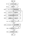
本実施例のGC装置における装置起動時の特徴的な制御動作を図2、図3を参照して説明する。図3は装置起動時の制御フローチャート、図2は装置起動時のキャリアガスの平均線速度の時間変化を示す図である。なお、ここでいう「装置起動」の前の状態とは、装置自体の主電源はオンされており制御部10では後述する分析のための条件設定などの動作が可能である一方、分析部本体は動作が停止した状態である。
A characteristic control operation at the time of starting the apparatus in the GC apparatus of this embodiment will be described with reference to FIGS. FIG. 3 is a control flowchart at the time of starting the apparatus, and FIG. 2 is a diagram showing a change with time in the average linear velocity of the carrier gas at the time of starting the apparatus. Here, the state before “device activation” means that the main power supply of the device itself is on and the
まずユーザーは入力部11から種々の分析条件を設定する(ステップS1)。即ち、分析条件設定処理部101は所定の分析条件設定画面を表示部12の画面上に表示し、ユーザーは入力部11で適宜の選択操作や数値入力などを行うことで、各種の分析条件を設定する。ここでいう分析条件は、使用するカラム7の内径及び長さ、使用するキャリアガスの種類、カラム入口圧、カラム出口圧、カラムオーブン温度条件(恒温/昇温の選択及び温度プログラム)を含む。カラム7の内径はカラム7自体の内径からカラム7の内壁に塗布された液相の膜厚を差し引いた実際の内径であることが望ましい。分析条件設定処理部101は入力された分析条件を分析条件記憶部102に保存する。
なお、すでに分析条件記憶部102に保存されている分析条件を利用する場合には、その旨を指示するのみでよい。
First, the user sets various analysis conditions from the input unit 11 (step S1). That is, the analysis condition setting
When using analysis conditions already stored in the analysis
また、カラム出口圧は使用される検出器8の種類に依存し、検出器の構造上、例えばカラム出口圧が大気圧になるものもあれば、検出器の検出セルに供給されるガス(例えばメイクアップガスやプラズマガスなど)の供給圧で決まるものもある。したがって、分析条件としてカラム出口圧の代わりに検出器8の種類を設定するようにしておき、設定された検出器8の種類に応じて、カラム出口圧を自動的に大気圧に定めたり或いはカラム出口圧を検出器の検出セルへのガス供給圧などに定めたりしてもよい。また、検出器8が質量分析装置である場合、カラム7の出口端は真空雰囲気となるから、カラム出口圧は予め決められた真空雰囲気のガス圧に定められるか、或いは後述すように真空雰囲気中のガス圧を検知する圧力センサの実測値に定められるとよい。
Further, the column outlet pressure depends on the type of the
次いで、ユーザーが入力部11から装置起動を指示すると(ステップS2)、この指示を受けてスタートタイム計算部103は次のようにしてスタートタイムtsを計算する(ステップS3)。
一般に、GC装置においてカラムを流れるキャリアガスの平均線速度Uは次の(1)式で計算することができる。
U=0.234375×(K/μ)×[{(Pin+Patm)2−(Pout+Patm)2 }2/{(Pin+Patm)3−(Pout+Patm)3}] …(1)
ここで、U:平均線速度 [cm/s]、K:(D×100)2/L、D:カラムの内径[mm]、L:カラムの長さ[m]、μ:キャリアガスの粘性係数[10-6 Pa・s]、Pin:カラム入口圧[kPa]、Pout:カラム出口圧[kPa]、Patm:大気圧[kPa]、である。また、キャリアガスの粘性係数μはキャリアガスの種類と温度(カラムオーブン温度)とによって決まる。
Next, when the user instructs to start the apparatus from the input unit 11 (step S2), the start
In general, the average linear velocity U of the carrier gas flowing through the column in the GC apparatus can be calculated by the following equation (1).
U = 0.234375 × (K / μ) × [{(Pin + Patm) 2 − (Pout + Patm) 2 } 2 / {(Pin + Patm) 3 − (Pout + Patm) 3 }] (1)
Here, U: average linear velocity [cm / s], K: (D × 100) 2 / L, D: column inner diameter [mm], L: column length [m], μ: carrier gas viscosity Coefficient [10 −6 Pa · s], Pin: Column inlet pressure [kPa], Pout: Column outlet pressure [kPa], Patm: Atmospheric pressure [kPa]. The viscosity coefficient μ of the carrier gas is determined by the type and temperature (column oven temperature) of the carrier gas.
上述したように分析条件情報記憶部102には分析条件として、カラム7の内径D及び長さL、カラム入口圧Pin、カラム出口圧Pout、キャリアガスの種類が記憶されている。また、大気圧Patmは通常、標準大気圧101.325[kPa]を用いればよいが、付設した大気圧センサにより検知した大気圧の実測値を用いてもよい。カラムオーブン温度は、ヒータ6に通電せず温調を行わない場合、一般的には、少なくともキャリアガスでカラム7を満たす程度の時間(数分から長くても十数分)の範囲内では、標準的な室温(例えば20〜25℃程度)又はヒータ6に付設されている温度センサ(図示せず)の初期的な検知温度で一定であるとみなすことができる。そこで、スタートタイム計算部103は分析条件情報記憶部102から必要な情報を読み出すとともに、必要に応じて温度センサ等の付設のセンサから必要な情報を収集し、それらを(1)式に適用して平均線速度Uを算出する。この場合には、カラムオーブン温度を始めとする分析条件が変化しないことを前提としているから、図2に示すように平均線速度も一定である。
As described above, the analysis condition
スタートタイム計算部103は上記平均線速度Uとカラムの長さLからカラム7中に存在する全ての残留ガスをキャリアガスで置換するのに要するガス置換所要時間t1を算出する。このガス置換所要時間t1をそのままスタートタイムtsにしてもよいが、計算の誤差や分析条件のパラメータ値のばらつき等を考慮して、適宜のマージンを見込むことが好ましい。例えば5%のマージンを見込んで1.05×taをスタートタイムtsとするとよい。
The start
上記スタートタイムtsの計算と並行して、分析制御部104はガス入口圧が設定された目標値になるように流量制御部13を介してフローコントローラ3におけるキャリアガス流量を制御し、一定の流量で以てキャリアガスの送給を開始する(ステップS4)。そして、分析制御部104はキャリアガスの送給開始とともに内部タイマによる計時を開始する(ステップS5)。そのあと、内部タイマの計時がスタートタイムtsに達したか否かを繰り返し判定する(ステップS6)。
In parallel with the calculation of the start time ts, the
試料気化室1を介してカラム7に送られるキャリアガスにより該カラム7中に残留していたガスは押し出されていき、カラム7中のガスは徐々にキャリアガスに置換される。図2にも示したようにキャリアガスの平均線速度は一定に維持されるから、残留ガスがキャリアガスに置換される速度も一定である。そして、内部タイマの計時がスタートタイムtsに達すると、分析制御部104は温度制御部14を介してヒータ6に加熱電流を供給し、設定された恒温又は昇温の条件に従ってカラムオーブン5の温度制御を開始する(ステップS7)。
The gas remaining in the
内部タイマの計時がスタートタイムtsに達した時点では、カラム7中のガスはキャリアガスに完全に置換されている。そのため、仮にステップS7においてカラムオーブン5の温度が急激に上昇されたとしても、カラム7中に残る酸素によるカラム7の液相の劣化を防止することができる。そして、カラムオーブン5の温度が例えば所定の初期温度に到達すると、分析制御部104は分析のための準備が完了したと判定し(ステップS8でYes)、実際の分析開始指示を受け付ける待機状態に移行する(ステップS9)。或いは、自動的なGC分析開始が指定されている場合には直ちにGC分析を開始する。
以上のようにして本実施例のGC装置では、カラム7内の残留ガスがキャリアガスに置換されたあとに遅滞なく、カラムオーブン5の温度を分析の初期温度まで上げることができる。
When the internal timer reaches the start time ts, the gas in the
As described above, in the GC apparatus of this embodiment, the temperature of the
なお、上記実施例では、カラム7内の残留ガスがキャリアガスで置換されるまでヒータ6への通電は行われないが、カラム7内に残る大気(酸素)による液相の酸化が生じないような低い温度であれば、この期間にカラムオーブン5の温調を実行してもよい。例えば、装置起動と同時にカラムオーブン5を50℃の温度一定に温調し、カラムオーブン温度が50℃であるとしてスタートタイムtsを計算してもよい。このようにカラムオーブン5を温調することによりキャリアガスの実際の平均線速度はほぼ一定になるため、計算により算出されたスタートタイムと実際に必要なスタートタイムとの誤差が小さくなる。
In the above embodiment, the
また、上記実施例の説明は装置起動時の制御であるが、上述した「INJ保守」機能のように、検出器8の温調が行われる等、カラム7へのキャリアガスの送給と試料気化室1及びカラムオーブン5の温調とが停止されている状態以外、他の構成要素は動作している状態から分析が可能な状態に装置が復帰する際の制御にも利用することができる。
Further, although the description of the above embodiment is the control at the time of starting the apparatus, the carrier gas is supplied to the
また上記実施例では、平均線速度を算出するためのカラム入口圧及び出口圧としては分析条件の一つとして設定された値が基本的に用いられていたが、付設された圧力センサにより実測された圧力値が計算に利用されるようにしてもよい。
また、カラム7の出口端には検出器8が直接接続されず、バックフラッシュ素子を介して検出器8が接続される場合があるが、この場合には、カラム出口圧はバックフラッシュ素子に接続するフローコントローラの制御圧とすればよい。また、図1に示した構成では、試料気化室1、カラム7、及び検出器8を含む分析ラインは一つのみであるが、分析ラインが複数並設されている構成のGC装置もある。その場合におけるスタートタイムtsの定め方については後述する。
In the above embodiment, the column inlet pressure and the outlet pressure for calculating the average linear velocity are basically the values set as one of the analysis conditions, but are actually measured by the attached pressure sensor. The pressure value may be used for the calculation.
In addition, the
また上記実施例では、スタートタイムtsに基づいてカラムオーブン5の温度制御が開始されるタイミングが自動的に決まるが、場合によっては、より長い時間、キャリアガスをカラム7に流し続けたあとにカラムオーブン5の温度制御が開始したいこともある。例えば、キャリアガスを流すことによりカラム7内部に付着した汚れを除去したいような場合である。そこで、上記実施例のGC装置では、予めユーザーが入力したスタートタイムと上述したように自動的に算出されるスタートタイムのいずれを使用するのかを選択可能としておき、いずれか選択されたほうのスタートタイムを用いてカラムオーブン5の温度制御を開始するタイミングを決めるようにしてもよい。
In the above embodiment, the timing at which the temperature control of the
また、スタートタイムの選択を予め行うのではなく、例えばステップS3でスタートタイムtsが算出されたあとにその値を表示部12の画面上に表示し、これを確認したユーザーが実際に制御に使用するスタートタイムを新たに入力し直したり、或いは表示されたスタートタイムを適宜修正したりできるようにしてもよい。
また、カラムオーブン5の温度制御が開始される時点までの残り時間を表示部12の画面上に表示し、それがゼロになる以前にユーザーが所定の操作を行うことで、残り時間が適宜の時間(例えば1分、3分など)だけ延長されるようにしてもよい。
Further, instead of selecting the start time in advance, for example, after the start time ts is calculated in step S3, the value is displayed on the screen of the
Further, the remaining time until the temperature control of the
[第2実施例]
次に、本発明の第2実施例であるGC装置を添付図面を参照して説明する。図4は第2実施例のGC装置の概略構成図、図5は装置起動時の制御フローチャートである。図4において、すでに説明した図1と同様の構成要素には同じ符号を付している。また、図5においてステップS11、S12、S18、S19は、図3におけるステップS1、S2、S8、S9と全く同じ処理を実施するステップである。
[Second Embodiment]
Next, a GC apparatus according to a second embodiment of the present invention will be described with reference to the accompanying drawings. FIG. 4 is a schematic configuration diagram of the GC apparatus according to the second embodiment, and FIG. 5 is a control flowchart when the apparatus is activated. In FIG. 4, the same components as those in FIG. Further, in FIG. 5, steps S11, S12, S18, and S19 are steps for performing exactly the same processing as steps S1, S2, S8, and S9 in FIG.
図4に示すように、本実施例のGC装置では、第1実施例のGC装置が備えていたスタートタイム計算部103に代えて待機時カラム入口圧計算部105を備える。
本実施例のGC装置における装置起動時の特徴的な制御動作を図5を参照して説明する。ユーザーにより装置起動が指示されると、待機時カラム入口圧計算部105は、(1)式で求まるキャリアガスの平均線速度から算出されるスタートタイム(ガス置換所要時間又はそれにマージンを加えた時間)が予め設定された目標値taに収まるような平均線速度を実現するためのカラム入口圧(ここで求まるカラム入口圧はユーザーにより設定されたカラム入口圧とは異なるため、以下「待機時カラム入口圧」と称す)を算出する(ステップS13)。これは第1実施例のGC装置におけるスタートタイムtsの逆算であることは明らかである。
As shown in FIG. 4, the GC device of this embodiment includes a standby column inlet
A characteristic control operation at the time of starting the apparatus in the GC apparatus of this embodiment will be described with reference to FIG. When the apparatus is instructed to start the apparatus, the standby column inlet
待機時カラム入口圧が求まると分析制御部104は、実際のカラム入口圧がユーザーにより設定されたカラム入口圧ではなく待機時カラム入口圧になるように流量制御部13を介してフローコントローラ3におけるキャリアガス流量を制御し、一定の流量で以てキャリアガスの送給を開始する(ステップS14)。そして、内部タイマによる計時を開始し、内部タイマの計時がスタートタイムの目標値taに達したか否かを繰り返し判定する(ステップS16)。計時が目標値taに達したならば、分析制御部104は、実際のカラム入口圧がユーザーにより設定されたカラム入口圧になるように目標値を変更して流量制御部13を介してフローコントローラ3におけるキャリアガス流量を制御するとともに、温度制御部14を介してヒータ6に加熱電流を供給し、設定された恒温又は昇温の条件に従ってカラムオーブン5の温度制御を開始する(ステップS17)。
When the standby column inlet pressure is obtained, the
この第2実施例のGC装置では、キャリアガスの種類等、カラム入口圧以外の分析条件が変わってもスタートタイムが一定になる。このため、温調開始までの待ち時間が常に同じであるという点でユーザーには都合がよい。 In the GC apparatus of the second embodiment, the start time is constant even if the analysis conditions other than the column inlet pressure, such as the type of carrier gas, change. For this reason, it is convenient for the user in that the waiting time until the start of temperature control is always the same.
[第3実施例]
続いて本発明の第3実施例であるGC装置を添付図面を参照して説明する。図6は第3実施例のGC装置の概略構成図、図7は装置起動時のキャリアガス平均線速度の時間変化の一例を示す図、図8は装置起動時の制御フローチャートである。図6において、すでに説明した図1と同様の構成要素には同じ符号を付している。また、図8においてステップS21、S22、S23、S29、S30は、図3におけるステップS1、S2、S4、S8、S9と全く同じ処理を実施するステップである。
[Third embodiment]
Next, a GC apparatus according to a third embodiment of the present invention will be described with reference to the accompanying drawings. FIG. 6 is a schematic configuration diagram of the GC device according to the third embodiment, FIG. 7 is a diagram showing an example of the time change of the carrier gas average linear velocity when the device is started, and FIG. 8 is a control flowchart when the device is started. In FIG. 6, the same components as those in FIG. Further, in FIG. 8, steps S21, S22, S23, S29, and S30 are steps for performing exactly the same processing as steps S1, S2, S4, S8, and S9 in FIG.
第3実施例のGC装置では、カラム7内のガスをキャリアガスで置換するまでの間にカラムオーブン5で温調を行わないことを想定している(もちろん、カラムオーブン5で温調を行っても構わないが、温調を行うのであれば敢えて第3実施例のGC装置の構成を採る必要性は低い)。カラムオーブン5で温調を行わない場合、カラムオーブン5内の温度は当該GC装置が設置された環境温度(室温)の影響を受ける。そのため、環境温度が変動するとカラムオーブン5内の温度が変動することがある。カラム7内のガスを置換すべくキャリアガスを送給しているときにカラムオーブン5内の温度が変動するとキャリアガスの平均線速度が変化するため、キャリアガスの平均線速度が一定であるとしてスタートタイムtsを計算するとズレが生じるおそれがある。
In the GC apparatus of the third embodiment, it is assumed that the temperature is not adjusted in the
通常、10分程度の間に環境温度がそれほど大きく変動することは考えにくいため、実際には上記のスタートタイムtsのズレはそれほど大きなものではないが、無駄な待ち時間をできるだけなくしつつ確実にカラム7内のガスを置換したい場合には、この第3実施例の構成とするとよい。図6に示すように、第3実施例のGC装置では、第1実施例のGC装置におけるスタートタイム計算部103に代えて、平均線速度計算部106、置換済みカラム長計算部107、及び置換終了判定部108を備える。
Normally, it is unlikely that the environmental temperature will fluctuate so much in about 10 minutes, so in practice the deviation of the above start time ts is not so great, but it is ensured that the wasteful waiting time is eliminated as much as possible. In the case where it is desired to replace the gas in 7, the configuration of the third embodiment is preferable. As shown in FIG. 6, in the GC apparatus of the third embodiment, instead of the start
本実施例のGC装置における装置起動時の特徴的な制御動作を図7、図8を参照して説明する。
ユーザーにより装置起動の指示がなされると、分析制御部104はガス入口圧が設定された目標値になるように流量制御部13を介してフローコントローラ3におけるキャリアガス流量を制御し、一定の流量で以てキャリアガスの送給を開始する(ステップS23)。次いで、平均線速度計算部106はカラムオーブン5内の温度を検出するための温度センサ(図示せず)により最新の温度を検知し(ステップS24)、その温度と分析条件情報記憶部102に格納されているカラムオーブン温度以外の情報、即ち、カラム入口圧、出口圧、カラム7の内径及び長さ、キャリアガスの種類を用いて、(1)式に基づいて平均線速度Uの最新値を算出する(ステップS25)。カラムオーブン温度が異なると(1)式中の粘性計数μが異なるため、平均線速度Uは変化する。
A characteristic control operation at the time of starting the apparatus in the GC apparatus of this embodiment will be described with reference to FIGS.
When the user gives an instruction to start the apparatus, the
置換済みカラム長計算部107は算出された平均線速度Uの最新値とキャリアガス送供開始時点からの経過時間とから、カラム7の全長Lの中でそれまでにキャリアガスに置換されたカラム長Laを計算する(ステップS26)。置換終了判定部108は計算されたカラム長Laがカラム7の全長を超えているか否かを判定することによりカラム7内のガスの置換が終了したか否かを判定する(ステップS27)。そして、ガスの置換が未だ終了していないと判定された場合には、ステップS27からS24へと戻り、ステップS24〜S27の処理を繰り返す。
The replaced column
カラムオーブン5内の温度が時間経過に伴い変化すると例えば図7に示すようにキャリアガスの平均線速度も変化する。キャリアガスに置換されたカラム長Laは図7において斜線で囲まれる領域の面積に相当するから、ステップS26における計算は実質的にはこの面積値の計算である。ステップS27においてカラム7内のガスの置換が終了したと判定されると、分析制御部104は温度制御部14を介してヒータ6に加熱電流を供給し、設定された恒温又は昇温の条件に従ってカラムオーブン5の温度制御を開始する(ステップS28)。なお、上記実施例と同様にステップS27では、計算されたカラム長Laがカラム7の全長を超えていると判定した時点からさらに所定のマージンを見込んだ時間が経過したときに置換が終了したと判定してもよい。或いは、置換済みのカラム長Laと比較するカラム7の全長自体をマージンを見込んで長くしておいても結果は同じである。
When the temperature in the
この第3実施例のGC装置では、カラムオーブン5の実際の温度をモニタしながら、その温度に基づく計算によりカラム7の中で実際にキャリアガスに置換された部分の長さを求め、それが実際のカラム7の全長を超えた時点又はそれよりも少し遅れた時点でカラムオーブン5の温度上昇を許可するようにしている。したがって、装置起動時点や装置復帰動作開始時点ではスタートタイムは決められず、いつスタートタイムが終了するのか不明であるという点で若干の不便さはあるが、カラムオーブン5の温調を行わなくてもカラム7内のガスが確実にキャリアガスに置換されたあとに無駄な時間を殆ど待つことなくカラムオーブン5の温度を上昇させることができるという利点がある。
In the GC apparatus of the third embodiment, while monitoring the actual temperature of the
上記実施例のGC装置ではいずれも分析ラインつまり試料気化室1、カラム7、及び検出器8の組み合わせが一つであったが、装置の構成によっては分析ラインが複数並列に設けられている場合がある。
図9は、試料気化室1が共通であり、カラム7a〜7bと検出器8a〜8cの組み合わせが複数ある場合の構成の例である(非特許文献1参照)。この場合には、試料気化室1に供給されたキャリアガスは三つのカラム7a〜7cに分岐して流れるから、各カラム7a〜7cにそれぞれ流れるキャリアガスの平均線速度と各カラム7a〜7cの長さによってスタートタイムが異なる。そこで、第1実施例のGC装置において図9に示した装置構成である場合には、カラム7a〜7c毎にそれぞれスタートタイムを計算し、その中で最も長いスタートタイムを採用してカラムオーブン5の温度制御を開始するタイミングを決めればよい。
In the GC apparatus of the above embodiment, there is only one combination of the analysis line, that is, the
FIG. 9 shows an example of a configuration when the
また、カラム入口圧などが変化しても複数のカラムにおけるスタートタイムの大小関係は変わらない。そこで、第2実施例のGC装置において図9に示した装置構成である場合には、まず複数のカラム7a〜7cに対しそれぞれスタートタイムを仮に計算して、スタートタイムが最も長くなるカラムを見つけておき、そのカラムに対するスタートタイムが目標値taを下回るように待機時カラム入口圧を決定すればよい。また第3実施例のGC装置において図9に示した装置構成である場合にも、まず複数のカラム7a〜7cに対しそれぞれスタートタイムを仮に計算して、スタートタイムが最も長くなるカラムを見つけておき、そのカラムに対してのみ図8で説明した手順で以てガス置換の終了のタイミングを判定すればよい。
Further, even if the column inlet pressure changes, the magnitude relationship of the start times in the plurality of columns does not change. Therefore, when the GC apparatus of the second embodiment has the apparatus configuration shown in FIG. 9, first, the start time is temporarily calculated for each of the plurality of
また、図9に示した構成では複数のカラムに対し試料気化室が共通であるが、試料気化室がカラム毎に独立に設けられている場合でも、同時に使用する試料気化室、カラム、検出器の組み合わせが分かれば、その組み合わせ毎にスタートタイムを計算することができる。そこで、同時に使用する試料気化室、カラム、検出器の組み合わせを分析条件の一つとしてユーザーが指定し、複数の組み合わせが指定されたときに、上記と同様にして最も長くなるスタートタイムを見つけ、これに基づきカラムオーブン5の温度制御を開始するタイミングを決めればよい。
In the configuration shown in FIG. 9, the sample vaporization chamber is common to a plurality of columns. However, even when the sample vaporization chamber is provided independently for each column, the sample vaporization chamber, the column, and the detector to be used simultaneously. If the combinations are known, the start time can be calculated for each combination. Therefore, the user specifies the combination of sample vaporization chamber, column, and detector to be used simultaneously as one of the analysis conditions, and when multiple combinations are specified, find the longest start time in the same way as above, Based on this, the timing for starting the temperature control of the
図10は、例えば質量分析計である検出器80が共通であり、試料気化室1a〜1b(フローコントローラ3a〜3bも)とカラム7a〜7bの組み合わせが複数である場合の構成の例である(特許文献4参照)。この場合には、カラム7a〜7b毎にフローコントローラ3a〜3bが独立して設けられているから、二つのカラム7a〜7bが同時に使用される場合もあればいずれか一つのみが選択的に使用される場合もある。したがって、どのカラム7a〜7bが使用されるのかが分析条件の一つとして予め設定され、その設定に応じて、一つのカラム7a〜7bのみが使用される場合にはその使用されるカラム7a〜7bに対応したスタートタイムを計算すればよい。また、二つ(又はそれ以上の複数)のカラム7a〜7bが同時に使用される場合には、カラム7a〜7b毎のスタートタイムを計算し、その中で最も長いスタートタイムを採用してカラムオーブン5の温度制御を開始するタイミングを決めればよい。
FIG. 10 shows an example of a configuration in the case where the
また、上記実施例は本発明の一例であるから、本発明の趣旨の範囲で適宜修正や変更、追加を行っても本願特許請求の範囲に包含されることは明らかである。 Moreover, since the said Example is an example of this invention, even if it corrects, changes, and adds suitably in the range of the meaning of this invention, it is clear that it is included by the claim of this application.
1、1a、1b…試料気化室
2、2a、2b…キャリアガス流路
3、3a、3b…フローコントローラ
4…インジェクタ
5…カラムオーブン
6…ヒータ
7、7a、7b、7c…カラム
8、8a、8b、8c、80…検出器
10…制御部
101…分析条件設定処理部
102…分析条件情報記憶部
103…スタートタイム計算部
104…分析制御部
105…待機時カラム入口圧計算部
106…平均線速度計算部
107…置換済みカラム長計算部
108…置換終了判定部
11…入力部
12…表示部
13…流量制御部
14…温度制御部
DESCRIPTION OF
Claims (5)
a)少なくとも、カラム入口圧及び出口圧、カラムの長さ及び内径、キャリアガスの種類、並びにカラムオーブンの温度に関する情報を収集する情報収集部と、
b)装置起動動作、又は、少なくとも前記カラムオーブンによる温調が停止され若しくは該カラムオーブンが所定の温度に維持され前記流量調節部からカラムへのキャリアガスの供給が停止している状態から分析実行のための定常待機状態に復帰させる装置復帰動作に際し、装置起動動作又は装置復帰動作の開始時点又はそれよりも以前のいずれかの時点で、前記情報収集部により収集された情報に基づいて、カラムに送給されるキャリアガスにより該カラム内のガスが置換されるに要する時間を算出する時間算出部と、
c)装置起動動作又は装置復帰動作の際に、前記流量調節部から前記カラムへのキャリアガスの供給を開始した時点から、前記時間算出部で算出された時間又はそれに所定の余裕を見込んだ時間が経過するまで待って前記カラムオーブンの温度上昇を伴う温度制御を許可する分析制御部と、
を備えることを特徴とするガスクロマトグラフ装置。 A column, a column oven in which the column is built, a detector for detecting a component in the sample after passing through the column, a flow rate adjusting unit for adjusting the flow rate of the carrier gas supplied to the column, A sample introduction unit for introducing a sample into the column by being placed on a carrier gas flow adjusted at the flow rate adjustment unit provided at an inlet of the column,
a) an information collecting unit for collecting at least information on column inlet pressure and outlet pressure, column length and inner diameter, carrier gas type, and column oven temperature;
b) Analyzing from the apparatus start-up operation, or at least the temperature adjustment by the column oven is stopped, or the column oven is maintained at a predetermined temperature and the supply of the carrier gas from the flow rate controller to the column is stopped. In the device return operation for returning to the steady standby state for the device, the column is based on the information collected by the information collection unit at any time before or before the start of the device start-up operation or the device return operation. A time calculation unit for calculating the time required for the gas in the column to be replaced by the carrier gas fed to
c) The time calculated by the time calculation unit or the time when a predetermined margin is expected from the time when the supply of the carrier gas from the flow rate adjustment unit to the column is started during the device start-up operation or device return operation. An analysis control unit that waits until elapse of time and permits temperature control with a temperature increase of the column oven,
A gas chromatograph apparatus comprising:
少なくとも前記カラムが複数並列に設けられ、該複数のカラムが共に分析に使用される場合に、前記時間算出部はカラム内のガスが置換されるに要する時間をカラム毎に計算し、前記分析制御部はカラム毎の前記時間の中で最も長い時間に基づいて前記カラムオーブンの温度制御を許可するタイミングを決めることを特徴とするガスクロマトグラフ装置。 The gas chromatograph apparatus according to claim 1,
When at least a plurality of the columns are provided in parallel and the plurality of columns are used for analysis, the time calculation unit calculates the time required for replacing the gas in the column for each column, and the analysis control The unit determines a timing for permitting temperature control of the column oven based on the longest time among the times for each column.
キャリアガス供給開始時点からカラムオーブン温度制御開始時点までの待機時間をユーザーが入力設定する入力設定部をさらに備え、
前記分析制御部は、前記時間算出部により算出された時間若しくはそれに所定の余裕を見込んだ時間と前記入力設定部により設定された待機時間とのいずれかを選択し、その選択した時間に基づいて前記カラムオーブンの温度制御を許可するタイミングを決めることを特徴とするガスクロマトグラフ装置。 A gas chromatograph apparatus according to claim 1 or 2,
The apparatus further includes an input setting unit in which a user inputs and sets a waiting time from the carrier gas supply start time to the column oven temperature control start time,
The analysis control unit selects either the time calculated by the time calculation unit or a time allowing a predetermined margin and the standby time set by the input setting unit, and based on the selected time A gas chromatograph apparatus for determining a timing for permitting temperature control of the column oven.
a)少なくとも、カラムの出口圧、カラムの長さ及び内径、キャリアガスの種類、及びカラムオーブン温度に関する情報を収集する情報収集部と、
b)装置起動、又は、少なくとも前記カラムオーブンによる温調が停止され若しくは該カラムオーブンが所定の温度に維持され前記流量調節部からカラムへのキャリアガスの供給が停止している状態から分析実行のための定常待機状態に復帰させる装置復帰動作に際し、装置起動動作又は装置復帰動作の開始時点又はそれよりも以前のいずれかの時点で、前記情報収集部により収集された情報に基づいて、カラムに送給されるキャリアガスによりカラム内のガスが置換されるに要する時間が目標値に収まるようなキャリアガスの平均線速度を実現可能であるカラム入口圧を計算する入口圧算出部と、
c)装置起動又は装置復帰動作の際に、前記入口圧算出部で算出されたカラム入口圧の設定の下で前記流量調節部から前記カラムへのキャリアガスの供給を開始した時点から、前記目標値又はそれに所定の余裕を見込んだ時間が経過するまで待って前記カラムオーブンの温度上昇を伴う温度制御を許可する分析制御部と、
を備えることを特徴とするガスクロマトグラフ装置。 A column, a column oven in which the column is built, a detector for detecting a component in the sample after passing through the column, a flow rate adjusting unit for adjusting the flow rate of the carrier gas supplied to the column, A sample introduction unit for introducing a sample into the column by being placed on a carrier gas flow adjusted at the flow rate adjustment unit provided at an inlet of the column,
a) an information collecting unit for collecting at least information on the outlet pressure of the column, the length and inner diameter of the column, the type of carrier gas, and the column oven temperature;
b) The analysis is started from the state where the apparatus is started or at least the temperature control by the column oven is stopped or the column oven is maintained at a predetermined temperature and the supply of the carrier gas from the flow rate controller to the column is stopped. In response to the device return operation for returning to the steady standby state, the information is collected in the column based on the information collected by the information collecting unit at the start time of the device start-up operation or the device return operation or any time before that. An inlet pressure calculation unit for calculating a column inlet pressure capable of realizing an average linear velocity of the carrier gas so that a time required for replacing the gas in the column with the carrier gas to be fed falls within the target value;
c) At the time of starting the apparatus or returning the apparatus, the target gas from the time when the supply of the carrier gas to the column from the flow rate adjusting unit is started under the setting of the column inlet pressure calculated by the inlet pressure calculating unit. An analysis control unit that waits until a time when a value or a predetermined allowance elapses and permits temperature control with a temperature increase of the column oven;
A gas chromatograph apparatus comprising:
a)少なくとも、カラムの入口圧及び出口圧、カラムの長さ及び内径、並びにキャリアガスの種類に関する情報を収集する情報収集部と、
b)前記カラムオーブン内部の温度又はその周囲の温度を検知する温度検知部と、
c)装置起動、又は、少なくとも前記カラムオーブンによる温調が停止され前記流量調節部からカラムへのキャリアガスの供給が停止している状態から分析実行のための定常待機状態に復帰させる装置復帰動作の際に、前記流量調節部から前記カラムへのキャリアガスの供給を開始したあと、前記情報収集部により収集された情報及び前記温度検知部により時間経過に伴って繰り返し検知される温度に基づいて、カラムに送給されたキャリアガスによりすでにキャリアガスに置換されたカラムの長さを計算する置換済み情報算出部と、
d)前記置換済み情報算出部により算出されたカラムの長さに基づきカラム内のガスが十分に置換されたか否かを判定し、十分に置換されたと判定されたあとに前記カラムオーブンの温度上昇を伴う温度制御を許可する分析制御部と、
を備えることを特徴とするガスクロマトグラフ装置。 A column, a column oven in which the column is built, a detector for detecting a component in the sample after passing through the column, a flow rate adjusting unit for adjusting the flow rate of the carrier gas supplied to the column, A sample introduction unit configured to introduce a sample into the column by being placed on a carrier gas flow adjusted at the flow rate adjustment unit provided at an inlet of the column,
a) an information collecting unit that collects information on at least the inlet and outlet pressures of the column, the length and inner diameter of the column, and the type of carrier gas;
b) a temperature detector for detecting the temperature inside the column oven or the surrounding temperature;
c) Device start-up or device return operation for returning from a state where temperature control by at least the column oven is stopped and supply of carrier gas from the flow rate control unit to the column is stopped to a steady standby state for analysis execution In this case, after starting the supply of the carrier gas from the flow rate adjusting unit to the column, based on the information collected by the information collecting unit and the temperature repeatedly detected over time by the temperature detecting unit A replaced information calculation unit that calculates the length of the column that has already been replaced by the carrier gas by the carrier gas supplied to the column;
d) Determine whether the gas in the column has been sufficiently replaced based on the length of the column calculated by the replaced information calculation unit, and after determining that the gas has been sufficiently replaced, increase the temperature of the column oven An analysis control unit that permits temperature control with
A gas chromatograph apparatus comprising:
Priority Applications (1)
| Application Number | Priority Date | Filing Date | Title |
|---|---|---|---|
| JP2016103166A JP6642271B2 (en) | 2016-05-24 | 2016-05-24 | Gas chromatograph |
Applications Claiming Priority (1)
| Application Number | Priority Date | Filing Date | Title |
|---|---|---|---|
| JP2016103166A JP6642271B2 (en) | 2016-05-24 | 2016-05-24 | Gas chromatograph |
Publications (2)
| Publication Number | Publication Date |
|---|---|
| JP2017211225A true JP2017211225A (en) | 2017-11-30 |
| JP6642271B2 JP6642271B2 (en) | 2020-02-05 |
Family
ID=60475433
Family Applications (1)
| Application Number | Title | Priority Date | Filing Date |
|---|---|---|---|
| JP2016103166A Active JP6642271B2 (en) | 2016-05-24 | 2016-05-24 | Gas chromatograph |
Country Status (1)
| Country | Link |
|---|---|
| JP (1) | JP6642271B2 (en) |
Cited By (5)
| Publication number | Priority date | Publication date | Assignee | Title |
|---|---|---|---|---|
| WO2020080404A1 (en) * | 2018-10-17 | 2020-04-23 | 株式会社島津製作所 | Temperature control analysis device and online analysis system having temperature control analysis device |
| WO2020157969A1 (en) * | 2019-02-01 | 2020-08-06 | 株式会社島津製作所 | Sulfur chemiluminescence detector |
| WO2021171548A1 (en) * | 2020-02-28 | 2021-09-02 | 株式会社島津製作所 | Gas chromatograph |
| WO2021171550A1 (en) * | 2020-02-28 | 2021-09-02 | 株式会社島津製作所 | Gas chromatograph |
| CN113588853A (en) * | 2020-04-30 | 2021-11-02 | 株式会社岛津制作所 | Analysis support device, analysis support method, and computer-readable storage medium |
Citations (9)
| Publication number | Priority date | Publication date | Assignee | Title |
|---|---|---|---|---|
| JPS623060U (en) * | 1985-06-24 | 1987-01-09 | ||
| JPH04138359A (en) * | 1990-09-28 | 1992-05-12 | Shimadzu Corp | Gas chromatograph |
| JPH0618502A (en) * | 1992-06-30 | 1994-01-25 | Shimadzu Corp | Gas chromatograph |
| JPH0943220A (en) * | 1995-07-26 | 1997-02-14 | Shimadzu Corp | Gas chromatograph device |
| JPH1019865A (en) * | 1996-07-02 | 1998-01-23 | Suzuki Motor Corp | Exhalation analyzer |
| JPH10325835A (en) * | 1997-04-15 | 1998-12-08 | Perkin Elmer Corp:The | Method for estimating hold time of gas chromatograph system |
| JP2011033419A (en) * | 2009-07-31 | 2011-02-17 | Shimadzu Corp | Control system for multi-dimensional gas chromatograph device, and the multi-dimensional gas chromatograph device using the system |
| JP2013044647A (en) * | 2011-08-24 | 2013-03-04 | Shimadzu Corp | Gas chromatography apparatus |
| JP2014002049A (en) * | 2012-06-19 | 2014-01-09 | Shimadzu Corp | Gas chromatograph |
-
2016
- 2016-05-24 JP JP2016103166A patent/JP6642271B2/en active Active
Patent Citations (10)
| Publication number | Priority date | Publication date | Assignee | Title |
|---|---|---|---|---|
| JPS623060U (en) * | 1985-06-24 | 1987-01-09 | ||
| JPH04138359A (en) * | 1990-09-28 | 1992-05-12 | Shimadzu Corp | Gas chromatograph |
| JPH0618502A (en) * | 1992-06-30 | 1994-01-25 | Shimadzu Corp | Gas chromatograph |
| JPH0943220A (en) * | 1995-07-26 | 1997-02-14 | Shimadzu Corp | Gas chromatograph device |
| JPH1019865A (en) * | 1996-07-02 | 1998-01-23 | Suzuki Motor Corp | Exhalation analyzer |
| JPH10325835A (en) * | 1997-04-15 | 1998-12-08 | Perkin Elmer Corp:The | Method for estimating hold time of gas chromatograph system |
| US5915269A (en) * | 1997-04-15 | 1999-06-22 | The Perkin-Elmer Corporation | Method and apparatus to compensate for gas chromatograph column permeability |
| JP2011033419A (en) * | 2009-07-31 | 2011-02-17 | Shimadzu Corp | Control system for multi-dimensional gas chromatograph device, and the multi-dimensional gas chromatograph device using the system |
| JP2013044647A (en) * | 2011-08-24 | 2013-03-04 | Shimadzu Corp | Gas chromatography apparatus |
| JP2014002049A (en) * | 2012-06-19 | 2014-01-09 | Shimadzu Corp | Gas chromatograph |
Cited By (12)
| Publication number | Priority date | Publication date | Assignee | Title |
|---|---|---|---|---|
| WO2020080404A1 (en) * | 2018-10-17 | 2020-04-23 | 株式会社島津製作所 | Temperature control analysis device and online analysis system having temperature control analysis device |
| WO2020157969A1 (en) * | 2019-02-01 | 2020-08-06 | 株式会社島津製作所 | Sulfur chemiluminescence detector |
| JPWO2020157969A1 (en) * | 2019-02-01 | 2021-10-28 | 株式会社島津製作所 | Chemiluminescent sulfur detector |
| JP7156406B2 (en) | 2019-02-01 | 2022-10-19 | 株式会社島津製作所 | Chemiluminescence sulfur detector |
| WO2021171548A1 (en) * | 2020-02-28 | 2021-09-02 | 株式会社島津製作所 | Gas chromatograph |
| JPWO2021171548A1 (en) * | 2020-02-28 | 2021-09-02 | ||
| WO2021171550A1 (en) * | 2020-02-28 | 2021-09-02 | 株式会社島津製作所 | Gas chromatograph |
| CN115053131A (en) * | 2020-02-28 | 2022-09-13 | 株式会社岛津制作所 | Gas chromatograph |
| CN115066608A (en) * | 2020-02-28 | 2022-09-16 | 株式会社岛津制作所 | Gas chromatograph |
| JP7226643B2 (en) | 2020-02-28 | 2023-02-21 | 株式会社島津製作所 | Gas chromatograph |
| CN115053131B (en) * | 2020-02-28 | 2023-09-12 | 株式会社岛津制作所 | Gas Chromatograph |
| CN113588853A (en) * | 2020-04-30 | 2021-11-02 | 株式会社岛津制作所 | Analysis support device, analysis support method, and computer-readable storage medium |
Also Published As
| Publication number | Publication date |
|---|---|
| JP6642271B2 (en) | 2020-02-05 |
Similar Documents
| Publication | Publication Date | Title |
|---|---|---|
| JP6642271B2 (en) | Gas chromatograph | |
| EP2317309B1 (en) | Gas chromatograph apparatus | |
| JP6314989B2 (en) | Gas chromatograph mass spectrometer | |
| JP6428793B2 (en) | Gas chromatograph | |
| US9435774B2 (en) | Gas chromatograph apparatus | |
| JP5682506B2 (en) | Gas chromatograph | |
| JP6264931B2 (en) | Liquid chromatograph and column oven used for it | |
| JP2005140659A (en) | Gradient liquid feed device | |
| JP2014185953A (en) | Gas chromatography device | |
| JP5275958B2 (en) | Liquid chromatograph | |
| JP6575384B2 (en) | Liquid chromatograph | |
| JP2015118011A (en) | Gas chromatograph | |
| JP2018136227A (en) | Gas chromatograph | |
| JP6686933B2 (en) | Chromatograph | |
| JP2018197669A (en) | Gas chromatography device | |
| JP7380324B2 (en) | Gas chromatograph | |
| CN113242969B (en) | Gas chromatograph, maintenance switching mode setting method, and computer-readable medium storing maintenance switching mode setting program | |
| JP6160526B2 (en) | Gas chromatograph apparatus and gas chromatograph analysis system | |
| JP4179189B2 (en) | Gas chromatograph | |
| WO2021171548A1 (en) | Gas chromatograph | |
| JP6669265B2 (en) | Gas chromatograph | |
| WO2020129137A1 (en) | Gas chromatograph, maintenance mode setting method, and maintenance mode setting program | |
| US20230221291A1 (en) | Element analysis method, element analysis device, and non-transitory computer readable medium storing program for element analysis device | |
| WO2019207850A1 (en) | Chromatographic analysis system |
Legal Events
| Date | Code | Title | Description |
|---|---|---|---|
| A621 | Written request for application examination |
Free format text: JAPANESE INTERMEDIATE CODE: A621 Effective date: 20180926 |
|
| A977 | Report on retrieval |
Free format text: JAPANESE INTERMEDIATE CODE: A971007 Effective date: 20190329 |
|
| A131 | Notification of reasons for refusal |
Free format text: JAPANESE INTERMEDIATE CODE: A131 Effective date: 20190507 |
|
| A521 | Request for written amendment filed |
Free format text: JAPANESE INTERMEDIATE CODE: A523 Effective date: 20190621 |
|
| TRDD | Decision of grant or rejection written | ||
| A01 | Written decision to grant a patent or to grant a registration (utility model) |
Free format text: JAPANESE INTERMEDIATE CODE: A01 Effective date: 20191203 |
|
| A61 | First payment of annual fees (during grant procedure) |
Free format text: JAPANESE INTERMEDIATE CODE: A61 Effective date: 20191216 |
|
| R151 | Written notification of patent or utility model registration |
Ref document number: 6642271 Country of ref document: JP Free format text: JAPANESE INTERMEDIATE CODE: R151 |