JP2017209530A - Light source device for endoscopes and endoscope system - Google Patents
Light source device for endoscopes and endoscope system Download PDFInfo
- Publication number
- JP2017209530A JP2017209530A JP2017163976A JP2017163976A JP2017209530A JP 2017209530 A JP2017209530 A JP 2017209530A JP 2017163976 A JP2017163976 A JP 2017163976A JP 2017163976 A JP2017163976 A JP 2017163976A JP 2017209530 A JP2017209530 A JP 2017209530A
- Authority
- JP
- Japan
- Prior art keywords
- light
- light source
- phosphor
- fluorescence
- emits
- Prior art date
- Legal status (The legal status is an assumption and is not a legal conclusion. Google has not performed a legal analysis and makes no representation as to the accuracy of the status listed.)
- Granted
Links
- OAICVXFJPJFONN-UHFFFAOYSA-N Phosphorus Chemical compound [P] OAICVXFJPJFONN-UHFFFAOYSA-N 0.000 claims abstract description 105
- 230000005284 excitation Effects 0.000 claims abstract description 93
- 230000003287 optical effect Effects 0.000 claims abstract description 90
- 238000003384 imaging method Methods 0.000 claims description 69
- 239000000463 material Substances 0.000 claims description 15
- 239000011230 binding agent Substances 0.000 claims description 7
- 238000005286 illumination Methods 0.000 description 36
- 239000010410 layer Substances 0.000 description 28
- 210000004204 blood vessel Anatomy 0.000 description 12
- 210000001519 tissue Anatomy 0.000 description 10
- 230000005540 biological transmission Effects 0.000 description 9
- 102000001554 Hemoglobins Human genes 0.000 description 7
- 108010054147 Hemoglobins Proteins 0.000 description 7
- 238000004891 communication Methods 0.000 description 6
- 238000003780 insertion Methods 0.000 description 6
- 230000037431 insertion Effects 0.000 description 6
- 230000015654 memory Effects 0.000 description 6
- 239000000126 substance Substances 0.000 description 6
- 238000002834 transmittance Methods 0.000 description 6
- XLYOFNOQVPJJNP-UHFFFAOYSA-N water Substances O XLYOFNOQVPJJNP-UHFFFAOYSA-N 0.000 description 5
- 238000005452 bending Methods 0.000 description 4
- 238000000926 separation method Methods 0.000 description 4
- 238000011282 treatment Methods 0.000 description 4
- 238000006243 chemical reaction Methods 0.000 description 3
- 238000010586 diagram Methods 0.000 description 3
- 210000001035 gastrointestinal tract Anatomy 0.000 description 3
- 238000011144 upstream manufacturing Methods 0.000 description 3
- 238000010521 absorption reaction Methods 0.000 description 2
- 230000000295 complement effect Effects 0.000 description 2
- 239000002131 composite material Substances 0.000 description 2
- 230000002596 correlated effect Effects 0.000 description 2
- 230000000875 corresponding effect Effects 0.000 description 2
- 238000001514 detection method Methods 0.000 description 2
- 230000001678 irradiating effect Effects 0.000 description 2
- 230000005499 meniscus Effects 0.000 description 2
- 230000004044 response Effects 0.000 description 2
- 238000005070 sampling Methods 0.000 description 2
- 239000004065 semiconductor Substances 0.000 description 2
- 229910052724 xenon Inorganic materials 0.000 description 2
- FHNFHKCVQCLJFQ-UHFFFAOYSA-N xenon atom Chemical compound [Xe] FHNFHKCVQCLJFQ-UHFFFAOYSA-N 0.000 description 2
- 238000012327 Endoscopic diagnosis Methods 0.000 description 1
- 206010028980 Neoplasm Diseases 0.000 description 1
- 230000002238 attenuated effect Effects 0.000 description 1
- 239000008280 blood Substances 0.000 description 1
- 210000004369 blood Anatomy 0.000 description 1
- 201000011510 cancer Diseases 0.000 description 1
- 238000003745 diagnosis Methods 0.000 description 1
- 210000003238 esophagus Anatomy 0.000 description 1
- 239000000835 fiber Substances 0.000 description 1
- 239000011521 glass Substances 0.000 description 1
- 229910052736 halogen Inorganic materials 0.000 description 1
- 150000002367 halogens Chemical class 0.000 description 1
- 210000000936 intestine Anatomy 0.000 description 1
- 230000003902 lesion Effects 0.000 description 1
- 229910044991 metal oxide Inorganic materials 0.000 description 1
- 150000004706 metal oxides Chemical class 0.000 description 1
- 210000004400 mucous membrane Anatomy 0.000 description 1
- 239000013307 optical fiber Substances 0.000 description 1
- 238000001228 spectrum Methods 0.000 description 1
- 239000002344 surface layer Substances 0.000 description 1
- 239000012780 transparent material Substances 0.000 description 1
- 230000003936 working memory Effects 0.000 description 1
Images


Abstract
Description
本発明は、励起光源と蛍光体とを有する内視鏡用光源装置及び内視鏡システムに関する。 The present invention relates to an endoscope light source device and an endoscope system having an excitation light source and a phosphor.
近年の医療においては、内視鏡用光源装置、電子内視鏡(以下、単に内視鏡という)、プロセッサ装置を備える内視鏡システムを用いた診断等が広く行われている。内視鏡用光源装置は、照明光を発生して検体内に照射する。内視鏡は、照明光が照射された検体内を、撮像素子により撮像して撮像信号を生成する。プロセッサ装置は、内視鏡により生成された撮像信号を画像処理して、モニタに表示するための観察画像を生成する。 In recent medical treatments, diagnosis using an endoscope system including an endoscope light source device, an electronic endoscope (hereinafter simply referred to as an endoscope), and a processor device is widely performed. The endoscope light source device generates illumination light and irradiates the sample. An endoscope images an inside of a specimen irradiated with illumination light with an image sensor and generates an imaging signal. The processor device performs image processing on the imaging signal generated by the endoscope, and generates an observation image to be displayed on the monitor.
従来、内視鏡用光源装置には、照明光として白色光を発するキセノンランプやハロゲンランプ等のランプ光源が使用されていたが、最近では、ランプ光源に代えて、特定の色の光を発するレーザダイオード(LD: Laser Diode)や発光ダイオード(LED: Light Emitting Diode)等の半導体光源が用いられつつある。 Conventionally, in an endoscope light source device, a lamp light source such as a xenon lamp or a halogen lamp that emits white light as illumination light has been used, but recently, a light of a specific color is emitted instead of the lamp light source. Semiconductor light sources such as laser diodes (LDs) and light emitting diodes (LEDs) are being used.
また、照明光の高輝度化を図るために、励起光(青色光)を発する励起光源(青色LD)と、励起光が照射されることにより蛍光(緑色光)を発する蛍光体とを設け、蛍光体により発せられた蛍光を内視鏡に供給する内視鏡用光源装置が知られている(特許文献1参照)。特許文献1には、蛍光体から励起光の入射方向とは反対方向に蛍光が射出される「反射型」と、蛍光体から励起光の入射方向に蛍光が射出される「透過型」とが記載されている。
In order to increase the brightness of illumination light, an excitation light source (blue LD) that emits excitation light (blue light) and a phosphor that emits fluorescence (green light) when irradiated with excitation light are provided. An endoscope light source device that supplies fluorescence emitted from a phosphor to an endoscope is known (see Patent Document 1).
反射型では、励起光を反射させて蛍光を透過させるダイクロイックミラーが、励起光の光路上に45°傾けて配置される。励起光源から発せられた励起光は、ダイクロイックミラーにより反射されて蛍光体に照射され、蛍光体からダイクロイックミラーに向けて発せられた蛍光が、ダイクロイックミラーを透過し、内視鏡に向けて射出される。 In the reflection type, a dichroic mirror that reflects excitation light and transmits fluorescence is disposed at an angle of 45 ° on the optical path of the excitation light. The excitation light emitted from the excitation light source is reflected by the dichroic mirror and applied to the phosphor, and the fluorescence emitted from the phosphor toward the dichroic mirror passes through the dichroic mirror and is emitted toward the endoscope. The
一方、透過型では、励起光を透過させて蛍光を反射させるダイクロイックミラーが、励起光源と蛍光体との間に配置される。励起光源から発せられた励起光は、ダイクロイックミラーを透過して蛍光体に照射され、蛍光体からダイクロイックミラーとは反対方向に発せられた蛍光が内視鏡に向けて射出される。ダイクロイックミラーは、蛍光体から励起光源側に向かった蛍光を反射して蛍光体に戻すことで、光射出効率を高めることを目的としている。 On the other hand, in the transmissive type, a dichroic mirror that transmits excitation light and reflects fluorescence is disposed between the excitation light source and the phosphor. Excitation light emitted from the excitation light source passes through the dichroic mirror and irradiates the phosphor, and fluorescence emitted from the phosphor in the direction opposite to the dichroic mirror is emitted toward the endoscope. The dichroic mirror is intended to increase the light emission efficiency by reflecting the fluorescence from the phosphor toward the excitation light source and returning it to the phosphor.
また、特許文献1に記載の内視鏡用光源装置では、蛍光(緑色光)の他に、青色光、赤色光、紫色光を発生するために、LEDにより構成された青色光源、赤色光源、紫色光源が設けられている。これらの光の光路を、蛍光体からの蛍光(緑色光)の光路と統合するために、各光源に対して1つずつダイクロイックミラーが設けられている。
In addition, in the endoscope light source device described in
これらの光のうち紫色光は、生体組織表層のヘモグロビンにより吸収されやすく、かつ血管周辺の生体組織内には殆ど拡散せずに反射される光である。緑色光は、紫色光よりも生体組織内に深く拡散し、かつヘモグロビンによる吸収も大きい光である。このため、生体組織表層の血管を強調するための血管強調観察モードでは、照明光として紫色光及び緑色光のみが用いられている。 Of these lights, violet light is light that is easily absorbed by hemoglobin on the surface layer of the living tissue and is reflected almost without diffusing into the living tissue around the blood vessel. Green light is light that diffuses deeper into the living tissue than violet light, and is more absorbed by hemoglobin. For this reason, in the blood vessel enhancement observation mode for emphasizing the blood vessels on the surface of the living tissue, only purple light and green light are used as illumination light.
しかし、照明光として紫色光及び緑色光のみを用いて得られる血管強調観察画像は、白色光を用いた通常観察画像より暗く、色再現性が低い疑似カラーの画像であることから、照明光として白色光を用い、この白色光から波長帯域が460nm〜500nmの波長帯域の光強度を低減させることにより血管コントラストの高い画像を得ることが知られている(特許文献2参照)。これは、460nm〜500nmの波長帯域の光が、ヘモグロビンには殆ど吸収されずに反射または散乱が生じやすいためである。 However, the blood vessel-enhanced observation image obtained using only purple light and green light as illumination light is a pseudo-color image that is darker than normal observation images using white light and has low color reproducibility. It is known that white light is used and an image with high blood vessel contrast is obtained by reducing the light intensity in the wavelength band of 460 nm to 500 nm from the white light (see Patent Document 2). This is because light in the wavelength band of 460 nm to 500 nm is hardly absorbed by hemoglobin and is likely to be reflected or scattered.
特許文献1に記載の反射型と透過型の内視鏡用光源装置のうち、透過型のほうが、装置構成を小型化することができるという利点がある。これは、反射型では、励起光の光路を折り曲げるために、ダイクロイックミラーを、励起光の光路に対して45°傾けて配置する必要があるが、透過型では、ダイクロイックミラーを傾ける必要がないためである。
Of the reflective and transmissive endoscope light source devices described in
この透過型の内視鏡用光源装置において、各光源を発光させて白色光を生成し、この白色光から、特許文献2に記載のように460nm〜500nmの波長帯域の光強度を低減させることにより、血管コントラストの高い画像を得ることが考えられる。
In this transmissive endoscope light source device, each light source emits light to generate white light, and from this white light, the light intensity in the wavelength band of 460 nm to 500 nm is reduced as described in
しかしながら、白色光から460nm〜500nmの波長帯域の光強度を低減させるには、460nm〜500nmの波長帯域の光に対する光透過率が低いノッチフィルタを設ける必要がある。単純にノッチフィルタを設けると、透過型を採用して装置構成を小型化したにも関わらず、装置構成が大型化するという問題がある。 However, in order to reduce the light intensity in the wavelength band of 460 nm to 500 nm from white light, it is necessary to provide a notch filter having a low light transmittance for light in the wavelength band of 460 nm to 500 nm. If the notch filter is simply provided, there is a problem in that the apparatus configuration is enlarged although the transmission structure is adopted to reduce the apparatus configuration.
本発明は、透過型の蛍光体を有する内視鏡用光源装置及び内視鏡システムにおいて、装置構成を大型化することなく、460nm以上500nm以下の波長帯域の光強度を低減することを可能とする内視鏡用光源装置及び内視鏡システムを提供することを目的とする。 The present invention makes it possible to reduce the light intensity in the wavelength band of 460 nm or more and 500 nm or less without enlarging the apparatus configuration in an endoscope light source device and endoscope system having a transmissive phosphor. It is an object to provide an endoscope light source device and an endoscope system.
上記目的を達成するために、本発明の内視鏡用光源装置は、励起光を発する励起光源と、励起光が照射されることにより蛍光を発する蛍光体であり、蛍光として、緑色光及び赤色光を発する蛍光体と、蛍光とは波長帯域が異なる特定光を発する第1光源と、蛍光の光路と特定光の光路とを統合する第2ダイクロイックミラーと、を備える。 In order to achieve the above object, an endoscope light source device of the present invention is an excitation light source that emits excitation light and a phosphor that emits fluorescence when irradiated with the excitation light. A phosphor that emits light, a first light source that emits specific light having a wavelength band different from that of fluorescence, and a second dichroic mirror that integrates the optical path of the fluorescence and the optical path of the specific light.
第2ダイクロイックミラーは、蛍光の光路と励起光の光路とを統合せずに、蛍光の光路と特定光の光路とを統合することが好ましい。特定光は、紫色光であることが好ましい。第2ダイクロイックミラーは、460nm以上500nm以下の波長帯域の光強度を低減させる特性を有することが好ましい。第2ダイクロイックミラーは、560nm以上590nm以下の波長帯域の光の光量を低減させる特性をさらに有することが好ましい。 The second dichroic mirror preferably integrates the optical path of the fluorescence and the optical path of the specific light without integrating the optical path of the fluorescence and the optical path of the excitation light. The specific light is preferably violet light. The second dichroic mirror preferably has a characteristic of reducing the light intensity in the wavelength band of 460 nm to 500 nm. The second dichroic mirror preferably further has a characteristic of reducing the amount of light in a wavelength band of 560 nm or more and 590 nm or less.
蛍光体は、緑色光を発する蛍光体材料と、赤色光を発する蛍光体材料とがバインダに分散された蛍光体層を有することが好ましい。蛍光体は固設されていることが好ましい。励起光源と蛍光体との間に配置され、励起光を透過させ、蛍光のうち励起光源側に向かう成分を反射させる第1ダイクロイックミラーを備えることが好ましい。 The phosphor preferably has a phosphor layer in which a phosphor material emitting green light and a phosphor material emitting red light are dispersed in a binder. The phosphor is preferably fixed. It is preferable to provide a first dichroic mirror that is disposed between the excitation light source and the phosphor, transmits the excitation light, and reflects a component of the fluorescence toward the excitation light source.
本発明の内視鏡システムは、励起光を発する励起光源と、励起光が照射されることにより蛍光を発する蛍光体であり、蛍光として、緑色光及び赤色光を発する蛍光体と、蛍光とは波長帯域が異なる特定光を発する第1光源と、蛍光の光路上に配置され、蛍光の光路と特定光の光路とを統合する第2ダイクロイックミラーと、を備える光源装置と、蛍光及び特定光が照射された観察部位からの反射光を撮像する撮像素子を有する内視鏡と、光源装置及び撮像素子の制御を行う制御部と、 を備える。 The endoscope system of the present invention is an excitation light source that emits excitation light, a phosphor that emits fluorescence when irradiated with the excitation light, a phosphor that emits green light and red light as fluorescence, and fluorescence. A light source device comprising: a first light source that emits specific light having a different wavelength band; and a second dichroic mirror that is arranged on the optical path of the fluorescence and integrates the optical path of the fluorescence and the optical path of the specific light; An endoscope having an image sensor that images reflected light from the irradiated observation site, and a control unit that controls the light source device and the image sensor.
本発明によれば、蛍光の光路と紫色光の光路とを統合する第2ダイクロイックミラーに、460nm以上500nm以下の波長帯域の光強度を低減させる特性を持たせているので、装置構成を大型化することなく、460nm以上500nm以下の波長帯域の光強度を低減することができる。 According to the present invention, the second dichroic mirror that integrates the optical path of fluorescence and the optical path of violet light has the characteristic of reducing the light intensity in the wavelength band of 460 nm or more and 500 nm or less. Without doing so, the light intensity in the wavelength band of 460 nm or more and 500 nm or less can be reduced.
[第1実施形態]
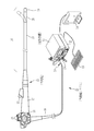
図1において、内視鏡システム10は、検体として生体内の観察部位を撮像する電子内視鏡(以下、単に内視鏡という)11と、撮像により得られた撮像信号に基づいて観察部位の表示画像を生成するプロセッサ装置12と、観察部位を照射する照明光を内視鏡11に供給する内視鏡用光源装置(以下、単に光源装置という)13と、表示画像を表示するモニタ14とを備えている。プロセッサ装置12には、キーボードやマウス等の操作入力部15が接続されている。
[First Embodiment]
In FIG. 1, an
内視鏡11は、生体の消化管内に挿入される挿入部16と、挿入部16の基端部分に設けられた操作部17と、内視鏡11をプロセッサ装置12及び光源装置13に接続するためのユニバーサルコード18とを備えている。挿入部16は、先端部19、湾曲部20、可撓管部21で構成されており、先端側からこの順番に連結されている。
The
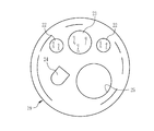
先端部19の先端面には、図2に示すように、観察部位に照明光を照射する照明窓22と、観察部位の像を取り込むための観察窓23と、観察窓23を洗浄するために送気・送水を行う送気・送水ノズル24と、鉗子や電気メス等の処置具を突出させて各種処置を行うための鉗子出口25とが設けられている。観察窓23の奥には、撮像素子33(図3参照)が内蔵されている。
As shown in FIG. 2, an
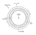
湾曲部20は、連結された複数の湾曲駒で構成されており、操作部17のアングルノブ26の操作に応じて、上下左右方向に湾曲する。湾曲部20を湾曲させることにより、先端部19が所望の方向に向けられる。可撓管部21は、可撓性を有しており、食道や腸等の曲がりくねった管道に挿入可能である。挿入部16には、撮像素子33を駆動するための駆動信号や、撮像素子33が出力する撮像信号を伝達する信号ケーブルや、光源装置13から供給される照明光を照明窓22に導光するライトガイド32(図3参照)が挿通されている。
The bending
操作部17には、アングルノブ26の他、処置具を挿入するための鉗子口27、送気・送水ノズル24から送気・送水を行う際に操作される送気・送水ボタン28、静止画像を撮影するためのフリーズボタン(図示せず)等が設けられている。
In addition to the
ユニバーサルコード18には、挿入部16から延設される通信ケーブルやライトガイド32が挿通されており、プロセッサ装置12及び光源装置13側の一端には、コネクタ29が取り付けられている。コネクタ29は、通信用コネクタ29aと光源用コネクタ29bからなる複合タイプのコネクタである。通信用コネクタ29aと光源用コネクタ29bとはそれぞれ、プロセッサ装置12と光源装置13とに着脱自在に接続される。通信用コネクタ29aには通信ケーブルの一端が配置されている。光源用コネクタ29bにはライトガイド32の入射端32a(図3参照)が配置されている。
A communication cable and a
図3において、光源装置13は、光源部30と、光源制御部31とを有している。光源部30は、光源制御部31の制御に基づき、照明光を出力する。光源部30から出力された照明光は、内視鏡11のライトガイド32の入射端32aに入射する。
In FIG. 3, the
内視鏡11は、ライトガイド32と、撮像素子33と、撮像駆動部34と、アナログ処理回路(AFE: Analog Front End)35と、照射レンズ36と、対物光学系37とを有している。ライトガイド32は、複数本の光ファイバをバンドル化したファイババンドルである。光源用コネクタ29bが光源装置13に接続されたときに、光源用コネクタ29bに配置されたライトガイド32の入射端32aが光源部30の出射端に対向する。先端部19に位置するライトガイド32の出射端は、2つの照明窓22にそれぞれ光が導光されるように、照明窓22の前段で2本に分岐している。
The
照明窓22の奥には、照射レンズ36が配置されている。光源装置13から供給された照明光は、ライトガイド32により照射レンズ36に導光されて照明窓22から観察部位に向けて照射される。照射レンズ36は、凹レンズであり、ライトガイド32から出射する照明光を、観察部位の広い範囲に照射する。
An
観察窓23の奥には、対物光学系37を介して撮像素子33が配置されている。観察部位の像(反射光)は、観察窓23を通して対物光学系37に入射し、対物光学系37によって撮像素子33の撮像面33aに結像される。
An imaging element 33 is disposed behind the
撮像素子33は、単板カラー方式のCCD(Charge Coupled Device)イメージセンサやCMOS(Complementary Metal Oxide Semiconductor)イメージセンサであり、光電変換により画素信号を生成する複数の画素が撮像面33aに形成されている。撮像面33aには、図4に示すカラーフィルタアレイ38が設けられている。このカラーフィルタアレイ38は、赤色(R)フィルタ38aと、緑色(G)フィルタ38bと、青色(B)フィルタ38cとで構成されている。各フィルタ38a,38b,38cは、1つの画素に対応して、その光入射側に配置されている。カラーフィルタアレイ38の色配列は、ベイヤー配列と呼ばれるものである。さらに、カラーフィルタアレイ38上には、各画素に対応してマイクロレンズ(図示せず)が設けられている。
The imaging device 33 is a single-plate color CCD (Charge Coupled Device) image sensor or a CMOS (Complementary Metal Oxide Semiconductor) image sensor, and a plurality of pixels that generate pixel signals by photoelectric conversion are formed on the imaging surface 33a. Yes. A
Rフィルタ38aが配置された画素は、後述する赤色光LRを受光する。Gフィルタ38bが配置された画素は、後述する緑色光LGを受光する。Bフィルタ38cが配置された画素は、後述する青色光LB及び紫色光LVを受光する。
The pixel in which the
撮像素子33は、撮像駆動部34により駆動され、撮像面33aに結像された像を、カラーフィルタアレイ38を介して複数の画素により撮像して撮像信号を出力する。撮像信号には、画素毎にR,G,Bのうちのいずれかの色信号(R信号、G信号、B信号)が含まれる。
The image pickup device 33 is driven by the image
AFE35は、相関二重サンプリング(CDS: Correlated Double Sampling)回路、自動ゲイン制御(AGC: Automatic Gain Control)回路、アナログ/デジタル(A/D)変換器等で構成されている。CDS回路は、撮像素子33から入力された撮像信号に対して相関二重サンプリング処理を施してノイズを除去する。AGC回路は、CDS回路によりノイズが除去された撮像信号を増幅する。A/D変換器は、AGC回路により増幅された撮像信号を、所定ビット数のデジタル信号に変換してプロセッサ装置12に入力する。
The
プロセッサ装置12は、制御部としてのコントローラ40と、DSP(Digital Signal Processor)41と、フレームメモリ42と、画像処理部43と、表示制御部44とを有している。コントローラ40は、CPU(Central Processing Unit)、制御プログラムや制御に必要な設定データを記憶するROM(Read Only Memory)や、制御プログラムをロードする作業メモリとしてのRAM(Random Access Memory)等を有し、CPUが制御プログラムを実行することにより、プロセッサ装置12の各部と、光源制御部31と、撮像駆動部34とを制御する。
The
DSP41は、通信用コネクタ29aを介してAFE35から入力される撮像信号に対して、画素補間処理、ガンマ補正、ホワイトバランス補正等の信号処理を施す。画素補間処理は、R信号、G信号、B信号の各信号について画素補間処理を行う。DSP41は、信号処理を施した撮像信号を、1フレーム周期毎に画像データとして、フレームメモリ42に記憶させる。
The
画像処理部43は、フレームメモリ42から画像データを読み出して、所定の画像処理を施して観察画像を生成する。表示制御部44は、画像処理部43により生成された画像を、コンポジット信号やコンポーネント信号等のビデオ信号に変換してモニタ14に出力する。
The
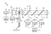
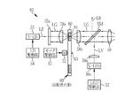
図5において、光源部30は、回転蛍光体50と、回転モータ51と、モータ駆動部52と、紫色レーザダイオード(V−LD)53と、LD駆動部54と、第1〜第4ダイクロイックミラー(DM)55a〜55dと、青色LED(B−LED)56aと、赤色LED(R−LED)56bと、紫色LED(V−LED)56cと、LED駆動部57と、第1〜第5コリメータレンズ58a〜58eと、集光レンズ59とを有する。
In FIG. 5, the
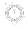
回転蛍光体50は、円盤状のホイール板60と、ホイール板60の一方の面に設けられた蛍光体層61とで構成されている。ホイール板60は、ガラス等の透明材料で形成されている。
The
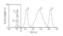
蛍光体層61は、図6に示すように、ホイール板60の一方の面に形成された凹部62に埋設されている。この凹部62は、ホイール板60の回転軸63を中心とした円周状に形成されている。蛍光体層61には、蛍光体材料として、例えばβ−SiAlON(β−Si6-xAlxOxN8-x)が分散されており、励起光源としてのV−LD53から射出される励起光LEを受けて緑色光LGを発する。緑色光LGは、図7に示すように、波長帯域が約480nm〜600nmであり、ピーク波長が約540nmである。
As shown in FIG. 6, the
LD駆動部54は、光源制御部31の制御に基づいて、V−LD53を駆動するためのLD駆動信号(駆動電流または駆動電圧)を生成し、V−LD53に供給する。V−LD53は、複数のLD素子(図示せず)を2次元アレイ状に配列したものである。V−LD53は、図7に示すように、励起光LEとして、ピーク波長が約405nmの紫色レーザ光を射出する。
The
第1DM55aは、V−LD53が射出する励起光LEの光路上で、かつ励起光LEの光路に対して垂直に配置されている。第1DM55aは、図8に示すように、約425nmに閾値λ1を有し、閾値λ1以上の波長の光を反射させ、閾値λ1より小さい波長の光を透過させる。すなわち、第1DM55aは、励起光LEを透過させる。回転蛍光体50は、蛍光体層61が、第1DM55aを透過した励起光LEの光路上に位置するように配置されている。
The
回転モータ51は、ホイール板60を、その回転軸63を中心として回転させる。モータ駆動部52は、光源制御部31の制御に基づいて回転駆動信号を生成し、回転モータ51に供給する。回転モータ51は、回転駆動信号に応じてホイール板60を回転させる。励起光LEは、ホイール板60が回転駆動されている状態で、蛍光体層61の一部分に連続的に照射される。したがって、蛍光体層61上の励起光LEの照射位置64は、ホイール板60の回転とともに移動し、照射位置64から緑色光LGが発生する。蛍光体層61で発生した緑色光LGは、散乱により前方及び後方に向かう。
The
第1コリメータレンズ58aは、凸面がV−LD53側に向けて配置された平凸レンズまたはメニスカスレンズであり、第1DM55aと回転蛍光体50との間に配置されている。第1コリメータレンズ58aは、蛍光体層61において後方(V−LD53側)に向かった緑色光LGを平行化して第1DM55aに向けて射出する。第1DM55aは、前述の光学特性により、緑色光LGを反射する。第1DM55aは、第1DM55aにより反射されて戻された緑色光LGを回転蛍光体50の蛍光体層61に集光する。
The
第2コリメータレンズ58bは、凸面がV−LD53とは反対側に向けて配置された平凸レンズまたはメニスカスレンズであり、回転蛍光体50のV−LD53とは反対側に配置されている。第2コリメータレンズ58bは、回転蛍光体50から入射する緑色光LGを平行化して、励起光LEの光路に沿って射出する。
The
B−LED56aは、図7に示すように、波長帯域が約430nm〜480nmで、ピーク波長が約460nmの青色光LBを発する。R−LED56bは、波長帯域が約580nm〜640nmで、ピーク波長が約620nmの赤色光LRを発する。V−LED56cは、波長帯域が約395nm〜415nmで、ピーク波長が約405nmの紫色光LVを発する。
As shown in FIG. 7, the B-
青色光LB及び紫色光LVは、生体組織表層のヘモグロビンでの吸収が大きく、かつ血管周辺の生体組織内には殆ど拡散せずに反射される光である。緑色光LGは、青色光LB及び紫色光LVよりも生体組織内に深く拡散し、かつヘモグロビンによる吸収も大きい光である。 The blue light LB and the violet light LV are light that is largely absorbed by hemoglobin on the surface of the living tissue and is reflected without being diffused into the living tissue around the blood vessel. The green light LG is light that diffuses deeper in the living tissue than the blue light LB and the purple light LV, and is also more absorbed by hemoglobin.
LED駆動部57は、光源制御部31の制御に基づいて、B−LED56a、R−LED56b、V−LED56cのそれぞれを駆動するためのLED駆動信号(駆動電流または駆動電圧)を生成し、各LED56a〜56cに供給する。
The
第3コリメータレンズ58cは、B−LED56aが射出する青色光LBの光路上に配置されており、この青色光LBを平行化して射出する。第2コリメータレンズ58bから射出される緑色光LGの光路と、第3コリメータレンズ58cから射出される青色光LBの光路とは直交しており、この交点に第2DM55bが配置されている。第2DM55bの一方の面に緑色光LGが45°の角度で入射し、他方の面に青色光LBが45°の角度で入射する。
The
第2DM55bは、図9に示すように、約490nmに閾値λ2を有し、閾値λ2以上の波長の光を透過させ、閾値λ2より小さい波長の光を反射させる。すなわち、第2DM55bは、第2コリメータレンズ58bから入射する緑色光LGを透過させ、第3コリメータレンズ58cから入射する青色光LBを反射させて光路を90°曲げる。これにより、緑色光LGの光路と青色光LBの光路とが統合される。また、第2DM55bは、第2コリメータレンズ58bから入射する励起光LEを反射させて、励起光LEを緑色光LG及び青色光LBの光路から除外する。これは、励起光LEは強度の高いレーザ光であるので、照明光にレーザ光が含まれると、照明光が照射された生体組織が破損される恐れがあるためである。
As shown in FIG. 9, the
第4コリメータレンズ58dは、R−LED56bが射出する赤色光LRの光路上に配置されており、この赤色光LRを平行化して射出する。第2DM55bから射出される緑色光LG及び青色光LBの光路と、第4コリメータレンズ58dから射出される赤色光LRの光路とは直交しており、この交点に第3DM55cが配置されている。
The
第3DM55cは、図10に示すように、約590nmに閾値λ3を有し、閾値λ3以上の波長の光を反射させ、閾値λ3より小さい波長の光を透過させる。すなわち、第3DM55cは、第2DM55bから入射する緑色光LG及び青色光LBを透過させ、第4コリメータレンズ58dから入射する赤色光LRを反射させて光路を90°曲げる。これにより、緑色光LG及び青色光LBの光路と、赤色光LRの光路とが統合される。
As shown in FIG. 10, the
第5コリメータレンズ58eは、V−LED56cが射出する紫色光LVの光路上に配置されており、この紫色光LVを平行化して射出する。第3DM55cから射出される緑色光LG、青色光LB、及び赤色光LRの光路と、第5コリメータレンズ58eから射出される紫色光LVの光路とは直交しており、この交点に第4DM55dが配置されている。
The
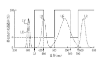
第4DM55dは、図11に示すように、約425nmに閾値λ4を有し、閾値λ4以上の波長の光を透過させ、閾値λ4より小さい波長の光を反射させる。また、第4DM55dは、460nm〜500nm(460nm以上500nm以下)の波長帯域の光強度を低減させるノッチ特性を有する。具体的には、第4DM55dの閾値λ4より大きい波長帯域の特性は、460nm〜500nmの波長帯域に対する光透過率がα(例えば、α=30%)であり、それ以外の光透過率はほぼ100%である。
As shown in FIG. 11, the
すなわち、第4DM55dは、第3DM55cから入射する緑色光LG、青色光LB、及び赤色光LRを透過させるとともに、460nm〜500nmの波長帯域の光強度を低減させ、第5コリメータレンズ58eから入射する紫色光LVを反射させて光路を90°曲げる。これにより、緑色光LG、青色光LB、及び赤色光LRの光路と、紫色光LVの光路とが統合される。
That is, the
集光レンズ59は、第4DM55dから射出される緑色光LG、青色光LB、赤色光LR、及び紫色光LVの光路上に配置されており、これらの光を集光する。また、集光レンズ59は、光源用コネクタ29bの近傍に配置されており、集光した光をライトガイド32の入射端32aに入射させる。
The condensing
次に、内視鏡システム10の作用を説明する。内視鏡診断を行う場合には、内視鏡11をプロセッサ装置12及び光源装置13に接続し、プロセッサ装置12及び光源装置13の電源を投入する。そして、内視鏡11の挿入部16を被検者の消化管内に挿入して、消化管内の観察を開始する。観察の開始指示は、操作入力部15により行われる。
Next, the operation of the
観察が開始すると、回転蛍光体50のホイール板60が回転されるとともに、V−LD53が駆動されて励起光LEが射出される。この励起光LEは、第1DM55aを透過し、第1コリメータレンズ58aを通過して回転蛍光体50の蛍光体層61に照射される。蛍光体層61は、励起光LEの照射に伴って緑色光LGを発する。
When the observation is started, the
この緑色光LGのうち、V−LD53側に向かう成分は、第1コリメータレンズ58aにより平行化されて第1DM55aに向かい、第1DM55aにより反射されて、再び第1コリメータレンズ58aに入射する。この緑色光LGは、第1コリメータレンズ58aにより集光されて、蛍光体層61に戻り、第2コリメータレンズ58bに向けて射出される。一方、蛍光体層61で発生した緑色光LGのうち、V−LD53とは反対側に向かう成分は、そのまま第2コリメータレンズ58bに入射する。
Of the green light LG, the component toward the V-
第2コリメータレンズ58bに入射した緑色光LGは、平行化して射出され、第2〜第4DM55b〜55dを透過して集光レンズ59に入射する。この緑色光LGは、第4DM55dを透過する際に、第4DM55dのノッチ特性により、460nm〜500nmの波長帯域の光強度が低減される。また、励起光LEは、蛍光体層61で緑色光LGの生成に寄与しなかった成分が、第2コリメータレンズ58bを通過するが、この励起光LEの成分は、第2DM55bにより反射されて、緑色光LGの光路から除外され、集光レンズ59には入射しない。
The green light LG that has entered the
また、緑色光LGの発生中に、B−LED56a、R−LED56b、V−LED56cが駆動され、青色光LB、赤色光LR、紫色光LVが射出される。青色光LBは、第3コリメータレンズ58cにより平行化された後、第2DM55bにより反射されて、緑色光LGに合波され、第3及び第4DM55c,55dを透過して集光レンズ59に入射する。この青色光LBは、第4DM55dを透過する際に、第4DM55dのノッチ特性により、460nm〜500nmの波長帯域の光強度が低減される。すなわち、第2DM55bは、緑色光LGの光路と励起光LEの光路とを統合せずに、緑色光LGの光路と青色光LBの光路とを統合する。
Further, during the generation of the green light LG, the B-
赤色光LRは、第4コリメータレンズ58dにより平行化された後、第3DM55cにより反射されて、緑色光LG及び青色光LBに合波され、第4DM55dを透過して集光レンズ59に入射する。紫色光LVは、第5コリメータレンズ58eにより平行化された後、第4DM55dにより反射されて、緑色光LG、青色光LB、及び赤色光LRに合波され、集光レンズ59に入射する。
The red light LR is collimated by the
集光レンズ59に入射した各光は、ライトガイド32の入射端32aに集光されて、ライトガイド32に照明光(白色光)として供給される。
Each light incident on the condensing
内視鏡11では、照明光がライトガイド32を介して照明窓22に導光され、照明窓22から観察部位に照射される。観察部位からの反射光は、観察窓23から対物光学系37を介して撮像素子33に入射する。撮像素子33は、1フレーム周期毎に入射光を撮像(光電変換)して撮像信号を生成する。撮像信号はそれぞれ、AFE35により、CDS、AGC、A/D変換等の処理が施され、デジタル信号としてプロセッサ装置12のDSP41に入力される。
In the
DSP41では、内視鏡11から入力された撮像信号に対して、画素補間処理、ガンマ補正、ホワイトバランス補正等の信号処理が施され、画像データとしてフレームメモリ42に記憶される。フレームメモリ42に記憶された画像データは、画像処理部43により所定の画像処理が施されて観察画像となり、表示制御部44を介してモニタ14に表示される。モニタ14に表示される観察画像は、1フレーム周期毎に更新される。
In the
この観察画像は、紫色光LV、青色光LB、緑色光LG、及び赤色光LRからなる白色の照明光から、血中ヘモグロビンには殆ど吸収されずに反射または散乱される460nm〜500nmの波長帯域の光強度を低減させた照明光を用いて検体を撮像した画像に相当するので、色再現性が高く、明るく、血管コントラストが高い画像である。 This observation image is a wavelength band of 460 nm to 500 nm that is reflected or scattered from white illumination light consisting of violet light LV, blue light LB, green light LG, and red light LR with almost no absorption by blood hemoglobin. Since this corresponds to an image obtained by imaging a specimen using illumination light with reduced light intensity, the image has high color reproducibility, is bright, and has high blood vessel contrast.
以上のように、460nm〜500nmの波長帯域の光強度を低減させるためのノッチ特性は、第4DM55dの光学特性に組み込まれているので、ノッチフィルタを設ける必要がなく、光源部30の装置構成を小型化することができる。
As described above, the notch characteristic for reducing the light intensity in the wavelength band of 460 nm to 500 nm is incorporated in the optical characteristic of the
なお、上記実施形態では、460nm〜500nmの波長帯域の光強度を低減させるためのノッチ特性を、図11に示すように、第4DM55dの光学特性に組み込んでいるが、図12に示すように、第3DM55cの光学特性に組み込むことも可能である。但し、第2DM55bは、460nm〜500nmの波長帯域に閾値λ2を有するので、第2DM55bの光学特性には、460nm〜500nmの波長帯域の光強度を低減させるためのノッチ特性を組み込むことはできない。
In the above embodiment, the notch characteristic for reducing the light intensity in the wavelength band of 460 nm to 500 nm is incorporated in the optical characteristic of the fourth DM55d as shown in FIG. 11, but as shown in FIG. It is also possible to incorporate the optical characteristics of the
上記実施形態では、第2〜第4DM55b〜55dを、上流側(V−LD53側)からこの順に配置しているが、第2DM55b、第4DM55d、第3DM55cの順に配置し、この配置に合わせてB−LED56a、R−LED56b、V−LED56c、及び第3〜第5コリメータレンズ58c〜58eを配置しても良い。第2DM55bは、青色光LBを合波するためのものであるので、前述のノッチ特性を有する第4DM55dまたは第3DM55cより上流側(回転蛍光体50側)に設ける必要がある。
In the above embodiment, the second to
上記実施形態では、第2DM55bを、閾値λ2以上の波長の光を透過させ、閾値λ2より小さい波長の光を反射させているが、これとは逆に、閾値λ2以上の波長の光を反射させ、閾値λ2より小さい波長の光を透過させるものとしても良い。この場合には、紫色光LVは、第2DM55bにより反射されることにより90°曲がり、この光路に、第2DM55bを透過する青色光LBの光路が統合される。励起光LEは、第2DM55bを透過することにより、紫色光LVの光路から除外され、集光レンズ59には入射しない。
In the above embodiment, the
同様に、第3DM55cを、閾値λ3以上の波長の光を透過させ、閾値λ3より小さい波長の光を反射させるものとしても良い。第4DM55dを、閾値λ4以上の波長の光を反射させ、閾値λ4より小さい波長の光を透過させるものとしても良い。この場合には、前述のノッチ特性を第4DM55dに持たせるために、図13に示すように、閾値λ4より大きい波長帯域において、460nm〜500nmの波長帯域に対する光透過率をβ(例えば、β=70%)とし、それ以外の光透過率をほぼ0%とすれば良い。
Similarly, the
したがって、第2〜第4DM55b〜55dは、それぞれ閾値以上の波長の光に対して反射及び透過のうちの一方を生じさせ、閾値より小さい波長の光に対して反射及び透過のうちの他方を生じさせれば良いので、第2〜第4DM55b〜55dの光学特性(反射又は透過)の組み合わせは、上記実施形態を含めて8通りのパターンが可能である。
Accordingly, each of the second to
また、第4DM55dに、460nm〜500nmの波長帯域の光強度を低減させるノッチ特性を設ける場合には、図14に示すように、このノッチ特性(第1のノッチ特性)に加えて、560nm〜590nm(560nm以上590nm以下)の波長帯域の光強度を低減させる第2のノッチ特性を持たせることが可能である。この第2のノッチ特性により、緑色光LG及び赤色光LRがそれぞれ部分的に減光され、緑色光LG及び赤色光LRの波長帯域が、従来のキセノン光源と波長選択フィルタとにより得られる波長帯域に近づき、従来の機器との親和性の点で好ましい。第2のノッチ特性の減光率は、第1のノッチ特性の減光率(光透過率α)と異なっていても良い。また、第2のノッチ特性の波長帯域は、560nm〜590nmに限られず、より広く、550nm〜600nmとしても良い。
Further, in the case where the
また、上記実施形態では、蛍光体層61を、緑色光LGのみを発するものとしているが、緑色光LGに加えて、その他の波長帯域光を発するよう構成しても良い。以下に、複数種の光を発する蛍光体層を有する回転蛍光体を備えた内視鏡システムの実施形態を示す。
[第2実施形態]
第2実施形態では、第1実施形態の回転蛍光体50に代えて、図15に示す回転蛍光体70を用いる。回転蛍光体70は、ホイール板60の凹部62に、緑色光LG(第1蛍光)を発する第1領域71aと、青色光LB(第2蛍光)を発する第2領域71bとを有する蛍光体層71が設けられている。第1領域71aは、バインダ(図示せず)に、蛍光体材料として、例えばβ−SiAlON(β−Si6-xAlxOxN8-x)を分散させた領域であり、励起光LEを受けて緑色光LGを発する。第2領域71bは、バインダ(図示せず)に、蛍光体材料として、例えばBAM(BaMgAl10O17:Eu2+)を分散させた領域であり、励起光LEを受けて青色光LBを発する。
Moreover, in the said embodiment, although the
[Second Embodiment]
In the second embodiment, a
本実施形態の光源部72は、図16に示すように、図5に示す光源部30の構成から、B−LED56a、第3コリメータレンズ58c、及び第2DM55bを削除したものである。その他の構成は、第1実施形態と同様である。
As illustrated in FIG. 16, the
本実施形態では、ホイール板60の回転に伴って、第1領域71a及び第2領域71bが励起光LEの照射位置64(図15参照)を通過し、緑色光LGと青色光LBとが交互に発せられる。回転蛍光体70から発せられた緑色光LG及び青色光LBのうち、V−LD53側に向かう成分は、第1DM55aにより反射されて、回転蛍光体70に戻され、第2コリメータレンズ58bに入射する。緑色光LG及び青色光LBのうち、V−LD53とは反対側に向かう成分は、そのまま第2コリメータレンズ58bに入射する。
In the present embodiment, with the rotation of the
第2コリメータレンズ58bから射出された緑色光LG及び青色光LBは、第3及び第4DM55c,55dを透過して集光レンズ59に入射する。緑色光LG及び青色光LBは、第4DM55dを透過する際に、第4DM55dのノッチ特性により、460nm〜500nmの波長帯域の光強度が低減される。なお、本実施形態では、第2DM55bが設けられていないので、励起光LEは、第3DM55cを透過して第4DM55dに入射し、第4DM55dにより反射されることで、緑色光LG及び青色光LBの光路から除外され、集光レンズ59には入射しない。
The green light LG and the blue light LB emitted from the
R−LED56b及びV−LED56cから射出される赤色光LR及び紫色光LVの各光路は、第3及び第4DM55c,55dにより、緑色光LG及び青色光LBの光路に統合される。すなわち、第4DM55dは、緑色光LG及び赤色光LRの光路と励起光LEの光路とを統合せずに、緑色光LG及び赤色光LRの光路と紫色光LVの光路とを統合する。
The optical paths of the red light LR and the purple light LV emitted from the R-
次に、光源部72及び撮像素子33の駆動タイミングについて説明する。コントローラ40により、光源制御部31と撮像駆動部34とが制御されることにより、回転蛍光体70の回転、R−LED56b及びV−LED56cの発光、撮像素子33の撮像は、互いに同期して制御される。
Next, drive timings of the
コントローラ40は、ホイール板60の回転位置を検出する回転位置検出センサ(図示せず)の検出値に基づいて、R−LED56b及びV−LED56cの発光タイミングと、撮像素子33の撮像タイミングとを制御する。
The
具体的には、コントローラ40は、回転蛍光体70のホイール板60を一定の周期Tで回転させ、V−LD53を駆動して励起光LEを射出させる。この励起光LEの発光強度は一定である。図17に示すように、回転周期Tの前半は、前述の第1領域71aが励起光LEの照射位置64を通過している期間(以下、第1期間P1という)であり、緑色光LGが発せられる。回転周期Tの後半は、第2領域71bが照射位置64を通過している期間(以下、第2期間P2という)であり、青色光LBが発せられる。
Specifically, the
コントローラ40は、第1期間P1にのみV−LED56cを駆動して紫色光LVを発生させ、第2期間P2にのみR−LED56bを駆動して赤色光LRを発生させる。これにより、第1期間P1には、緑色光LGと紫色光LVとが合波された光(以下、第1照明光という)が、光源部30から内視鏡11のライトガイド32に供給される。第2期間P2には、青色光LBと赤色光LRとが合波された光(以下、第2照明光という)が、光源部30から内視鏡11のライトガイド32に供給される。
The
コントローラ40は、撮像素子33に、第1期間P1と第2期間P2とのそれぞれにおいて撮像動作を行わせる。すなわち、撮像素子33は、第1期間P1では、第1照明光により照明された検体を撮像して撮像信号(以下、第1撮像信号S1という)を生成し、第2期間P2では、第2照明光により照明された検体を撮像して撮像信号(以下、第2撮像信号S2という)を生成する。
The
ここで、第1照明光に含まれる緑色光LGと紫色光LVとは、波長帯域が互いに離れているので、撮像素子33により色分離性良く撮像が行われる。同様に、第2照明光に含まれる青色光LBと赤色光LRとは、波長帯域が互いに離れているので、撮像素子33により色分離性良く撮像が行われる。 Here, since the wavelength bands of the green light LG and the violet light LV included in the first illumination light are separated from each other, the imaging element 33 performs imaging with good color separation. Similarly, the blue light LB and the red light LR included in the second illumination light are separated from each other in wavelength, so that the imaging element 33 captures an image with good color separation.
DSP41は、第1撮像信号S1に含まれるG信号及びB信号と、第2撮像信号S2に含まれるB信号及びR信号とに基づいて画像データを生成する。なお、第1撮像信号S1に含まれるB信号は、紫色光LVに基づくものであり、第2撮像信号S2に含まれるB信号は、青色光LBに基づくものである。画像データを生成する際には、第1撮像信号S1に含まれるB信号と第2撮像信号S2に含まれるB信号とを同一の画素毎に加算したものをB信号とする。そして、このB信号と、G信号及びR信号とを用いて前述の信号処理を行うことにより画像データが生成される。
The
DSP41は、図18に示すように、撮像素子33から第1撮像信号S1または第2撮像信号S2が得られるたびに、得られた撮像信号と、その直前に得られた撮像信号とを用いて1フレーム分の画像データを生成する。すなわち、回転周期Tの半分(T/2)が前述の1フレーム周期である。
As shown in FIG. 18, the
このように第1及び第2撮像信号S1,S2により得られる画像データに基づく観察画像は、フルカラーの画像である。なお、この観察画像に加えて、第1撮像信号S1のみから観察画像を生成しても良い。第1撮像信号S1は、緑色光LGと紫色光LVとに基づく信号であるので、第1撮像信号S1に基づく観察画像は、表層血管等が強調された擬似カラーの画像である。 Thus, the observation image based on the image data obtained from the first and second imaging signals S1 and S2 is a full-color image. In addition to this observation image, an observation image may be generated only from the first imaging signal S1. Since the first imaging signal S1 is a signal based on the green light LG and the purple light LV, the observation image based on the first imaging signal S1 is a pseudo color image in which the surface blood vessels and the like are emphasized.
第2実施形態では、緑色光LG及び青色光LBは、蛍光体により生成されたものであり、共に高輝度であるので、緑色光LGと青色光LBとの強度のバランスが保たれる。 In the second embodiment, the green light LG and the blue light LB are generated by a phosphor and both have high luminance, so that the intensity balance between the green light LG and the blue light LB is maintained.
第2実施形態においても、第4DM55dを、第3DM55cより上流側(V−LD53側)に配置することが可能であるが、第4DM55dを下流側に配置する場合には、第4DM55dに、460nm〜500nmの波長帯域の光強度を低減させる第1のノッチ特性に加えて、560nm〜590nmの波長帯域の光強度を低減させる第2のノッチ特性を持たせることが可能である。また、第3及び第4DM55c,55dの光学特性(反射又は透過)は変更可能であり、図16に示す構成を含めて4通りのパターンの変形が可能である。
Also in the second embodiment, the
第2実施形態では、図17に示すように、撮像素子33の撮像周期を回転周期Tの半分とし、第1期間P1と第2期間P2とでそれぞれ個別に撮像動作を行っているが、撮像素子33の撮像周期を回転周期Tと一致させ、1回転周期Tで1回の撮像動作を行っても良い。この場合には、第1照明光で照明された検体像と第2照明光で照明された検体像とが混合されて撮像されるため、第2実施形態に比べて撮像の色分離性は低下するが、DSP41による画像データを生成するための信号処理が簡便化される。
In the second embodiment, as shown in FIG. 17, the imaging cycle of the imaging device 33 is half of the rotation cycle T, and the imaging operation is performed individually in the first period P1 and the second period P2, respectively. The imaging cycle of the element 33 may coincide with the rotation cycle T, and one imaging operation may be performed at one rotation cycle T. In this case, since the sample image illuminated with the first illumination light and the sample image illuminated with the second illumination light are mixed and imaged, the color separation of imaging is reduced as compared with the second embodiment. However, the signal processing for generating image data by the
また、この場合には、R−LED56b及びV−LED56cを常時駆動して、赤色光LR及び紫色光LVを常時点灯させても良い。また、撮像素子33の撮像周期を回転周期Tの整数倍に一致させても良い。さらに、回転周期Tが撮像周期に対して十分に小さい場合には、撮像周期を回転周期Tの整数倍に一致させず、撮像素子33の撮像と回転蛍光体70の回転とを非同期としても良い。
In this case, the R-
第2実施形態では、V−LD53による励起光LEの発光強度を一定としているが、第1期間P1と第2期間P2とで励起光LEの発光強度を変更することも好ましい。励起光LEの発光強度に応じて、緑色光LGと青色光LBとの発光強度がそれぞれ変化するので、第1期間P1と第2期間P2とで励起光LEの発光強度を変更することにより、緑色光LGと青色光LBとの光量比を変更することができる。
In the second embodiment, the emission intensity of the excitation light LE by the V-
緑色光LGと青色光LBとの光量比は、遠景観察時と近景観察時とで変更することが好ましい。遠景観察とは、内視鏡11の先端部19を検体から離した位置で観察することであり、表層血管及び中深層血管の位置関係を含む被観察部位の全体の状態を観察することを主目的とするものである。これに対して、近景観察とは、内視鏡11の先端部19を検体に近接させた位置で観察することであり、早期癌などによる病変が現れやすい表層血管を集中的に観察することを主目的とするものである。
The light quantity ratio between the green light LG and the blue light LB is preferably changed between the distant view observation and the near view observation. The distant view observation is to observe the
遠景観察時には、近景観察時よりも観察画像の明るさが低下するので、青色光LBの光量に対する緑色光LGの光量比RG/Bを大きくすることが好ましい。これは、緑色光LGは、青色光LBに比べて、ヘモグロビンの吸収係数や生体組織内での散乱係数が低いため、生体組織内をより深くかつ広く拡散し、粘膜等を効率よく照明することによる。 At the time of distant view observation, since the brightness of the observation image is lower than that at the time of close view observation, it is preferable to increase the light amount ratio R G / B of the green light LG to the light amount of the blue light LB. This is because green light LG has a lower hemoglobin absorption coefficient and scattering coefficient in living tissue than blue light LB, so that it diffuses deeper and wider in living tissue and efficiently illuminates mucous membranes and the like. by.
この光量比RG/Bの変更は、例えば、操作入力部15からの入力信号に基づいて行えば良い。具体的には、操作入力部15により、遠景観察モードと近景観察モードとを設定可能とし、遠景観察モードが設定された場合には、近景観察モードの場合より光量比RG/Bを大きくする。これに代えて、撮像素子33により取得される撮像信号に基づいて露光量を求め、この露光量に基づいて光量比RG/Bを制御しても良い。具体的には、露光量が一定値以下の場合には遠景観察状態にあると判定し、露光量が一定値より大きい場合には近景観察状態にあると判定すれば良い。
[第3実施形態]
第3実施形態では、蛍光体層71中の第1領域71aに、励起光LEを受けて緑色光LG(第1蛍光)を発する蛍光体材料(β−SiAlON等)に加えて、励起光LEを受けて赤色光LR(第3蛍光)を発する蛍光体材料(例えば、CASN(CaAlSiN3:Eu2+))を含有させ、図16に示す光源部72の構成から、R−LED56b、第4コリメータレンズ58d、及び第3DM55cを削除する。
The change of the light quantity ratio R G / B may be performed based on an input signal from the
[Third Embodiment]
In the third embodiment, excitation light LE is added to the
第3実施形態では、第1領域71aから、緑色光LGと赤色光LRとが混合された黄色光が発せられる。その他の構成は、第2実施形態と同様である。
[第4実施形態]
第4実施形態では、図19に示すように、ホイール板60の凹部62に、第1〜第3領域81a〜81cを有する蛍光体層81が設けられた回転蛍光体80を用いる。第1及び第2領域81a,81bは、第2実施形態の第1及び第2領域71aと同様に、励起光LEを受けて緑色光LG(第1蛍光)及び青色光LB(第2蛍光)をそれぞれ発生する。
In the third embodiment, yellow light in which green light LG and red light LR are mixed is emitted from the
[Fourth Embodiment]
In the fourth embodiment, as shown in FIG. 19, a
第3領域81cは、励起光LEを受けて赤色光LR(第3蛍光)を発生する。第3領域81cは、バインダ(図示せず)に、蛍光体材料として、例えばCASN(CaAlSiN3:Eu2+)を分散させた領域である。
The
本実施形態の光源部82は、図20に示すように、図16に示す光源部72の構成から、R−LED56b、第4コリメータレンズ58d、及び第3DM55cを削除したものである。その他の構成は、第1実施形態と同様である。
As shown in FIG. 20, the light source unit 82 of the present embodiment is obtained by deleting the R-
本実施形態では、ホイール板60の回転に伴って、第1領域81a、第2領域81b、第3領域81cが励起光LEの照射位置64を順に通過し、緑色光LG、青色光LB、赤色光LRが順に発せられる。緑色光LG、青色光LB、赤色光LRは、第4DM55dを透過する際に、第4DM55dのノッチ特性により、460nm〜500nmの波長帯域の光強度が低減される。
In the present embodiment, as the
本実施形態では、撮像素子33として、カラーフィルタアレイを有していないモノクロのイメージセンサ(以下、モノクロセンサという)を用いることも可能である。撮像素子33としてモノクロセンサを用いる場合には、緑色光LG、青色光LB、赤色光LRの各発光期間に合わせて撮像を行えば良い。この場合には、青色光LBの発光期間(第2期間P2)に、V−LED56cを駆動して紫色光LVを発光させることが好ましい。
In the present embodiment, a monochrome image sensor (hereinafter referred to as a monochrome sensor) that does not have a color filter array can be used as the image sensor 33. When a monochrome sensor is used as the imaging element 33, imaging may be performed in accordance with each light emission period of the green light LG, the blue light LB, and the red light LR. In this case, it is preferable that the V-
一方、撮像素子33として単板カラー方式のイメージセンサ(以下、カラーセンサという)を用いる場合には、赤色光LRの発光期間(第3領域81cが励起光LEの照射位置64を通過している期間)に、V−LED56cを駆動して紫色光LVを発光させることが好ましい。赤色光LRと紫色光LVとは、波長帯域が互いに離れているので、撮像素子33により色分離性良く撮像が行われる。
[第5実施形態]
第5実施形態では、図21に示すように、ホイール板60の凹部62に、第1〜第3蛍光体材料91a〜91cと、これらが分散されたバインダ91dとで構成された蛍光体層91を有する回転蛍光体90を用いる。第1蛍光体材料91aは、励起光LEを受けて緑色光LG(第1蛍光)を発する。第2蛍光体材料91bは、励起光LEを受けて青色光LB(第2蛍光)を発する。第3蛍光体材料91cは、励起光LEを受けて赤色光LR(第3蛍光)を発する。
On the other hand, when a single-plate color image sensor (hereinafter referred to as a color sensor) is used as the image sensor 33, the emission period of the red light LR (the
[Fifth Embodiment]
In the fifth embodiment, as shown in FIG. 21, a
本実施形態の光源部は、第4実施形態と同様に、図16に示す光源部72の構成から、R−LED56b、第4コリメータレンズ58d、及び第3DM55cを削除したものである。その他の構成は、第1実施形態と同様である。
As in the fourth embodiment, the light source unit of the present embodiment is obtained by deleting the R-
本実施形態では、蛍光体層91への励起光LEの照射により、蛍光体層91から、緑色光LG、青色光LB、及び赤色光LRが混合された光(白色光)が発せられる。このため、撮像素子33としては、カラーセンサを用い、モノクロセンサを用いることはできない。本実施形態では、ホイール板60の回転中、V−LED56cを駆動して紫色光LVを常時発光させる。その他の構成は、第1実施形態と同様である。
In the present embodiment, the
第4及び第5実施形態においても、第4DM55dに、460nm〜500nmの波長帯域の光強度を低減させる第1のノッチ特性に加えて、560nm〜590nmの波長帯域の光強度を低減させる第2のノッチ特性を持たせることが可能である。また、第4DM55dの光学特性の反射と透過の関係を逆とすることも可能である。
Also in the fourth and fifth embodiments, in addition to the first notch characteristic for reducing the light intensity in the wavelength band of 460 nm to 500 nm, the
上記各実施形態では、青色光LBのピーク波長を約460nm、緑色光LGのピーク波長を約540nmとしているが、青色光LBのピーク波長は460nm以下であれば良く、緑色光LGのピーク波長は500nm以上であれば良い。 In each of the above embodiments, the peak wavelength of the blue light LB is about 460 nm and the peak wavelength of the green light LG is about 540 nm. However, the peak wavelength of the blue light LB may be 460 nm or less, and the peak wavelength of the green light LG is What is necessary is just 500 nm or more.
上記各実施形態では、カラーセンサに、原色型のカラーフィルタアレイ38を設けているが、これに代えて、補色型のカラーフィルタアレイを設けても良い。
In each of the embodiments described above, the color sensor is provided with the primary
上記各実施形態では、第1DM55aが回転蛍光体とは別体として設けられているが、ホイール板の蛍光体層の背面側(V−LD53側)に第1DM55aを設けても良い。
In each of the above embodiments, the
上記各実施形態では、蛍光体を、回転駆動される回転蛍光体としているが、蛍光体は、固設されて回転しないものであっても良い。 In each of the above embodiments, the phosphor is a rotating phosphor that is rotationally driven. However, the phosphor may be fixed and not rotated.
上記各実施形態では、光源装置とプロセッサ装置とを別体構成としているが、光源装置とプロセッサ装置と1つの装置で構成しても良い。 In each of the above-described embodiments, the light source device and the processor device are configured separately, but may be configured by one device including the light source device and the processor device.
特許請求の範囲に記載の第1ダイクロイックミラーは、上記実施形態中の第1DM55aに対応する。特許請求の範囲に記載の第1光源は、V−LED56cまたはR−LED56bに対応し、特定光は、紫色光LVまたは赤色光LRに対応する。特許請求の範囲に記載の第2ダイクロイックミラーは、第3DM55cまたは第4DM55dに対応する。特許請求の範囲に記載の第2光源は、B−LED56aまたはR−LED56bに対応し、第3ダイクロイックミラーは、第2DM55bまたは第3DM55cに対応する。特許請求の範囲に記載の第3光源は、R−LED56bに対応し、第4ダイクロイックミラーは、第3DM55cに対応する。
The first dichroic mirror described in the claims corresponds to the
特許請求の範囲の請求項1に記載の構成は、第2ダイクロイックミラーが、蛍光を透過させて特定光を反射させる第1の構成と、蛍光を反射させて特定光を透過させる第2の構成とを含むものである。以下に、第1及び第2の構成をそれぞれ付記項1、2として記載する。
[付記項1]
励起光を発する励起光源と、
前記励起光が照射されることにより蛍光を発する蛍光体と、
前記励起光源と前記蛍光体との間に配置され、前記励起光を透過させ、前記蛍光のうち、前記励起光源側に向かう成分を反射させる第1ダイクロイックミラーと、
前記蛍光とは波長帯域が異なる特定光を発する第1光源と、
前記蛍光の光路上に配置され、前記蛍光を透過させて前記特定光を反射させることにより前記蛍光の光路と前記紫色光の光路とを統合し、かつ、460nm以上500nm以下の波長帯域の光強度を低減させる特性を有する第2ダイクロイックミラーと、
を備えることを特徴とする内視鏡用光源装置。
[付記項2]
励起光を発する励起光源と、
前記励起光が照射されることにより蛍光を発する蛍光体と、
前記励起光源と前記蛍光体との間に配置され、前記励起光を透過させ、前記蛍光のうち、前記励起光源側に向かう成分を反射させる第1ダイクロイックミラーと、
前記蛍光とは波長帯域が異なる特定光を発する第1光源と、
前記蛍光の光路上に配置され、前記蛍光を反射させて前記特定光を透過させることにより前記蛍光の光路と前記紫色光の光路とを統合し、かつ、460nm以上500nm以下の波長帯域の光強度を低減させる特性を有する第2ダイクロイックミラーと、
を備えることを特徴とする内視鏡用光源装置。
The configuration according to
[Additional Item 1]
An excitation light source that emits excitation light;
A phosphor that emits fluorescence when irradiated with the excitation light;
A first dichroic mirror that is disposed between the excitation light source and the phosphor, transmits the excitation light, and reflects a component of the fluorescence toward the excitation light source;
A first light source that emits specific light having a wavelength band different from that of the fluorescence;
Light intensity in a wavelength band of 460 nm or more and 500 nm or less, which is arranged on the optical path of the fluorescence, integrates the optical path of the fluorescence and the optical path of the violet light by transmitting the fluorescence and reflecting the specific light A second dichroic mirror having a characteristic of reducing
An endoscope light source device comprising:
[Additional Item 2]
An excitation light source that emits excitation light;
A phosphor that emits fluorescence when irradiated with the excitation light;
A first dichroic mirror that is disposed between the excitation light source and the phosphor, transmits the excitation light, and reflects a component of the fluorescence toward the excitation light source;
A first light source that emits specific light having a wavelength band different from that of the fluorescence;
The light intensity of the wavelength band of 460 nm or more and 500 nm or less, which is arranged on the optical path of the fluorescence, integrates the optical path of the fluorescence and the optical path of the violet light by reflecting the fluorescence and transmitting the specific light. A second dichroic mirror having a characteristic of reducing
An endoscope light source device comprising:
10 内視鏡システム
11 内視鏡
12 プロセッサ装置
13 光源装置
30 光源部
32 ライトガイド
32a 入射端
33 撮像素子
33a 撮像面
38 カラーフィルタアレイ
50 回転蛍光体
55a〜55d 第1〜第4DM
58a〜58e 第1〜第5コリメータレンズ
60 ホイール板
61 蛍光体層
64 照射位置
70 回転蛍光体
71 蛍光体層
71a,71b 第1及び第2領域
80 回転蛍光体
81 蛍光体層
81a〜81c 第1〜第3領域
90 回転蛍光体
91 蛍光体層
91a〜91c 第1〜第3蛍光体材料
91d バインダ
DESCRIPTION OF
58a to 58e First to
Claims (9)
前記励起光が照射されることにより蛍光を発する蛍光体であり、前記蛍光として、緑色光及び赤色光を発する蛍光体と、
前記蛍光とは波長帯域が異なる特定光を発する第1光源と、
前記蛍光の光路と前記特定光の光路とを統合する第2ダイクロイックミラーと、
を備えることを特徴とする内視鏡用光源装置。 An excitation light source that emits excitation light;
A phosphor that emits fluorescence when irradiated with the excitation light, and as the fluorescence, a phosphor that emits green light and red light; and
A first light source that emits specific light having a wavelength band different from that of the fluorescence;
A second dichroic mirror that integrates the optical path of the fluorescence and the optical path of the specific light;
An endoscope light source device comprising:
前記励起光が照射されることにより蛍光を発する蛍光体であり、前記蛍光として、緑色光及び赤色光を発する蛍光体と、
前記蛍光とは波長帯域が異なる特定光を発する第1光源と、
前記蛍光の光路上に配置され、前記蛍光の光路と前記特定光の光路とを統合する第2ダイクロイックミラーと、を備える光源装置と、
前記蛍光及び前記特定光が照射された観察部位からの反射光を撮像する撮像素子を有する内視鏡と、
前記光源装置及び前記撮像素子の制御を行う制御部と、
を備えることを特徴とする内視鏡システム。 An excitation light source that emits excitation light;
A phosphor that emits fluorescence when irradiated with the excitation light, and as the fluorescence, a phosphor that emits green light and red light; and
A first light source that emits specific light having a wavelength band different from that of the fluorescence;
A light source device comprising: a second dichroic mirror disposed on the fluorescent light path and integrating the fluorescent light path and the specific light optical path;
An endoscope having an image sensor that images reflected light from an observation site irradiated with the fluorescence and the specific light;
A control unit for controlling the light source device and the imaging element;
An endoscope system comprising:
Priority Applications (1)
| Application Number | Priority Date | Filing Date | Title |
|---|---|---|---|
| JP2017163976A JP6505792B2 (en) | 2017-08-29 | 2017-08-29 | LIGHT SOURCE DEVICE FOR ENDOSCOPE AND ENDOSCOPE SYSTEM |
Applications Claiming Priority (1)
| Application Number | Priority Date | Filing Date | Title |
|---|---|---|---|
| JP2017163976A JP6505792B2 (en) | 2017-08-29 | 2017-08-29 | LIGHT SOURCE DEVICE FOR ENDOSCOPE AND ENDOSCOPE SYSTEM |
Related Parent Applications (1)
| Application Number | Title | Priority Date | Filing Date |
|---|---|---|---|
| JP2014120471A Division JP6203127B2 (en) | 2014-06-11 | 2014-06-11 | Endoscope light source device and endoscope system |
Publications (2)
| Publication Number | Publication Date |
|---|---|
| JP2017209530A true JP2017209530A (en) | 2017-11-30 |
| JP6505792B2 JP6505792B2 (en) | 2019-04-24 |
Family
ID=60474410
Family Applications (1)
| Application Number | Title | Priority Date | Filing Date |
|---|---|---|---|
| JP2017163976A Active JP6505792B2 (en) | 2017-08-29 | 2017-08-29 | LIGHT SOURCE DEVICE FOR ENDOSCOPE AND ENDOSCOPE SYSTEM |
Country Status (1)
| Country | Link |
|---|---|
| JP (1) | JP6505792B2 (en) |
Cited By (11)
| Publication number | Priority date | Publication date | Assignee | Title |
|---|---|---|---|---|
| WO2021116962A1 (en) * | 2019-12-12 | 2021-06-17 | S.D. Sight Diagnostics Ltd | Artificial generation of color blood smear image |
| US11099175B2 (en) | 2016-05-11 | 2021-08-24 | S.D. Sight Diagnostics Ltd. | Performing optical measurements on a sample |
| US11100634B2 (en) | 2013-05-23 | 2021-08-24 | S.D. Sight Diagnostics Ltd. | Method and system for imaging a cell sample |
| US11100637B2 (en) | 2014-08-27 | 2021-08-24 | S.D. Sight Diagnostics Ltd. | System and method for calculating focus variation for a digital microscope |
| US11199690B2 (en) | 2015-09-17 | 2021-12-14 | S.D. Sight Diagnostics Ltd. | Determining a degree of red blood cell deformity within a blood sample |
| US11307196B2 (en) | 2016-05-11 | 2022-04-19 | S.D. Sight Diagnostics Ltd. | Sample carrier for optical measurements |
| US11434515B2 (en) | 2013-07-01 | 2022-09-06 | S.D. Sight Diagnostics Ltd. | Method and system for imaging a blood sample |
| US11584950B2 (en) | 2011-12-29 | 2023-02-21 | S.D. Sight Diagnostics Ltd. | Methods and systems for detecting entities in a biological sample |
| US11609413B2 (en) | 2017-11-14 | 2023-03-21 | S.D. Sight Diagnostics Ltd. | Sample carrier for microscopy and optical density measurements |
| US11733150B2 (en) | 2016-03-30 | 2023-08-22 | S.D. Sight Diagnostics Ltd. | Distinguishing between blood sample components |
| JP7470776B2 (en) | 2020-03-11 | 2024-04-18 | 富士フイルム株式会社 | ENDOSCOPE SYSTEM, CONTROL METHOD, AND CONTROL PROGRAM |
Citations (5)
| Publication number | Priority date | Publication date | Assignee | Title |
|---|---|---|---|---|
| JP2009153712A (en) * | 2007-12-26 | 2009-07-16 | Olympus Corp | Light source device and endoscope apparatus comprising the same |
| WO2011010534A1 (en) * | 2009-07-23 | 2011-01-27 | オリンパスメディカルシステムズ株式会社 | Transmissivity-adjusting device, observation device and observation system |
| JP2013215435A (en) * | 2012-04-10 | 2013-10-24 | Olympus Medical Systems Corp | Light source device for endoscope |
| JP2014036759A (en) * | 2012-08-17 | 2014-02-27 | Hoya Corp | Electronic endoscope system and light source device for endoscope |
| JP2014506719A (en) * | 2011-02-23 | 2014-03-17 | オスラム ゲーエムベーハー | Optical element and illumination device |
-
2017
- 2017-08-29 JP JP2017163976A patent/JP6505792B2/en active Active
Patent Citations (5)
| Publication number | Priority date | Publication date | Assignee | Title |
|---|---|---|---|---|
| JP2009153712A (en) * | 2007-12-26 | 2009-07-16 | Olympus Corp | Light source device and endoscope apparatus comprising the same |
| WO2011010534A1 (en) * | 2009-07-23 | 2011-01-27 | オリンパスメディカルシステムズ株式会社 | Transmissivity-adjusting device, observation device and observation system |
| JP2014506719A (en) * | 2011-02-23 | 2014-03-17 | オスラム ゲーエムベーハー | Optical element and illumination device |
| JP2013215435A (en) * | 2012-04-10 | 2013-10-24 | Olympus Medical Systems Corp | Light source device for endoscope |
| JP2014036759A (en) * | 2012-08-17 | 2014-02-27 | Hoya Corp | Electronic endoscope system and light source device for endoscope |
Cited By (20)
| Publication number | Priority date | Publication date | Assignee | Title |
|---|---|---|---|---|
| US11584950B2 (en) | 2011-12-29 | 2023-02-21 | S.D. Sight Diagnostics Ltd. | Methods and systems for detecting entities in a biological sample |
| US11803964B2 (en) | 2013-05-23 | 2023-10-31 | S.D. Sight Diagnostics Ltd. | Method and system for imaging a cell sample |
| US11100634B2 (en) | 2013-05-23 | 2021-08-24 | S.D. Sight Diagnostics Ltd. | Method and system for imaging a cell sample |
| US11295440B2 (en) | 2013-05-23 | 2022-04-05 | S.D. Sight Diagnostics Ltd. | Method and system for imaging a cell sample |
| US11434515B2 (en) | 2013-07-01 | 2022-09-06 | S.D. Sight Diagnostics Ltd. | Method and system for imaging a blood sample |
| US11100637B2 (en) | 2014-08-27 | 2021-08-24 | S.D. Sight Diagnostics Ltd. | System and method for calculating focus variation for a digital microscope |
| US11721018B2 (en) | 2014-08-27 | 2023-08-08 | S.D. Sight Diagnostics Ltd. | System and method for calculating focus variation for a digital microscope |
| US11262571B2 (en) | 2015-09-17 | 2022-03-01 | S.D. Sight Diagnostics Ltd. | Determining a staining-quality parameter of a blood sample |
| US11199690B2 (en) | 2015-09-17 | 2021-12-14 | S.D. Sight Diagnostics Ltd. | Determining a degree of red blood cell deformity within a blood sample |
| US11796788B2 (en) | 2015-09-17 | 2023-10-24 | S.D. Sight Diagnostics Ltd. | Detecting a defect within a bodily sample |
| US11914133B2 (en) | 2015-09-17 | 2024-02-27 | S.D. Sight Diagnostics Ltd. | Methods and apparatus for analyzing a bodily sample |
| US11733150B2 (en) | 2016-03-30 | 2023-08-22 | S.D. Sight Diagnostics Ltd. | Distinguishing between blood sample components |
| US11307196B2 (en) | 2016-05-11 | 2022-04-19 | S.D. Sight Diagnostics Ltd. | Sample carrier for optical measurements |
| US11099175B2 (en) | 2016-05-11 | 2021-08-24 | S.D. Sight Diagnostics Ltd. | Performing optical measurements on a sample |
| US11808758B2 (en) | 2016-05-11 | 2023-11-07 | S.D. Sight Diagnostics Ltd. | Sample carrier for optical measurements |
| US11609413B2 (en) | 2017-11-14 | 2023-03-21 | S.D. Sight Diagnostics Ltd. | Sample carrier for microscopy and optical density measurements |
| US11614609B2 (en) | 2017-11-14 | 2023-03-28 | S.D. Sight Diagnostics Ltd. | Sample carrier for microscopy measurements |
| US11921272B2 (en) | 2017-11-14 | 2024-03-05 | S.D. Sight Diagnostics Ltd. | Sample carrier for optical measurements |
| WO2021116962A1 (en) * | 2019-12-12 | 2021-06-17 | S.D. Sight Diagnostics Ltd | Artificial generation of color blood smear image |
| JP7470776B2 (en) | 2020-03-11 | 2024-04-18 | 富士フイルム株式会社 | ENDOSCOPE SYSTEM, CONTROL METHOD, AND CONTROL PROGRAM |
Also Published As
| Publication number | Publication date |
|---|---|
| JP6505792B2 (en) | 2019-04-24 |
Similar Documents
| Publication | Publication Date | Title |
|---|---|---|
| JP6505792B2 (en) | LIGHT SOURCE DEVICE FOR ENDOSCOPE AND ENDOSCOPE SYSTEM | |
| JP6724101B2 (en) | Light source device for endoscope | |
| JP5997676B2 (en) | Endoscope light source device and endoscope system using the same | |
| JP4855728B2 (en) | Illumination device and observation device | |
| JP5303012B2 (en) | Endoscope system, processor device for endoscope system, and method for operating endoscope system | |
| JP5460507B2 (en) | Endoscope apparatus operating method and endoscope apparatus | |
| US9456738B2 (en) | Endoscopic diagnosis system | |
| JP5508959B2 (en) | Endoscope device | |
| JP5485191B2 (en) | Endoscope device | |
| JP5623469B2 (en) | ENDOSCOPE SYSTEM, ENDOSCOPE SYSTEM PROCESSOR DEVICE, AND ENDOSCOPE CONTROL PROGRAM | |
| JP6203127B2 (en) | Endoscope light source device and endoscope system | |
| JP5623470B2 (en) | ENDOSCOPE SYSTEM, ENDOSCOPE SYSTEM PROCESSOR DEVICE, AND ENDOSCOPE CONTROL PROGRAM | |
| JP2010022700A (en) | Endoscope system | |
| JP2007075445A (en) | Image pickup system | |
| JP5539840B2 (en) | Electronic endoscope system, processor device for electronic endoscope system, and method for operating electronic endoscope system | |
| JP6099586B2 (en) | Endoscope light source device and endoscope system | |
| JP2012081048A (en) | Electronic endoscope system, electronic endoscope, and excitation light irradiation method | |
| JP6277068B2 (en) | Endoscope light source device and endoscope system | |
| JP5677555B2 (en) | Endoscope device | |
| JP6141220B2 (en) | Endoscope light source device and endoscope system | |
| JP5525991B2 (en) | Electronic endoscope system, processor device for electronic endoscope system, and method for operating electronic endoscope system | |
| JP6572065B2 (en) | Endoscope light source device |
Legal Events
| Date | Code | Title | Description |
|---|---|---|---|
| A621 | Written request for application examination |
Free format text: JAPANESE INTERMEDIATE CODE: A621 Effective date: 20170829 |
|
| A977 | Report on retrieval |
Free format text: JAPANESE INTERMEDIATE CODE: A971007 Effective date: 20180628 |
|
| A131 | Notification of reasons for refusal |
Free format text: JAPANESE INTERMEDIATE CODE: A131 Effective date: 20180718 |
|
| A521 | Request for written amendment filed |
Free format text: JAPANESE INTERMEDIATE CODE: A523 Effective date: 20180913 |
|
| TRDD | Decision of grant or rejection written | ||
| A01 | Written decision to grant a patent or to grant a registration (utility model) |
Free format text: JAPANESE INTERMEDIATE CODE: A01 Effective date: 20190305 |
|
| A61 | First payment of annual fees (during grant procedure) |
Free format text: JAPANESE INTERMEDIATE CODE: A61 Effective date: 20190327 |
|
| R150 | Certificate of patent or registration of utility model |
Ref document number: 6505792 Country of ref document: JP Free format text: JAPANESE INTERMEDIATE CODE: R150 |
|
| R250 | Receipt of annual fees |
Free format text: JAPANESE INTERMEDIATE CODE: R250 |
|
| R250 | Receipt of annual fees |
Free format text: JAPANESE INTERMEDIATE CODE: R250 |
|
| R250 | Receipt of annual fees |
Free format text: JAPANESE INTERMEDIATE CODE: R250 |