JP2017207259A - Water heater - Google Patents
Water heater Download PDFInfo
- Publication number
- JP2017207259A JP2017207259A JP2016101390A JP2016101390A JP2017207259A JP 2017207259 A JP2017207259 A JP 2017207259A JP 2016101390 A JP2016101390 A JP 2016101390A JP 2016101390 A JP2016101390 A JP 2016101390A JP 2017207259 A JP2017207259 A JP 2017207259A
- Authority
- JP
- Japan
- Prior art keywords
- drum
- wall
- fin
- pipe
- hot air
- Prior art date
- Legal status (The legal status is an assumption and is not a legal conclusion. Google has not performed a legal analysis and makes no representation as to the accuracy of the status listed.)
- Granted
Links
- XLYOFNOQVPJJNP-UHFFFAOYSA-N water Substances O XLYOFNOQVPJJNP-UHFFFAOYSA-N 0.000 title claims abstract description 19
- 238000002485 combustion reaction Methods 0.000 claims abstract description 16
- 230000002093 peripheral effect Effects 0.000 claims abstract description 7
- 230000000630 rising effect Effects 0.000 claims abstract description 6
- 238000005219 brazing Methods 0.000 claims abstract description 5
- 239000011810 insulating material Substances 0.000 claims description 16
- 238000005452 bending Methods 0.000 claims description 3
- 239000000463 material Substances 0.000 claims description 2
- 238000004804 winding Methods 0.000 claims 1
- 239000012774 insulation material Substances 0.000 abstract 2
- 238000001816 cooling Methods 0.000 description 2
- 230000000694 effects Effects 0.000 description 2
- 239000012141 concentrate Substances 0.000 description 1
- 230000005923 long-lasting effect Effects 0.000 description 1
- 239000007769 metal material Substances 0.000 description 1
- 238000013021 overheating Methods 0.000 description 1
- 230000002195 synergetic effect Effects 0.000 description 1
Images
Landscapes
- Details Of Fluid Heaters (AREA)
Abstract
Description
この発明はドラムの耐熱性向上と熱効率の向上の両方を達成した給湯装置に関するものである。 The present invention relates to a hot water supply apparatus that achieves both improved heat resistance and improved thermal efficiency of a drum.
従来よりこの種のものでは、角筒状のドラムの上部内方にはフィンパイプを貫通設置すると共に、ドラム下部には前記フィンパイプに連通する周パイプを巻回しろう付け固着して、ドラムの下方には燃焼バーナを備え、この燃焼バーナの燃焼による熱気で、パイプ内を流通する給水を加熱して、適宜給湯として供給するものであった。(例えば、特許文献1参照) Conventionally, in this type, a fin pipe is installed through the upper part of a square cylindrical drum, and a peripheral pipe connected to the fin pipe is wound and fixed to the lower part of the drum by brazing. A combustion burner is provided below, and the hot water generated by the combustion of the combustion burner is used to heat the feed water flowing through the pipe and supply it as hot water as appropriate. (For example, see Patent Document 1)
ところでこの従来のものでは、ドラム内の下方に位置する燃焼バーナの燃焼が、どうしても外側に広がろうとする火炎となるため、熱気はドラム内壁に沿って上昇するので、ドラムが加熱されて温度が上昇するが、ドラム下部は元々周パイプが巻回されて冷却されており問題はないが、ドラム上部のフィンパイプ部分の下端に熱気が集中し、特に熱気が集中する下部のフィンからの熱伝導でドラムが加熱されて焼損すると言う耐熱性の問題があり、又熱気がドラム内壁に沿って上昇する関係から、フィンパイプ部分でも熱気は中央部に寄らず熱交換効率が悪いと言う課題を有するものであった。 By the way, in this conventional type, the combustion of the combustion burner located in the lower part of the drum inevitably becomes a flame that spreads outward, so the hot air rises along the inner wall of the drum. Although the lower part of the drum is naturally cooled by the surrounding pipe wound around it, hot air is concentrated at the lower end of the fin pipe part at the upper part of the drum, and heat conduction from the lower fins where hot air is concentrated. There is a problem of heat resistance that the drum is heated and burned out, and since the hot air rises along the inner wall of the drum, there is a problem that the heat exchange efficiency is poor even in the fin pipe part because the hot air does not approach the center part. It was a thing.
この発明はこの点に着目し上記課題を解決する為、特にその構成を、板材を折り曲げて角筒状のドラムを形成し、該ドラム上部内方には外周に複数枚のフィンを固着したフィンパイプを貫通設置すると共に、ドラム下部には前記フィンバイブに連通する周パイプを巻回しろう付け固着したものに於いて、前記フィンバイブ下部とドラム内壁との間には断熱材を設け、更にこの断熱材下端のドラム内壁には、該ドラム内壁に沿って上昇する下方の燃焼バーナからの熱気をドラム中央に案内する案内手段を備えたものである。 The present invention focuses on this point and solves the above-mentioned problems. In particular, the structure is formed by bending a plate material to form a rectangular tube-shaped drum, and a fin having a plurality of fins fixed to the outer periphery inside the drum. A pipe is pierced, and a peripheral pipe communicating with the fin vibe is wound and fixed to the lower part of the drum by brazing. A heat insulating material is provided between the lower part of the fin vibe and the inner wall of the drum. The drum inner wall at the lower end of the heat insulating material is provided with guide means for guiding hot air from a lower combustion burner rising along the drum inner wall to the center of the drum.
又請求項2では、案内手段を、ドラム前後壁の内壁に形成された2つの案内突起から構成したものである。 According to a second aspect of the present invention, the guide means comprises two guide protrusions formed on the inner walls of the front and rear drum walls.
この発明によれば、断熱材によってフィンパイプ下部のフィンからの熱伝導でドラムが加熱されるのを阻止するので、ドラムが加熱されて焼損する心配がなく、耐熱性も向上し安心して使用出来るものであり、更に断熱材下端につながるドラム内壁には、該ドラム内壁に沿って上昇する下方の燃焼バーナからの熱気をドラム中央に案内する案内手段を備えたことで、断熱材に直接熱気が当たることによる焼損を防止すると共に、熱気がファンパイプ全体に広がり効率の良い熱交換が行われるものである。 According to this invention, since the drum is prevented from being heated by heat conduction from the fins at the lower part of the fin pipe by the heat insulating material, there is no fear of the drum being heated and burned out, and the heat resistance is improved and it can be used with confidence. Further, the inner wall of the drum connected to the lower end of the heat insulating material is provided with guide means for guiding the hot air from the lower combustion burner rising along the inner wall of the drum to the center of the drum, so that the heat is directly applied to the heat insulating material. While preventing burning by hitting, hot air spreads over the whole fan pipe, and efficient heat exchange is performed.
又請求項2のように、案内手段をドラム前後壁の内壁に形成された2つの案内突起から構成したことで、案内突起はドラムと一体成形されているので、安価で済むと共に強固であり、長期に渡って良好な作用を維持出来ると言う効果を有するものである。
Further, as in
次にこの発明の一実施形態を図面に基づいて説明する。
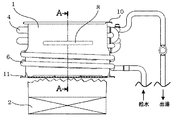
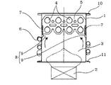
1は板金材を折り曲げて角筒状に形成したドラムで、給湯装置の熱交換器を構成するものであり、内部下方には燃焼バーナ2が上向きに備えられ、内方は下方から上方に熱気が通過する燃焼室3を形成するものである。
Next, an embodiment of the present invention will be described with reference to the drawings.
4は絞り加工によって細くされたドラム1上部内方に備えられたフィンパイプで、外周には複数枚のフィン5が固着されドラム1を貫通して設置され、燃焼バーナ2の燃焼で発生する熱気との熱交換を積極的に行うものである。
6はドラム1下部外周に巻回された周パイプで、上端を前記フィンパイプ4と連通すると共に下端を市水に連通して、内方に給水を流通させてドラム1外周を冷却しながら加熱されるもので、冷却効果を高めるためにドラム1とはろう付けで固着されている。
6 is a peripheral pipe wound around the lower outer periphery of the
7は前記フィンパイプ4下部のフィン5とドラム1の前後壁との間に設けられた帯状の断熱材で、熱気が集中するフィン5下部からの熱伝導で、ドラム1の前後壁上部の加熱による焼損を防止するものである。
7 is a strip-shaped heat insulating material provided between the
8は前記断熱材7下端のドラム1前後壁に備えられた案内手段で、ドラム1前後壁に内方に突出するように一体成形で成形された2つの案内突起9から構成され、該ドラム1内壁に沿って上昇する下方の燃焼バーナ2からの熱気をドラム1中央に案内すると共に、断熱材7下端が直接熱気にさらされることによる焼損も防止するものであり、断熱材7と案内手段8との相乗効果によりドラム1の過熱防止と熱交換器効率の向上を図ることが出来るものである。
10はドラム1上端の上フランジ、11はドラム1下端の下フランジである。
次にこの一実施形態の作用について説明すれば、今給湯栓(図示せず)を開栓してフィンパイプ4及び周パイプ6内に給水の流れが発生することで、燃焼バーナ2が燃焼を開始するものである。
Next, the operation of this embodiment will be described. The hot water tap (not shown) is now opened, and the flow of feed water is generated in the
そしてこの燃焼バーナ2の燃焼で発生した熱気は、ドラム1内壁に沿って上昇してドラム1下部を加熱するが、このドラム1下部には周パイプ6が巻回されているので、該周パイプ6内を流れる給水により冷却されると共に、給水は加熱されて温水となってフィンパイプ4内に流入する。
The hot air generated by the combustion of the
次にドラム1下部からの熱気は、ドラム1上部のフィンパイプ4部分に流れ込むが、特に熱気が最初に流れ込み集中するフィンパイプ4下部のフィン5とドラム1内壁との間には、断熱材7が備えられて熱伝導が遮断されることで、ドラム1内壁が過熱されて焼損する心配がなく、逆にこの遮断された熱はフィンパイプ4内を流通する温水に付加されることとなり、熱交換効率も向上するものであ。
Next, the hot air from the lower part of the
更にドラム1下部の内壁に沿って上昇して来る熱気は、断熱材7下端の案内手段8によってドラム1中央に案内されると共に、断熱材7下端が直接熱気にさらされることによる焼損も防止するものであり、断熱材7と案内手段8との相乗効果によりドラム1の過熱防止と、熱気が中央に拡散されることにより熱交換器効率の向上を図ることが出来るものである。
Further, the hot air rising along the inner wall of the lower part of the
又前記案内手段8をドラム1前後壁の内壁に形成された2つの案内突起9から構成したことで、案内突起9はドラム1と一体成形されているので、安価で済むと共に強固であり、長期に渡って良好な作用を維持出来るものである。
Further, since the guide means 8 is composed of the two
1 ドラム
4 フィンパイプ
5 フィン
6 周パイプ
7 断熱材
8 案内手段
DESCRIPTION OF
Claims (2)
Priority Applications (1)
| Application Number | Priority Date | Filing Date | Title |
|---|---|---|---|
| JP2016101390A JP6633452B2 (en) | 2016-05-20 | 2016-05-20 | Water heater |
Applications Claiming Priority (1)
| Application Number | Priority Date | Filing Date | Title |
|---|---|---|---|
| JP2016101390A JP6633452B2 (en) | 2016-05-20 | 2016-05-20 | Water heater |
Publications (2)
| Publication Number | Publication Date |
|---|---|
| JP2017207259A true JP2017207259A (en) | 2017-11-24 |
| JP6633452B2 JP6633452B2 (en) | 2020-01-22 |
Family
ID=60415989
Family Applications (1)
| Application Number | Title | Priority Date | Filing Date |
|---|---|---|---|
| JP2016101390A Active JP6633452B2 (en) | 2016-05-20 | 2016-05-20 | Water heater |
Country Status (1)
| Country | Link |
|---|---|
| JP (1) | JP6633452B2 (en) |
Citations (7)
| Publication number | Priority date | Publication date | Assignee | Title |
|---|---|---|---|---|
| JPS6066989U (en) * | 1983-10-14 | 1985-05-13 | 三洋電機株式会社 | Heat exchanger for water heater |
| JPH0519857U (en) * | 1991-08-23 | 1993-03-12 | パロマ工業株式会社 | Heat exchanger |
| JPH07253281A (en) * | 1994-03-16 | 1995-10-03 | Matsushita Electric Ind Co Ltd | Heat exchanger |
| JPH09292161A (en) * | 1996-04-25 | 1997-11-11 | Corona Corp | Heat exchanger of hot water supply apparatus |
| JP2000314561A (en) * | 1999-04-28 | 2000-11-14 | Toto Ltd | Heat exchanger |
| JP2001336887A (en) * | 2000-05-30 | 2001-12-07 | Noritz Corp | Heat exchanger |
| JP2002013825A (en) * | 2000-06-27 | 2002-01-18 | Noritz Corp | Assembly structure of heat exchanger |
-
2016
- 2016-05-20 JP JP2016101390A patent/JP6633452B2/en active Active
Patent Citations (7)
| Publication number | Priority date | Publication date | Assignee | Title |
|---|---|---|---|---|
| JPS6066989U (en) * | 1983-10-14 | 1985-05-13 | 三洋電機株式会社 | Heat exchanger for water heater |
| JPH0519857U (en) * | 1991-08-23 | 1993-03-12 | パロマ工業株式会社 | Heat exchanger |
| JPH07253281A (en) * | 1994-03-16 | 1995-10-03 | Matsushita Electric Ind Co Ltd | Heat exchanger |
| JPH09292161A (en) * | 1996-04-25 | 1997-11-11 | Corona Corp | Heat exchanger of hot water supply apparatus |
| JP2000314561A (en) * | 1999-04-28 | 2000-11-14 | Toto Ltd | Heat exchanger |
| JP2001336887A (en) * | 2000-05-30 | 2001-12-07 | Noritz Corp | Heat exchanger |
| JP2002013825A (en) * | 2000-06-27 | 2002-01-18 | Noritz Corp | Assembly structure of heat exchanger |
Also Published As
| Publication number | Publication date |
|---|---|
| JP6633452B2 (en) | 2020-01-22 |
Similar Documents
| Publication | Publication Date | Title |
|---|---|---|
| JP6285564B2 (en) | Heat exchanger | |
| CN107966046B (en) | Finned tube type heat exchanger and combustion device with same | |
| EP3128251A1 (en) | Heat exchanger | |
| JP6831206B2 (en) | Fin tube type heat exchanger and combustion device equipped with this heat exchanger | |
| RU2011118723A (en) | SMALL COGENERATOR SECONDARY BOILER RELEASE DEVICE AND SHELL ASSEMBLY FORMING THE SMALL CENERATOR SECONDARY BOILER EXCHANGE | |
| KR20150028468A (en) | Instantaneous heating apparatus for electricity | |
| JP2008209058A (en) | Heat exchange burner | |
| US11162710B2 (en) | Heat exchanger including flue flow path guide system | |
| JP6633452B2 (en) | Water heater | |
| EP2724106B1 (en) | Heat exchanger tube set | |
| WO2009110509A1 (en) | Heating apparatus | |
| US10724762B2 (en) | Heat exchanger including flue flow path guide system | |
| KR101151538B1 (en) | Heat exchanger having combustion chamber and combustor containing thereof | |
| JP5268971B2 (en) | Stove burner and stove | |
| RU2270401C2 (en) | Burner for heater and automobile heater | |
| JP6834772B2 (en) | Hot water device | |
| JP4350697B2 (en) | Small heat exchanger | |
| US5913289A (en) | Firetube heat exchanger with corrugated internal fins | |
| KR20140025881A (en) | Pen Coil Heater Using Heat Pipe | |
| JP5192207B2 (en) | Heating device | |
| KR101327384B1 (en) | Unitized heat radiator | |
| JP2019066117A (en) | Heat exchanger and water heater | |
| JP6449190B2 (en) | Gas water heater | |
| KR100417209B1 (en) | Heat exchanger of gas boiler | |
| JP4095539B2 (en) | Long surface combustion burner |
Legal Events
| Date | Code | Title | Description |
|---|---|---|---|
| A621 | Written request for application examination |
Free format text: JAPANESE INTERMEDIATE CODE: A621 Effective date: 20181010 |
|
| A977 | Report on retrieval |
Free format text: JAPANESE INTERMEDIATE CODE: A971007 Effective date: 20190725 |
|
| A131 | Notification of reasons for refusal |
Free format text: JAPANESE INTERMEDIATE CODE: A131 Effective date: 20190730 |
|
| A521 | Request for written amendment filed |
Free format text: JAPANESE INTERMEDIATE CODE: A523 Effective date: 20190926 |
|
| TRDD | Decision of grant or rejection written | ||
| A01 | Written decision to grant a patent or to grant a registration (utility model) |
Free format text: JAPANESE INTERMEDIATE CODE: A01 Effective date: 20191210 |
|
| A61 | First payment of annual fees (during grant procedure) |
Free format text: JAPANESE INTERMEDIATE CODE: A61 Effective date: 20191212 |
|
| R150 | Certificate of patent or registration of utility model |
Ref document number: 6633452 Country of ref document: JP Free format text: JAPANESE INTERMEDIATE CODE: R150 |
|
| R250 | Receipt of annual fees |
Free format text: JAPANESE INTERMEDIATE CODE: R250 |
|
| R250 | Receipt of annual fees |
Free format text: JAPANESE INTERMEDIATE CODE: R250 |