JP2017206269A - Beverage container - Google Patents
Beverage container Download PDFInfo
- Publication number
- JP2017206269A JP2017206269A JP2016098129A JP2016098129A JP2017206269A JP 2017206269 A JP2017206269 A JP 2017206269A JP 2016098129 A JP2016098129 A JP 2016098129A JP 2016098129 A JP2016098129 A JP 2016098129A JP 2017206269 A JP2017206269 A JP 2017206269A
- Authority
- JP
- Japan
- Prior art keywords
- packing
- lid
- inner plug
- posture
- lid body
- Prior art date
- Legal status (The legal status is an assumption and is not a legal conclusion. Google has not performed a legal analysis and makes no representation as to the accuracy of the status listed.)
- Granted
Links
Images


Abstract
Description
本発明は、パッキンが取付けられたパッキン取付け姿勢で、飲料容器本体の容器口部に装着可能とされ、当該装着状態で飲料容器本体内からの液漏れを防止する密栓状態を実現する蓋体を備えた飲料容器に関する。 The present invention provides a lid that realizes a tightly-sealed state that can be attached to a container mouth portion of a beverage container body in a packing attachment posture to which the packing is attached, and prevents liquid leakage from the beverage container body in the attached state. The present invention relates to a beverage container provided.
飲料を収納する飲料容器本体と、この飲料容器本体の容器口部に装着される蓋体とを備えた飲料容器はよく知れている。
飲料容器本体に対する蓋体の装着に際しては、通常、飲料容器本体の外側部に雄側螺合部を設け、蓋体の内側部に雌側螺合部を設けて、蓋体を飲料容器本体に装着できる構造が採用される(特許文献1、特許文献2)。
A beverage container provided with a beverage container main body for storing a beverage and a lid attached to a container mouth portion of the beverage container main body is well known.
When the lid is attached to the beverage container body, the male container is usually provided on the outer side of the beverage container body, the female screw part is provided on the inner side of the lid body, and the lid body is attached to the beverage container body. A structure that can be mounted is employed (Patent Document 1, Patent Document 2).
蓋体には、中栓が固定取付け可能とされ、中栓の容器口部側にパッキン取付け部を設け、このパッキン取付け部にパッキンを取付けたパッキン取付け姿勢で、蓋体を飲料容器本体に装着して容器口部を密栓する。これにより、飲料容器本体から飲料が漏れるのを防止することができる。即ち、正常な使用状態である、パッキンが取付けられた蓋体は、飲料容器本体の容器口部に装着されて密栓状態を実現する。 A lid can be fixedly attached to the lid, and a packing attachment part is provided on the container mouth side of the closure, and the lid is attached to the beverage container body in a packing attachment posture with the packing attached to the packing attachment part. Then seal the container mouth. Thereby, it can prevent that a drink leaks from a drink container main part. In other words, the lid with the packing attached, which is in a normal use state, is attached to the container mouth portion of the beverage container body to realize a sealed state.
特許文献1においては、パッキン16が、この目的のために設けられるパッキンであり、パッキン16はパッキン押さえつば14の下に設けられたパッキン装着つば15に取付けられる。特許文献2に開示の飲料容器の栓体にあっては、パッキン33がこの目的で設けられている。パッキン33はシール部材装着部32に取付けられる。
これらパッキン16、33の取外し、取付けに関し、パッキン取付け部近傍の形態が変わることはない。
In Patent Document 1, the packing 16 is a packing provided for this purpose, and the packing 16 is attached to a packing mounting collar 15 provided under the packing pressing collar 14. In the beverage container stopper disclosed in Patent Document 2, a packing 33 is provided for this purpose. The packing 33 is attached to the seal
With regard to the removal and attachment of these packings 16 and 33, the form in the vicinity of the packing attachment portion does not change.
これら文献に開示の技術は共に蓋体を複数の部品で構成し、蓋体の分解・組立を可能とし、各部品の洗浄性を向上することで蓋体を清潔に保つことができ、そのお手入れ性も良好である。お手入れに際しては、パッキン(所謂、栓パッキン)も取外しが可能となっている。 Both of the technologies disclosed in these documents make up the lid with a plurality of parts, allowing the lid to be disassembled and assembled, and improving the cleanability of each part to keep the lid clean. Care is also good. When cleaning, a packing (so-called plug packing) can also be removed.
これら特許文献1、2に開示される分解構造を有する蓋体は、お手入れ性が向上する反面、分解・組立のための作業が生じ、蓋体の組立時に部品の組み忘れを生じさせるという問題があった。 The lid body having the disassembled structure disclosed in these Patent Documents 1 and 2 improves the careability, but on the other hand, the work for disassembling and assembling occurs, causing forgetting to assemble the parts when the lid is assembled. was there.
そこで、中栓の組み忘れを防止するために、中栓が組付けられていない状態では、蓋体を飲料容器本体に装着できないような構成を採用している。 Therefore, in order to prevent forgetting to assemble the inner stopper, a configuration is adopted in which the lid cannot be attached to the beverage container body when the inner stopper is not assembled.
しかしながら、栓パッキンも取外されている場合、この栓パッキンを中栓に取付けることを忘れることがある。
栓パッキンは、容器口部に装着する前に蓋体を裏返して目で見なければ、それ以降、栓パッキンの取付け忘れがあったか否かを使用者が知る機会がない。このため使用時に、栓パッキンの取付け忘れに起因する漏れ等の問題が発生する場合がある。即ち、中栓自体は蓋体内に取り付けられているが、パッキンの取付けが忘れられた場合、液漏れを防止できる密栓状態が実現できない。
However, if the plug packing is also removed, it may be forgotten to attach the plug packing to the inner plug.
If the lid packing is turned over before it is attached to the container mouth, the user has no opportunity to know whether or not he / she has forgotten to install the plug packing. For this reason, problems such as leakage due to forgetting to install the plug packing may occur during use. That is, the inner plug itself is attached to the inside of the lid, but when the packing is forgotten, a sealed state that prevents liquid leakage cannot be realized.
本発明の主たる課題は、この実情に鑑み、飲料容器本体の容器口部を密栓するためのパッキンの取付けを確実なものとし、パッキンの取付け忘れに伴って漏れ等、不測の問題が発生することがない飲料容器を提供する点にある。 In view of this situation, the main problem of the present invention is to ensure that the packing for sealing the container mouth of the beverage container main body is securely attached, and that unexpected problems such as leakage occur when the packing is forgotten. It is the point which provides the beverage container which does not have.
本発明の特徴構成は、パッキンが取付けられたパッキン取付け姿勢で、飲料容器本体の容器口部に装着可能とされ、当該装着状態で飲料容器本体内からの液漏れを防止する密栓状態を実現する蓋体を備えた飲料容器であって、
前記蓋体が、前記パッキンが取外されたパッキン取外し姿勢において、前記パッキン取付け姿勢とは異なる姿勢を取る構成で、
前記パッキン取外し姿勢において、前記蓋体の前記容器口部への装着に関し、前記密栓状態を実現する装着が不可とされる点にある。
The characteristic configuration of the present invention realizes a tightly plugged state in which the packing can be attached to the container mouth portion of the beverage container main body in a packing attachment posture to which the packing is attached, and prevents liquid leakage from the beverage container main body in the attached state. A beverage container with a lid,
In the configuration where the lid body takes a posture different from the packing attachment posture in the packing removal posture where the packing is removed,
In the packing removal posture, regarding the mounting of the lid to the container mouth, the mounting to realize the sealed state is not possible.
本構成によれば、パッキン取外し姿勢に蓋体がある状態で、蓋体を容器口部に装着して密栓状態を実現することができない。飲料容器の使用者は、蓋体を装着しようとする段階で、飲用容器本体に対して蓋体自体が組付けられない(この場合は当然に密栓状態とはならない)、或いは密栓状態まで到達できないことを認識して、パッキンを取外したままである可能性があること、取付ける必要があることを想起できる。結果、パッキンが取付けられないまま、蓋体が飲料容器本体に装着され、飲料容器内部から液漏れが生じる等の問題を解消できる。 According to this configuration, in a state where the lid is in the packing removal posture, the lid cannot be attached to the container mouth portion to realize a sealed state. The user of the beverage container cannot attach the lid itself to the main body of the beverage container at the stage where the lid is to be attached (in this case, of course, it is not sealed), or cannot reach the sealed state. Recognizing this, it can be recalled that the packing may remain removed and needs to be installed. As a result, it is possible to solve the problem that the lid is attached to the beverage container main body without the packing being attached and the liquid leaks from the inside of the beverage container.
本発明の特徴構成は、前記パッキン取外し姿勢において、前記蓋体が前記容器口側に装着することを阻止する阻止部が前記蓋体に備えられている点にある。 The characteristic configuration of the present invention is that the lid body is provided with a blocking portion that prevents the lid body from being mounted on the container mouth side in the packing removal posture.
本構成よれば、蓋体を飲料容器本体に装着しようとする段階で、阻止部が蓋体の前記容器口側への装着を阻止することで、パッキン取外し姿勢での蓋体装着阻止を実現できる。 According to this configuration, at the stage of attaching the lid body to the beverage container body, the blocking portion prevents the lid body from being attached to the container mouth side, thereby preventing the lid body from being attached in the packing removal posture. .
本発明の特徴構成は、前記蓋体と前記容器口部とが中心軸をともにする円筒状部材として構成されており、前記阻止部が前記中心軸に沿った前記蓋体の前記容器口側への移動を阻止する点にある。 The characteristic configuration of the present invention is configured as a cylindrical member in which the lid body and the container mouth portion share a central axis, and the blocking portion extends toward the container mouth side of the lid body along the central axis. The point is to prevent the movement of.
本構成よれば、容器口部に蓋体を装着しようとする段階で、阻止部が共通中心軸に沿った軸方向移動を阻止するため、蓋体の装着不可状態により、パッキンが取付けられない状態で飲料容器が使用されることはない(従って、漏れ等の問題は発生しない)。さらに、蓋体を装着できないため、パッキンの取付け忘れがある可能性に使用者が思い到ることができる。 According to this configuration, when the lid is about to be attached to the container mouth portion, the blocking portion prevents axial movement along the common central axis, so that the packing cannot be attached due to the lid being unmountable. In this case, the beverage container is not used (therefore no problems such as leakage). In addition, since the lid cannot be attached, the user can think of the possibility of forgetting to install the packing.
本発明の特徴構成は、前記蓋体が、前記容器口部に螺合する螺合部を備えた蓋本体と、
前記パッキンが取付けられるパッキン取付け部が設けられ、当該蓋本体に固定可能とされた中栓と、前記パッキンが前記パッキン取付け部に取付けられることによって前記蓋本体に対して前記中栓を固定する前記パッキン取付け姿勢となり、前記パッキンが前記パッキン取付け部から取外されることによって前記中栓を前記蓋本体から解除したパッキン取外し姿勢となる固定制御手段とが備えられている点にある。
A characteristic configuration of the present invention is that the lid body includes a screw body that is screwed into the container mouth portion;
A packing attaching portion to which the packing is attached is provided, and an inner plug that can be fixed to the lid main body, and the packing is attached to the packing attaching portion to fix the inner plug to the lid main body. There is a fixing control means that is in a packing mounting posture, and has a packing removal posture in which the inner plug is released from the lid body when the packing is removed from the packing mounting portion.
本構成によれば、本来、パッキンを取付けた中栓が蓋本体に固定される構成の蓋体に、固定制御手段を設けることで、パッキンが取外された状態では、蓋本体から中栓が解除され、実質的に固定できない。例えば、後述する実施形態で示すように、蓋本体に対して中栓が周方向で回転できる状態となる。結果、この解除状態により使用者はパッキンが取付けられていない可能性があることを知ることができ、パッキンを取付ける必要があることを認識できる。 According to this configuration, by providing the fixing control means on the lid body in which the inner plug to which the packing is attached is originally fixed to the lid body, the inner plug is removed from the lid body when the packing is removed. It is released and cannot be fixed substantially. For example, as shown in an embodiment described later, the inner plug can rotate in the circumferential direction with respect to the lid body. As a result, this released state allows the user to know that there is a possibility that the packing is not attached, and can recognize that it is necessary to install the packing.
本発明の特徴構成は、前記固定制御手段が、前記中栓に設けられ、パッキン取付け姿勢とパッキン取外し姿勢との間で揺動する揺動部材と、前記蓋本体に設けられる突出部と、前記揺動部材の揺動に伴ってその位置を、パッキン取付け姿勢において前記突出部が当該揺動部材と係合固定可能となる位置移動を許容する許容位置と、パッキン取外し姿勢において前記突出部が当該揺動部材と係合固定可能となる位置移動を規制する規制位置と、に変える移動規制用揺動端部が前記蓋体に備えられている点にある。 The characteristic configuration of the present invention is characterized in that the fixing control means is provided in the inner plug and swings between a packing attachment posture and a packing removal posture, a protrusion provided in the lid body, As the swinging member swings, the position of the swinging member is allowed to move so that the protruding portion can be engaged and fixed with the swinging member in the packing mounting posture, and the protruding portion is moved to the position in the packing removal posture. The movement body is provided with a movement restricting rocking end portion for changing to a restriction position for restricting the movement of the position of the rocking member to be engaged and fixed.
蓋本体に対する中栓の固定を制御する(係合固定可能若しくは係合固定不可とする)固定制御手段を、蓋本体側に設ける突出部と中栓側に設ける揺動部材とで構成し、この揺動部材に移動規制用揺動端部を設けることで、揺動部材の揺動に伴って、これまで説明してきた姿勢変更を実現し、さらに固定制御を実現できる。 The fixing control means for controlling the fixing of the inner plug to the lid main body (engagement fixing or non-engagement fixing) is constituted by a protrusion provided on the lid main body side and a swing member provided on the inner plug side. By providing the movement regulating rocking end portion on the rocking member, it is possible to realize the posture change described so far as the rocking member rocks, and to realize the fixed control.
本発明の特徴構成は、
前記蓋本体と前記中栓とが中心軸を共有する円筒状部材として構成され、
前記パッキン取外し姿勢から前記パッキン取付け姿勢への姿勢変更において、前記揺動部材の前記移動規制用揺動端部が径方向に位置移動するとともに、前記突出部が前記中心軸の軸方向で位置移動する点にある。
The characteristic configuration of the present invention is as follows:
The lid body and the inner plug are configured as a cylindrical member sharing a central axis,
When the posture is changed from the packing removal posture to the packing mounting posture, the rocking end for movement restriction of the rocking member moves in the radial direction, and the protruding portion moves in the axial direction of the central axis. There is in point to do.
本構成によれば、移動規制用揺動端部と突出部とにより固定制御手段を構成する場合に、移動規制用揺動端部の径方向移動により、当該部位が許容位置と規制位置との間で位置移動する構成を採用し、中心軸の軸方向に沿って近接してくる突出部との干渉・非干渉を実現できる。 According to this configuration, when the fixed control means is configured by the movement restricting rocking end and the protruding portion, the movement of the movement restricting rocking end in the radial direction causes the portion to move between the allowable position and the restricting position. It is possible to realize interference / non-interference with the protrusions that are close to each other along the axial direction of the central axis.
本発明の特徴構成は、
前記蓋本体と前記中栓とが中心軸を共有する円筒状部材として構成され、
前記揺動部材が前記パッキン取付け姿勢を取る状態で、
前記蓋本体が前記中栓に対して前記中心軸周りに回転して又は中心軸方向に移動して、前記中栓が前記蓋本体に固定される点にある。
The characteristic configuration of the present invention is as follows:
The lid body and the inner plug are configured as a cylindrical member sharing a central axis,
In a state where the swing member takes the packing mounting posture,
The lid body rotates around the central axis with respect to the inner plug or moves in the direction of the central axis, so that the inner plug is fixed to the lid main body.
本構成によれば、移動規制用揺動端部と突出部とにより固定制御手段を構成する場合に移動規制用揺動端部が許容位置にある状態で、蓋本体が中栓に対して中心軸周りに回転される、又は軸方向に移動されることにより、蓋本体に対する中栓の固定を実現できる。 According to this configuration, when the fixed control means is configured by the movement restricting rocking end and the protrusion, the lid body is centered with respect to the inner plug while the movement restricting rocking end is in the allowable position. The inner plug can be fixed to the lid body by being rotated around the axis or moved in the axial direction.
本発明の特徴構成は、
前記固定動作に関し、前記中栓に対する前記蓋本体の移動方向先端側における、
前記移動規制用揺動端部より先端側に、固定用端部が備えられ、
前記移動により、前記突出部と前記固定用端部とが係合する点にある。
The characteristic configuration of the present invention is as follows:
Regarding the fixing operation, on the distal end side in the movement direction of the lid body with respect to the inner plug,
A fixing end is provided on the tip side from the movement regulating swinging end,
By the movement, the protrusion and the fixing end are engaged.
本構成によれば、移動規制用揺動端部と突出部とにより固定制御手段を構成する場合に、移動規制用揺動端部に加えて、蓋本体の回転移動方向先端側に固定用端部を備えて、この固定用端部と突出部との間で係合固定を実現できる。 According to this configuration, when the fixing control means is configured by the movement restricting rocking end and the protrusion, in addition to the movement restricting rocking end, the fixing end is provided at the distal end side in the rotational movement direction of the lid body. It is possible to achieve engagement and fixation between the fixing end and the protruding portion.
本発明の特徴構成は、
前記蓋体が、前記容器口部に螺合する螺合部を備えた蓋本体と、当該蓋本体に固定される中栓とを備えて構成されるとともに、前記パッキンが取付けられるパッキン取付け部を前記中栓に備えて構成され、
前記パッキン取外し姿勢において、前記蓋本体と前記中栓とは両者間の相対位置関係が変化する非固定状態になっている点にある。
The characteristic configuration of the present invention is as follows:
The lid body includes a lid main body having a screwing portion that is screwed into the container mouth portion, and an inner plug fixed to the lid main body, and a packing attaching portion to which the packing is attached. Configured for the inner plug,
In the packing removal posture, the lid main body and the inner plug are in an unfixed state in which the relative positional relationship between the two changes.
本構成によれば、パッキンが取付けられていないパッキン取外し姿勢においては、蓋本体と中栓とは非固定状態になっており、例えば両者がある程度、組み合わされている状態でも、両者間は非固定状態になっているため、この非固定状態を使用者は組付け時に容易に認識でき、パッキンの取付け忘れを想起できる。 According to this configuration, in the packing removal posture in which no packing is attached, the lid main body and the inner plug are in an unfixed state. For example, even when both are combined to some extent, the two are not fixed. Since it is in a state, the user can easily recognize this non-fixed state when assembling, and can recall forgetting to install the packing.
本発明の特徴構成は、先に説明した本発明独特の前記固定制御手段が、
前記中栓に備えられる揺動軸周りに揺動自在な揺動部材と、前記蓋本体に備えられる突出部とから構成され、
前記蓋本体と前記中栓とが中心軸を共有する円筒状部材として構成され、
前記パッキン取外し姿勢において、前記蓋本体と前記中栓とは両者間の相対位置関係が変化する非固定状態になっており、前記パッキン取付け姿勢における前記揺動部材の姿勢位置で、前記蓋本体が前記中栓に対して、前記中心軸周りに回転して、前記中栓が前記蓋本体に固定されることにある。
The characteristic configuration of the present invention is that the fixed control means unique to the present invention described above is
It is composed of a swinging member swingable around a swinging shaft provided in the inner plug, and a protrusion provided in the lid body.
The lid body and the inner plug are configured as a cylindrical member sharing a central axis,
In the packing removal posture, the lid body and the inner plug are in an unfixed state in which the relative positional relationship between the two changes, and the lid body is in the posture position of the swinging member in the packing attachment posture. The inner plug is fixed to the lid body by rotating around the central axis with respect to the inner plug.
本構成によれば、パッキン取外し姿勢では、蓋本体と中栓が非固定状態になっているため、実質的に、使用者が蓋体を取付ける操作に入り難い。これに対して、パッキン取付け姿勢を取る状態で、蓋本体と中栓との間での固定を完了できるため、パッキン取付けに伴った蓋体の取付けに移ることができる。 According to this configuration, in the packing removal posture, since the lid main body and the inner plug are in an unfixed state, it is substantially difficult for the user to enter the operation of attaching the lid. On the other hand, since the fixing between the lid main body and the inner plug can be completed in a state where the packing mounting posture is taken, it is possible to shift to the mounting of the lid accompanying the packing mounting.
本発明の特徴構成として、前記蓋体が、前記容器口部に螺合する螺合部を備えた蓋本体と、当該蓋本体に固定される中栓とを備えて構成されるとともに、前記パッキンが取付けられるパッキン取付け部を前記中栓に備えて構成され、
前記パッキン取外し姿勢において、蓋体天面と前記中栓の天面とが異なった位置に位置され、面間に段差を有することも可能である。
As a characteristic configuration of the present invention, the lid body includes a lid body provided with a screwing portion screwed into the container mouth portion, and an inner plug fixed to the lid body, and the packing The inner plug is provided with a packing attachment portion to which is attached,
In the packing removal posture, the top surface of the lid body and the top surface of the inner plug are located at different positions, and a step may be provided between the surfaces.
この構成を採用すると、蓋体天面と中栓の天面との間で段差がある状態までしか、組付かない場合、使用者は、この状況で、パッキンが取外された状態にあることを意識して、その原因を探求し、解決することができる(パッキンが取外されている場合は、パッキンを取付けることができる)。 If this configuration is adopted, the user must be in a state where the packing has been removed in this situation when there is only a step between the top of the lid and the top of the plug. The cause can be investigated and solved (the packing can be attached if the packing is removed).
以上説明したように、飲料容器本体の容器口部を密栓するためのパッキンの取付けを確実なものとでき、パッキンの取付け忘れに伴って不測の漏れ等が発生することがない飲料容器を得られた。 As described above, it is possible to reliably install the packing for sealing the container mouth of the beverage container main body, and to obtain a beverage container that does not cause unexpected leakage or the like due to forgetting to install the packing. It was.
本発明の実施形態について図面に基づいて説明する。
図1から図7が第1実施形態の図面であり、図8は別実施形態の図面である。
Embodiments of the present invention will be described with reference to the drawings.
1 to 7 are drawings of the first embodiment, and FIG. 8 is a drawing of another embodiment.
本発明に係る飲料容器100は、飲料容器本体101と、この飲料容器本体101に螺合装着される蓋体102とを備えて構成され、蓋体102は、蓋体102にパッキン10を取り付けた状態で、飲料容器本体101の容器口部101aに装着可能とされ、当該装着状態で飲料容器本体101内からの液漏れを防止する密栓状態が実現する。
A
この装着操作は、蓋体102を飲料容器本体101の容器口部101aの外周側に設けられた雄側螺合部101bに螺合させることで行う。
図1は、螺合装着操作を完了した状態における縦断面図である。
This mounting operation is performed by screwing the
FIG. 1 is a longitudinal sectional view in a state where the screwing operation is completed.
図1からも判明するように、飲料容器本体101は、その上部に容器口部101aが設けられ、この容器口部101aの最小径部位が蓋体102に取付けられたパッキン10により密栓される密栓部101cとされている。パッキン10は通用の円環状を成す栓パッキンである。
As can be seen from FIG. 1, the beverage container
図1、図2からも判明するように、蓋体102は、容器口部101aの雄側螺合部101bに螺合する雌側螺合部20aを内側面に備えた蓋本体20と、当該蓋本体20に固定される中栓30とを備えて構成されている。
As can be seen from FIGS. 1 and 2, the
蓋本体20は、その天面部位に、デコレーションプレート21を挟んだ状態でプレートホルダー22が係合されており、その内部に中栓30が係合固定される。プレートホルダー22の蓋本体天面22cが、中栓キャップ32の天面32aとともに蓋体102の「天面」となる。そこで本発明では後者である中栓キャップ32の天面32aを「天面の一部」と呼ぶ。
The lid
中栓30は、中栓本体31と中栓キャップ32を備え、中栓本体31の上部が蓋本体20に係合する構造とされており、中栓本体31の下部にパッキン10が取付けられるパッキン取付け部31aが設けられている(図1参照)。
The
本発明の特徴は、蓋体102にパッキン10が取付けられたパッキン取付け姿勢において蓋体102を飲料容器本体101に装着することで密栓状態が実現され、蓋体102からパッキン10が取外された(換言するとパッキン10が取付けられていない)パッキン取外し姿勢において蓋体102を飲料容器本体101に装着したとしても、密栓状態の実現が不可とされる点にある。
第1実施形態では、中栓30の蓋本体20に対する固定・非固定に対応して、密栓状態の実現・実現不可が決定する。即ち、中栓30が蓋本体20に固定された固定状態で密栓状態が実現でき、中栓30が蓋本体20に固定されていない非固定状態では密栓状態を実現できない。
A feature of the present invention is that the
In the first embodiment, corresponding to whether the
ここで言う、中栓30の蓋本体20に対する固定は、中栓30が蓋本体20に対して、その中心軸Zに沿った軸方向Z1で当接し、さらに中栓30がその中心軸Z周りに回転して完了する。
Here, the
以下、これらの構成に関して、図3〜図7を使用して説明する。
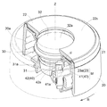
図3、図4は、パッキン取外し姿勢における一部断面斜視図(図3)、縦断面図(図4(a))、横断面図(図4(b))である。
図4(b)は、蓋体102をその底面側から視た底面視図であり、同図に示すIVa−IVaの断面を図4(a)に示している。
このパッキン取外し姿勢においては、中栓30と蓋本体20とは軸方向Z1で離間されており、固定できない。
Hereinafter, these configurations will be described with reference to FIGS.
3 and 4 are a partial cross-sectional perspective view (FIG. 3), a vertical cross-sectional view (FIG. 4A), and a horizontal cross-sectional view (FIG. 4B) in the packing removal posture.
FIG. 4B is a bottom view when the
In this packing removal posture, the
図5、図6は、パッキン取付け姿勢における一部断面斜視図(図5)、縦断面図(図6(a))、横断面図(図6(b))である。
図6(b)も、蓋体102をその底面側から視た底面視図であり、同図に示すVIa−VIaの断面を図6(a)に示している。
このパッキン取付け姿勢においては、中栓30と蓋本体20とは軸方向Z1で当接するが、中心軸Zの周方向Rへの回転操作を待つ状態、及び、相対回転されて固定された状態の両方を取ることができる。
図7は、相対回転操作を完了し、中栓30の蓋本体20への固定を完了した状態における要部横断面図であり、この状態の縦断面図が、先に説明した図1である。
FIGS. 5 and 6 are a partial cross-sectional perspective view (FIG. 5), a vertical cross-sectional view (FIG. 6A), and a horizontal cross-sectional view (FIG. 6B) in the packing mounting posture.
FIG. 6B is also a bottom view when the
In this packing mounting posture, the
FIG. 7 is a cross-sectional view of the main part in a state where the relative rotation operation is completed and the fixing of the
これらの図において、Zは、基本的に円筒状部材として構成される蓋体102を構成する部材(蓋本体20、デコレーションプレート21、プレートホルダー22、中栓30(中栓本体31と中栓キャップ32を含む))の中心軸を示し、Z1は中心軸Zに沿った方向を、Dはその中心軸Zの径方向を、さらに、Rは中心軸Z周りに定義され、蓋本体20に対して中栓本体31を回転固定する場合に、蓋本体20が中栓本体31に対して回動する方向を示している。図4(b)、図6(b)は底面視での要部横断面図であるため、図2等に示す方向とは逆となる。
In these drawings, Z is a member (cover
以下、まず、パッキン取付け姿勢での通用の蓋体102の組付けに関して説明する。
図2に示すように、蓋体102は、蓋本体20、中栓本体31及び中栓キャップ32が中心軸Zを共有する円筒状部材として構成される。さらに、蓋体102は、中栓本体31に設けられる中間内周側係合部31bを介して中栓本体31と中栓キャップ32が嵌合し、中栓本体31に設けられる上部外周側係合部31cを介して中栓本体31と蓋本体20とが係合固定可能に構成されている。この上部外周側係合部31cは、蓋本体20に設けられる被係合部20cに係合して、軸方向Z1下側へ抜け止めされる。
Hereinafter, first, assembly of the
As shown in FIG. 2, the
ここで、係合は、基本的には、中心軸Zに沿った軸方向Z1における相対位置の調整で両者が係合する軸方向Z1の位置関係を確保し、その後、周方向Rについて相対回動することで両者間の係合固定を完了する。 Here, the engagement basically secures the positional relationship in the axial direction Z1 in which both engage with each other by adjusting the relative position in the axial direction Z1 along the central axis Z, and then the relative rotation in the circumferential direction R. By moving, the engagement and fixation between the two are completed.
中栓の蓋本体に対する係合固定
上述したように、中栓30の蓋本体20に対する固定は、中栓30を蓋本体20に対して、その中心軸Zに沿った軸方向Z1で当接させ(軸方向位置決め)、さらにその中心軸Z周りに回転(周方向位置決め)させて実現する。
軸方向位置決めは、図3〜図6に示される周方向Rにおける中栓30と蓋本体30との相対位相関係において、上部外周側係合部31cが、蓋本体20に設けられる係合用位相調整孔20bを案内として軸方向Z1に移動し、被係合部20cより軸方向Z1側(図2において上側)に位置されて完了する。
従って、この位置決めは軸方向Z1下側への抜け止めとなる。但し、以降で示すように、この軸方向Z1の移動はパッキン10が取付けられている場合に行えるが、取外されている場合は行うことができない。
周方向位置決め固定は、図6(b)に示す中栓30と蓋本体20との相対位相関係から、図7に示す相対位相関係まで中栓30が回動することにより実現する。この周方向位置決めで、蓋本体20に備えられる突出部23が、中栓本体31に備えられる揺動部材40の固定用端部42を乗り越え、係合固定する。
As described above, the
In the axial positioning, in the relative phase relationship between the
Therefore, this positioning prevents the axial direction Z1 from coming off. However, as will be described later, the movement in the axial direction Z1 can be performed when the packing 10 is attached, but cannot be performed when the packing 10 is removed.
The circumferential positioning and fixing is realized by rotating the
図7に示すように、係合固定において、周方向にあっては、蓋本体20の内周面から下垂形成された突出部23の回動基端側は揺動部材40の固定用端部42により位置決めされ、回動先端側は先に図2において説明した被係合部20cにより位置決めされる。
As shown in FIG. 7, in the engagement and fixation, in the circumferential direction, the rotation base end side of the projecting
中栓本体と中栓キャップの係合固定
中栓キャップ32は弾性部材(例えばシリコーン素材)から構成されるため、中栓キャップ32と中栓本体31との係合は中心軸Zに沿った軸方向Z1での嵌込で行うことができる。
具体的には、中栓キャップ32を、中栓本体31の嵌入孔31hに設けた上部内周側係合部31b間に弾性収縮して嵌入させることにより、両者の嵌合(係合の一種)を完了することができる。図4、図6に示されるように、中栓キャップ32を中栓本体31に嵌合させた状態で、両者の内部が断熱空間35となる。
Engaging and fixing the inner plug body and the inner plug cap Since the
Specifically, the
中栓キャップの蓋体への係合固定
先に示したように、中栓キャップ32は弾性変形部材から構成されるため、中栓キャップ32の蓋体102への係合固定は、蓋体102を構成する蓋本体30及びプレートホルダー22の孔22b(本発明の「連通孔」)に弾性収縮させて嵌入することで行う。
Engagement and fixing of the inner cap cap to the lid body As described above, since the
次に、パッキン10の取付け・取外しに対応した蓋体102の飲料容器本体101に対する装着に関係する構成について説明する。
Next, a configuration related to attachment of the
図2に示すように、中栓本体31の外周、周方向所定位相位置に、中心軸Zに直交する揺動軸a周りに揺動自在な揺動部材40を設けている。
図4(a)に示すように、この揺動部材40は、その揺動軸aより下側となる、軸方向Z1基端側において付勢部材であるスプリング45より、径方向D外径側に付勢されている。
As shown in FIG. 2, a swinging
As shown in FIG. 4 (a), the swinging
図2、図3及び図5に示すように、揺動部材40は、その揺動軸aより上側となる軸方向Z1先端側に、移動規制用揺動端部41と固定用端部42とを備えている。
As shown in FIGS. 2, 3, and 5, the
移動規制用揺動端部41の横断面は、周方向R基端側で径方向に長く、周方向R先端側において径方向に短く構成されている。従って、この移動規制用揺動端部41はその内径側・周方向R先端側に向かうに従って外径側に位置する案内傾斜面41aを有する。
この周方向Rは、上述のように、中心軸Z周りに定義され、中栓本体31に対して蓋本体20を回転固定する場合に、蓋本体20が中栓本体31に対して回動する方向であり、蓋本体20装着時の螺合方向である(以下、同じ)。
The cross section of the movement restricting rocking
The circumferential direction R is defined around the central axis Z as described above, and the
一方、固定用端部42の横断面は、周方向R基端側で径方向に短く、周方向R先端側で径方向に長く構成されている。従って、この固定用端部42はその外径側・周方向R先端側に向かうに従って外径側に張り出した案内傾斜面42aを有する。
On the other hand, the cross section of the fixing
図3から図6に示すように、蓋本体20の内周、周方向所定位相位置に、下方(中栓本体31側)に突出する突出部23が設けられている。
この突出部23の横断面は、周方向R基端側において径方向に長く、周方向R先端側において径方向に短く構成されている。結果、この突出部23はその外径側に案内傾斜面23aを有する。
As shown in FIGS. 3 to 6, a protruding
The cross section of the projecting
そして、揺動部材40は、先に説明した移動規制用揺動端部41と固定用端部42との間に、前記突出部23が蓋本体20の回動に伴って進入可能な中間進入部dが設けられている(図2、図3参照)。
The
以上の構成を採用することにより、第1実施形態の飲料容器100では、固定制御手段Mを、中栓30と蓋本体20との間に設けていることとなる。図3から図7を使用する説明では、中栓30の蓋本体20に対する固定過程で説明を進めるが、この過程での固定制御手段Mの働きは、パッキン取付け姿勢において中栓30を蓋本体20に固定可能とし、パッキン取外し姿勢において中栓30を蓋本体20に固定不可とする機能である。
By adopting the above configuration, in the
以下、さらに説明を進める。
図3、図4に示す中栓30と蓋本体20との相対関係は、移動規制用揺動端部41が径方向D内径側に揺動した位置(規制位置)にある「パッキン取外し姿勢」であり、図5、図6に示す中栓30と蓋本体20との相対関係は、移動規制用揺動端部41が径方向外径側に揺動した位置(突出部23に対する退避位置であり、本発明の許容位置となる)にある「パッキン取付け姿勢」にある。
これらの図において、中栓30と蓋本体20との周方向R位相は同一であり、中栓30を蓋本体20の取付けようとすると、両者は、最初、この相対位相に案内される。
Hereinafter, the description will be further advanced.
The relative relationship between the
In these figures, the circumferential direction R phase of the
規制位置
前記規制位置では、移動規制用揺動端部41は、突出部23の下方に位置し、両者がそれら頭部で当接して、軸方向Z1への移動が規制される。即ち、中栓30は、蓋本体20内に充分進入することができない。この軸方向相対位置では、上部外周側係合部31cと、蓋本体20に設けられた被係合部20cとは、両者の関係において前者31cが後者20cの軸方向Z1上側に位置することができないため、両者間で周方向R移動が阻止され、結果的に、中栓30を蓋本体20の装着することができない。
Restricted Position In the restricted position, the movement restricting rocking
さらに、図3、図4(a)に示すように、この状態では、中栓キャップ32の天面32aが蓋本体天面22cに対して軸方向Z1で沈んだ引退位置を取る。換言すると段差が現れ面一とはならない。従って、この状態で、パッキン10が取付けられていないことを使用者は容易に知ることができる。
Further, as shown in FIGS. 3 and 4A, in this state, the
許容位置
前記許容位置では、移動規制用揺動端部41は、突出部23の下方から径方向D外側に退避して位置し、両者がそれら頭部で当接することはなく、軸方向Z1移動を許容される。即ち、図4(a)と図6(a)との比較において明らかなように、蓋本体20が揺動部材40側(換言すると中栓30側)下降し、中栓本体31に設けられた位置決め突起31dが蓋本体20の所定部位に当接する。
Permissible position In the permissible position, the movement restricting rocking
また、図5、図6(a)に示すように、この状態では、中栓キャップ32の天面32aが蓋本体天面22cと同一の位置まで進入可能である。但し、先に説明した中間進入部dに対して、突出部23の径方向における厚みが薄く構成されていることから、中栓30は蓋本体20に対して尚がたつくこととなる(両者間の相対位置が変化する非固定状態の一種)。結果、この状態でも、蓋本体20に対する中栓30の係合固定が完了していないことを使用者は容易に知ることができる。
As shown in FIGS. 5 and 6A, in this state, the
以上、本発明に係る固定制御手段Mは、中栓30に備えられる揺動軸周りに揺動自在な揺動部材40と、蓋本体20に備えられる突出部23とから構成されている。
As described above, the fixing control means M according to the present invention includes the swinging
また、パッキン取外し姿勢からパッキン取付け姿勢への姿勢変更においては、移動規制用揺動端部41は径方向に位置移動するとともに、突出部23が中心軸Zの軸方向で近接移動する構造となっている。
Further, in changing the posture from the packing removal posture to the packing attachment posture, the movement restricting
中栓の蓋本体への固定
以上が、中栓30が蓋本体20内に進入し当接する状況であるが、飲料容器本体101に蓋体102を取付ける場合、中栓30が蓋本体20に固定されている必要がある。
固定制御手段Mによる中栓30の蓋本体20への固定は、使用者が、この操作に際して、蓋本体20を中栓30に対して周方向Rに相対回転させる。蓋体102の横断面は、図6(b)から図7に示す状態となる。
Fixing the inner plug to the lid body The above is the situation where the
The user can fix the
図7を図6(b)と比較すると判明するように、この相対回転操作により、蓋本体20から下方に突出される突出部23は、揺動部材40の固定端部42を越えて回転され、中栓30は蓋本体20に周方向Rで係合固定される。軸方向Z1の固定は、先に説明した中栓本体31に設けられた上部外周側係合部31cと蓋本体20に設けられた被係合部20c及び中栓本体31に設けられた位置決め突起31dと蓋本体20で達成される。
この構成では、中栓30に対する蓋本体20の回転移動方向先端側における、移動規制用揺動端部41より先端側に、固定用端部42を備え、回転移動により、突出部23が固定用端部42を乗りこえて、周方向Rでの係合固定が完了することとしている。
従って、先に説明した固定制御手段Mは、揺動部材40に、当該揺動部材40の揺動に伴ってその位置を、パッキン取付け姿勢において突出部23が当該揺動部材40(具体的には固定端部42)と係合可能となる位置移動を許容する許容位置と、パッキン取外し姿勢において突出部23が当該揺動部材40と係合可能となる位置移動を規制する規制位置とに変える移動規制用揺動端部41を備えて構成されているのである。ここでの係合は、この段落に記載の係合固定である。
As can be seen from a comparison between FIG. 7 and FIG. 6B, the projecting
In this configuration, a fixing
Therefore, the fixing control means M described above has the position of the swinging
この係合固定の解除は、パッキン10の取外しに従って、係合固定が可能な位置(図7に示す位置)から固定端部42が内径側に揺動して実現される。従って、本発明の固定制御手段Mは、パッキン10がパッキン取付け部31aに取付けられることによって蓋本体20に対して中栓30を固定するパッキン取付け姿勢とし、パッキン10がパッキン取付け部31aから取外されることによって中栓30を蓋本体20から解除したパッキン取外し姿勢とする機能を備える。
The release of the engagement and fixation is realized by swinging the
以上が飲料容器100の構造及び主要機能部位の説明であるが、以下、その使用操作手順を蓋体102の組み立て、容器本体101への装着の順に説明する。
The above is the description of the structure and the main functional parts of the
蓋体の組み立て
蓋体102の組み立てにおいては、中栓30にパッキン10を取付けた後、中栓30を蓋本体20に固定し、蓋体102が容器本体101に装着可能となる。
Assembling the lid body In assembling the
中栓の組み立て
揺動部材40が取付けられた中栓本体31に、中栓キャップ32を上部側から挿入嵌合するとともに、パッキン取付け部31aにパッキン10を取付けて、中栓30の組み立てを完了する。
この完了状態において、移動規制用揺動端部41は、蓋本体20に設けられた突出部23の下降移動を許容する許容位置に位置される(図5、図6参照)。
この状態で、中栓キャップ32が上部に係合された中栓30を蓋本体20内に進入できる。このため中栓30は揺動部材40に阻害されることなく、蓋本体20に固定できる(図5、図6参照)。
Assembling the inner plug The
In this completed state, the movement restricting
In this state, the
よって、中栓30が蓋本体20に固定された蓋体102を、飲料容器本体102に装着できる。装着解除は、逆の過程を辿る。
Therefore, the
以上説明してきたように、本発明に係る飲料容器100は、パッキン10が取付けられたパッキン取付け姿勢で、飲料容器本体101の容器口部101aに装着可能とされる蓋体102を備えた飲料容器100として構成されているが、蓋体102は、パッキン10が取外されたパッキン取外し姿勢とパッキン10が取付けられた取付け姿勢とで異なる姿勢を取るように構成され、パッキン取外し姿勢において、蓋体102が容器口部101aに装着不可とされている。
As described above, the
以下、本発明の別実施形態に関して説明する。
(1)上記の第1実施形態にあっては、パッキン10が取外された状態において、蓋本体20に対する中栓30の軸方向Zへの移動を頭部の当接により阻止する移動規制用揺動端部41と固定用端部42とを揺動部材40に設けるものとしたが、先にも説明したように、中栓30の蓋本体20に対する固定は、図7に示す周方向Rの相対位相に到達した段階で完了する。
Hereinafter, another embodiment of the present invention will be described.
(1) In the first embodiment, in the state where the packing 10 is removed, for movement restriction that prevents the movement of the
ここで、図3、図4に示す状態では、固定用端部42は径方向D内径側に位置し、パッキン10の取付けに伴って揺動部材40が揺動して、初めて固定用端部42は外径側に移動し、突出部23と、この揺動状態における径方向D位置で周方向Rに干渉する位置関係となる。そして、蓋本体20の回動に伴って図7に示す係合固定が完了する。
即ち、移動規制用揺動端部41を設けず、固定用端部42のみを揺動部材40に設ける構造を想定すると、パッキン10が取外されたパッキン取外し姿勢では、中栓30は蓋本体20に対して周方向Rでフリーである。一方、パッキン10が取付けられたパッキン取付け姿勢で、中栓30はある程度、蓋本体20に組み付いているとはいえ、両者間に尚がたが存在する。そして、蓋本体20の回転操作を行って初めて、図7に示すように、固定用端部42に対して突出部23が固定用端部42を周方向Rに乗り越えて係合固定される。この回転係合固定は、中栓30が蓋本体20に対して、図5、図6に示す軸方向Z1位置まで進入していることを前提とし、先に説明した軸方向Z1位置決めが完了していることが前提となる。
Here, in the state shown in FIGS. 3 and 4, the fixing
That is, assuming a structure in which the swinging
以上、ここに想定した揺動部材40に固定用端部42のみを設ける構造では、パッキン10が取外された状態では、固定用端部42が内径側に位置するため両者の係合固定を行えない(第2実施形態)。そして、使用者は、この非固定状態を認識して、パッキン10の取付けが必要であることを想起できる。
この第2実施形態では、固定制御手段Mは、中栓30に備えられる揺動軸周りに揺動自在な揺動部材40と、蓋本体20に備えられる突出部23とから構成され、パッキン取外し姿勢において、蓋本体20と中栓30とは両者間の相対位置関係が変化する非固定状態になっており、パッキン取付け姿勢における揺動部材40の姿勢位置で、蓋本体20が中栓30に対して、中心軸Z周りに回転して、中栓30が蓋本体20に固定される構造を取っている。
As described above, in the structure in which only the fixing
In the second embodiment, the fixing control means M is composed of a swinging
(2)上記の実施形態においては、蓋体102を蓋本体20と中栓30とを備え、これら二部材を中心に蓋体102を構成する例を示したが、第1実施形態に於ける蓋本体20と中栓30とが一体化され、その蓋本体・中栓一体物に、これまで説明してきたパッキン取付け部31a及び揺動部材40を備えた構成としてもよい。
(2) In the above embodiment, the
(3)上記の実施形態においては、蓋体102を構成するに、蓋本体20と中栓30との二部材を別体として構成し、これら別体とされる部材が固定されない状態において、蓋体102の飲料容器本体101への装着が装着不可とされる例を示した。しかしながら、両者を別体とする、或は一体とするに拘わらず、蓋体102が、パッキン取付け姿勢とパッキン取外し姿勢との両姿勢を取り、これら両姿勢が異なる姿勢で、前者の姿勢でのみ、蓋体102を飲料容器本体101への装着が可能となる構成を採用してもよい。
図8にこのような実施形態(第3実施形態)を示した。
(3) In the above-described embodiment, the
FIG. 8 shows such an embodiment (third embodiment).
図8(a)が、これまで説明してきた蓋体102のパッキン取外し姿勢を示し、図8(b)が蓋体102のパッキン取付け姿勢を示している。
この第3実施形態では、飲料容器本体101の容器口部101aの構造を比較的薄手の環状構造とし、これまで説明してきたと基本的に同等な構成の揺動部材400の下側外径側に、パッキン取外し姿勢において、中心軸Zに沿った蓋体102の容器口部101a側への移動を阻止する阻止部400aを設けている。
このように構成することで、飲料容器本体101の蓋体102への進入を揺動部材400で阻止する構成としてもよい。この構成の場合、上記の別実施形態2.で示したように、蓋本体・中栓一体物に、パッキン取付け部31a及び揺動部材400を備えて構成することもできる。
先に説明した第1実施形態では、揺動部材40に設けた移動規制用揺動端部41が、実質的には、本発明に言う阻止部としての機能を果たしている。
FIG. 8A shows the packing removal posture of the
In the third embodiment, the structure of the
With such a configuration, the swinging
In the first embodiment described above, the movement restricting rocking
(4)これまで説明してきた実施形態では、中栓キャップ32の全てを弾性変形部材で構成する例を示したが、中栓キャップ32とプレートホルダー22との間のみを弾性変形を伴った嵌合としてもよい。さらに、このように弾性変形する部位は中栓キャップ32のプレートホルダー22に接する外周部位としてもよい。
(4) In the embodiment described so far, the example in which all of the
(5)これまで説明してきた飲料容器では、蓋体102の飲料容器本体101への装着は両者間の螺合によるものとしたが、密栓状態はパッキン10で実現するため、螺合以外の他の形態も可能である。
(5) In the beverage container described so far, the
(6)上記の実施形態では、蓋本体20、プレートホルダー22に中心軸Z方向の孔(これまで説明した開口22b)を設けたが、この孔は中栓30が当該開口を介して露出すればよく、必ずしも蓋体天面22cである必要はなく、蓋体102の側部等、任意の開口から中栓30の少なくとも一部が確認できる構造であればよい。
(6) In the above embodiment, the
(7)上記の実施形態においては、中心軸Z方向に位置決めした後、この中心軸周りに回動して、蓋本体20と中栓30と係合固定を実現したが、両者の係合方向に関しては、係合固定できればよく、方向順等を問うものではなく、中心軸Z方向で固定する構造を採用してもよい。
(7) In the above-described embodiment, after positioning in the central axis Z direction, it is rotated around the central axis, and the
10 パッキン
20 蓋本体
22 プレートホルダー
22b 開口(蓋体の露出開口:連通孔)
22c プレートホルダーの天面
23 突出部
30 中栓
31 中栓本体
31a パッキン取付け部
32 中栓キャップ
32a 中栓キャップの天面(中栓の天面:天面の一部)
35 断熱空間
40 揺動部材
41 移動規制用揺動端部
42 固定用端部
400 揺動部材
400a 阻止部
100 飲料容器
101 飲料容器本体
101a 容器口部
102 蓋体
102a 螺合部
M 固定制御手段(23、40)
Z 中心軸
10
35 Insulating
Z center axis
Claims (10)
前記蓋体が、前記パッキンが取外されたパッキン取外し姿勢において、前記パッキン取付け姿勢とは異なる姿勢を取る構成で、
前記パッキン取外し姿勢において、前記蓋体の前記容器口部への装着に関し、前記密栓状態を実現する装着が不可とされる飲料容器。 Beverage container provided with a lid that realizes a tightly-sealed state that prevents liquid leakage from the beverage container main body in the mounted state in a packing attachment posture with the packing attached and that can be attached to the container mouth portion of the beverage container main body Because
In the configuration where the lid body takes a posture different from the packing attachment posture in the packing removal posture where the packing is removed,
A beverage container in which, in the packing removal posture, the mounting that realizes the sealed state is impossible with respect to the mounting of the lid to the container mouth.
前記容器口部に螺合する螺合部を備えた蓋本体と、
前記パッキンが取付けられるパッキン取付け部が設けられ、当該蓋本体に固定可能とされた中栓と、
前記パッキンが前記パッキン取付け部に取付けられることによって前記蓋本体に対して前記中栓を固定するパッキン取付け姿勢となり、前記パッキンが前記パッキン取付け部から取外されることによって前記蓋本体に固定された前記中栓を解除したパッキン取外し姿勢となる固定制御手段とが備えられている請求項1〜3の何れか一項記載の飲料容器。 The lid is
A lid body provided with a screwing portion screwed into the container mouth portion;
A packing attachment portion to which the packing is attached is provided, and an inner plug that can be fixed to the lid body,
When the packing is attached to the packing mounting portion, the packing plug is fixed to the lid main body, and the packing mounting posture is fixed to the lid main body by removing the packing from the packing mounting portion. The beverage container according to any one of claims 1 to 3, further comprising a fixing control means that assumes a packing removal posture in which the inner plug is released.
前記中栓に設けられ、パッキン取付け姿勢とパッキン取外し姿勢との間で揺動する揺動部材と、
前記蓋本体に設けられる突出部と、
前記揺動部材の揺動に伴ってその位置を、パッキン取付け姿勢において前記突出部が当該揺動部材と係合可能となる位置移動を許容する許容位置と、パッキン取外し姿勢において前記突出部が当該揺動部材と係合可能となる位置移動を規制する規制位置と、に変える移動規制用揺動端部が前記蓋体に備えられている請求項4に記載の飲料容器。 The fixing control means includes
A swing member provided on the inner plug and swinging between a packing attachment posture and a packing removal posture;
A protrusion provided on the lid body;
The position of the swinging member in accordance with the swinging of the swinging member is determined by an allowable position that allows the projecting part to be engaged with the swinging member in the packing mounting posture, and the projecting part in the packing removing posture. The beverage container according to claim 4, wherein the lid body is provided with a movement regulating rocking end portion that changes to a regulating position that regulates a position movement that can be engaged with the rocking member.
前記パッキン取外し姿勢から前記パッキン取付け姿勢への姿勢変更において、
前記揺動部材の前記移動規制用揺動端部が径方向に位置移動するとともに、前記突出部が前記中心軸の軸方向で位置移動する請求項5記載の飲料容器。 The lid body and the inner plug are configured as a cylindrical member sharing a central axis,
In the posture change from the packing removal posture to the packing mounting posture,
6. The beverage container according to claim 5, wherein the movement restricting rocking end of the rocking member moves in the radial direction and the protrusion moves in the axial direction of the central axis.
前記揺動部材が前記パッキン取付け姿勢を取る状態で、
前記蓋本体が前記中栓に対して、前記中心軸周りに回転して、又は前記中心軸方向に移動して前記中栓が前記蓋本体に固定される請求項5又は6記載の飲料容器。 The lid body and the inner plug are configured as a cylindrical member sharing a central axis,
In a state where the swing member takes the packing mounting posture,
The beverage container according to claim 5 or 6, wherein the lid body is rotated around the central axis with respect to the inner plug or moved in the direction of the central axis to fix the inner plug to the lid body.
前記移動規制用揺動端部より先端側に、固定用端部が備えられ、
前記移動により、前記突出部と前記固定用端部とが係合する請求項7記載の飲料容器。 Regarding the fixing operation, on the distal end side in the movement direction of the lid body with respect to the inner plug,
A fixing end is provided on the tip side from the movement regulating swinging end,
The beverage container according to claim 7, wherein the protrusion and the fixing end are engaged by the movement.
前記パッキン取外し姿勢において、前記蓋本体と前記中栓とは両者間の相対位置関係が変化する非固定状態になっている請求項1〜8何れか一項記載の飲料容器。 The lid body includes a lid main body having a screwing portion that is screwed into the container mouth portion, and an inner plug fixed to the lid main body, and a packing attaching portion to which the packing is attached. Configured for the inner plug,
The beverage container according to any one of claims 1 to 8, wherein, in the packing removal posture, the lid main body and the inner plug are in an unfixed state in which a relative positional relationship between them changes.
前記中栓に備えられる揺動軸周りに揺動自在な揺動部材と、前記蓋本体に備えられる突出部とから構成され、
前記蓋本体と前記中栓とが中心軸を共有する円筒状部材として構成され、
前記パッキン取外し姿勢において、前記蓋本体と前記中栓とは両者間の相対位置関係が変化する非固定状態になっており、前記パッキン取付け姿勢における前記揺動部材の姿勢位置で、前記蓋本体が前記中栓に対して、前記中心軸周りに回転して、前記中栓が前記蓋本体に固定される請求項4〜8何れか一項記載の飲料容器。 The fixing control means is
It is composed of a swinging member swingable around a swinging shaft provided in the inner plug, and a protrusion provided in the lid body.
The lid body and the inner plug are configured as a cylindrical member sharing a central axis,
In the packing removal posture, the lid body and the inner plug are in an unfixed state in which the relative positional relationship between the two changes, and the lid body is in the posture position of the swinging member in the packing attachment posture. The beverage container according to any one of claims 4 to 8, wherein the inner stopper is fixed to the lid body by rotating around the central axis with respect to the inner stopper.
Priority Applications (2)
| Application Number | Priority Date | Filing Date | Title |
|---|---|---|---|
| JP2016098129A JP6526601B2 (en) | 2016-05-16 | 2016-05-16 | Beverage container |
| CN201720393268.5U CN206813630U (en) | 2016-05-16 | 2017-04-14 | Container for drink |
Applications Claiming Priority (1)
| Application Number | Priority Date | Filing Date | Title |
|---|---|---|---|
| JP2016098129A JP6526601B2 (en) | 2016-05-16 | 2016-05-16 | Beverage container |
Publications (2)
| Publication Number | Publication Date |
|---|---|
| JP2017206269A true JP2017206269A (en) | 2017-11-24 |
| JP6526601B2 JP6526601B2 (en) | 2019-06-05 |
Family
ID=60416151
Family Applications (1)
| Application Number | Title | Priority Date | Filing Date |
|---|---|---|---|
| JP2016098129A Active JP6526601B2 (en) | 2016-05-16 | 2016-05-16 | Beverage container |
Country Status (2)
| Country | Link |
|---|---|
| JP (1) | JP6526601B2 (en) |
| CN (1) | CN206813630U (en) |
Cited By (1)
| Publication number | Priority date | Publication date | Assignee | Title |
|---|---|---|---|---|
| JP7457241B2 (en) | 2020-04-20 | 2024-03-28 | タイガー魔法瓶株式会社 | beverage container |
Citations (3)
| Publication number | Priority date | Publication date | Assignee | Title |
|---|---|---|---|---|
| JPS6362035U (en) * | 1986-10-09 | 1988-04-25 | ||
| JPH07289448A (en) * | 1994-04-28 | 1995-11-07 | Zojirushi Corp | Cock for liquid container |
| JP2015223207A (en) * | 2014-05-26 | 2015-12-14 | 象印マホービン株式会社 | Food and drink container |
-
2016
- 2016-05-16 JP JP2016098129A patent/JP6526601B2/en active Active
-
2017
- 2017-04-14 CN CN201720393268.5U patent/CN206813630U/en active Active
Patent Citations (3)
| Publication number | Priority date | Publication date | Assignee | Title |
|---|---|---|---|---|
| JPS6362035U (en) * | 1986-10-09 | 1988-04-25 | ||
| JPH07289448A (en) * | 1994-04-28 | 1995-11-07 | Zojirushi Corp | Cock for liquid container |
| JP2015223207A (en) * | 2014-05-26 | 2015-12-14 | 象印マホービン株式会社 | Food and drink container |
Cited By (1)
| Publication number | Priority date | Publication date | Assignee | Title |
|---|---|---|---|---|
| JP7457241B2 (en) | 2020-04-20 | 2024-03-28 | タイガー魔法瓶株式会社 | beverage container |
Also Published As
| Publication number | Publication date |
|---|---|
| JP6526601B2 (en) | 2019-06-05 |
| CN206813630U (en) | 2017-12-29 |
Similar Documents
| Publication | Publication Date | Title |
|---|---|---|
| JP5725065B2 (en) | Switch device and clock | |
| JP5240313B2 (en) | Beverage container closure | |
| TW486553B (en) | Multi-way cock | |
| JP6118539B2 (en) | Container with lid | |
| JP2009528959A5 (en) | ||
| JP2013532485A (en) | Cap for culture medium container | |
| JPH07151140A (en) | Bearing device for revolution shaft in drive mechanism for wiper | |
| JP2017206269A (en) | Beverage container | |
| US20110031248A1 (en) | Closure device for a vessel holding an operating medium | |
| JP6557172B2 (en) | Beverage container | |
| JP5975615B2 (en) | Double container | |
| JP2008530458A (en) | Device for fixing to a support member notch formed in a support member | |
| JP2019502887A (en) | Liquid tap for liquid container | |
| JP4933108B2 (en) | Coupler | |
| JP3012060U (en) | Gas stopper cap | |
| JP2009133096A (en) | Water discharging device equipped with rotary click mechanism of water discharge pipe | |
| JPH09267005A (en) | Loading/unloading device for twist-on type filter | |
| JP2015129010A (en) | Capped container | |
| JP5008873B2 (en) | Telescope and lens cap | |
| JP6684307B2 (en) | container | |
| JP3216121U (en) | Beverage container closure | |
| JP7380163B2 (en) | Syringe with safety mechanism | |
| JP6869864B2 (en) | Container with cap | |
| JP4061146B2 (en) | Lens mounting device and projection display device | |
| JP5186414B2 (en) | Sealed container |
Legal Events
| Date | Code | Title | Description |
|---|---|---|---|
| A621 | Written request for application examination |
Free format text: JAPANESE INTERMEDIATE CODE: A621 Effective date: 20180126 |
|
| A977 | Report on retrieval |
Free format text: JAPANESE INTERMEDIATE CODE: A971007 Effective date: 20181025 |
|
| A131 | Notification of reasons for refusal |
Free format text: JAPANESE INTERMEDIATE CODE: A131 Effective date: 20181128 |
|
| A521 | Request for written amendment filed |
Free format text: JAPANESE INTERMEDIATE CODE: A523 Effective date: 20190108 |
|
| TRDD | Decision of grant or rejection written | ||
| A01 | Written decision to grant a patent or to grant a registration (utility model) |
Free format text: JAPANESE INTERMEDIATE CODE: A01 Effective date: 20190410 |
|
| A61 | First payment of annual fees (during grant procedure) |
Free format text: JAPANESE INTERMEDIATE CODE: A61 Effective date: 20190508 |
|
| R150 | Certificate of patent or registration of utility model |
Ref document number: 6526601 Country of ref document: JP Free format text: JAPANESE INTERMEDIATE CODE: R150 |
|
| R250 | Receipt of annual fees |
Free format text: JAPANESE INTERMEDIATE CODE: R250 |