JP2017206041A - Vehicle seat - Google Patents
Vehicle seat Download PDFInfo
- Publication number
- JP2017206041A JP2017206041A JP2016097624A JP2016097624A JP2017206041A JP 2017206041 A JP2017206041 A JP 2017206041A JP 2016097624 A JP2016097624 A JP 2016097624A JP 2016097624 A JP2016097624 A JP 2016097624A JP 2017206041 A JP2017206041 A JP 2017206041A
- Authority
- JP
- Japan
- Prior art keywords
- vehicle seat
- seated person
- air
- pump
- gas
- Prior art date
- Legal status (The legal status is an assumption and is not a legal conclusion. Google has not performed a legal analysis and makes no representation as to the accuracy of the status listed.)
- Pending
Links
Images


Abstract
Description
本発明は、着座者に注意喚起を促すことが可能な乗物用シートに関する。 The present invention relates to a vehicle seat capable of prompting a seated person to call attention.
乗物用シートには、着座者に注意喚起を促すことが可能なものが開発されている。具体的には、下記特許文献には、乗物用シートに、エアを流すことが可能な孔を形成し、その孔から着座者に向かって、ファンによって空気を送風することで、着座者に注意喚起を促すことが可能な乗物用シートが記載されている。 Vehicle seats have been developed that can alert a seated person. Specifically, in the following patent document, a hole through which air can flow is formed in the vehicle seat, and air is blown by a fan from the hole toward the seated person, so that the seated person is noted. A vehicle seat that can be urged is described.
上記特許文献に記載の乗物用シートによれば、ある程度、着座者に注意喚起を促すことが可能となる。しかしながら、ファンによる空気の送風では、着座者への注意喚起の程度が低く、効果的に着座者に注意喚起を促すことができない。本発明は、そのような実情に鑑みてなされたものであり、効果的に着座者に注意喚起を促すことが可能な乗物用シートの提供を課題とする。 According to the vehicle seat described in the above-mentioned patent document, it is possible to urge the seated person to call attention to some extent. However, when the air is blown by the fan, the degree of alerting the seated person is low, and the seated person cannot be effectively alerted. This invention is made | formed in view of such a situation, and makes it a subject to provide the vehicle seat which can call a seated person's attention alert effectively.
上記課題を解決するために、本願の請求項1に記載の乗物用シートは、気体を送出するポンプと、前記ポンプから送出された気体を圧縮させた状態で貯蔵する貯蔵部と、前記貯蔵部に貯蔵された気体を着座者に向かって噴出する噴出口と、前記貯蔵部と前記噴出口とを連通する連通路に配設される開閉弁とを備え、所定の条件が成立した場合に、前記開閉弁が開放され、前記噴出口から着座者に向かって気体が噴出されることを特徴とする。 In order to solve the above-described problem, a vehicle seat according to claim 1 of the present application includes a pump for sending gas, a storage unit for storing the gas sent from the pump in a compressed state, and the storage unit. When a predetermined condition is satisfied, comprising a spout for ejecting the gas stored in the seat toward the seated person, and an on-off valve disposed in a communication passage communicating the storage section and the spout. The on-off valve is opened, and gas is ejected from the ejection port toward a seated person.
また、請求項2に記載の乗物用シートは、請求項1に記載の乗物用シートにおいて、前記乗物用シートの内部に配設された気体袋を備え、前記ポンプから前記気体袋に気体が送出されることで、前記乗物用シートの形状が変化することを特徴とする。 The vehicle seat according to claim 2 is the vehicle seat according to claim 1, further comprising a gas bag disposed inside the vehicle seat, wherein gas is sent from the pump to the gas bag. As a result, the shape of the vehicle seat changes.
また、請求項3に記載の乗物用シートは、請求項1または請求項2に記載の乗物用シートにおいて、前記噴出口が、着座者の頭部と頸部との少なくとも一方に向かって気体を噴出することを特徴とする。 According to a third aspect of the present invention, in the vehicle seat according to the first or second aspect, the jet port emits gas toward at least one of the head and neck of the seated person. It is characterized by ejecting.
また、請求項4に記載の乗物用シートは、請求項1乃至請求項3のいずれか1項に記載の乗物用シートにおいて、前記噴出口が、シートバックの上部に形成されることを特徴とする。 The vehicle seat according to claim 4 is characterized in that, in the vehicle seat according to any one of claims 1 to 3, the ejection port is formed in an upper portion of a seat back. To do.
また、請求項5に記載の乗物用シートは、請求項1乃至請求項4のいずれか1項に記載の乗物用シートにおいて、前記噴出口が、前記乗物用シートの表皮に貫通していることを特徴とする。 The vehicle seat according to claim 5 is the vehicle seat according to any one of claims 1 to 4, wherein the jetting port penetrates the skin of the vehicle seat. It is characterized by.
請求項1に記載の乗物用シートでは、貯蔵部に圧縮された状態で気体が貯蔵されており、その気体が着座者に向かって噴出される。これにより、気体が勢いよく、着座者に向かって噴出されるため、効果的に着座者に注意喚起を促すことが可能となる。 In the vehicle seat according to the first aspect, the gas is stored in a compressed state in the storage unit, and the gas is ejected toward the seated person. Thereby, since gas is vigorously ejected toward the seated person, it is possible to effectively prompt the seated person to call attention.
請求項2に記載の乗物用シートでは、気体袋の膨張により、乗物用シートの形状を変化させることが可能とされている。つまり、請求項2に記載の乗物用シートは、気体袋の膨張を利用したランバーサポート機能、マッサージ機能等を備えている。そして、その気体袋に気体を送出するポンプが、貯蔵部に気体を送出する駆動源として併用されている。これにより、着座者に注意喚起を促す機構に要するコストを抑制することが可能となる。 In the vehicle seat according to claim 2, the shape of the vehicle seat can be changed by the expansion of the gas bag. That is, the vehicle seat according to claim 2 has a lumbar support function, a massage function, and the like using the expansion of the gas bag. And the pump which sends out gas to the gas bag is used together as a drive source which sends out gas to a storage part. Thereby, it is possible to suppress the cost required for the mechanism that prompts the seated person to call attention.
請求項3に記載の乗物用シートでは、圧縮された気体が、着座者の頭部と頸部との少なくとも一方に向かって噴出される。着座者の頭部、頸部は、通常、露出している。このため、衣類などを介することなく、着座者の肌に直接、圧縮された気体が噴出される。これにより、効果的に着座者に注意喚起を促すことが可能となる。 In the vehicle seat according to the third aspect, the compressed gas is ejected toward at least one of the head and neck of the seated person. The head and neck of the seated person are usually exposed. For this reason, the compressed gas is jetted directly to the skin of the seated person without using clothing or the like. Thereby, it becomes possible to prompt the seated person to be alerted effectively.
請求項4に記載の乗物用シートでは、シートバックの上部に噴出口が形成されている。シートバックの内部には、ある程度、スペースがあるため、着座者に圧縮された気体を噴出するための機構を適切に配設することが可能となる。 In the vehicle seat according to the fourth aspect, a jet port is formed in the upper part of the seat back. Since there is a certain amount of space inside the seat back, a mechanism for ejecting the compressed gas to the seated person can be appropriately disposed.
請求項5に記載の乗物用シートでは、噴出口が乗物用シートの表皮に貫通している。圧縮された気体が着座者に向かって噴出される際に、気体と共に、水等の液体を噴出させれば、より効果的に着座者に注意喚起を促すことが可能となる。このような場合に、噴出口が、乗物用シートの表皮に貫通していれば、圧縮された気体とともに、液体も噴出することが可能となる。 In the vehicle seat according to the fifth aspect, the jet outlet penetrates the skin of the vehicle seat. When the compressed gas is ejected toward the seated person, if the liquid such as water is ejected together with the gas, the seated person can be alerted more effectively. In such a case, if the ejection port penetrates the skin of the vehicle seat, it is possible to eject the liquid together with the compressed gas.
以下、本発明を実施するための形態として、本発明の実施例を、図を参照しつつ詳しく説明する。 Hereinafter, embodiments of the present invention will be described in detail with reference to the drawings as modes for carrying out the present invention.
<車両用シートの構造>
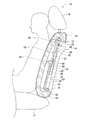
本発明の実施例の車両用シート10を図1に示す。車両用シート10は、運転席であり、運転者の臀部を支持するシートクッション12と、運転者の背部を支持するシートバック14と、シートバック14の上端に設けられて運転者の頭部を支持するヘッドレスト16とによって構成されている。
<Vehicle seat structure>
FIG. 1 shows a
シートバック14は、シートバック14の骨格となるバックフレーム20と、そのバックフレーム20を構成するアッパフレーム部22とロアフレーム部24との間に配設された弾性支持部材26と、その弾性支持部材26の前方側に配設された発泡ウレタン製のバックパッド28と、バックパッド28の表面を覆うバックカバー30と、シートバック14の背面側を覆うバックボード31とによって構成されている。
The
弾性支持部材26は、バックフレーム20のアッパフレーム部22とロアフレーム部24とに跨って架設された複数の支持ワイヤ32と、それら複数の支持ワイヤ32の前方側の下方に固定された平板状の前方側支持板34と、複数の支持ワイヤ32の後方側の上下方向における略中央に固定された平板状の後方側支持板36とによって構成されている。
The
前方側支持板34とシートバック14との間には、エアバック38が配設されている。エアバック38は、樹脂,ゴム等の機密性を有する材料によって袋状に形成されており、容量が変化する容器である。また、後方側支持板36の後方側の面の下方には、ポンプ50が固定され、後方側支持板36の後方側の面の上方には、エアタンク52が固定されている。なお、エアタンク52は、容量が変化しない容器である。そして、ポンプ50とエアタンク52とは、第1連通路54によって連通されている。また、第1連通路54とエアバック38とは、第2連通路56によって連通されている。なお、第1連通路54と第2連通路56との連通箇所には、第1電磁弁58が配設されている。第1電磁弁58は、ポンプ50とエアバック38との連通を許容した状態と、ポンプ50とエアタンク52との連通を許容した状態と、ポンプ50とエアバック38との連通及びポンプ50とエアタンク52との連通を禁止した状態とで切り替えられる切替弁である。
An
また、シートバック14の上部には、噴出口60が形成されている。噴出口60は、シートバック14のバックパッド28およびバックカバー30を概して前後方向に貫通しており、シートバック14の着座者側の面と、シートバック14の内部とに開口している。そして、噴出口60は、シートバック14の着座者側の面において、車両用シート10への着座者の頸部に向かって開口している。なお、着座者の頸部とは、着座者の頭部と胴体とを繋ぐ部分であり、着座者の首回り及び、肩回りを含む概念である。つまり、着座者の肩のラインと、そのラインより上方の部分とを含む概念である。また、車両用シート10への着座者は、頭部の後方をヘッドレスト16に支持され、背部をシートバック14に支持された状態で着座し、頸部の後方は、前方に向かってくびれている。そして、噴出口60は、その頸部に向かって開口している。このため、車両用シート10への着座者によって、噴出口60は塞がれない。つまり、噴出口60は、車両用シート10への着座者によって塞がれない位置に形成されている。
A
また、噴出口60のシートバック14の内部への開口と、エアタンク52とは、第3連通路62によって連通されている。その第3連通路62には、第2電磁弁66が配設されている。なお、第2電磁弁66は、エアタンク52と噴出口60との連通を許容した状態と、エアタンク52と噴出口60との連通を禁止した状態とで切り替えられる開閉弁である。
Further, the opening of the
また、バックフレーム20のアッパフレーム部22の近傍には、供給装置68が配設されている。供給装置68は、少量の水を供給するための装置であり、第4連通路70を介して、第3連通路62の噴出口60と第2電磁弁66との間に接続されている。なお、供給装置68により供給される水には、ミント等の眠気を覚醒させるための香りがつけられている。また、第4連通路70には、第3電磁弁72が配設されている。第3電磁弁72は、供給装置68と第3連通路62との連通を許容する状態と、供給装置68と第3連通路62との連通を禁止する状態とで切り替えられる開閉弁である。
Further, a
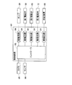
また、車両用シート10が配設される車両は、図2に示す制御装置80を備えている。制御装置80は、コントローラ82と、複数の駆動回路84とを有している。複数の駆動回路84は、ポンプ50、第1電磁弁58、第2電磁弁66、第3電磁弁72、供給装置68に接続されている。コントローラ82は、CPU,ROM,RAM等を備え、コンピュータを主体とするものであり、複数の駆動回路84に接続されている。これにより、ポンプ50、第1電磁弁58、第2電磁弁66、第3電磁弁72、供給装置68の作動が、コントローラ82によって制御される。
The vehicle on which the
さらに、車両用シート10が配設される車両は、車両用シート10への着座者、つまり、運転者の顔を撮像するカメラ86と、ステアリングに配設されるセンサ88とを備えている。カメラ86は、制御装置80のコントローラ82に接続されており、カメラ86により撮像された撮像データがコントローラ82に入力される。また、センサ88は、ステアリングを把持する運転者の脈拍を検出するものであり、コントローラ82に接続されている。これにより、センサ88による検出値が、コントローラ82に入力される。
Further, the vehicle on which the
<車両用シートの機能>
上記構造の車両用シート10は、ランバーサポート機能を有するとともに、そのランバーサポート機能で用いられるポンプを利用して、運転者の眠気を覚醒させることが可能である。詳しくは、ランバーサポート機能を操作するための操作部(図示省略)が操作されると、操作信号がコントローラ82に入力される。この際、第1電磁弁58の作動が、コントローラ82により制御され、ポンプ50とエアバック38との連通が許容された状態とされる。そして、ポンプ50の作動が制御され、エアバック38に規定の圧力まで、空気が送出される。これにより、エアバック38が膨張し、シートバック14の着座者の腰部を支持する部分の形状が変化することで、着座者の腰部がシートバック14によって適切に支持される。なお、エアバック38に規定の圧力まで空気が送出された後に、第1電磁弁58の作動が制御され、ポンプ50とエアバック38との連通が禁止されるとともに、ポンプ50とエアタンク52との連通も禁止された状態とされる。
<Functions of vehicle seat>
The
また、車両用シート10が配設される車両では、イグニッションがONにされると、第1電磁弁58の作動がコントローラ82により制御され、ポンプ50とエアタンク52との連通が許容された状態とされる。そして、ポンプ50の作動が制御され、エアタンク52に規定の圧力まで、空気が送出される。なお、第2電磁弁66および、第3電磁弁72は、通常、閉状態とされている。つまり、第2電磁弁66は、エアタンク52と噴出口60との連通を禁止した状態とされ、第3電磁弁72は、供給装置68と第3連通路62との連通を禁止した状態とされている。これにより、エアタンク52には、空気が圧縮された状態で貯蔵される。なお、エアタンク52に規定の圧力まで空気が送出された後に、第1電磁弁58の作動が制御され、ポンプ50とエアバック38との連通が禁止されるとともに、ポンプ50とエアタンク52との連通も禁止された状態とされる。
Further, in the vehicle in which the
また、車両では、イグニッションがONとされている間中、運転者の眠気の状態が監視されている。詳しくは、運転者の顔が、カメラ86により撮像されており、その撮像データは、コントローラ82に入力される。また、センサ88によって運転者の脈拍が検出されており、検出された運転者の脈拍がコントローラ82に入力される。そして、コントローラ82では、所定のアルゴリズムに従って、撮像データに基づく運転者の表情,センサ88による運転者の脈拍等から、運転者の眠気の状態が数値化され、演算される。また、運転者に眠気が高いと想定される状態、つまり、運転者が居眠りをしている状態、若しくは、居眠りする虞がある状態が数値化されており、設定範囲として設定されている。そして、演算された運転者の眠気の状態が設定範囲になった場合に、噴出信号が出力される。なお、コントローラ82で用いられるアルゴリズムは、周知の技術であるため、詳しい説明を省略する。
Further, in the vehicle, the state of sleepiness of the driver is monitored while the ignition is turned on. Specifically, the driver's face is captured by the
噴出信号が出力されると、まず、第3電磁弁72の作動が、コントローラ82により制御され、供給装置68と第3連通路62との連通が、極短い時間だけ、許容された状態とされる。また、供給装置68と第3連通路62との連通が許容された状態において、供給装置68の作動が制御され、供給装置68によって少量の水が供給される。これにより、第3連通路62に供給装置68から、少量の水が供給される。なお、第3連通路62に水が供給された後には、第3電磁弁72は、供給装置68と第3連通路62との連通が禁止された状態とされる。
When the ejection signal is output, first, the operation of the third
次に、第3連通路62に水が供給されると、第2電磁弁66の作動が、コントローラ82により制御され、エアタンク52と噴出口60との連通が許容された状態とされる。これにより、エアタンク52に圧縮された状態で貯蔵されている空気が、第3連通路62を介して、噴出口60から運転者の頸部に向かって噴出される。この際、第3連通路62に供給された少量の水は、圧縮された空気の流れによって水滴となり、空気と共に、噴出口60から運転者の頸部に向かって噴出される。
Next, when water is supplied to the
これにより、眠気の状態が高いと推定される運転者に向かって、空気が勢いよく噴出されるため、運転者に注意喚起を促し、運転者の眠気を効果的に覚醒させることが可能となる。また、空気だけでなく、水滴も運転者に噴出されるため、運転者の覚醒効果を高くすることが可能となる。さらに言えば、運転者に噴出される水滴には、ミント等の覚醒効果の高い香りがつけられているため、運転者の覚醒効果を更に高くすることが可能となる。また、空気等が噴出される運転者の頸部は、通常、露出している。つまり、衣類などを介することなく、直接的に、運転者の皮膚に空気等が噴出されるため、運転者の覚醒効果を非常に高くすることが可能となる。 As a result, air is ejected vigorously toward the driver who is estimated to have a high sleepiness state, so that the driver can be alerted and the driver's sleepiness can be effectively awakened. . Moreover, since not only air but also water droplets are ejected to the driver, the driver's awakening effect can be enhanced. Furthermore, since the water droplets ejected by the driver are given a scent having a high arousal effect such as mint, the awakening effect of the driver can be further enhanced. In addition, the neck of the driver from which air or the like is ejected is usually exposed. That is, air or the like is directly ejected to the driver's skin without going through clothing or the like, so that the driver's arousal effect can be made extremely high.
また、車両用シート10では、エアタンク52に空気を貯蔵するための駆動源として、ランバーサポート機能で用いられるポンプ50が利用されている。つまり、ランバーサポート機能の駆動源と、運転者を覚醒させるための機能の駆動源とが共有されている。これにより、運転者を覚醒させるための機能に要するコストを抑えることが可能となる。
In the
<制御プログラム>
上述したランバーサポート機能の実行および、運転者を覚醒させるための処理の実行は、コントローラ82において制御プログラムが実行されることによって行われる。以下に、図3及び図4を用いて、コントローラ82において制御プログラムが実行される際のフローを説明する。
<Control program>
The execution of the above-described lumbar support function and the execution of the process for awakening the driver are performed by executing a control program in the
制御プログラムは、図3に示すように、イグニッションがONにされると実行される。制御プログラムでは、まず、ポンプ50が作動され、エアタンク52に規定の圧力まで空気が送出される(S100)。この際、エアタンク52に空気が送出されている間は、第1電磁弁58が、ポンプ50とエアタンク52との連通が許容された状態とされ、エアタンク52への空気の送出が完了すると、第1電磁弁58が、ポンプ50とエアタンク52との連通および、ポンプ50とエアバック38との連通が禁止された状態とされる。
As shown in FIG. 3, the control program is executed when the ignition is turned on. In the control program, first, the
次に、噴出信号が出力されたか否かが、コントローラ82によって判断される(S102)。そして、噴出信号が出力されていない場合(S102:NO)には、S102の処理が繰り返される。一方、噴出信号が出力された場合(S102:YES)には、第3電磁弁72が、供給装置68と第3連通路62との連通を許容した状態とされ、第3連通路62に少量の水が供給される(S104)。なお、第3連通路62への水の供給が完了すると、第3電磁弁72が、供給装置68と第3連通路62との連通が禁止された状態とされる。
Next, it is judged by the
そして、第2電磁弁66が、エアタンク52と噴出口60との連通を許容した状態とされる(S106)。これにより、噴出口60から運転者の頸部に向かって、空気と水滴とが噴出される。なお、噴出口60からの空気等の噴出が完了すると、第2電磁弁66が、エアタンク52と噴出口60との連通が禁止された状態とされる。そして、S100に戻る。
Then, the second
また、制御プログラムでは、コントローラ82に操作信号が入力されると、図3に示すフローチャートに従った処理が停止し、図4に示す割込処理が実行される。この割込処理では、第1電磁弁58が、ポンプ50とエアバック38との連通を許容した状態とされ、ポンプ50が作動され、エアバック38に規定の圧力まで空気が送出される(S200)。なお、エアバック38への空気の送出が完了すると、第1電磁弁58が、ポンプ50とエアタンク52との連通および、ポンプ50とエアバック38との連通が禁止された状態とされる。そして、割込処理が終了し、図3に示すフローチャートに従った処理が再開される。
In the control program, when an operation signal is input to the
ちなみに、上記実施例において、車両用シート10は、乗物用シートの一例である。シートバック14は、シートバックの一例である。バックカバー30は、表皮の一例である。エアバック38は、気体袋の一例である。ポンプ50は、ポンプの一例である。エアタンク52は、貯蔵部の一例である。噴出口60は、噴出口の一例である。第3連通路62は、連通路の一例である。第2電磁弁66は、開閉弁の一例である。
Incidentally, in the above-described embodiment, the
なお、本発明は、上記実施例に限定されるものではなく、当業者の知識に基づいて種々の変更、改良を施した種々の態様で実施することができる。具体的には、例えば、上記実施例では、エアバック38がランバーサポート機能に用いられているが、着座者の側部を支持するためのサイドサポート機能、着座者をマッサージするためのマッサージ機能として、エアバックを用いることが可能である。
In addition, this invention is not limited to the said Example, It can implement in the various aspect which gave various change and improvement based on the knowledge of those skilled in the art. Specifically, for example, in the above embodiment, the
また、上記実施例では、エアタンク52に空気を送出するための駆動源として、ランバーサポート機能に用いられるポンプ50が採用されているが、エアタンク52に空気を送出するため専用のポンプを採用することが可能である。このような場合には、ランバーサポート機能等の無い車両用シートに、本発明を適用することが可能となる。
Moreover, in the said Example, although the
また、上記実施例では、運転者の眠気の状態が高いと想定される場合に、噴出口60から空気等が噴出されるが、他の種々の条件が成立した場合に、噴出口60から空気等を噴出させてもよい。具体的には、例えば、前方の車両との間隔が所定の距離より短くなった場合、走行中の車両が道路の車線からはみ出た場合等に、噴出口60から空気等を噴出させてもよい。
In the above embodiment, air or the like is ejected from the
また、上記実施例では、圧縮された空気を貯蔵する貯蔵部として、エアタンク52、つまり、容量の変化しない容器が採用されているが、容量の変化するエアバック等を採用することが可能である。
Moreover, in the said Example, although the
また、上記実施例では、着座者の頸部に空気等が噴出されているが、着座者の頭部に空気等を噴出させてもよい。また、噴出口60を1カ所だけでなく、複数形成してもよい。
Moreover, in the said Example, although air etc. are ejected to the seated person's neck, air etc. may be ejected to a seated person's head. Moreover, you may form not only one
また、上記実施例では、噴出口60がシートバック14に形成されているが、シートクッション12、ヘッドレスト16等に噴出口60を形成してもよい。
Moreover, in the said Example, although the
また、上記実施例では、本発明が車両用シート10に適用されているが、他の乗物、例えば、飛行機,船等の種々の乗物用のシートに本発明を適用することが可能である。
Moreover, in the said Example, although this invention is applied to the
10:車両用シート(乗物用シート)
14:シートバック
30:バックカバー(表皮)
38:エアバック(気体袋)
50:ポンプ
52:エアタンク(貯蔵部)
60:噴出口
62:第3連通路(連通路)
66:第2電磁弁(開閉弁)
10: Vehicle seat (vehicle seat)
14: Seat back 30: Back cover (skin)
38: Airbag
50: Pump 52: Air tank (storage part)
60: Spout 62: Third communication path (communication path)
66: Second solenoid valve (open / close valve)
Claims (5)
前記ポンプから送出された気体を圧縮させた状態で貯蔵する貯蔵部と、
前記貯蔵部に貯蔵された気体を着座者に向かって噴出する噴出口と、
前記貯蔵部と前記噴出口とを連通する連通路に配設される開閉弁と
を備え、
所定の条件が成立した場合に、前記開閉弁が開放され、前記噴出口から着座者に向かって気体が噴出されることを特徴とする乗物用シート。 A pump for delivering gas;
A storage section for storing the gas sent from the pump in a compressed state;
A spout for ejecting the gas stored in the storage section toward the seated person,
An on-off valve disposed in a communication path that connects the storage unit and the jet port;
The vehicle seat, wherein when a predetermined condition is satisfied, the on-off valve is opened and gas is ejected from the ejection port toward a seated person.
前記乗物用シートの内部に配設された気体袋を備え、
前記ポンプから前記気体袋に気体が送出されることで、前記乗物用シートの形状が変化することを特徴とする請求項1に記載の乗物用シート。 The vehicle seat is
A gas bag disposed inside the vehicle seat;
The vehicle seat according to claim 1, wherein the shape of the vehicle seat changes when gas is sent from the pump to the gas bag.
着座者の頭部と頸部との少なくとも一方に向かって気体を噴出することを特徴とする請求項1または請求項2に記載の乗物用シート。 The spout is
The vehicle seat according to claim 1, wherein gas is ejected toward at least one of a head and a neck of the seated person.
シートバックの上部に形成されることを特徴とする請求項1乃至請求項3のいずれか1項に記載の乗物用シート。 The spout is
The vehicle seat according to any one of claims 1 to 3, wherein the vehicle seat is formed on an upper portion of a seat back.
前記乗物用シートの表皮に貫通していることを特徴とする請求項1乃至請求項4のいずれか1項に記載の乗物用シート。 The spout is
The vehicle seat according to any one of claims 1 to 4, wherein the vehicle seat penetrates the skin of the vehicle seat.
Priority Applications (1)
| Application Number | Priority Date | Filing Date | Title |
|---|---|---|---|
| JP2016097624A JP2017206041A (en) | 2016-05-16 | 2016-05-16 | Vehicle seat |
Applications Claiming Priority (1)
| Application Number | Priority Date | Filing Date | Title |
|---|---|---|---|
| JP2016097624A JP2017206041A (en) | 2016-05-16 | 2016-05-16 | Vehicle seat |
Publications (1)
| Publication Number | Publication Date |
|---|---|
| JP2017206041A true JP2017206041A (en) | 2017-11-24 |
Family
ID=60415208
Family Applications (1)
| Application Number | Title | Priority Date | Filing Date |
|---|---|---|---|
| JP2016097624A Pending JP2017206041A (en) | 2016-05-16 | 2016-05-16 | Vehicle seat |
Country Status (1)
| Country | Link |
|---|---|
| JP (1) | JP2017206041A (en) |
Cited By (1)
| Publication number | Priority date | Publication date | Assignee | Title |
|---|---|---|---|---|
| US11521773B2 (en) | 2018-04-27 | 2022-12-06 | Conti Temic Microelectronic Gmbh | Pneumatic solenoid valve |
Citations (9)
| Publication number | Priority date | Publication date | Assignee | Title |
|---|---|---|---|---|
| JPS54109249U (en) * | 1978-01-11 | 1979-08-01 | ||
| JPS5698054U (en) * | 1979-12-27 | 1981-08-03 | ||
| JPS58116322A (en) * | 1981-12-29 | 1983-07-11 | 日産自動車株式会社 | Seat for automobile |
| JPS61253239A (en) * | 1985-05-07 | 1986-11-11 | Nissan Motor Co Ltd | Safety device for vehicle |
| JPH0199266U (en) * | 1987-12-25 | 1989-07-03 | ||
| DE3804848A1 (en) * | 1988-02-17 | 1989-08-31 | Steinbrueck Peter | Control device for inflatable inlays |
| JP2007215695A (en) * | 2006-02-15 | 2007-08-30 | Toyota Motor Corp | Vehicle seat |
| JP2016124364A (en) * | 2014-12-26 | 2016-07-11 | 本田技研工業株式会社 | Awakener |
| JP2016168933A (en) * | 2015-03-13 | 2016-09-23 | いすゞ自動車株式会社 | Doze prevention system of vehicle |
-
2016
- 2016-05-16 JP JP2016097624A patent/JP2017206041A/en active Pending
Patent Citations (9)
| Publication number | Priority date | Publication date | Assignee | Title |
|---|---|---|---|---|
| JPS54109249U (en) * | 1978-01-11 | 1979-08-01 | ||
| JPS5698054U (en) * | 1979-12-27 | 1981-08-03 | ||
| JPS58116322A (en) * | 1981-12-29 | 1983-07-11 | 日産自動車株式会社 | Seat for automobile |
| JPS61253239A (en) * | 1985-05-07 | 1986-11-11 | Nissan Motor Co Ltd | Safety device for vehicle |
| JPH0199266U (en) * | 1987-12-25 | 1989-07-03 | ||
| DE3804848A1 (en) * | 1988-02-17 | 1989-08-31 | Steinbrueck Peter | Control device for inflatable inlays |
| JP2007215695A (en) * | 2006-02-15 | 2007-08-30 | Toyota Motor Corp | Vehicle seat |
| JP2016124364A (en) * | 2014-12-26 | 2016-07-11 | 本田技研工業株式会社 | Awakener |
| JP2016168933A (en) * | 2015-03-13 | 2016-09-23 | いすゞ自動車株式会社 | Doze prevention system of vehicle |
Cited By (1)
| Publication number | Priority date | Publication date | Assignee | Title |
|---|---|---|---|---|
| US11521773B2 (en) | 2018-04-27 | 2022-12-06 | Conti Temic Microelectronic Gmbh | Pneumatic solenoid valve |
Similar Documents
| Publication | Publication Date | Title |
|---|---|---|
| US20170028163A1 (en) | Vehicle seat | |
| US9517744B2 (en) | Vehicle occupant protection device | |
| KR101063385B1 (en) | Intelligent vehicle seat support system | |
| KR20200043123A (en) | Frontal airbag for vehicle and airbag deployment system using same | |
| JP2019084894A (en) | Vehicle seat and seat cushion airbag | |
| JP2016078768A (en) | Vehicular far side airbag device | |
| JP4332191B2 (en) | Sheet structure | |
| JP2017206041A (en) | Vehicle seat | |
| JP2018095015A (en) | Vehicle seat | |
| JP6365589B2 (en) | Vehicle occupant protection device | |
| CN110949224B (en) | Automobile seat and control method thereof | |
| JP2023129647A (en) | vehicle seat | |
| JP2020162907A (en) | Vehicle seat | |
| JP2023099652A (en) | seat system | |
| JP2018070075A (en) | Vehicle seat | |
| JP2020090259A (en) | Air bag device | |
| JP2019123278A (en) | Seat cushion airbag device | |
| CN206336170U (en) | A kind of air bag SAHR structure | |
| JP7235565B2 (en) | vehicle seat | |
| JP2019031186A (en) | Seat with warning function | |
| JP7211870B2 (en) | vehicle seat | |
| JPH11342775A (en) | Seating posture keepable vehicular seat | |
| CN219969493U (en) | Vehicle seat and vehicle | |
| JP4487665B2 (en) | Vehicle seat belt device | |
| JP2022041856A (en) | In-vehicle system |
Legal Events
| Date | Code | Title | Description |
|---|---|---|---|
| A621 | Written request for application examination |
Free format text: JAPANESE INTERMEDIATE CODE: A621 Effective date: 20181127 |
|
| A977 | Report on retrieval |
Free format text: JAPANESE INTERMEDIATE CODE: A971007 Effective date: 20190905 |
|
| A131 | Notification of reasons for refusal |
Free format text: JAPANESE INTERMEDIATE CODE: A131 Effective date: 20190910 |
|
| A02 | Decision of refusal |
Free format text: JAPANESE INTERMEDIATE CODE: A02 Effective date: 20200303 |