JP2017205073A - Water supply system - Google Patents
Water supply system Download PDFInfo
- Publication number
- JP2017205073A JP2017205073A JP2016100703A JP2016100703A JP2017205073A JP 2017205073 A JP2017205073 A JP 2017205073A JP 2016100703 A JP2016100703 A JP 2016100703A JP 2016100703 A JP2016100703 A JP 2016100703A JP 2017205073 A JP2017205073 A JP 2017205073A
- Authority
- JP
- Japan
- Prior art keywords
- water
- intake hose
- water supply
- source pond
- float
- Prior art date
- Legal status (The legal status is an assumption and is not a legal conclusion. Google has not performed a legal analysis and makes no representation as to the accuracy of the status listed.)
- Granted
Links
Images


Abstract
Description
この発明は、給水システムに関し、特にたとえば、堤体で堰き止められた水源池の水を、堤体を挟んで水源池とは反対側にある圃場に供給する給水システム、給水システムに関する。 The present invention relates to a water supply system, and more particularly to a water supply system and a water supply system that supply water from a water source pond blocked by a bank body to a field on the opposite side of the water source pond across the bank body.
この発明の背景となる従来の給水システムの一例が特許文献1に開示されている。この給水システムでは、溜め池のような水源に浮かべた取水フロートから取水ホースを介して、給水管を構成するサイホン管部へ水を取込む。 An example of a conventional water supply system as the background of the present invention is disclosed in Patent Document 1. In this water supply system, water is taken into a siphon pipe portion constituting the water supply pipe through a water intake hose from a water intake float floated on a water source such as a reservoir.
この給水システムでは、取水ホースが取水フロートの近くで水面から出てしまい、給水管への水の送り込みができなくなる場合がある。つまり、取水ホースが柔軟であるため、ホース内に空気が滞留すると滞留した箇所が浮上して水面より飛び出してしまい、取水口からの水の供給を遮断し、取水できなくなる。 In this water supply system, the water intake hose may come out of the water surface near the water intake float, making it impossible to feed water into the water supply pipe. In other words, since the water intake hose is flexible, when the air stays in the hose, the stayed part floats up and jumps out of the water surface, shuts off the water supply from the water intake and cannot take in water.
取水ホースが浮上してしまった場合には、浮上した箇所を水面下に押し込むか、取水フロートを吊上げて、空気を取水口より排出し、取水ホースを沈めなければならない。浮上した取水ホースを水面下に押し込むにはボート2隻、作業者4名以上またはダイバー2名以上で行う必要がある。取水フロートを吊上げるにはユニック車等のクレーン車を準備して取水フロートを慎重に水面から上に吊上げる必要がある。 If the water intake hose has surfaced, it must be pushed down below the surface of the water, or the water intake float must be lifted to discharge the air from the water intake and sink the water intake hose. In order to push the surfacing intake hose below the surface of the water, it is necessary to carry out by two boats, four workers or more or two divers. In order to lift the intake float, it is necessary to prepare a crane vehicle such as a UNIC vehicle and carefully lift the intake float from the water surface.
どちらにしても、このような取水ホースの浮上事故が生じたときには、多くの人員、設備、時間を要することになる。 In any case, when such a water intake hose levitation accident occurs, it takes a lot of personnel, equipment, and time.
それゆえに、この発明の主たる目的は、新規な、給水システムを提供することである。 Therefore, the main object of the present invention is to provide a novel water supply system.
この発明の他の目的は、取水ホースの浮き上がりを可及的防止できる、給水システムを提供することである。 Another object of the present invention is to provide a water supply system that can prevent the intake hose from floating as much as possible.
この発明は、上記の課題を解決するために、以下の構成を採用した。なお、括弧内の参照符号および捕捉説明などは、本発明の理解を助けるために後述する実施の形態との対応関係を示したものであって、この発明を何ら限定するものではない。 The present invention employs the following configuration in order to solve the above problems. Note that the reference numerals in parentheses and the description of capture indicate correspondence with the embodiments described later to help understanding of the present invention, and do not limit the present invention.
第1の発明は、堤体で堰き止められた水源池の水を、堤体を挟んで水源池とは反対側にある圃場に供給する給水システムであって、水源池に浮かべられ、取水部から水源池の水を取り込むフロート、フロートに先端が連結されてフロート内に取り込まれた水が送り込まれる取水ホース、および水源池内で取水ホースの基端に連結され、取水ホースが取水した水を圃場に導く給水管路を備え、取水ホースはその中の空気を抜くために形成された空気抜き部を含む、給水システムである。 1st invention is a water supply system which supplies the water of the water source pond blocked by the bank body to the farm field on the opposite side to the water source pond across the bank body, floated on the water source pond, Float that takes water from the water source pond from the water, a water intake hose that is connected to the float and the water that is taken into the float is fed into the water source pond, and a water intake hose that is connected to the base end of the water intake hose in the water source pond. The water intake hose is a water supply system that includes an air vent formed to vent air therein.
第1の発明では、給水システム(10:実施例において対応する部分を例示する参照符号。以下同様。)は、溜め池のような水源地(14)に貯留している用水を、水源地を堰き止める堤体(12)を挟んで反対側にある圃場に供給する。水源地の水面には取水フロート(24)が係留ロープ(28、30)で係留された状態で浮かべられる。取水フロートは水源地の水を取込み、それを、取水フロートに連結された取水ホース(22)に送る。取水ホースに連結された給水管路(18、50)が、取水ホースからの水を圃場に導く。取水ホースのたとえば上流側には、取水ホース内の空気を、たとえば大気中に放出するなどして抜くための空気抜き部(64)が形成される。取水ホースが水源地の水面(66)から完全に浮き上がってしまっているとき、その部分に滞留している空気は、空気抜き部を通って大気中に放出される。したがって、取水ホースが沈み、やがて取水ホースの内部での水面が水源地の水面と同じレベルとなり、取水ホース内での通水が可能な状態となる
第1の発明によれば、取水ホースがその中に滞留した空気によって水源地の水面から浮き上がったときでも、空気抜き部から空気を放出して、取水ホースを通水可能な状態にすることができる。したがって、従来であれば必要であった多くの人員、設備、時間が節約できる。
In the first invention, the water supply system (10: reference numerals exemplifying corresponding parts in the embodiment; the same applies hereinafter) is used to store the water stored in the water source (14) such as a reservoir, and the water source Supply to the field on the opposite side across the dam body (12) to be dammed. A water intake float (24) is floated on the surface of the water source while being moored by mooring ropes (28, 30). The intake float takes water from the source and sends it to the intake hose (22) connected to the intake float. Water supply pipes (18, 50) connected to the intake hose guide water from the intake hose to the field. For example, on the upstream side of the intake hose, an air vent (64) is formed for extracting the air in the intake hose by, for example, releasing it into the atmosphere. When the water intake hose is completely lifted from the water surface (66) of the water source, the air staying in that portion is released into the atmosphere through the air vent. Therefore, the water intake hose sinks, and eventually the water surface inside the water intake hose becomes the same level as the water surface of the water source, and the water can be passed through the water intake hose. Even when the air stays inside and rises from the water surface of the water source, the air can be discharged from the air vent and the intake hose can be passed through. Therefore, it is possible to save many personnel, equipment, and time that were necessary in the past.
第2の発明は、第1の発明に従属し、空気抜き部は、取水ホースの先端と基端との間の中間より先端側に形成される、給水システムである。 2nd invention is a water supply system which depends on 1st invention, and an air vent part is formed in the front end side rather than the middle between the front-end | tip and base end of a water intake hose.
第2の発明では、空気抜き部は、取水ホースの中間より上流側(先端側)に形成される。たとえば、取水ホースが10mの長さのものであるとすれば、その上流側の半分(5m)に形成される。取水ホースが浮上して取水ができなくなるのは、多くは取水ホースの上流側が浮上してしまった場合であるからである。 In 2nd invention, an air vent part is formed in the upstream (front end side) from the middle of a water intake hose. For example, if the intake hose has a length of 10 m, it is formed in the upstream half (5 m). The reason why the water intake hose floats and cannot be taken is because the upstream side of the water intake hose has floated.
第2の発明では、取水ホースの浮上による取水不能状態を可及的速やかに解消することができる。 In the second aspect of the invention, it is possible to eliminate as soon as possible the inability to take water due to the floating of the water intake hose.
第3の発明は、第1または第2の発明に従属し、空気抜き部は、取水ホースに、取水ホースの管軸方向に間隔を隔てて形成された複数の空気抜き孔を含む、給水システムである。 3rd invention is a water supply system which depends on 1st or 2nd invention, and an air vent part contains the several air vent hole formed in the water intake hose at intervals in the pipe-axis direction of the water intake hose. .
第3の発明では、空気抜き部が、取水ホースの管軸方向に間隔を隔てて形成された複数の空気抜き孔(64)を含む。空気抜き孔を管軸方向のある程度の範囲にわたって分散して複数の空気抜き孔を形成したので、取水ホース内の広い範囲から空気を抜くことができる。 In 3rd invention, an air vent part contains the several air vent hole (64) formed at intervals in the pipe-axis direction of the water intake hose. Since the plurality of air vent holes are formed by dispersing the air vent holes over a certain range in the tube axis direction, air can be extracted from a wide range in the water intake hose.
第3の発明によれば、複数の空気抜き孔の1つからでも空気を放出することができるので、取水ホース内の空気を効率的に抜くことができる。 According to the third aspect of the invention, air can be released even from one of the plurality of air vent holes, so that the air in the water intake hose can be efficiently extracted.
第4の発明は、第3の発明に従属し、取水ホースの外面に設けられて、複数の空気抜き孔の対応するものを外面から塞ぐ複数のシートをさらに備える、給水システムである。 A fourth invention is a water supply system according to the third invention, further comprising a plurality of sheets provided on the outer surface of the water intake hose and blocking corresponding ones of the plurality of air vent holes from the outer surface.
第4の発明では、シートが空気抜き孔を取水ホース外面から覆うので、取水ホース内の空気は空気抜き孔から排気されるが、水源池からの逆流をシートが弁として働き遮断できる。 In the fourth aspect of the invention, since the sheet covers the air vent hole from the outer surface of the water hose, the air in the water intake hose is exhausted from the air vent hole, but the sheet can act as a valve to block the reverse flow from the water source pond.
第4の発明によれば、シートによって、水源池から取水ホース内に逆流するのを防止することができる。 According to 4th invention, it can prevent backflow in a water intake hose from a water source pond with a sheet | seat.
第5の発明は、第1ないし第4のいずれかの発明に従属し、給水管路は堤体下を通る給水管路および堤体の外で給水管路に連結される接続管部を含み、水は接続管部に設けられた仕切弁を経て圃場に給水され、さらに仕切弁より上流側の給水管路に形成された加圧注水部を備える、給水システムである。 A fifth invention is dependent on any one of the first to fourth inventions, and the water supply pipe includes a water supply pipe passing under the dam body and a connecting pipe portion connected to the water supply pipe outside the dam body. Water is supplied to the field through a gate valve provided in the connection pipe part, and further includes a pressurized water injection part formed in the water supply pipe upstream of the gate valve.
第5の発明では、給水管路は堤体(12)下を通って堤体外にまで延びる給水管路(18)とこの給水管路と放水管路(52)を接続する接続管路(50)を含み、水は接続管路に設けられた仕切弁(61)を経て放水管路から圃場に給水される。加圧注水部(70、72)が仕切弁より上流側の接続管路に形成され、この加圧注水部から水を加圧注入すると、取水ホース内の滞留空気が上流側へ移動して、空気抜き抜き部(64)から放出できるようになる。 In the fifth aspect of the invention, the water supply pipe is connected to the water supply pipe (18) extending below the bank body (12) to the outside of the bank body and the connection pipe line (50) connecting the water supply pipe and the water discharge pipe (52). The water is supplied to the field from the water discharge pipe through the gate valve (61) provided in the connection pipe. When the pressurized water injection part (70, 72) is formed in the connecting pipe line upstream from the gate valve, when water is injected under pressure from this pressurized water injection part, the staying air in the intake hose moves upstream, The air can be discharged from the air vent (64).
第5の発明によれば、加圧注入部から水を加圧注入すると取水ホース内の滞留空気が移動するので、空気抜き部からの空気抜きを確実に行うことができる。 According to the fifth aspect of the invention, when the water is pressurized and injected from the pressure injection part, the staying air in the water intake hose moves, so that the air can be reliably released from the air release part.
第6の発明は、堤体で堰き止められた水源池の水を、堤体を挟んで水源池とは反対側にある圃場に供給するために、水源池に浮かべられ、取水部から水源池の水を取り込むフロート、フロートに先端が連結されてフロート内に取り込まれた水が送り込まれる取水ホース、および水源池内で取水ホースの基端に連結され、取水ホースが取水した水を圃場に導く給水管路を備える給水システムにおいて、浮上した取水ホースを水源池の水面下に沈める方法であって、取水ホースに形成した空気抜き部から空気を放出することによって取水ホースを沈めるようにした、取水ホースを沈める方法である。 6th invention floats in a water source pond in order to supply the water of a water source pond blocked by a bank body to the field on the opposite side to a water source pond across the bank body, Float that takes in water, a water intake hose that has a tip connected to the float and that feeds water taken into the float, and a water supply that is connected to the proximal end of the water intake hose in the water source pond and leads the water taken by the water intake hose to the field In a water supply system having a pipe line, a method of sinking a floating intake hose below the surface of a water source pond, wherein the intake hose is submerged by releasing air from an air vent formed in the intake hose. It is a method of sinking.
第6の発明では、空気抜き部(64)の近傍で取水ホース(22)内に空気が滞留して、取水ホースが水源地(14)の水面(66)から完全に浮き上がってしまっているとき、その部分に滞留している空気は、空気抜き部を通って大気中に放出される。したがって、取水ホースが沈降し、やがて取水ホースの内部での水面が水源地の水面と同じレベルとなり、取水ホース内での通水が可能な状態となる。 In the sixth invention, when air stays in the intake hose (22) in the vicinity of the air vent (64) and the intake hose has completely lifted from the water surface (66) of the water source (14), The air staying in the part is released into the atmosphere through the air vent. Therefore, the water intake hose settles, and the water surface inside the water intake hose eventually becomes the same level as the water surface of the water source, so that water can pass through the water intake hose.
第6の発明でも、第1の発明と同様の効果が期待できる。 In the sixth invention, the same effect as in the first invention can be expected.
第7の発明は、第6の発明に従属し、給水管路の下流側から水を加圧注入することによって、取水ホース内の滞留空気を空気抜き部まで移動させる、取水ホースを沈める方法である。 A seventh invention is a method according to the sixth invention, in which the intake air in the intake hose is moved to the air vent by injecting water under pressure from the downstream side of the water supply pipe, and the intake hose is sunk. .
第7の発明では、給水システムの給水管路は、たとえば堤体(12)下を通って堤体外にまで延びる給水管路(18)とこの給水管路と放水管路(52)接続する接続管路(50)を含み、水は接続管路に設けられた仕切弁(61)を経て放水管路から圃場に給水される。加圧注水部(62、72)が仕切弁より上流側の接続管路に形成され、この加圧注水部から水を加圧注入すると、取水ホース内の滞留空気が上流側へ移動して、空気抜き抜き部(64)から放出できるようになる。 In the seventh invention, the water supply line of the water supply system is connected to, for example, a water supply line (18) extending below the dam body (12) to the outside of the dam body, and connecting the water supply line and the water discharge line (52). Water is supplied to the field from the water discharge pipe through the gate valve (61) provided in the connection pipe including the pipe (50). When the pressurized water injection part (62, 72) is formed in the connecting pipe line upstream from the gate valve and water is injected under pressure from this pressurized water injection part, the staying air in the intake hose moves upstream, The air can be discharged from the air vent (64).
第7の発明によれば、取水ホースを効率的に沈めることができる。 According to the seventh aspect, the water intake hose can be efficiently sunk.
第8の発明は、堤体で堰き止められた水源池の水を、堤体を挟んで水源池とは反対側にある圃場に供給するために、水源池に浮かべられ、取水部から水源池の水を取り込むフロート、フロートに先端が連結されてフロート内に取り込まれた水が送り込まれる取水ホース、および水源池内で取水ホースの基端に連結され、取水ホースが取水した水を圃場に導く給水管路を備え、給水管路は堤体下を通る給水管路および堤体の外で給水管路に連結される接続管部を含み、水は接続管部に設けられた仕切弁を経て圃場に給水される給水システムにおいて、浮上した取水ホースを水源池の水面下に沈める方法であって、仕切弁より上流側の接続管部において加圧注水することによって取水ホースを沈めるようにした、取水ホースを沈める方法である。 In the eighth invention, in order to supply the water from the water source pond blocked by the bank body to the farm field on the opposite side of the water source pond across the bank body, the water source pond is floated on the water source pond. Float that takes in water, a water intake hose that has a tip connected to the float and that feeds water taken into the float, and a water supply that is connected to the proximal end of the water intake hose in the water source pond and leads the water taken by the water intake hose to the field The water supply line includes a water supply line that passes under the dam body and a connection pipe part that is connected to the water supply line outside the dam body, and water is supplied to the field through a gate valve provided in the connection pipe part. In the water supply system, the intake hose that has floated is submerged under the surface of the water source pond, and the intake hose is submerged by pressurized water injection in the connecting pipe upstream of the gate valve. This is a method of sinking the hose.
第8の発明では、たとえば接続管路(50)に設けた加圧注水部(62、72)で取水ホース(22)の中の空気溜まりを上流側に押し上げて取水ホースの先端まで運ぶことができる。そうすると、空気は取水ホース、取水フロートを経て、大気中へ放出される。そのため、取水ホース内の空気量が減り、取水ホースが沈降して、やがて通水可能な状態になる。 In the eighth invention, for example, the pressurized water injection section (62, 72) provided in the connection pipe (50) pushes the air reservoir in the intake hose (22) upstream and carries it to the tip of the intake hose. it can. Then, air is discharged into the atmosphere through the intake hose and the intake float. Therefore, the amount of air in the water intake hose decreases, the water intake hose settles, and it becomes possible to pass water before long.
第8の発明によれば、取水ホースを効率的に沈めることができる。 According to the eighth invention, the water intake hose can be efficiently sunk.
この発明によれば、取水ホースに空気抜き部を設けたので、取水ホース内に滞留した空気が、そこから排出されるため、取水ホースの浮上を防止することができる。そのため、取水ホースが浮上して取水ができなくなるという事態を、多くの人員、設備、時間を要しないで、解消することができる。 According to this invention, since the air vent part is provided in the water intake hose, the air staying in the water intake hose is discharged therefrom, and therefore the water intake hose can be prevented from rising. Therefore, the situation that the water intake hose rises and water cannot be taken can be eliminated without requiring a lot of personnel, equipment, and time.
この発明の上述の目的、その他の目的、特徴および利点は、図面を参照して行う後述の実施例の詳細な説明から一層明らかとなろう。 The above object, other objects, features, and advantages of the present invention will become more apparent from the following detailed description of embodiments with reference to the drawings.
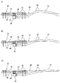
図1および図2を参照して、この発明の一実施例の取水システム10は、堤体12によって堰き止められた水源池14から、圃場(図示せず)へ給水するための設備である。具体的には、堤体12の地下に、たとえばヒューム管によって形成されている隧道16を利用して、水源池14からの水を圃場に設けられた放水ピット(図示せず)に放水(吐出)する。
Referring to FIGS. 1 and 2, a
なお、隧道16は、水源池14を設けるときに必ず堤体12内に作っておくものであり、この実施例では、このような既設の隧道16を利用するようにしているので、工事費を抑制できる。なお、隧道16を形成するヒューム管の呼び径は、一例として600‐800であるが、これに限定されるものではない。
In addition, when the
実施例の取水システム10では、隧道16内に、たとえばPE(ポリエチレン)管の突合せ接合(バット融着)によって給水管路18を敷設する。この給水管路18の呼び径は、一例として200‐250であるが、これに限定されるものではない。
In the
なお、給水管路18を隧道16内に敷設する方法は、詳しくは説明しないが、いわゆる「パイプインパイプ方式」を採用する。そのため、堤体12や隧道16の大規模な改修工事は必要なく、比較的安価に設置できる。
Although the method for laying the
なお、水源地を新しく作る場合には、給水管路18は隧道とは別に敷設するようにしてもよい。その場合、給水管路は、たとえば周囲をコンクリートで固めるなどして、堤体を遮水したり、土圧に耐えられる工夫がされている。
In addition, when making a water source new, you may make it construct the water
給水管路18の入り口側には、接続管路20を介して、取水ホース22が接続される。取水ホース22は、一例として軟質塩ビからなる柔軟な直管であり、その先端が取水フロート24に連結される。接続管路20は、水源池14の側の堤体12の基底部の近傍にたとえばコンクリートで形成される固定台26によって、水源池14の底部に固定的に係止される。ただし、取水ホース22は、蛇腹管のようなフレキシブル管で構成されてもよい。
A
なお、詳細は図示しないが、接続管路20に接続された給水管路18の入口端と、隧道16の上流コンクリート構造物との貫通部は、たとえばコンクリートによって封止される。同様に、給水管路18の出口端と、隧道16の下流コンクリート構造物との貫通部もたとえばコンクリートによって封止される。つまり、給水管路18は、隧道16内ではいわゆる「転がし配管」であり、両端のみがコンクリート構造物によって固定される。したがって、給水管路18は、PE管であることと相俟って、温度差による伸縮に容易に対応できる。
Although not shown in detail, a penetration portion between the inlet end of the
上述の取水フロート24は、比較的温度が高い表面水を取水するためのものであって、水位の変動に伴って取水ホース22が屈曲することにより上下動する。ただし、取水フロート24の必要以上の搖動を抑制するために、取水フロート24は、係留ロープ28および30によって、係留される。係留ロープ28の基端は、水源池14内に固定された架台32に支持された係留ポール34に係止され、係留ロープ30の基端は、堤体12上に固定された架台36に支持された支持具38に係止される。
The above-described
図3からよく分かるように、取水フロート24は、上下2つの部材からなり、上側のフロート部40は平面形状が矩形の大小2つの中空密封パイプからなり、この取水フロート24に浮力を付与する。フロート部40の下側には、平面形状がたとえば「十」の字に形成された取水部42が取り付けられている。この取水部42の各辺のそれぞれの両側に多数の取水口44が分散して形成されている。したがって、取水部42は各取水口44から取水して、その水を取水ホース22に送り込む。
As can be clearly understood from FIG. 3, the
詳しくいうと、取水ホース22の先端には矩形箱状の受水部46が取り付けられ、この受水部46が取水部42の中央に形成された送水部48に固着される。したがって、送水部48の底面に形成された送水口(図示せず)および受水部46の天面に形成された受水口(図示せず)が連通するように、受水部46と送水部48が接合され、取水部42が取水した水が、送水口、受水口を通して、取水ホース22に送り込まれる。
More specifically, a rectangular box-shaped
このようにして取水ホース22に取り込まれた水源地14の水は、隧道16内の給水管路18に入る。給水管路18は、接続管路50を経て、圃場(図示せず)に放水する放水管路52に接続さる。水は接続管路50を経て放水管路52に供給されるので、「給水管路」というとき、給水管路18および接続管路50の両方を指すことがあることに留意されたい。
Thus, the water in the
給水管路18に接続されている接続管路50には、詳細は図示しないが排気弁装置54が設けられる。この排気弁装置54は圃場側から侵入した空気を排出し、上流への空気の浮上を遮断する。その詳細は、本件出願人の出願に係る同時係属中の特願2016‐93670に詳しく説明されているので、ここではその記載を援用することによって詳細な説明は省略する。
Although not shown in detail in the
図1および図2では明瞭ではないので、ここでは、便宜上図8を参照して、排気弁装置54を簡単に説明する。排気弁装置54はタンク56を有し、そのタンク56の上端に、それぞれがフロート58の上下動によって開閉される2つの排気弁60が形成される。ただし、この実施例では、フロート58の上端に固着したゴムパッキンのような弁体と、この弁体がフロート58の上下動に応じて接離する弁座からなる。したがって、タンク56内に溜まっている水に空気が混じっていてその水位が低下すると、フロート58が下がり、排気弁60が開けられて、タンク56中の水から放出された空気が、排気弁60から大気中へ放出される。さらに、給水管路18すなわち接続管路50からの給水が減少しまたは途絶したときに、タンク56内の水位が流出側以下になると、タンク56からの水の流出が止まる。
Since it is not clear in FIG. 1 and FIG. 2, here, the
また、排気弁装置54のタンク56における接続管路50からの流入側が放水管路52への流出側に比べて低位にあるため、タンク56内水位が流出側以下になっても、流入側は未だタンク56内の水位より下にあるため、流入側が塞がれたトラップが形成される。したがって、空気が給水管路18を逆流することはない。
Further, since the inflow side from the
接続管路50の排気弁装置54のさらに少し上流側には、仕切弁61が設けられ、さらに上流には加圧注水部62が配置される。加圧注水部62は、接続管路50すなわち給水管路18内に水を注入するために利用されるものであるが、その作用は、取水ホース22の管頂に形成された空気抜き孔64(図3)の作用とともに、後述する。
A
なお、加圧注水部62は、たとえばフランジ継手で接続管路50内に介挿され、たとえば仕切弁または逆止弁を経た管端に、たとえば加圧ポンプ(図示せず)を連結して、接続管路50内に加圧注水する。
In addition, the pressurized
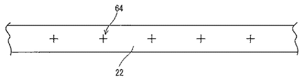
図3に示すように、取水ホース22の取水フロート24の近傍の管頂に、取水ホース22の管壁を貫通する複数の(実施例では5つの)空気抜き孔64を形成する。一例として、この実施例では、取水フロート24の長さ(図3における左右方向または長さ)が3.6mであり、送水部48がその中心であるので、送水部48を挟んで左右それぞれ1.8mである。そして、その取水フロート24の送水部48から2‐4mの範囲に0.5mの間隔を隔てて5つの空気抜き孔64を形成する。つまり、この実施例では、空気抜き孔64は、送水部48から2.0m、2.5m、3.0m、3.5mおよび4.0mの位置に形成される。
As shown in FIG. 3, a plurality of (five in the embodiment) air vent holes 64 penetrating the pipe wall of the
ただし、その孔64のサイズ(直径)は一例として1mm程度とした。この空気抜き孔64のサイズをあまり大きくすると、取水ホース22のその部分での強度の低下を招来する、空気抜き孔64の数を多くしすぎても同様の不都合が生じる。さそらに、空気抜き孔64の間隔を小さくしすぎて空気抜き孔64を密集させてしまうと、その密集部分での取水ホース22の強度低下が問題になるばかりでなく、空気抜き孔64から空気を抜くことができる、取水ホース22の軸方向長さが短くなり、広範囲の空気滞留に十分対処できないという懸念がある。そこで発明者は、実験を通して、上述のような仕様を決めた。ただし、これらの数値は一例であって、そのままこの発明を限定するものではないことは、もちろんである。
However, the size (diameter) of the
先に説明したように、取水ホース22が浮上して給水ができなくなるという問題があるが、現状の給水システムでは、水源地(溜め池)の水の貯留時に取水ホース22の浮上を防ぐために、予め取水ホース22および給水管路18内に用水を注入して空気の排出を行っているが、排気が十分に行われず、取水ホース22が浮上する事態が発生している。また、溜め池によっては池干しや、干ばつによる用水涸れが発生することがあり、この場合には取水ホース22および給水管路18への用水注水が行われず、溜め池への水の貯留が始まり、取水ホース22が浮上することもある。
As described above, there is a problem that the
現状の取水ホ-ス22では、取水フロート24の移動に追従できるように柔軟性を確保しているが、その中の滞留空気が取水ホース上流(池底から取水フロート24側)に移動する過程で、取水ホース22を浮上させ水面66上にホースの一部を押し曲げて浮かせてしまう。その状態が図4(A)に示される。
The
図4(A)の状態では、空気抜き孔64の近傍で空気が滞留して、取水ホース22が水源地の水面66から完全に浮き上がってしまっている。しかしながら、この実施例では、この浮き上がった取水ホース22の場所に、空気抜き孔64がある。そのため、浮き上がっている部分に滞留している空気は、1つ以上の空気抜き孔64を通って大気中に放出される。したがって、取水ホース22が図4(B)で示すように、やや沈下する。
In the state of FIG. 4A, air stays in the vicinity of the
その後、取水ホース22の空気抜き孔64から空気がさらに放出され、取水ホース22はさらに沈下する。そうすると、図4(C)に示すように、取水ホース22の内部での水面が水源地14の水面66と同じレベルとなり、取水ホース22内での通水が可能な状態となる。図4(C)の状態になれば、以後は取水ホース22内に水が送り込まれるので、その水の水流で空気を押し流し取水ホース22が水源地14の水面66より下に沈み、通常の給水状態となる。
Thereafter, air is further released from the
なお、図5に示すように、取水ホース22内において空気が滞留している領域が、空気抜き孔64より下流側にあるとき、図4に示す場合とは異なり、そのまま放置していても空気溜まりから空気が抜けることはない。そこで、この実施例では、図1および図2に示す加圧注水部62に注水ポンプ(図示せず)を接続して、この注水ポンプから接続管路50を経て、取水ホース22内に水を注入する。取水ホース22の下流から注水加圧されることで、取水ホース22内に滞留した空気溜まりは空気抜き孔64のある取水ホース22の上流まで移動し、たとえば図4(A)で示した状態のようになり、空気抜き孔64からの排気が可能になる。それ以後、注水を止めても、図4(B)、図4(C)のように、最終的に通水可能状態とすることができる。ただし、このときの加圧注水の他に必要な水は、好ましくは、水源池14からではなく、圃場(図示せず)から取得する。
In addition, as shown in FIG. 5, when the area | region where the air stays in the
このように注水ポンプを用いて加圧注水部62によって取水ホース22の下流側から加圧注水できる給水システムであれば、空気抜き孔64は不要となる可能性がある。
Thus, if it is a water supply system which can perform pressurized water injection from the downstream side of the
つまり、上述のように加圧注水部で取水ホース22の中の空気溜まりを上流側に押し上げることができるなら、空気溜まりを取水ホース22の先端の受水部46の位置まで運ぶことができる。そうすると、空気は受水口から送水口を経て、取水部42の送水部48を経て取水口44から大気中へ放出される。そのため、取水ホース22内の空気量が減り、やがて図4(C)のように通水可能な状態、すなわち取水ホース22内の水面が水源地14の水面66と同じレベルになる。つまり、空気抜き孔64がなくても、加圧注水部だけで、取水ホース22内の滞留空気による取水ホース22の浮き上がり、取水不能を解消することができる。
That is, as described above, if the air reservoir in the
なお、加圧注水部62による注水がなくても、つまり、空気抜き孔64を形成するだけでも、取水ホース22内の滞留空気による取水ホース22の浮き上がり、取水不能を解消することができることは、図4を参照して説明したとおりである。
In addition, even if there is no water injection by the pressurized
図6は空気抜き部の他の例を示す概略図であり、取水ホース22に図3(A)と同様の空気抜き孔64を形成し、その空気抜き孔64を外側から覆うように、軟質樹脂からなるシート68をそれぞれの対応する空気抜き孔64の部分に貼り付ける。たとえば、シート68は適当な大きさの矩形であり、そのうちの1辺(図6で上の1辺)を取水ホース22に接着する。そうすると、シート68はその1辺で支持されて、空気抜き孔62を開閉する。そうすると、取水ホース22内の空気は空気抜き孔64から排気されるが、水源池14(図1および図2)の用水の逆流や、大気からの空気の逆流は、シート68が弁として働き、遮断できる。
FIG. 6 is a schematic view showing another example of the air vent part, and an
図7は空気抜き部のさらに他の例を示す概略図であり、取水ホース22の管壁を貫通するたとえば十字の切り込みによって空気抜き孔64を形成する。このような切り込みによって空気抜き孔64を形成すると、図6の実施例のシート68と同様に、取水ホース22内の空気は空気抜き孔64から排気されるが、水源池14の用水や、大気からの空気の逆流は、切り込みによって形成した片が弁として働き、遮断できる。
FIG. 7 is a schematic view showing still another example of the air vent, and the
図1および図2に示す実施例では、接続管路50に加圧注水部62を設けて、そこにたとえばポンプを接続して加圧注水部として機能させている。しかしながら、この加圧注水部62は、図8の実施例のように、変形することができる。すなわち。接続管路50に三方継手70を用いてホース72を接続し、そのホース72に仕切弁または逆止弁を介挿し、その管端を加圧注水口としてもよい。その場合、加圧注水口に注水ポンプ(図示せず)を接続して、そのホース72から加圧注水する。この図8の実施例では、適宜の長さのホース72を適宜の位置に引き廻すことができるので、加圧注水口を任意の場所に設置できる。しかも、加圧注水口を排水路(図示せず)まで配管延長すれば、加圧注水口として使用しない場合、排泥管路としても利用できる。ただし、排泥管路として利用する場合、ホース72に介挿する弁は仕切弁である。
In the embodiment shown in FIG. 1 and FIG. 2, a pressurized
上述の実施例では給水管路18は隧道内管路で構成したが、この発明は特許文献1のようなサイホン管路を用いた給水システムにも利用可能である。その場合、取水ホース22が、水源池14内の基端部において、サイホン管路と接続される。そして、取水ホースの所定位置には先に挙げた空気抜き孔64(図3、図6、図7)を形成する。したがって、取水ホースが滞留空気のために水源地14の水面から浮き上がってしまって、取水できなくなったとき、上で説明したように、その空気抜き孔からの空気抜きをすれば、取水ホースが通水可能になる。
In the above-described embodiment, the
なお、サイホン管路を用いた場合、サイホン注水口を加圧注水口として利用することができる。ただし、サイホン注入口とは、サイホン管路を最初にサイホン状態にするために水を注入するための部分のことである。 In addition, when a siphon conduit is used, the siphon water inlet can be used as a pressurized water inlet. However, the siphon inlet is a portion for injecting water in order to first place the siphon conduit in the siphon state.
なお、上で挙げた具体的な材料や寸法などの具体的数値はいずれも単なる一例であり、製品の仕様などの必要に応じて適宜変更可能である。 Note that the specific numerical values such as the specific materials and dimensions mentioned above are merely examples, and can be appropriately changed according to the needs of the product specifications and the like.
10 …給水システム
12 …堤体
14 …水源池
16 …隧道
18 …給水管路
22 …取水ホース
24 …取水フロート
62 …加圧注水部
64 …空気抜き孔
66 …水面
68 …シート
72 …ホース(加圧注水部)
DESCRIPTION OF
Claims (8)
前記水源池に浮かべられ、取水部から前記水源池の水を取り込むフロート、
前記フロートに先端が連結されて前記フロート内に取り込まれた水が送り込まれる取水ホース、および
前記水源池内で前記取水ホースの基端に連結され、前記取水ホースが取水した水を前記圃場に導く給水管路を備え、
前記取水ホースはその中の空気を抜くために形成された空気抜き部を含む、給水システム。 A water supply system for supplying water from a water source pond blocked by a bank body to a farm field on the opposite side of the water source pond across the bank body,
A float that floats on the water source pond and takes in water from the water source pond from a water intake;
A water intake hose having a tip connected to the float and fed with water taken into the float, and a water supply connected to a base end of the water intake hose in the water source pond and guiding the water taken by the water intake hose to the field With a pipeline,
The water intake hose includes an air vent formed to vent air therein.
前記仕切弁より上流側の前記接続管部に形成された加圧注水部を備える、請求項1ないし4のいずれかに記載の給水システム。 The water supply pipe includes a water supply pipe passing under the dam body and a connection pipe connected to the water supply pipe outside the dam body, and the water passes through a gate valve provided in the connection pipe. The water supply system in any one of Claims 1 thru | or 4 provided with the pressurized water injection | pouring part formed in the said connecting pipe part upstream from the said sluice valve which is supplied with water to the said agricultural field.
前記取水ホースに形成した空気抜き部から空気を放出することによって前記取水ホースを沈めるようにした、取水ホースを沈める方法。 In order to supply the water of the water source pond blocked by the dam body to the farm field on the opposite side of the water source pond across the dam body, it is floated on the water source pond, and the water of the water source pond is taken from the intake section. A float to be taken in, a water intake hose whose tip is connected to the float to feed water taken into the float, and a water intake hose connected to a base end of the water intake hose in the water source pond, In a water supply system including a water supply pipe that leads to a water supply line, a method of sinking the floating intake hose below the surface of the water source pond,
A method of sinking an intake hose, wherein the intake hose is sunk by releasing air from an air vent formed in the intake hose.
前記仕切弁より上流側の前記接続管部において加圧注水することによって前記取水ホースを沈めるようにした、取水ホースを沈める方法。 In order to supply the water of the water source pond blocked by the dam body to the farm field on the opposite side of the water source pond across the dam body, it is floated on the water source pond, and the water of the water source pond is taken from the intake section. A float to be taken in, a water intake hose whose tip is connected to the float to feed water taken into the float, and a water intake hose connected to a base end of the water intake hose in the water source pond, The water supply pipe includes a water supply pipe passing under the bank body and a connection pipe connected to the water pipe outside the bank body, wherein the water is the connection pipe part. In the water supply system in which water is supplied to the field through a gate valve provided in the method, the floating intake hose is submerged below the surface of the water source pond,
A method of sinking a water intake hose, wherein the water intake hose is sunk by pressurized water injection in the connecting pipe portion upstream of the gate valve.
Priority Applications (1)
| Application Number | Priority Date | Filing Date | Title |
|---|---|---|---|
| JP2016100703A JP6633451B2 (en) | 2016-05-19 | 2016-05-19 | Water supply system |
Applications Claiming Priority (1)
| Application Number | Priority Date | Filing Date | Title |
|---|---|---|---|
| JP2016100703A JP6633451B2 (en) | 2016-05-19 | 2016-05-19 | Water supply system |
Publications (2)
| Publication Number | Publication Date |
|---|---|
| JP2017205073A true JP2017205073A (en) | 2017-11-24 |
| JP6633451B2 JP6633451B2 (en) | 2020-01-22 |
Family
ID=60414724
Family Applications (1)
| Application Number | Title | Priority Date | Filing Date |
|---|---|---|---|
| JP2016100703A Active JP6633451B2 (en) | 2016-05-19 | 2016-05-19 | Water supply system |
Country Status (1)
| Country | Link |
|---|---|
| JP (1) | JP6633451B2 (en) |
Citations (8)
| Publication number | Priority date | Publication date | Assignee | Title |
|---|---|---|---|---|
| JPS5779270A (en) * | 1980-10-31 | 1982-05-18 | Kawasaki Heavy Ind Ltd | Construction of cold water intake pipes in marine differential temperature power plant |
| JPH0359582U (en) * | 1989-10-14 | 1991-06-12 | ||
| JPH084657A (en) * | 1994-06-21 | 1996-01-09 | Taiyo Plant Kk | Water intake device for deep water or the like |
| JP2003176555A (en) * | 2001-09-17 | 2003-06-24 | Hotsuma Kobo Kk | Billow evacuation type deep sea water simplified intake system and industrialization model |
| JP2004278604A (en) * | 2003-03-14 | 2004-10-07 | Ohbayashi Corp | Intake pipe |
| US7222638B1 (en) * | 2005-05-27 | 2007-05-29 | Kau-Fui Vincent Wong | Vortex minimizing fluid gathering and transferring apparatus |
| JP2013204278A (en) * | 2012-03-28 | 2013-10-07 | Paddy Research Co Ltd | Siphon intake system, degassing part connecting joint and water conduction starting method |
| JP2016067339A (en) * | 2014-10-02 | 2016-05-09 | クボタシーアイ株式会社 | Water intake system |
-
2016
- 2016-05-19 JP JP2016100703A patent/JP6633451B2/en active Active
Patent Citations (8)
| Publication number | Priority date | Publication date | Assignee | Title |
|---|---|---|---|---|
| JPS5779270A (en) * | 1980-10-31 | 1982-05-18 | Kawasaki Heavy Ind Ltd | Construction of cold water intake pipes in marine differential temperature power plant |
| JPH0359582U (en) * | 1989-10-14 | 1991-06-12 | ||
| JPH084657A (en) * | 1994-06-21 | 1996-01-09 | Taiyo Plant Kk | Water intake device for deep water or the like |
| JP2003176555A (en) * | 2001-09-17 | 2003-06-24 | Hotsuma Kobo Kk | Billow evacuation type deep sea water simplified intake system and industrialization model |
| JP2004278604A (en) * | 2003-03-14 | 2004-10-07 | Ohbayashi Corp | Intake pipe |
| US7222638B1 (en) * | 2005-05-27 | 2007-05-29 | Kau-Fui Vincent Wong | Vortex minimizing fluid gathering and transferring apparatus |
| JP2013204278A (en) * | 2012-03-28 | 2013-10-07 | Paddy Research Co Ltd | Siphon intake system, degassing part connecting joint and water conduction starting method |
| JP2016067339A (en) * | 2014-10-02 | 2016-05-09 | クボタシーアイ株式会社 | Water intake system |
Also Published As
| Publication number | Publication date |
|---|---|
| JP6633451B2 (en) | 2020-01-22 |
Similar Documents
| Publication | Publication Date | Title |
|---|---|---|
| CN110053730B (en) | Semi-submersible platform and ballast system thereof | |
| CN201162696Y (en) | Floating mobile water pump water suction device | |
| JP4636985B2 (en) | Pollution prevention device | |
| JP6069779B2 (en) | Multi-layer sewer pipe | |
| US3822715A (en) | Irrigation siphon apparatus | |
| CN102747722A (en) | Underground continuous wall joint close grouting and covering construction method and expansion rubber plug | |
| JP6633451B2 (en) | Water supply system | |
| JP3215231U (en) | Flood control system | |
| CN206376246U (en) | The drainage got rid of the danger for piping and bracing means | |
| JP6382053B2 (en) | Intake system | |
| TW201544660A (en) | Water intake method and water intake tunnel system of deep ocean water | |
| JP5269541B2 (en) | Passage gate | |
| CN215252971U (en) | Underground water discharge system for assisting in mounting ground anchor | |
| JP2008127787A (en) | Dredging apparatus of dam | |
| KR101674417B1 (en) | Drainage system using siphon phenomenon | |
| TWI267575B (en) | Method for constituting a vertical well in water, vertical well in water, method for connection of a vertical well and a horizontal well, and construction of a well | |
| KR200471037Y1 (en) | Development-Y with corrugated tube for cleaning inside well | |
| JP2007303248A (en) | Dammed lake and clear water bypass pipe laying method | |
| CN208844617U (en) | Half floatation type immersed tube tunnel of underwater support | |
| CN112982462B (en) | Construction method for large-aperture pressurized water blocking of concrete member | |
| Williamson et al. | Challenges of repairing small ageing dams caused by the deterioration and failure of hydro mechanical equipment | |
| KR101705945B1 (en) | Drought water membrane construction method | |
| CN220377335U (en) | Water stop device for pile core of pipe pile | |
| JP2006274701A (en) | Rainwater storage and permeation tank | |
| CN107034849B (en) | Geotechnique's membrane end exhaust outlet means |
Legal Events
| Date | Code | Title | Description |
|---|---|---|---|
| A625 | Written request for application examination (by other person) |
Free format text: JAPANESE INTERMEDIATE CODE: A625 Effective date: 20181217 |
|
| A977 | Report on retrieval |
Free format text: JAPANESE INTERMEDIATE CODE: A971007 Effective date: 20190808 |
|
| A131 | Notification of reasons for refusal |
Free format text: JAPANESE INTERMEDIATE CODE: A131 Effective date: 20190820 |
|
| A521 | Request for written amendment filed |
Free format text: JAPANESE INTERMEDIATE CODE: A523 Effective date: 20191009 |
|
| TRDD | Decision of grant or rejection written | ||
| A01 | Written decision to grant a patent or to grant a registration (utility model) |
Free format text: JAPANESE INTERMEDIATE CODE: A01 Effective date: 20191126 |
|
| A61 | First payment of annual fees (during grant procedure) |
Free format text: JAPANESE INTERMEDIATE CODE: A61 Effective date: 20191212 |
|
| R150 | Certificate of patent or registration of utility model |
Ref document number: 6633451 Country of ref document: JP Free format text: JAPANESE INTERMEDIATE CODE: R150 |