JP2017203632A - Gas sensor and manufacturing method for the same - Google Patents
Gas sensor and manufacturing method for the same Download PDFInfo
- Publication number
- JP2017203632A JP2017203632A JP2016093787A JP2016093787A JP2017203632A JP 2017203632 A JP2017203632 A JP 2017203632A JP 2016093787 A JP2016093787 A JP 2016093787A JP 2016093787 A JP2016093787 A JP 2016093787A JP 2017203632 A JP2017203632 A JP 2017203632A
- Authority
- JP
- Japan
- Prior art keywords
- outer cylinder
- axial direction
- gas sensor
- caulking
- ventilation
- Prior art date
- Legal status (The legal status is an assumption and is not a legal conclusion. Google has not performed a legal analysis and makes no representation as to the accuracy of the status listed.)
- Pending
Links
Images


Landscapes
- Measuring Oxygen Concentration In Cells (AREA)
Abstract
Description
この発明は、ガスセンサ、及び、ガスセンサの製造方法に関する。 The present invention relates to a gas sensor and a method for manufacturing the gas sensor.
従来から、内燃機関の排ガスの特定のガス成分の濃度測定を行うために、ガスセンサが利用されている。特許文献1には、ガスセンサの一種である酸素センサの防水構造が開示されている。この従来技術では、内筒と外筒の間に非透水性部材を配設し、外筒の外側から径方向内側に圧力を加えることによって、非透水性部材のシール性を向上させている。 Conventionally, a gas sensor has been used to measure the concentration of a specific gas component of exhaust gas from an internal combustion engine. Patent Document 1 discloses a waterproof structure for an oxygen sensor, which is a type of gas sensor. In this prior art, a water-impermeable member is disposed between the inner cylinder and the outer cylinder, and pressure is applied from the outside of the outer cylinder to the inside in the radial direction, thereby improving the sealing performance of the water-impermeable member.
しかしながら、内筒と外筒の間に通気性を有する非透水性部材を配設した場合には、外筒の外側から径方向内側に圧力を加えるだけでは、非透水性部材のシール性が十分で無い可能性がある。例えば、ガスセンサが二輪車の排ガス配管に設置される場合のように、高圧の水がガスセンサに当てられる可能性がある場合には、従来技術ではシール性(耐水圧性)が不十分であるおそれがある。 However, when a water-impermeable member having air permeability is disposed between the inner cylinder and the outer cylinder, the sealability of the water-impermeable member is sufficient only by applying pressure from the outside of the outer cylinder to the inside in the radial direction. It may not be. For example, when there is a possibility that high-pressure water is applied to the gas sensor as in the case where the gas sensor is installed in an exhaust gas pipe of a motorcycle, there is a possibility that the sealing performance (water pressure resistance) is insufficient in the related art. .
本発明は、上述の課題を解決するためになされたものであり、以下の形態として実現することが可能である。 The present invention has been made to solve the above-described problems, and can be realized as the following forms.
(1)本発明の一形態によれば、軸線方向に延びる検出素子と、前記検出素子の径方向周囲を取り囲んで該検出素子を保持する筒状の主体金具と、前記主体金具に取り付けられるとともに前記主体金具よりも前記軸線方向の後端側に延び、第1通気孔を有する筒状の内筒と、前記内筒の径方向周囲を取り囲むように配置され、第2通気孔を有する筒状の外筒と、径方向における前記内筒と前記外筒との間に挟持された非透水性の通気フィルタと、を有するガスセンサが提供される。このガスセンサは、前記外筒が、前記第2通気孔よりも前記軸線方向の先端側にある第1加締部と、前記第2通気孔よりも前記軸線方向の後端側にある第2加締部と、前記第2通気孔を含み前記第1加締部及び前記第2加締部よりも径方向外側に突出した凸状突出部と、を有し、前記通気フィルタの外表面が、前記凸状突出部の内面に沿って接触しつつ径方向外側に湾曲した形状を有することを特徴とする。
このガスセンサによれば、通気フィルタの外表面が、外筒の凸状突出部の内面に沿って接触しつつ径方向外側に湾曲した形状を有し、通気フィルタと外筒との間に、外部からの水が浸入し得る隙間が無いので、シール性が高く十分な耐水圧性を有する。すなわち、高圧の水が外筒の第2通気孔に当たった場合にも、高圧の水がガスセンサの中に進入してしまう可能性を低減できる。
(1) According to one aspect of the present invention, the detection element extending in the axial direction, the cylindrical metal shell that surrounds the periphery of the detection element in the radial direction and holds the detection element, and attached to the metal shell A cylindrical inner cylinder that extends to the rear end side in the axial direction from the metal shell and has a first vent hole, and a cylindrical shape that is disposed so as to surround the radial circumference of the inner cylinder and has a second vent hole There is provided a gas sensor having an outer cylinder, and a non-permeable air-permeable filter sandwiched between the inner cylinder and the outer cylinder in the radial direction. In this gas sensor, the outer cylinder has a first crimping portion that is closer to the distal end side in the axial direction than the second vent hole, and a second caulking portion that is closer to the rear end side in the axial direction than the second vent hole. A tightening portion, and a convex protrusion that includes the second ventilation hole and protrudes radially outward from the first and second crimping portions, and the outer surface of the ventilation filter is It has a shape curved radially outward while contacting along the inner surface of the convex protrusion.
According to this gas sensor, the outer surface of the ventilation filter has a shape that is curved radially outward while being in contact with the inner surface of the convex protrusion of the outer cylinder. Since there is no gap into which water from the water can enter, the sealing property is high and the water pressure resistance is sufficient. That is, even when high-pressure water hits the second vent hole of the outer cylinder, the possibility of high-pressure water entering the gas sensor can be reduced.
(2)本発明の他の形態によれば、軸線方向に延びる検出素子と、前記検出素子の径方向周囲を取り囲んで該検出素子を保持する筒状の主体金具と、前記主体金具に取り付けられるとともに前記主体金具よりも前記軸線方向の後端側に延び、第1通気孔を有する筒状の内筒と、前記内筒の径方向周囲を取り囲むように配置され、第2通気孔を有する筒状の外筒と、径方向における前記内筒と前記外筒との間に挟持された非透水性の通気フィルタと、を有するガスセンサの製造方法が提供される。このガスセンサの製造方法は、前記内筒と前記外筒との間に前記通気フィルタを挟持する挟持工程と;前記通気フィルタを前記軸線方向に沿って圧縮しつつ前記外筒を径方向内側に加締めることによって、前記外筒に、前記第2通気孔よりも前記軸線方向の先端側にある第1加締部と、前記第2通気孔よりも前記軸線方向の後端側にある第2加締部と、前記第2通気孔を含み前記第1加締部及び前記第2加締部よりも径方向外側に突出した凸状突出部と、を形成するとともに、前記通気フィルタの外表面が前記凸状突出部の内面に沿って接触しつつ径方向外側に湾曲した形状を有するように前記通気フィルタを変形させる加締め工程と:を備えることを特徴とする。
この製造方法によれば、加締め工程において、通気フィルタを軸線方向に沿って圧縮しつつ外筒を径方向内側に加締めることにより、通気フィルタの外表面が外筒の凸状突出部の内面に沿って接触しつつ径方向外側に湾曲した形状を有するように通気フィルタを変形させるので、外部からの水が浸入し得る隙間が無くなってシール性が向上し、十分な耐水圧性を有するものとなる。すなわち、高圧の水が外筒の第2通気孔に当たった場合にも、高圧の水がガスセンサの中に進入してしまう可能性を低減できる。
(2) According to another aspect of the present invention, a detection element extending in the axial direction, a cylindrical metal shell surrounding the detection element in the radial direction and holding the detection element, and attached to the metal shell And a cylindrical inner cylinder having a first ventilation hole extending from the metal shell to the rear end side in the axial direction, and a cylinder having a second ventilation hole arranged so as to surround the circumference of the inner cylinder in the radial direction There is provided a method for manufacturing a gas sensor having a cylindrical outer cylinder and a non-permeable air-permeable filter sandwiched between the inner cylinder and the outer cylinder in the radial direction. The gas sensor manufacturing method includes: a clamping step of clamping the ventilation filter between the inner cylinder and the outer cylinder; and the outer cylinder is added radially inward while compressing the ventilation filter along the axial direction. By tightening, the outer cylinder is provided with a first crimping portion located on the distal end side in the axial direction with respect to the second vent hole, and a second caulking portion located on the rear end side in the axial direction with respect to the second vent hole. Forming a tightening portion and a convex protrusion including the second ventilation hole and projecting radially outward from the first crimping portion and the second crimping portion; and an outer surface of the ventilation filter A caulking step of deforming the ventilation filter so as to have a shape curved radially outward while contacting along the inner surface of the convex protrusion.
According to this manufacturing method, in the caulking step, the outer surface of the air filter is crimped inward in the radial direction while compressing the air filter along the axial direction so that the outer surface of the air filter is the inner surface of the convex protrusion of the outer tube. The ventilation filter is deformed so as to have a shape curved radially outward while being in contact with each other, so that there is no gap through which water from the outside can enter, the sealing performance is improved, and the water pressure resistance is sufficient. Become. That is, even when high-pressure water hits the second vent hole of the outer cylinder, the possibility of high-pressure water entering the gas sensor can be reduced.
(3)本発明の更に他の形態によれば、軸線方向に延びる検出素子と、前記検出素子の径方向周囲を取り囲んで該検出素子を保持する筒状の主体金具と、前記主体金具に取り付けられるとともに前記主体金具よりも前記軸線方向の後端側に延び、第1通気孔を有する筒状の内筒と、前記内筒の径方向周囲を取り囲むように配置され、第2通気孔を有する筒状の外筒と、径方向における前記内筒と前記外筒との間に挟持された非透水性の通気フィルタと、を有するガスセンサの製造方法が提供される。このガスセンサの製造方法は、前記内筒と前記外筒との間に前記通気フィルタを挟持する挟持工程と;前記外筒を径方向内側に加締めることによって、前記外筒に、前記第2通気孔よりも前記軸線方向の先端側にある第1加締部と、前記第2通気孔よりも前記軸線方向の後端側にある第2加締部と、前記第2通気孔を含み前記第1加締部及び前記第2加締部よりも径方向外側に突出した凸状突出部と、を形成する加締め工程と;前記加締め工程と同時、又は、前記加締め工程の後に、前記外筒の前記凸状突出部の前記第2通気孔の周縁部分を外側から押し込むことによって、前記凸状突出部の内面に沿って前記通気フィルタの外表面を接触させるように前記凸状突出部を整形する整形工程と;を備えることを特徴とする。
この製造方法によれば、加締め工程と同時又はその後に、外筒の凸状突出部の第2通気孔の周縁部分を外側から押し込むことによって、凸状突出部の内面に沿って通気フィルタの外表面を接触させるように凸状突出部を整形するので、通気フィルタと外筒の第2通気孔の周縁部分との間に外部からの水が浸入し得る隙間が無くなってシール性が向上し、十分な耐水圧性を有するものとなる。すなわち、高圧の水が外筒の第2通気孔に当たった場合にも、高圧の水がガスセンサの中に進入してしまう可能性を低減できる。
(3) According to still another embodiment of the present invention, a detection element extending in the axial direction, a cylindrical metal shell that surrounds the periphery of the detection element in the radial direction and holds the detection element, and attached to the metal shell And extending to the rear end side in the axial direction with respect to the metal shell, and is disposed so as to surround the inner periphery of the inner cylinder in the radial direction, and has a second ventilation hole. There is provided a method of manufacturing a gas sensor having a cylindrical outer cylinder and a non-permeable air-permeable filter sandwiched between the inner cylinder and the outer cylinder in the radial direction. The gas sensor manufacturing method includes: a clamping step of clamping the ventilation filter between the inner cylinder and the outer cylinder; and caulking the outer cylinder radially inward to allow the second cylinder to pass through the second cylinder. A first caulking portion located on the front end side in the axial direction from the air hole; a second caulking portion located on the rear end side in the axial direction from the second air vent; and the second air vent. A caulking step that forms a first caulking portion and a convex projecting portion that projects radially outward from the second caulking portion; simultaneously with the caulking step or after the caulking step, The convex projecting portion is configured to bring the outer surface of the vent filter into contact with the inner surface of the convex projecting portion by pushing the peripheral portion of the second vent hole of the convex projecting portion of the outer cylinder from the outside. And a shaping step for shaping.
According to this manufacturing method, at the same time as or after the caulking step, the peripheral portion of the second vent hole of the convex protrusion of the outer cylinder is pushed in from the outside, so that the ventilation filter is formed along the inner surface of the convex protrusion. Since the convex protrusion is shaped so as to contact the outer surface, there is no gap where water from the outside can enter between the ventilation filter and the peripheral portion of the second ventilation hole of the outer cylinder, and the sealing performance is improved. It has sufficient water pressure resistance. That is, even when high-pressure water hits the second vent hole of the outer cylinder, the possibility of high-pressure water entering the gas sensor can be reduced.
(4)上記ガスセンサの製造方法において、前記加締め工程は、前記通気フィルタを前記軸線方向に沿って圧縮しながら行われるものとしてもよい。
この構成によれば、加締め工程において通気フィルタの外表面が凸状突出部の内面に沿って変形し易いので、シール性を更に向上させることができる。
(4) In the gas sensor manufacturing method, the caulking step may be performed while compressing the ventilation filter along the axial direction.
According to this configuration, since the outer surface of the ventilation filter is easily deformed along the inner surface of the convex protrusion in the caulking step, the sealing performance can be further improved.
なお、本発明は、種々の形態で実現することが可能であり、例えば、ガスセンサの通気構造等の形態で実現することができる。 The present invention can be realized in various forms, for example, in the form of a gas sensor ventilation structure or the like.
A.ガスセンサの構造:
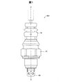
図1は、本発明の一実施形態としてのガスセンサの外観図である。以下では、図1におけるガスセンサ100の軸線Oに沿った紙面下向きの方向を先端側、紙面上向きの方向を後端側として説明する。ガスセンサ100は、例えば、オートバイ等の車両の排気ガス中の酸素濃度を計測する酸素センサである。ガスセンサ100は、その先端部分を車両の排気管内に突出させる形態で車両に固定される。
A. Gas sensor structure:
FIG. 1 is an external view of a gas sensor as one embodiment of the present invention. In the following description, the downward direction on the paper surface along the axis O of the
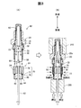
図2は、軸線Oに沿ったガスセンサ100の断面図である。ガスセンサ100は、全体として、軸線Oに沿って伸長する略円柱状の形状を有している。ガスセンサ100は、検出素子10と、主体金具20と、プロテクタ60と、内筒50と、外筒70と、を備えている。検出素子10を「センサ素子10」とも呼ぶ。
FIG. 2 is a cross-sectional view of the
検出素子10は、酸素イオン伝導性の固体電解質体の両面に一対の電極を積層した酸素濃淡電池を構成する。この検出素子10は、酸素分圧に応じた検出値を出力する公知の酸素センサ素子である。検出素子10は、外径が先端に向かってテーパ状に縮径する有底筒状の固体電解質体11と、固体電解質体11の内表面に形成された内側電極(基準電極)10aと、固体電解質体11の外表面に形成された外側電極(検出電極)10dと、を備えている。検出素子10の軸線方向における中央付近には、鍔部12が設けられている。検出素子10は、検出素子10の内部空間を基準ガス雰囲気とし、検出素子10の外表面に被検出ガスを接触させることによって、ガスの検知を行う。ガスセンサ100の後端からは、内側電極10aからの検出信号を取り出すためのリード線62が突出している。リード線62の外周には、リード線62を保護するためのガラス編組チューブ61が設けられている。このガラス編組チューブ61は省略可能である。
The
主体金具20は、検出素子10の径方向周囲を取り囲んで検出素子10を保持する筒状の部材であり、金属(例えばステンレス鋼や炭素鋼)で形成されている。主体金具20の内表面には、先端方向に向かって内径が縮径する段部20bが設けられている。また、主体金具20の軸線方向における中央付近には、取り付け工具を係合させるために、径方向外側に突出した多角形状の鍔部20cが設けられている。さらに、鍔部20cよりも先端側の外表面には、雄ねじ部20dが形成されている。主体金具20の雄ねじ部20dを、例えば自動二輪(オートバイ)の排気管のネジ孔に取付けて、検出素子10の先端を排気管内に配置することにより、ガスセンサ100を用いて被検出ガス(排気ガス)中の酸素濃度の検知が可能になる。ガスセンサ100において、鍔部20cの先端側の面と雄ねじ部20dの後端との間の段部には、さらに、ガスセンサ100を排気管に取付けた際のガス抜けを防止するガスケット29が嵌挿される。
The
検出素子10の鍔部12よりも後端側の部分と、主体金具20との間の空隙には、滑石粉末が圧縮充填された粉体充填部31が配置されている。この粉体充填部31により、検出素子10と主体金具20との隙間がシールされている。粉体充填部31の後端側には、筒状の絶縁部材(セラミックスリーブ)32が配置されている。
A
プロテクタ60は、有底筒状の金属製部材であり、主体金具20から先端側に突出する検出素子10の先端部を覆っている。プロテクタ60には、排気ガスをプロテクタ60の内部に取り込むための複数の孔部64が形成されている。この複数の孔部64からプロテクタ60内に流入した排気ガスは、被検出ガスとして外側電極10dに供給される。
The
内筒50は、主体金具20に取り付けられるとともに主体金具20よりも軸線方向の後端側に延びる筒状の部材である。また、内筒50は、主体金具20の後端部に固定されて検出素子10の後端部分を覆っている。内筒50は、例えば、SUS430、SUS304、SUS304L、SUS310S、SUS316、SUS316L等のステンレス鋼、または、炭素鋼等の金属で形成することができる。主体金具20の後端部の内表面と、内筒50の先端部の外表面との間には、例えばステンレス鋼や炭素鋼により形成される金属リング33が配置されている。内筒50の先端部は、金属リング33と絶縁部材32との間に挟持された状態で、主体金具20の後端部に設けられた加締部22により固定されている。すなわち、主体金具20の後端部が加締められて加締部22が形成されることにより、金属リング33と絶縁部材32との間に内筒50の先端部が固定される。また、この加締めにより、絶縁部材32が先端側に押し付けられて粉体充填部31が押し潰され、絶縁部材32および粉体充填部31が加締められて固定されるとともに、検出素子10と主体金具20の隙間がシールされる。
The
内筒50の内側には、略円筒形状で絶縁性のセパレータ34が配置されている。セパレータ34には、軸線O方向に貫通し、リード線62が挿通される挿通孔35が形成されている。セパレータ34の外面は、内筒50の内面から離れており、外気が流通可能とされている。
A substantially cylindrical and insulating
リード線62の先端側には、接続端子65が電気的に接続されている。接続端子65は、センサ出力を外部に取り出すための部材であり、セパレータ34よりも先端側に突出している。この接続端子65は、内側電極10aと電気的に接続するように検出素子10内に挿入されている。
A
内筒50の内側には、セパレータ34の後端に接して、シール部材としての略円筒形状のグロメット40が配置されている。グロメット40には、軸線O方向に貫通し、リード線62が挿通される挿通孔42が形成されている。グロメット40は、例えば、シリコンゴムやフッ素ゴム等のゴム材料によって形成することができる。グロメット40は、先端側に円筒状の胴部43を有し、胴部の後端に胴部43よりも拡径した鍔部44を有している。鍔部44は、外筒70の内側後端に圧入されている。胴部43は、内筒50の後端部を介して外筒70により加締められている。
Inside the
内筒50の側面のうち、グロメット40が配置される位置よりも先端側の位置には、複数の第1通気孔51が周方向に並んで開口している。そして、内筒50の外側には、第1通気孔51を覆うように、筒状の通気フィルタ30が配置されている。内筒50および通気フィルタ30の外側には、さらに、金属製の筒状の外筒70が配置されている。
In the side surface of the
外筒70は、内筒50の径方向周囲を取り囲むように配置された筒状の部材である。外筒70は、例えば、SUS430、SUS304、SUS304L、SUS310S、SUS316、SUS316L等のステンレス鋼や炭素鋼等の金属によって形成することができる。外筒70の側面には、複数の第2通気孔74が周方向に並んで開口している。その結果、外筒70の第2通気孔74と、通気フィルタ30と、内筒50の第1通気孔51とを介して、内筒50の内部、さらには検出素子10の内側電極10aへと、外気を導入可能になっている。また、外筒70の後端部は径方向内側に折れ曲げられており、この後端部にグロメット40の鍔部44の後端面が当接している。また、外筒70の後端部における径方向の中央にはリード線62が挿通する開口部が設けられている。
The
外筒70は、内筒50とともに径方向内側に加締められることによって、内筒50の外周に固定される。本実施形態では、この加締めによって、外筒70に、凹状の3つの加締部71〜73が先端側から順に形成されている。第1加締部71は、第2通気孔74よりも先端側に形成されている。第2加締部72は、第2通気孔74よりも後端側に形成されている。第1加締部71と第2加締部72の間の部分は、第1加締部71及び第2加締部72よりも径方向外側に突出した凸状突出部75として形成されている。凸状突出部75は、複数の第2通気孔74を含んでいる。第3加締部73は、内筒50の後端を含むように、グロメット40の胴部43の周囲に形成されている。
The
通気フィルタ30は、径方向における内筒50と外筒70との間に挟持されており、第2通気孔74の先端側と後端側の位置に設けられた外筒70の加締部71,72によって固定されている。通気フィルタ30は、非透水性で通気性の中空筒状部材であり、例えばフッ素系樹脂等の撥水性樹脂の多孔質構造体によって構成することができる。通気フィルタ30は、撥水性を有しているため、外部の水を通さずに検出素子10の内部空間に基準ガス(大気)を導入可能となっている。
The
B.ガスセンサの製造方法の第1実施形態:
図3は、第1実施形態におけるガスセンサの製造方法の一部の工程を示す説明図である。なお、図3では図示の便宜上、図1,図2とは上下(先端と後端)を逆に描いている。
B. First Embodiment of Gas Sensor Manufacturing Method:
Drawing 3 is an explanatory view showing a part of process of the manufacturing method of the gas sensor in a 1st embodiment. In FIG. 3, for convenience of illustration, the top and bottom (the front end and the rear end) are drawn upside down from FIGS.
図3(A)は、セパレータアッセンブリ81と検出素子アッセンブリ82の組み付け工程を示している。セパレータアッセンブリ81は、接続端子65及びリード線62の後端からセパレータ34とグロメット40と外筒70とを順に挿入した組立体である。外筒70の加締めを行う前の状態では、外筒70は、後端側の小径部76と、先端側の大径部78と、それらの間の段差部77とを有する。小径部76と大径部78は、それぞれ中空の直円筒状の形状を有している。なお、大径部78の軸線方向における中央付近には、図2で説明した複数の第2通気孔74が設けられているが、図3では図示を省略している。
FIG. 3A shows an assembling process of the
検出素子アッセンブリ82は、主体金具20と、検出素子10と、内筒50と、プロテクタ60と、通気フィルタ30と、絶縁部材32と、粉体充填部31と、金属リング33と、が組み付けられた組立体である。主体金具20の後端部には加締部22が設けられており、この加締部22によって内筒50が主体金具20に固定されている。通気フィルタ30は、その先端が主体金具20の加締部22に接した状態で内筒50の外周に設置されている。この状態では、通気フィルタ30は、中空の直円筒状の形状を有している。
In the
セパレータアッセンブリ81と検出素子アッセンブリ82の組み付けは、検出素子アッセンブリ82に含まれる内筒50の後端を、セパレータアッセンブリ81に形成された空間90に挿入しつつ、セパレータアッセンブリ81の接続端子65を、検出素子10の内部に挿入することによって行われる。この組み付けにより、リード線62と検出素子10とが電気的に接続される。また、セパレータ34とグロメット40の胴部43とが内筒50内に配置され、更に、外筒70が内筒50の外周に配置され、外筒70の後端部と内筒50の後端面との間にグロメット40の鍔部44が配置される状態となる。また、通気フィルタ30は、内筒50と外筒70の間の空間に挿入された状態で、主体金具20の加締部22と外筒70の段差部77との間に保持される。この工程は、内筒50と外筒70との間に通気フィルタ30を挟持する挟持工程に相当する。
The assembly of the
セパレータアッセンブリ81と検出素子アッセンブリ82との組み付けが終了すると、図3(B)に示すように、外筒70を径方向内側に加締める加締め工程が実行される。外筒70の加締めは、図3(B)の破線で示した3カ所の位置で行われ、図2で説明した3つの加締部71〜73と凸状突出部75が形成される。これらの加締部71〜73のそれぞれは、例えば、周方向に複数(例えば4個)に分割された分割リング状の加締め治具を使用することによって形成可能である。また、第1実施形態において、この加締めは、主体金具20の鍔部20cの先端側に配置された第1治具210と、外筒70の後端側に配置された第2治具220とによって、外筒70が主体金具20側に押圧された状態で行われる。この押圧は、通気フィルタ30を軸線方向に圧縮するためのものである。
When the assembly of the
図4は、外筒70の加締め工程の前後におけるガスセンサの外観を示す図である。外筒70の加締めが実行されると、外筒70の外周に、3つの加締部71〜73と凸状突出部75とが形成される。凸状突出部75の軸線方向における中央付近には、凸状突出部75の周方向に沿って複数の第2通気孔74が設けられている。この例では、第2通気孔74は、90度おきに4つ設けられている。
FIG. 4 is a view showing the appearance of the gas sensor before and after the caulking process of the
図5は、外筒70の加締め後におけるガスセンサの通気構造の縦断面図である。図5(A)は、ガスセンサの後端部の縦断面の一部を示しており、図5(B)は、第2通気孔74近傍の部分Bを拡大して示している。図5(A),(B)に示すように、通気フィルタ30は、その外表面が凸状突出部75の内面に沿って接触しつつ外側に湾曲した形状を有する。このような通気フィルタ30の形状は、図3(B)で説明したように、通気フィルタ30を軸線方向に沿って圧縮しつつ外筒70を加締めて、外筒70に、第1加締部71と第2加締部72とその間の凸状突出部75とを形成することによって得ることができる。すなわち、外筒70の加締め時に通気フィルタ30が軸線方向に沿って圧縮されているので、外筒70に凸状突出部75が形成されると、通気フィルタ30の外表面が凸状突出部75の内面に接触したまま変形し、外側に湾曲した形状となる。こうすれば、外筒70の第2通気孔74から水が内部に侵入しにくいので、良好な耐水圧性を得ることが可能である。なお、耐水圧性の観点からは、通気フィルタ30の外表面が、凸状突出部75のうちで、特に、第2通気孔74の周縁部分の内面に接触又は密着した状態となることが好ましい。
FIG. 5 is a longitudinal cross-sectional view of the gas sensor ventilation structure after the
図5(C)は、比較例における外筒70の凸状突出部75と通気フィルタ30の状態を示している。この比較例では、通気フィルタ30の外表面が凸状突出部75の内面に接触しておらず、両者の間に隙間Gが形成されている。従って、例えば高圧の水が外筒70の第2通気孔74に当たった場合には、高圧の水がガスセンサの中に進入してしまう可能性が高いという問題がある。
FIG. 5C shows a state of the projecting
一方、図5(A),(B)に示す第1実施形態のガスセンサでは、外筒70の凸状突出部75と通気フィルタ30との間に水が通りうる隙間が無いので、シール性が高く、十分な耐水圧性を有する。すなわち、高圧の水が外筒70の第2通気孔74に当たった場合にも、高圧の水がガスセンサの中に進入してしまう可能性を低減できる。
On the other hand, in the gas sensor of the first embodiment shown in FIGS. 5A and 5B, there is no gap through which water can pass between the protruding
C.ガスセンサの製造方法の第2実施形態:
図6は、第2実施形態における外筒70の加締め工程の前後におけるガスセンサの外観を示す図である。図6(A),(B)は、第1実施形態における図4(A),(B)とほぼ同様の外筒70の加締め工程を示しているが、図6(A)に示す加締め時において、外筒70が軸線方向に押圧されていない点が第1実施形態と異なる。すなわち、第2実施形態では、外筒70の加締め時に、通気フィルタ30をガスセンサの軸線方向に沿って圧縮していない。
C. Second Embodiment of Gas Sensor Manufacturing Method:
FIG. 6 is a diagram illustrating an appearance of the gas sensor before and after the caulking process of the
図6(C)は、図6(A),(B)に示す加締め工程の後に行われる整形工程を示している。この整形工程では、治具230を用いて凸状突出部75の第2通気孔74の周縁部分を外から押し込むことによって、凸状突出部75を整形する。
FIG. 6C shows a shaping process performed after the caulking process shown in FIGS. In this shaping step, the
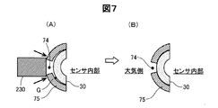
図7は、凸状突出部75の整形工程の前後のガスセンサの通気構造の縦断面図であり、第1実施形態の図5(B)に相当する図である。図7(A)に示すように、凸状突出部75の整形工程前は、通気フィルタ30の外表面が凸状突出部75の内面(第2通気孔74の周縁部分の内面)に接触しておらず、両者の間に隙間Gが形成されている。そこで、治具230を用いて凸状突出部75の第2通気孔74の周縁部分を外から押し込む整形工程を実行すると、この隙間Gをなくすことができる。この結果、図7(B)に示すように、凸状突出部75の内面に通気フィルタ30の外表面が接触した形状となる。換言すれば、第2実施形態においても、第1実施形態と同様に、通気フィルタ30の外表面が、凸状突出部75の内面に沿って接触しつつ外側に湾曲した形状を有するものとなる。
FIG. 7 is a longitudinal sectional view of the gas sensor ventilation structure before and after the shaping process of the
このように、第2実施形態においても、外筒70の凸状突出部75と通気フィルタ30との間に外部からの水が浸入し得る隙間が無い構造が得られるので、シール性が高く、十分な耐水圧性を有するガスセンサを提供できる。すなわち、高圧の水が外筒70の第2通気孔74に当たった場合にも、高圧の水がガスセンサの中に進入してしまう可能性を低減できる。
As described above, also in the second embodiment, a structure without a gap through which water from the outside can enter is obtained between the
なお、図6では、図6(A),(B)の外筒70の加締め工程の後に図6(C)の整形工程を実行するものとしたが、整形工程を加締め工程と同時に行うようにしても良い。また、図6の例では、外筒70の加締め時において通気フィルタ30を軸線方向に圧縮しないものとしたが、第1実施形態と同様に、通気フィルタ30を軸線方向に圧縮しつつ外筒70の加締めを行うようにしても良い。この場合にも、図6(C)に示す整形工程を実行することによって、通気フィルタ30の外表面が凸状突出部75の内面に沿って接触しつつ外側に湾曲した形状を有する構造を、より確実に得ることが可能である。
In FIG. 6, the shaping process of FIG. 6C is executed after the caulking process of the
D.変形例:
なお、この発明は上記の実施例や実施形態に限られるものではなく、その要旨を逸脱しない範囲において種々の態様において実施することが可能である。
D. Variations:
In addition, this invention is not restricted to said Example and embodiment, In the range which does not deviate from the summary, it is possible to implement in various aspects.
・変形例1:
上述した実施形態のガスセンサの構成は例示であり、本発明はこれ以外の種々の構成を有するガスセンサにも適用可能である。
・ Modification 1:
The configuration of the gas sensor of the above-described embodiment is an exemplification, and the present invention is applicable to gas sensors having various configurations other than this.
10…検出素子
10a…内側電極
10d…外側電極
11…固体電解質体
12…鍔部
20…主体金具
20b…段部
20c…鍔部
20d…雄ねじ部
22…加締部
29…ガスケット
30…通気フィルタ
31…粉体充填部
32…絶縁部材
33…金属リング
34…セパレータ
35…挿通孔
40…グロメット
42…挿通孔
43…胴部
44…鍔部
50…内筒
51…第1通気孔
60…プロテクタ
61…ガラス編組チューブ
62…リード線
64…孔部
65…接続端子
70…外筒
71…第1加締部
72…第2加締部
73…第3加締部
74…第2通気孔
75…凸状突出部
76…小径部
77…段差部
78…大径部
81…セパレータアッセンブリ
82…検出素子アッセンブリ
90…空間
100…ガスセンサ
210…第1治具
220…第2治具
230…治具
DESCRIPTION OF
Claims (4)
前記外筒は、前記第2通気孔よりも前記軸線方向の先端側にある第1加締部と、前記第2通気孔よりも前記軸線方向の後端側にある第2加締部と、前記第2通気孔を含み前記第1加締部及び前記第2加締部よりも径方向外側に突出した凸状突出部と、を有し、
前記通気フィルタの外表面は、前記凸状突出部の内面に沿って接触しつつ径方向外側に湾曲した形状を有することを特徴とするガスセンサ。 A detection element extending in the axial direction, a cylindrical metal shell that surrounds the periphery of the detection element in the radial direction and holds the detection element, and a rear end side in the axial direction with respect to the metal shell that is attached to the metal shell A cylindrical inner cylinder having a first ventilation hole, a cylindrical outer cylinder having a second ventilation hole disposed so as to surround the radial circumference of the inner cylinder, and the inner cylinder in the radial direction. A gas sensor having a water impermeable ventilation filter sandwiched between the outer cylinder,
The outer cylinder includes a first crimping portion located on the distal end side in the axial direction with respect to the second vent hole, and a second crimping portion located on the rear end side in the axial direction with respect to the second vent hole; A convex projecting portion including the second vent hole and projecting radially outward from the first caulking portion and the second caulking portion,
The gas sensor according to claim 1, wherein an outer surface of the ventilation filter has a shape curved radially outward while contacting along an inner surface of the convex protrusion.
前記内筒と前記外筒との間に前記通気フィルタを挟持する挟持工程と、
前記通気フィルタを前記軸線方向に沿って圧縮しつつ前記外筒を径方向内側に加締めることによって、前記外筒に、前記第2通気孔よりも前記軸線方向の先端側にある第1加締部と、前記第2通気孔よりも前記軸線方向の後端側にある第2加締部と、前記第2通気孔を含み前記第1加締部及び前記第2加締部よりも径方向外側に突出した凸状突出部と、を形成するとともに、前記通気フィルタの外表面が前記凸状突出部の内面に沿って接触しつつ径方向外側に湾曲した形状を有するように前記通気フィルタを変形させる加締め工程と、
を備えることを特徴とするガスセンサの製造方法。 A detection element extending in the axial direction, a cylindrical metal shell that surrounds the periphery of the detection element in the radial direction and holds the detection element, and a rear end side in the axial direction with respect to the metal shell that is attached to the metal shell A cylindrical inner cylinder having a first ventilation hole, a cylindrical outer cylinder having a second ventilation hole disposed so as to surround the radial circumference of the inner cylinder, and the inner cylinder in the radial direction. A non-water-permeable ventilation filter sandwiched between the outer cylinder and a gas sensor manufacturing method comprising:
A clamping step of clamping the ventilation filter between the inner cylinder and the outer cylinder;
The outer cylinder is crimped inward in the radial direction while compressing the ventilation filter along the axial direction, whereby the first crimping is located on the outer cylinder on the distal end side in the axial direction with respect to the second ventilation hole. Part, a second crimping portion located on the rear end side in the axial direction with respect to the second vent hole, and a radial direction with respect to the first crimping portion and the second crimping portion including the second vent hole A convex protrusion that protrudes outward, and the outer surface of the vent filter has a shape that is curved radially outward while contacting the inner surface of the convex protrusion. A caulking step to deform,
A method of manufacturing a gas sensor, comprising:
前記内筒と前記外筒との間に前記通気フィルタを挟持する挟持工程と、
前記外筒を径方向内側に加締めることによって、前記外筒に、前記第2通気孔よりも前記軸線方向の先端側にある第1加締部と、前記第2通気孔よりも前記軸線方向の後端側にある第2加締部と、前記第2通気孔を含み前記第1加締部及び前記第2加締部よりも径方向外側に突出した凸状突出部と、を形成する加締め工程と、
前記加締め工程と同時、又は、前記加締め工程の後に、前記外筒の前記凸状突出部の前記第2通気孔の周縁部分を外側から押し込むことによって、前記凸状突出部の内面に沿って前記通気フィルタの外表面を接触させるように前記凸状突出部を整形する整形工程と、
を備えることを特徴とするガスセンサの製造方法。 A detection element extending in the axial direction, a cylindrical metal shell that surrounds the periphery of the detection element in the radial direction and holds the detection element, and a rear end side in the axial direction with respect to the metal shell that is attached to the metal shell A cylindrical inner cylinder having a first ventilation hole, a cylindrical outer cylinder having a second ventilation hole disposed so as to surround the radial circumference of the inner cylinder, and the inner cylinder in the radial direction. A non-water-permeable ventilation filter sandwiched between the outer cylinder and a gas sensor manufacturing method comprising:
A clamping step of clamping the ventilation filter between the inner cylinder and the outer cylinder;
By caulking the outer cylinder inward in the radial direction, the outer cylinder is provided with a first crimping portion located on the distal end side in the axial direction with respect to the second ventilation hole, and the axial direction with respect to the second ventilation hole. A second caulking portion on the rear end side, and a convex projecting portion including the second ventilation hole and projecting radially outward from the first caulking portion and the second caulking portion. Caulking process;
Simultaneously with the caulking step or after the caulking step, by pushing the peripheral edge portion of the second vent hole of the convex protrusion of the outer cylinder from the outside, along the inner surface of the convex protrusion A shaping step of shaping the convex protrusion so as to contact the outer surface of the ventilation filter;
A method of manufacturing a gas sensor, comprising:
前記加締め工程は、前記通気フィルタを前記軸線方向に沿って圧縮しながら行われることを特徴とするガスセンサの製造方法。 It is a manufacturing method of the gas sensor according to claim 3,
The method of manufacturing a gas sensor, wherein the caulking step is performed while compressing the ventilation filter along the axial direction.
Priority Applications (1)
| Application Number | Priority Date | Filing Date | Title |
|---|---|---|---|
| JP2016093787A JP2017203632A (en) | 2016-05-09 | 2016-05-09 | Gas sensor and manufacturing method for the same |
Applications Claiming Priority (1)
| Application Number | Priority Date | Filing Date | Title |
|---|---|---|---|
| JP2016093787A JP2017203632A (en) | 2016-05-09 | 2016-05-09 | Gas sensor and manufacturing method for the same |
Publications (1)
| Publication Number | Publication Date |
|---|---|
| JP2017203632A true JP2017203632A (en) | 2017-11-16 |
Family
ID=60322147
Family Applications (1)
| Application Number | Title | Priority Date | Filing Date |
|---|---|---|---|
| JP2016093787A Pending JP2017203632A (en) | 2016-05-09 | 2016-05-09 | Gas sensor and manufacturing method for the same |
Country Status (1)
| Country | Link |
|---|---|
| JP (1) | JP2017203632A (en) |
Cited By (2)
| Publication number | Priority date | Publication date | Assignee | Title |
|---|---|---|---|---|
| JP2019203849A (en) * | 2018-05-25 | 2019-11-28 | 日本特殊陶業株式会社 | Sensor |
| JP2020003395A (en) * | 2018-06-29 | 2020-01-09 | 日本特殊陶業株式会社 | Sensor |
-
2016
- 2016-05-09 JP JP2016093787A patent/JP2017203632A/en active Pending
Cited By (4)
| Publication number | Priority date | Publication date | Assignee | Title |
|---|---|---|---|---|
| JP2019203849A (en) * | 2018-05-25 | 2019-11-28 | 日本特殊陶業株式会社 | Sensor |
| JP7021002B2 (en) | 2018-05-25 | 2022-02-16 | 日本特殊陶業株式会社 | Sensor |
| JP2020003395A (en) * | 2018-06-29 | 2020-01-09 | 日本特殊陶業株式会社 | Sensor |
| JP7068071B2 (en) | 2018-06-29 | 2022-05-16 | 日本特殊陶業株式会社 | Sensor |
Similar Documents
| Publication | Publication Date | Title |
|---|---|---|
| JP4955591B2 (en) | Gas sensor | |
| JP5592336B2 (en) | Gas sensor | |
| JP5529070B2 (en) | Gas sensor | |
| JP5310170B2 (en) | Gas sensor and manufacturing method thereof | |
| JP5032625B2 (en) | Gas sensor | |
| JP2011215095A (en) | Gas sensor | |
| JP5514239B2 (en) | In-vehicle sensor | |
| JP2017203632A (en) | Gas sensor and manufacturing method for the same | |
| JP4693115B2 (en) | Gas sensor | |
| JP5925089B2 (en) | Gas sensor | |
| JP5919132B2 (en) | Gas sensor | |
| JP5753818B2 (en) | Gas sensor | |
| JP6622604B2 (en) | Gas sensor and gas sensor manufacturing method | |
| JP2007271516A (en) | Gas sensor | |
| JP6607797B2 (en) | Gas sensor | |
| JP4763645B2 (en) | Sensor | |
| JP5662280B2 (en) | Gas sensor | |
| JP6316580B2 (en) | Gas sensor | |
| JP5102167B2 (en) | Sensor | |
| JP7126900B2 (en) | gas sensor | |
| JP5767196B2 (en) | Gas sensor | |
| JP2018080952A (en) | Gas sensor | |
| JP5135252B2 (en) | Gas sensor | |
| JP2014149181A (en) | Gas sensor and method of manufacturing the same | |
| JP2010276337A (en) | Gas sensor |