JP2017203437A - Piston for internal combustion engine - Google Patents
Piston for internal combustion engine Download PDFInfo
- Publication number
- JP2017203437A JP2017203437A JP2016096384A JP2016096384A JP2017203437A JP 2017203437 A JP2017203437 A JP 2017203437A JP 2016096384 A JP2016096384 A JP 2016096384A JP 2016096384 A JP2016096384 A JP 2016096384A JP 2017203437 A JP2017203437 A JP 2017203437A
- Authority
- JP
- Japan
- Prior art keywords
- outer peripheral
- piston
- heat shield
- shield layer
- top surface
- Prior art date
- Legal status (The legal status is an assumption and is not a legal conclusion. Google has not performed a legal analysis and makes no representation as to the accuracy of the status listed.)
- Pending
Links
Images


Classifications
-
- Y—GENERAL TAGGING OF NEW TECHNOLOGICAL DEVELOPMENTS; GENERAL TAGGING OF CROSS-SECTIONAL TECHNOLOGIES SPANNING OVER SEVERAL SECTIONS OF THE IPC; TECHNICAL SUBJECTS COVERED BY FORMER USPC CROSS-REFERENCE ART COLLECTIONS [XRACs] AND DIGESTS
- Y02—TECHNOLOGIES OR APPLICATIONS FOR MITIGATION OR ADAPTATION AGAINST CLIMATE CHANGE
- Y02T—CLIMATE CHANGE MITIGATION TECHNOLOGIES RELATED TO TRANSPORTATION
- Y02T10/00—Road transport of goods or passengers
- Y02T10/10—Internal combustion engine [ICE] based vehicles
- Y02T10/12—Improving ICE efficiencies
Landscapes
- Combustion Methods Of Internal-Combustion Engines (AREA)
Abstract
Description
本発明は、内燃機関用ピストンに関するものである。 The present invention relates to a piston for an internal combustion engine.
従来、エンジン部品のような高温ガスに晒される金属製品では、高温ガスからの熱伝達、すなわち冷却損失を抑制するために、その金属製母材の表面に遮熱層を形成することが行われている。その一例として、エンジンの燃焼室を区画するピストン本体の頂面に、ジルコニア等の無機酸化物や、中空粒子を含有する有機系材料からなる遮熱層を形成することが知られている。 Conventionally, in metal products exposed to high temperature gas such as engine parts, in order to suppress heat transfer from the high temperature gas, that is, cooling loss, a heat shielding layer is formed on the surface of the metal base material. ing. As an example, it is known to form a heat shield layer made of an organic material containing inorganic oxides such as zirconia and hollow particles on the top surface of a piston main body that defines a combustion chamber of an engine.
ところで、燃焼室を区画するピストン本体の頂面とシリンダヘッドの下面との間隙部にスキッシュエリアが形成されることがある。このようなピストン本体の頂面のうち、スキッシュエリアを形成する面(スキッシュエリア面)に遮熱層が設けられている場合、当該遮熱層の温度は高温となり、延いてはスキッシュエリア面自体が高温となる。このため、燃焼工程において、スキッシュエリアに高温高圧のエンドガス(点火プラグから遠い場所にある未燃焼の混合気)が流れ込んだ際に、高温のスキッシュエリア面により、エンドガスからスキッシュエリア面への放熱が妨げられて、ノッキングが発生し得る。そして、スキッシュエリア面に形成された遮熱層にクラックが生じ、遮熱層の損傷・剥離が引き起こされ、遮熱性能が失われる。 By the way, a squish area may be formed in the gap between the top surface of the piston body that defines the combustion chamber and the lower surface of the cylinder head. When the heat shield layer is provided on the surface (squish area surface) that forms the squish area of the top surface of the piston body, the temperature of the heat shield layer becomes high, and the squish area surface itself Becomes hot. For this reason, in the combustion process, when high-temperature and high-pressure end gas (unburned gas mixture far from the spark plug) flows into the squish area, heat is dissipated from the end gas to the squish area by the high-temperature squish area. Blocked and knocking can occur. And a crack arises in the thermal insulation layer formed in the squish area surface, damage and peeling of a thermal insulation layer are caused, and thermal insulation performance is lost.
そこで、ピストン本体の頂面のうち、スキッシュエリア面上には遮熱層を形成せず、それ以外の部分にのみ遮熱層を形成した内燃機関が記載されている(例えば、特許文献1参照)。 Thus, an internal combustion engine is described in which a heat shield layer is not formed on the squish area surface of the top surface of the piston body, and a heat shield layer is formed only in other portions (for example, see Patent Document 1). ).
特許文献1の内燃機関によれば、スキッシュエリア面上には遮熱層を形成していないので、エンドガスからのスキッシュエリア面への放熱が促進され、ノッキングの発生が抑制される。 According to the internal combustion engine of Patent Document 1, since a heat shield layer is not formed on the squish area surface, heat radiation from the end gas to the squish area surface is promoted, and the occurrence of knocking is suppressed.
しかしながら、特許文献1の構成では、遮熱層を形成していない領域の冷却損失を低減することができない。また、遮熱層を形成した部位と遮熱層を形成していない部位との境界に遮熱層の厚さに起因する段差が生じるため、乱流が発生し、ピストン外周部での冷却損失が増大する虞がある。 However, with the configuration of Patent Document 1, it is not possible to reduce the cooling loss in the region where the heat shield layer is not formed. In addition, a step due to the thickness of the heat shield layer occurs at the boundary between the part where the heat shield layer is formed and the part where the heat shield layer is not formed. May increase.
そこで、本発明では、スキッシュエリア面に遮熱層を形成しつつ、ノッキングによる当該遮熱層の損傷・剥離を抑えるとともに、スキッシュエリアにおいて乱流の発生を防止し冷却損失を低減させることができる内燃機関用ピストンをもたらすことを目的とする。 Therefore, in the present invention, while forming a heat shield layer on the squish area surface, it is possible to suppress damage and separation of the heat shield layer due to knocking, and to prevent generation of turbulent flow in the squish area and reduce cooling loss. The object is to provide a piston for an internal combustion engine.
上記の目的を達成するために、本発明では、ピストン本体頂面のスキッシュエリア面を含む外周側に設けられた遮熱層と、その内周側に設けられた遮熱層との境界を段差なく滑らかに接続させるようにした。 In order to achieve the above object, in the present invention, a step is formed between the boundary between the heat shield layer provided on the outer peripheral side including the squish area surface of the top surface of the piston body and the heat shield layer provided on the inner peripheral side thereof. The connection was made smoothly.
すなわち、ここに開示する内燃機関用ピストンは、頂面外周側に内燃機関燃焼室のスキッシュエリアを形成するスキッシュエリア面を備えたピストン本体と、前記ピストン本体の頂面に形成された遮熱層と、を備えた内燃機関用ピストンであって、前記遮熱層は、前記ピストン本体の頂面の少なくとも前記スキッシュエリア面を含む外周側に形成され、該ピストン本体頂面の径方向内周側から外周側に向かって厚さが次第に減少している外周部と、前記ピストン本体の頂面において前記外周部よりも内周側に形成され、外周側端部表面が前記外周部の内周側端部表面から滑らかに接続されるように形成された内周部と、を備えたことを特徴とする。 That is, a piston for an internal combustion engine disclosed herein includes a piston body having a squish area surface that forms a squish area of an internal combustion engine combustion chamber on the outer peripheral side of the top surface, and a heat shield layer formed on the top surface of the piston body. The heat shield layer is formed on the outer peripheral side including at least the squish area surface of the top surface of the piston main body, and the radially inner peripheral side of the piston main body top surface An outer peripheral portion whose thickness gradually decreases from the outer peripheral side toward the outer peripheral side, and an inner peripheral side of the outer peripheral portion at the top surface of the piston body, and an outer peripheral end surface is an inner peripheral side of the outer peripheral portion And an inner periphery formed so as to be smoothly connected from the end surface.
本発明によれば、遮熱層における内周部の外周側端部と外周部の内周側端部との境界において、表面が滑らかに接続されているので、遮熱層表面での乱流発生を抑制し、冷却損失を低減させることができる。また、外周部はスキッシュエリア面全体を覆うように形成されており、ピストン本体頂面外周側に向かって次第に膜厚が減少するように設定されているので、スキッシュエリアでノッキングが生じてもクラックの成長を抑制し、遮熱層の損傷・剥離を抑えることができる。 According to the present invention, since the surface is smoothly connected at the boundary between the outer peripheral end of the inner peripheral portion and the inner peripheral end of the outer peripheral portion of the heat shield layer, the turbulent flow on the surface of the heat shield layer Generation | occurrence | production can be suppressed and a cooling loss can be reduced. In addition, the outer peripheral part is formed so as to cover the entire squish area surface, and since the film thickness is gradually reduced toward the outer peripheral side of the top surface of the piston body, cracks are generated even if knocking occurs in the squish area. It is possible to suppress the growth of the heat shield layer and to prevent damage and peeling of the heat shield layer.
好ましい態様では、前記遮熱層の外周部は、前記ピストン本体頂面の径方向内周側から外周側に向かって厚さが段差なく連続的に減少するように形成されている。これにより、外周部表面も段差なく滑らかに形成されているので、遮熱層表面での乱流発生の抑制効果をより高めることができる。 In a preferred aspect, the outer peripheral portion of the heat shield layer is formed such that the thickness continuously decreases without a step from the radially inner peripheral side to the outer peripheral side of the piston main body top surface. Thereby, since the outer peripheral part surface is also formed smoothly without a level | step difference, the suppression effect of turbulent flow generation | occurrence | production on the surface of a thermal-insulation layer can be heightened more.
なお、本明細書において、「段差なし」とは、前記遮熱層の外周部表面並びに前記遮熱層の外周部及び内周部の境界部に、高低差10μm以上、円筒状のピストン本体の軸に対する傾斜角度が20°以内の傾斜がないことをいう。 In the present specification, “no step” means that the difference in height between the outer peripheral surface of the heat shield layer and the boundary between the outer peripheral portion and the inner peripheral portion of the heat shield layer is 10 μm or more. It means that there is no inclination within an inclination angle of 20 ° with respect to the axis.
好ましい態様では、前記遮熱層の内周部及び外周部により、前記ピストン本体頂面の全面が覆われている。これにより、ピストン本体の頂面全体で優れた遮熱性能を得つつ、遮熱層の損傷・剥離を効果的に抑えることができる。 In a preferred embodiment, the entire top surface of the piston body is covered with the inner and outer peripheral portions of the heat shield layer. Accordingly, it is possible to effectively suppress damage and peeling of the heat shield layer while obtaining excellent heat shield performance over the entire top surface of the piston body.
好ましい態様では、前記遮熱層の外周部の外周側端部厚さは、該外周部の内周側端部厚さの20%以上60%以下である。 In a preferred aspect, the outer peripheral side end thickness of the outer peripheral portion of the heat shielding layer is 20% or more and 60% or less of the inner peripheral side end thickness of the outer peripheral portion.
外周部における径方向断面の勾配が大きすぎると、段差が形成されている状態と同様に乱流が発生する虞がある。本構成とすることにより、乱流の発生を効果的に防止することができる。 If the gradient of the radial cross section at the outer peripheral portion is too large, turbulence may occur as in the state where the step is formed. With this configuration, it is possible to effectively prevent the occurrence of turbulence.
好ましい態様では、前記遮熱層の外周部の径方向幅は、前記ピストン本体頂面外径の5%以上30%以内である。 In a preferred embodiment, the radial width of the outer peripheral portion of the heat shield layer is not less than 5% and not more than 30% of the outer diameter of the piston body top surface.
外周部エリアを大きくしすぎると、遮熱層全体に占める厚さの薄い領域の割合が高くなり、遮熱性能が低下する虞がある。本構成によれば、遮熱層の耐久性と遮熱性能とを両立させることができる。 If the outer peripheral area is too large, the proportion of the thin region in the entire heat shield layer increases, which may reduce the heat shield performance. According to this configuration, it is possible to achieve both the durability of the heat shield layer and the heat shield performance.
好ましい態様では、前記遮熱層の内周部の厚さは一定である。 In a preferred aspect, the thickness of the inner peripheral portion of the heat shield layer is constant.
これにより、ピストン本体頂面内周側では均一な厚さの遮熱層が形成されているので、優れた遮熱性能を得ることができる。 Thereby, since the heat-insulating layer having a uniform thickness is formed on the inner peripheral side of the top surface of the piston body, an excellent heat-insulating performance can be obtained.
なお、本明細書において、遮熱層の所定領域の厚さが一定とは、所定領域の遮熱層の厚さが、その平均厚さから10%前後の範囲内の厚さに設定されていることをいう。 In the present specification, the constant thickness of the predetermined region of the heat shield layer means that the thickness of the heat shield layer in the predetermined region is set to a thickness within a range of about 10% from the average thickness. It means being.
好ましい態様では、前記遮熱層は、多数の中空粒子と、前記中空粒子を前記ピストン本体の頂面に保持するとともに、前記中空粒子間を埋めて前記遮熱層の母材を形成するバインダと、を含む。これにより、遮熱層の遮熱性能を効果的に向上させることができる。 In a preferred embodiment, the heat shield layer includes a large number of hollow particles, and a binder that holds the hollow particles on the top surface of the piston body and fills the space between the hollow particles to form a base material of the heat shield layer. ,including. Thereby, the thermal insulation performance of a thermal insulation layer can be improved effectively.
好ましい態様では、前記バインダは、シリコーン系樹脂である。これにより、遮熱層の熱伝導性を低下させることができるとともに、ピストン本体の頂面と遮熱層との優れた密着性を得ることができる。 In a preferred embodiment, the binder is a silicone resin. Thereby, while being able to reduce the thermal conductivity of a thermal insulation layer, the outstanding adhesiveness of the top surface of a piston main body and a thermal insulation layer can be acquired.
好ましい態様では、前記中空粒子は、ガラスバルーンである。これにより、遮熱層の熱伝導性を低くすることができるとともに、その強度も向上させることができる。 In a preferred embodiment, the hollow particle is a glass balloon. Thereby, while being able to make the thermal conductivity of a thermal insulation layer low, the intensity | strength can also be improved.
以上述べたように、本発明によれば、遮熱層における内周部の外周側端部と外周部の内周側端部との境界において、表面が滑らかに接続されているので、遮熱層表面での乱流発生を抑制し、冷却損失を低減させることができる。また、外周部はスキッシュエリア面全体を覆うように形成されており、ピストン本体頂面外周側に向かって次第に膜厚が減少するように設定されているので、スキッシュエリアでノッキングが生じてもクラックの成長を抑制し、遮熱層の損傷・剥離を抑えることができる。 As described above, according to the present invention, since the surface is smoothly connected at the boundary between the outer peripheral side end of the inner peripheral portion and the inner peripheral end of the outer peripheral portion in the heat shield layer, Generation of turbulent flow on the surface of the layer can be suppressed, and cooling loss can be reduced. In addition, the outer peripheral part is formed so as to cover the entire squish area surface, and since the film thickness is gradually reduced toward the outer peripheral side of the top surface of the piston body, cracks are generated even if knocking occurs in the squish area. It is possible to suppress the growth of the heat shield layer and to prevent damage and peeling of the heat shield layer.
以下、本発明の実施形態を図面に基づいて詳細に説明する。以下の好ましい実施形態の説明は、本質的に例示に過ぎず、本発明、その適用物或いはその用途を制限することを意図するものでは全くない。 Hereinafter, embodiments of the present invention will be described in detail with reference to the drawings. The following description of the preferred embodiments is merely exemplary in nature and is in no way intended to limit the invention, its application, or its application.
[第1実施形態]
<エンジンの構成>
図1に示す直噴エンジン(内燃機関)Eは、ピストン(内燃機関用ピストン)1、シリンダブロック2、シリンダヘッド3、シリンダヘッド3の内部に形成された吸気ポート5の燃焼室側開口端を開閉するように構成された吸気バルブ4、シリンダヘッド3の内部に形成された排気ポート7の燃焼室側開口端を開閉するように構成された排気バルブ6、インジェクタ8、点火プラグ9を備える。ピストン1がシリンダブロック2のシリンダボア内を往復動する。
[First Embodiment]
<Engine configuration>
A direct injection engine (internal combustion engine) E shown in FIG. 1 has a piston (internal combustion engine piston) 1, a
エンジンの燃焼室(内燃機関燃焼室)は、ピストン1の冠面10、シリンダブロック2のシリンダボア、シリンダヘッド3に形成された燃焼室壁面、吸排気バルブ4,6の傘部41,61の前面で形成される。図1及び図2に示すように、ピストン1の冠面10の略中央部には、燃焼室のキャビティを形成する凹陥状のキャビティ部11が設けられている。また、冠面10の外縁部には、燃焼室のキャビティから離れた外縁側に圧縮行程中に燃焼室の混合気の流動方向を燃焼室中央部に指向させるための段差部であるスキッシュエリアを形成するためのスキッシュエリア部12が存在する。本実施形態に係るピストン1の冠面10において、スキッシュエリア部12はスキッシュエリア部12a,12b,12c,12dからなっている。
The combustion chamber of the engine (combustion chamber of the internal combustion engine) includes a
<遮熱層>
図2及び図4に示すように、ピストン1は、該ピストン1の基材であるピストン本体19と、エンジンEの燃焼室の冷却損失低減の観点からピストン本体19の頂面10’に設けられた遮熱層21とを備えている。
<Heat shield layer>
As shown in FIGS. 2 and 4, the piston 1 is provided on the
ピストン本体19はアルミニウム合金製であり、T7処理又はT6処理の熱処理が施されている。図3に示すように、ピストン本体19の頂面10’は、上記キャビティ部11を構成するキャビティ面11’と、上記スキッシュエリア部12を構成するスキッシュエリア面12’とを備えている。なお、本実施形態におけるスキッシュエリア面12’は、図3において斜線領域として示すスキッシュエリア面12a’,12b’,12c’,12d’からなる。そして、図4において、ピストン本体19の頂面10’のうち、破線で示す位置よりも外周側がスキッシュエリア面12a’,12c’である。すなわち、図2及び図4に示すスキッシュエリア部12a,12b,12c,12dは、図3に示すピストン本体19の頂面10’のスキッシュエリア面12a’,12b’,12c’,12d’と、これらのスキッシュエリア面12a’,12b’,12c’,12d’に形成された遮熱層21とにより構成されている。
The piston
遮熱層21は、図5に示すように、中空粒子31と、バインダ材(バインダ)32とを含む層である。
As shown in FIG. 5, the
すなわち、遮熱層21は、遮熱層の遮熱性能向上の観点から、バインダ材32と、その中に分散された多数の中空粒子31とを含む。バインダ材32は、中空粒子31をピストン本体19の頂面10’に保持するとともに、中空粒子31間を埋めて遮熱層21の母材を形成する。バインダ材32は例えばシリコーン系樹脂などの低熱伝導性材料であるとともに、中空粒子31は、その内部空間に熱伝導性の低い空気を含有する。このようにバインダ材32の中に中空粒子を分散させることにより、遮熱層21を、より低熱伝導性の層としている。
That is, the
中空粒子31としては、シリカバルーン、ガラスバルーン、シラスバルーン、フライアッシュバルーン、エアロゲルバルーン等のSi系酸化物成分(例えば、シリカ(SiO2))又はAl系酸化物成分(例えば、アルミナ(Al2O3))を含有するセラミック系中空粒子を採用することが好ましく、特にガラスバルーンを採用することが好ましい。これにより、遮熱層21の熱伝導性をより低くすることができるとともに、その強度も確保することができる。
As the
なお、中空粒子31は好ましくは球状である。中空粒子31の平均粒径は、遮熱層21の遮熱性向上の観点から、好ましくは5μm以上50μm以下、より好ましくは10μm以上45μm以下、特に好ましくは15μm以上40μm以下である。遮熱層21中における中空粒子31の含有量は、遮熱層21の遮熱性向上の観点から、好ましくは5質量%以上50質量%以下、より好ましくは10質量%以上45質量%以下、特に好ましくは15質量%以上40質量%以下である。
The
バインダ材32としては、耐熱性樹脂を用いることができ、例えば低熱伝導性材料であるシリコーン系樹脂を用いることができる。シリコーン系樹脂は具体的には例えば、メチルシリコーン樹脂、メチルフェニルシリコーン樹脂に代表される、分岐度の高い3次元ポリマーからなるシリコーン系樹脂を好ましく用いることができる。シリコーン系樹脂の具体例としては、さらに例えばポリアルキルフェニルシロキサンを挙げることができる。これにより、遮熱層21の熱伝導性を低下させることができるとともに、ピストン本体19の頂面10’と遮熱層21との優れた密着性を得ることができる。
As the
ここに、遮熱層21は、図2に示すように、ピストン本体19頂面10’の少なくともスキッシュエリア面12’を含む外周側に形成された遮熱層外周部21bと、ピストン本体19頂面10’の内周側であって遮熱層外周部21bの内周側に形成された遮熱層内周部21aとを備えている。
Here, as shown in FIG. 2, the
そして、遮熱層外周部21bは、図4に示すように、ピストン本体19頂面10’の径方向内周側から外周側に向かって厚さが次第に減少するように、特に、厚さが段差なく連続的に減少するように形成されている。また、遮熱層内周部21aは、表面が遮熱層外周部21bの内周側端部から滑らかに接続されるように形成されていることを特徴とする。換言すると、遮熱層内周部21aの外周側端部表面と遮熱層外周部21bの内周側端部表面との境界部は滑らかに接続されている。以下、本構成の作用効果について述べる。
As shown in FIG. 4, the heat shield layer outer
図8に従来のピストン本体19頂面10’に設けられた遮熱層21の構造を示す。図8の遮熱層21は、スキッシュエリア面12’を含むピストン本体19頂面10’の外周側に設けられた遮熱層外周部21bと、ピストン本体19頂面10’の内周側に設けられた遮熱層内周部21aとの境界部に両者の厚みの差に起因する段差22が形成されている。この段差22の存在により、スキッシュエリア近傍において発生し得る乱流について考察する。
FIG. 8 shows the structure of the
図9に示すように、平面41上に遮熱層21を設けたモデルを作成し、ガス温度1000K、壁温度500Kと仮定したときに、スキッシュ流相当の流速7.9m/sの流動42を与えた場合の、遮熱層21の厚さ、すなわち段差22の高さhに対する、遮熱層21の上面25に発生する熱の移動量、すなわち熱流束を算出した。図10に、段差22の高さhが0の場合、すなわち平面41のみの場合の熱流束に対する比率として、高さhに対する遮熱層21の上面25上に発生する熱流束の算出結果を示す。
As shown in FIG. 9, when a model in which the
図10に示すように、段差の高さhが例えば25〜100μmの範囲の場合、段差hが0の場合に対して、熱流束は3%〜10%増加することが判る。すなわち、段差22によって筒内の流動が乱れることで、平面の熱流速より増加していることが判る。
As shown in FIG. 10, when the height h of the step is in the range of 25 to 100 μm, for example, it can be seen that the heat flux increases by 3% to 10% compared to the case where the step h is 0. That is, it can be seen that the flow rate in the cylinder is disturbed by the
このように、段差22が存在することで、スキッシュエリアで発生するスキッシュ流が乱れてスキッシュエリア近傍に滞留し得る。そうすると、スキッシュ流の熱がシリンダブロック2のシリンダボア壁面等に逃げてしまい、冷却損失の増加につながる。
Thus, the presence of the
本実施形態では、上述の構成とすることにより、遮熱層21における遮熱層内周部21aの外周側端部と遮熱層外周部21bの内周側端部との境界部において、両者の表面が滑らかに接続されているので、遮熱層表面での乱流発生を抑制し、冷却損失を低減させることができる。また、遮熱層外周部21bはピストン本体19頂面10’の外周側に向かって厚さが段差なく連続的に次第に減少するように設定されているので、スキッシュエリアでノッキングが生じてもクラックの成長を抑制し、遮熱層21の損傷・剥離を抑えることができるとともに、遮熱層21表面での乱流発生の抑制効果をより高めて冷却損失を低減させることができる。
In the present embodiment, by adopting the above-described configuration, in the boundary portion between the outer peripheral side end portion of the heat shield layer inner
なお、遮熱層内周部21aの外周側端部と遮熱層外周部21bの内周側端部との境界部は丸みを帯びた形状に形成してもよい。図4に示すように、本実施形態に係るピストン本体19頂面10’は、スキッシュエリア面12’とそれ以外の面とで、傾斜角度が異なっている。具体的には、図2のIII−III断面位置では、図4に示すように、スキッシュエリア部12aを形成するスキッシュエリア面12’は円筒状のピストン本体19の軸に垂直な面と平行に形成されているのに対し、スキッシュエリア面12’からキャビティ面11’に向かうピストン本体19頂面10’は当該ピストン本体19の軸に垂直な面に対して傾斜するように形成されている。従って、本実施形態に係るピストン本体19の頂面10’では、遮熱層外周部21bの厚さはピストン本体19径方向内周側から外周側に向かって段差なく連続的に減少しているが、遮熱層外周部21b及び遮熱層内周部21aのピストン本体19の軸に垂直な面に対する見かけ上の傾斜はほぼ同じとなっており、遮熱層外周部21bの内周側端部と遮熱層内周部21aの外周側端部との境界部はほとんど傾斜角度が変化すること無く滑らかに繋がっている。
In addition, you may form the boundary part of the outer peripheral side edge part of the heat shielding layer inner
また、遮熱層外周部21b及び遮熱層内周部21aのピストン本体19の軸に垂直な面に対する見かけ上の傾斜角度は、いずれの部位の傾斜角度が大きい場合であっても、その境界部表面は滑らかに繋がるように形成される。図4に示すように、スキッシュエリア部12cを形成するスキッシュエリア面12’からキャビティ面11’へ延びるピストン本体19頂面10’の見かけの傾斜角度は遮熱層外周部21bの見かけの傾斜角度よりも大きくなっているため、遮熱層内周部21aのピストン本体19の軸に垂直な面に対する見かけ上の傾斜角度は遮熱層外周部21bの見かけの傾斜角度よりも大きくなっている。この場合であっても、遮熱層外周部21bの内周側端部と遮熱層内周部21aの外周側端部との境界部は滑らかに繋がっている。
Further, the apparent inclination angle of the heat shielding layer outer
なお、図2に示すように、遮熱層内周部21a及び遮熱層外周部21bにより、ピストン本体19頂面10’の全面が覆われていることが好ましい。これにより、ピストン本体19の頂面10’全体で優れた遮熱性能を得つつ、遮熱層21の損傷・剥離を効果的に抑えることができる。また、特に、遮熱層外周部21bはスキッシュエリア部12a,12b,12c,12dのスキッシュエリア面12a’,12b’,12c’,12d’全てを覆っている。これにより、スキッシュエリアでノッキングが生じてもクラックの成長を抑制し、遮熱層21の損傷・剥離を抑えることができるとともに、遮熱層21表面での乱流発生の抑制効果をより高めて冷却損失を低減させることができる。さらに、図2に示すように、遮熱層内周部21aは、平面視円形状に形成されているが、遮熱層外周部21bがスキッシュエリア面12’の全てを覆うように形成されていれば、遮熱層内周部21aは例えば円形や楕円形状などいかなる形状に形成されていてもよい。
As shown in FIG. 2, it is preferable that the entire top surface 10 'of the
遮熱層内周部21aの厚さは、優れた遮熱性能を得る観点から、好ましくは40μm以上150μm以下、より好ましくは50μm以上120μm以下、特に好ましくは60μm以上100μm以下である。そして、遮熱層内周部21aの厚さは一定であることが好ましい。これにより、ピストン本体19頂面10’の内周側では均一な厚さの遮熱層21が形成されているので、優れた遮熱性能を得ることができる。
The thickness of the heat shielding layer inner
また、遮熱層外周部21bの厚さは、高い遮熱性能を維持しつつ遮熱層外周部21bの破損・剥離を防止する観点から、好ましくは8μm以上90μm以下、より好ましくは12.5μm以上66μm以下、特に好ましくは18μm以上50μm以下である。
Further, the thickness of the heat shielding layer outer
換言すると、遮熱層外周部21bにおける径方向断面の勾配が大きすぎると、段差が形成されている状態と同様に乱流が発生する虞がある。従って、乱流の発生を効果的に防止する観点から、遮熱層外周部21bの外周側端部厚さは、遮熱層外周部21bの内周側端部厚さの、好ましくは20%以上60%以下、より好ましくは25%以上55%以下、特に好ましくは30%以上50%以下とすることができる。
In other words, if the gradient of the radial cross section of the heat shield layer outer
さらに、遮熱層外周部21bの径方向幅は、ピストン本体19頂面10’の外径の、好ましくは5%以上40%以内、より好ましくは5%以上30%以内、特に好ましくは5%以上25%以内である。
Further, the radial width of the outer
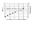
図6に示すように、ピストン本体19の直径をd、遮熱層外周部21bのスロープ長をsとしたときに、ピストン本体19の直径dに対するスロープ長sが占める割合(%)に対して、遮熱層21の遮熱率(%)及び残存膜の増加率(%)をプロットしたものを図7に示す。なお、遮熱層21の遮熱率(%)は、シミュレーション結果に基づいて算出することができる。また、残存膜の増加率(%)は、実機検証結果に基づいて算出することができる。
As shown in FIG. 6, when the diameter of the piston
遮熱層外周部21bの径方向幅を40%より大きくすると、遮熱層全体に占める厚さの薄い領域の割合が高くなり、遮熱性能が低下する虞がある。また、遮熱層外周部21bの径方向幅を5%より小さくすると遮熱性能は高いものの遮熱層が損傷・剥離しやすくなる虞がある。本構成によれば、遮熱層の耐久性と遮熱性能とを両立させることができる。
If the radial width of the heat shield layer outer
<ピストンの製造方法>
次に、本実施形態に係るピストンの製造方法について説明する。
<Manufacturing method of piston>
Next, the manufacturing method of the piston which concerns on this embodiment is demonstrated.
まず、ピストン本体19と遮熱層21を形成するための遮熱材料とを準備する。
First, a heat shield material for forming the
ピストン本体19については、その頂面10’にキャビティ形成用の凹部を形成しておき、脱脂処理により、ピストン本体19の頂面10’に付着している油脂や指紋等の汚れを除去する。
The
また、バインダ材32としての液状シリコーン樹脂と中空粒子31としてのガラスバルーンとを攪拌・混合した遮熱材料を準備する。必要に応じて、増粘剤や希釈溶剤を添加して遮熱材料の粘度を調整する。
In addition, a heat shielding material is prepared by stirring and mixing a liquid silicone resin as the
ピストン本体19と遮熱材料、特にシリコーン樹脂との付着力を高めるべく、ピストン本体19の頂面10’に粗面化処理を施すことが好ましい。粗面化処理としては、例えばサンドブラスト等のブラスト処理を行うことが好ましい。例えば、ブラスト処理は、エアーブラスト装置を使用し、研削材として粒度#30のアルミナを用い、圧力0.39MPa、時間45秒、距離100mmの処理条件で行うことができる。なお、これに限らず、ピストン本体19がAl合金からなる場合、アルマイト処理によってピストン本体19の頂面10’に微小凹凸を形成するようにしてもよい。例えば、アルマイト処理は、シュウ酸浴を用い、浴温20℃、電流密度2A/dm2、時間20分の処理条件で行うことができる。
In order to increase the adhesion between the
しかる後、ピストン本体19の頂面10’に遮熱材料を載せ、ピストン本体19の頂面10’の形状に倣った成形面を有する成形型によって遮熱材料をピストン本体頂面10’に押し付けて頂面10’の全体に拡げる。
Thereafter, a heat shielding material is placed on the top surface 10 'of the
なお、本実施形態においては、スキッシュエリア面12’の遮熱層外周部21bの厚さがピストン本体19頂面径方向内周側から外周側に向かって次第に減少するように成形型の成形面を形成する。そして、遮熱層内周部21aの外周側端部表面が前記遮熱層外周部21bの内周側端部表面から滑らかに接続されるように成形型の成形面を形成する。なお、遮熱層内周部21aの外周側端部表面と前記遮熱層外周部21bの内周側端部表面との接続部は、丸みを帯びた形状としてもよい。
In the present embodiment, the molding surface of the mold is such that the thickness of the outer
次に、ピストン本体19の頂面10’に塗布された遮熱材料に対して、例えば、180℃前後の温度で数時間ないし数十時間の加熱処理を行う。これにより、シリコーン樹脂(バインダ)が硬化して、多数の中空粒子31が密に充填され、それら粒子間がバインダ材32で埋まった遮熱層21が得られる。
Next, the heat shielding material applied to the
なお、本方法によれば、成形中に成形型を加熱することにより、遮熱層21の焼成を同時に行う構成としてもよい。これにより、遮熱層21の製造工程を簡略化することができる。また、遮熱層21の焼成を同時に行う場合には、ピストン本体19を、例えばピストンスカートの内側から水冷又は空冷する等の方法によって冷却する構成とすることができる。これにより、遮熱層21とピストン本体19の頂面10’との密着性を向上させることができる。
In addition, according to this method, it is good also as a structure which bakes the
[第2実施形態]
以下、本発明に係る他の実施形態について詳述する。なお、これらの実施形態の説明において、第1実施形態と同じ部分については同じ符号を付して詳細な説明を省略する。
[Second Embodiment]
Hereinafter, other embodiments according to the present invention will be described in detail. In the description of these embodiments, the same parts as those in the first embodiment are denoted by the same reference numerals, and detailed description thereof is omitted.
<遮熱層>
本実施形態に係る遮熱層21は、第1実施形態の構成に加え、さらに磁性体粒子を含む。
<Heat shield layer>
The
磁性体粒子は具体的には例えば、マグネタイトFe3O4、パーマロイFe−Ni等の微粒子である。これらの磁性体粒子は、微妙な磁場の変化に対して容易に応答し得るため遮熱材料の成形が容易となるとともに、熱伝導率も低いため遮熱層21の優れた遮熱性能を保持することができ、特に、界面活性剤で安定化されたマグネタイトFe3O4の微粒子が好ましい。磁性体粒子の平均粒子径は、バインダ材への均一な分散性を確保する観点から、好ましくは1nm以上100nm以下、より好ましくは1nm以上50nm以下、特に好ましくは1nm以上20nm以下である。
Specifically, the magnetic particles are fine particles such as magnetite Fe 3 O 4 and permalloy Fe—Ni. Since these magnetic particles can easily respond to subtle changes in the magnetic field, the heat shielding material can be easily molded, and the thermal conductivity is low, so that the heat shielding performance of the
<ピストンの製造方法>
バインダ材32としての液状シリコーン樹脂と中空粒子31としてのガラスバルーンに加え、磁性体粒子としてマグネタイト微粒子のヘキサン溶液(平均粒子径10nm)とを攪拌・混合した遮熱材料を準備する。必要に応じて、増粘剤や希釈溶剤を添加して遮熱材料の粘度を調整する。
<Manufacturing method of piston>
In addition to the liquid silicone resin as the
なお、当該遮熱材料中における磁性体粒子の含有量は、好ましくは5質量%以上50質量%以下、より好ましくは10質量%以上45質量%以下、特に好ましくは15質量%以上40質量%以下である。 The content of the magnetic particles in the heat shielding material is preferably 5% by mass to 50% by mass, more preferably 10% by mass to 45% by mass, and particularly preferably 15% by mass to 40% by mass. It is.
しかる後、遮熱材料をピストン本体19の頂面10’にスプレーや刷毛等を用いて塗布する(塗布工程S1)。
Thereafter, the heat shielding material is applied to the top surface 10 'of the
具体的には例えば、塗布工程S1は以下の3つの工程からなる。すなわち、まずピストン本体19の頂面10’のスキッシュエリア面12’を含む頂面10’の外周部のみにマスキングを行い、キャビティ面11’等を含む頂面10’の内周部に必要回数の重ね塗りを行って、後述する調整工程S2において遮熱材料の厚さを調整しない遮熱層内周部21aに該当する部位に遮熱材料を塗布する(先塗布工程S11)。なお、上記マスキングは、マスキングテープ又は、樹脂系のマスキング膜を用いて行うことができる。
Specifically, for example, the coating step S1 includes the following three steps. That is, first, only the outer peripheral portion of the
次に、先塗布工程S11で塗布された遮熱材料に対し、熱風乾燥、赤外線ヒータ等を用いて予備乾燥を行い、遮熱層内周部21aを形成する(乾燥工程S12)。なお、予備乾燥は、後述する調整工程S2において遮熱材料層の形状を保持する観点から、好ましくは150℃以上200℃以下、より好ましくは160℃以上190℃以下、特に好ましくは175℃以上185℃以下で、好ましくは10分以上2時間以内、より好ましくは20分以上1.5時間以内、特に好ましくは30分以上1時間以内行う。
Next, the heat shielding material applied in the previous application step S11 is preliminarily dried using hot air drying, an infrared heater or the like to form the heat shielding layer inner
その後、スキッシュエリア面12’のマスキングを除去し、スキッシュエリア面12’表面を脱脂処理する。そして、後述する調整工程S2において厚さを調整する遮熱層外周部21bに相当する部位に遮熱材料を塗布する(後塗布工程S13)。このとき、頂面10’の外周側の遮熱層外周部21bの厚さを、遮熱層内周部21aの厚さよりも薄くなるように遮熱材料を塗布する。
Thereafter, masking of the squish area surface 12 'is removed, and the surface of the squish area surface 12' is degreased. And a heat-shielding material is apply | coated to the site | part corresponded to the heat-shielding layer outer
そうして、磁石51の磁力を用いて遮熱層外周部21bの遮熱材料の厚さを調整し、傾斜を付ける(調整工程S2)。具体的には例えば、頂面外周側から頂面内周側に向けて磁石を動かし、磁力により遮熱材料を引き上げる。これにより、遮熱層外周部21bのうち、遮熱層内周部21aに近い位置では、遮熱材料の付着量が多くなる一方、外周側の位置では、遮熱材料の付着量が少なくなる。そうして、ピストン本体19頂面径方向内周側から外周側に向かうにつれて次第に厚さが減少するように構成された遮熱層外周部21bが得られる。なお、磁石51の磁界強度は、磁力による遮熱材料の引き上げ速度を制御して遮熱材料の表面をより滑らかに形成する観点から、例えば200〜250kA/mとすることができる。
Then, using the magnetic force of the magnet 51, the thickness of the heat shield material of the heat shield layer outer
なお、磁石を頂面外周側から頂面内周側へ複数回動かすことにより、遮熱層外周部21bは、ピストン本体頂面10’の径方向内周側から外周側に向かって厚さが段差なく連続的に減少するように滑らかに形成することができる。
In addition, by moving the magnet a plurality of times from the top surface outer peripheral side to the top surface inner peripheral side, the thickness of the heat shield layer outer
また、遮熱層外周部21bの内周側端部と遮熱層内周部21aの外周側端部との境界において、磁石を腸満外周側から頂面内周側へ複数回往復動させることにより、両端部表面が滑らかに接続された遮熱層21を得ることができる。
Further, the magnet is reciprocated a plurality of times from the intestinal outer peripheral side to the top inner peripheral side at the boundary between the inner peripheral side end portion of the heat shielding layer outer
最後に、第1実施形態と同様に焼成処理を行い、塗布工程S1において塗布された遮熱材料を硬化させてピストン本体19の頂面10’に遮熱層21を形成する。
Finally, a baking process is performed in the same manner as in the first embodiment, and the heat shielding material applied in the application step S <b> 1 is cured to form the
本発明によれば、遮熱材料の表面に触れることなく遮熱材料の厚さを調整することができる。そうして、複雑な形状を有するピストン本体19の頂面10’に対しても滑らかな表面の遮熱層を形成することができる。
According to the present invention, the thickness of the heat shield material can be adjusted without touching the surface of the heat shield material. As a result, a heat shielding layer having a smooth surface can be formed on the
本構成によると、ヘラや刷毛等で遮熱材料の表面に触れて物理的に遮熱材料な厚さを調整する従来の方法と異なり、遮熱材料の表面に触れることなく遮熱層の外周部と内周部との境界部に該当する箇所の遮熱材料の厚さを調整することができる。そうして、境界部にエッジ等が形成されることなく、境界部の表面を滑らかに接続させることができる。その結果、遮熱層表面に形成される段差を最小限とし、燃焼室内の筒内流動の乱れを抑えて冷却損失を低減させることができる。 According to this configuration, unlike the conventional method of physically adjusting the thickness of the heat shield material by touching the surface of the heat shield material with a spatula or a brush, the outer periphery of the heat shield layer without touching the surface of the heat shield material. It is possible to adjust the thickness of the heat shielding material at a location corresponding to the boundary portion between the portion and the inner peripheral portion. Thus, the surface of the boundary can be smoothly connected without forming an edge or the like at the boundary. As a result, the level difference formed on the surface of the heat shield layer can be minimized, the disturbance of the in-cylinder flow in the combustion chamber can be suppressed, and the cooling loss can be reduced.
また、遮熱層外周部21bの遮熱材料の厚さを段差なく連続的に外周側に向かって減少するように形成することができるので、特にスキッシュエリアでの乱流の発生を効果的に抑制するとともに、スキッシュエリアでノッキングが生じてもクラックの成長を抑制し、遮熱層の損傷・剥離を抑えることができる。
Further, since the thickness of the heat shielding material of the heat shielding layer outer
また、磁力を制御することで、遮熱層の厚さを自在に変更させることができるので、例えば異なる径のピストンであっても、設備を大きく変更させることなく遮熱層を形成することができる。 In addition, since the thickness of the heat shield layer can be freely changed by controlling the magnetic force, it is possible to form the heat shield layer without greatly changing the equipment even for pistons with different diameters, for example. it can.
また、上述のごとく、遮熱層の厚さを所定の厚さに保持したい部分の磁性材料については、先塗布工程S11で塗布した後、前記乾燥工程S12により予め乾燥させて硬化させておくことで、後の調整工程S2において遮熱材料に磁力を与えたときに、遮熱層の厚さを調整したい部分のみ調整することができる。 In addition, as described above, the magnetic material of the portion where it is desired to keep the thickness of the heat shield layer at a predetermined thickness is applied in the first application step S11 and then dried and cured in advance in the drying step S12. Thus, when a magnetic force is applied to the heat shield material in the subsequent adjustment step S2, only the portion where the thickness of the heat shield layer is desired to be adjusted can be adjusted.
なお、後塗布工程S13及び調整工程S2を複数回繰り返して行う構成としてもよい。 The post-coating step S13 and the adjusting step S2 may be repeated a plurality of times.
本構成によれば、遮熱層の厚さを調整したい部分の遮熱材料を複数回に分けて塗布し、その厚さを調整することで、微細な厚さの調整を行うことができ、遮熱層の表面をより滑らかに形成することができる。また、径が大きなピストンにおいても表面が滑らかな遮熱層を効果的に形成することができる。 According to this configuration, by applying the heat shielding material of the portion where the thickness of the heat shielding layer is desired to be divided into a plurality of times and adjusting the thickness, the fine thickness can be adjusted, The surface of the heat shield layer can be formed more smoothly. In addition, a heat shield layer having a smooth surface can be effectively formed even in a piston having a large diameter.
本発明は、スキッシュエリア面に遮熱層を形成しつつ、ノッキングによる当該遮熱層の損傷・剥離を抑えるとともに、スキッシュエリアにおいて乱流の発生を防止し冷却損失を低減させることができるので、極めて有用である。 The present invention suppresses damage and separation of the heat shield layer due to knocking while forming a heat shield layer on the surface of the squish area, and also prevents turbulent flow in the squish area and reduces cooling loss. Very useful.
1 ピストン
10 (ピストンの)冠面
10’ (ピストン本体の)頂面
11 キャビティ部
11’ キャビティ面
12,12a,12b,12c,12d スキッシュエリア部
12’,12a’,12b’,12c’,12d’ スキッシュエリア面
19 ピストン本体
21 遮熱層
21a 遮熱層内周部(内周部)
21b 遮熱層外周部(外周部)
31 中空粒子
32 バインダ材(バインダ)
E エンジン
DESCRIPTION OF SYMBOLS 1
21b Heat shield layer outer periphery (outer periphery)
31
E engine
Claims (9)
前記ピストン本体の頂面に形成された遮熱層と、
を備えた内燃機関用ピストンであって、
前記遮熱層は、
前記ピストン本体の頂面の少なくとも前記スキッシュエリア面を含む外周側に形成され、該ピストン本体頂面の径方向内周側から外周側に向かって厚さが次第に減少している外周部と、
前記ピストン本体の頂面において前記外周部よりも内周側に形成され、外周側端部表面が前記外周部の内周側端部表面から滑らかに接続されるように形成された内周部と、を備えた
ことを特徴とする内燃機関用ピストン。 A piston body having a squish area surface that forms a squish area of the combustion chamber of the internal combustion engine on the outer peripheral side of the top surface;
A heat insulating layer formed on the top surface of the piston body;
A piston for an internal combustion engine comprising:
The thermal barrier layer is
An outer peripheral portion that is formed on the outer peripheral side including at least the squish area surface of the top surface of the piston main body, and whose thickness gradually decreases from the radially inner peripheral side to the outer peripheral side of the piston main body top surface;
An inner peripheral part formed on the inner peripheral side of the outer peripheral part on the top surface of the piston main body, the outer peripheral side end part surface being smoothly connected from the inner peripheral side end part surface of the outer peripheral part; A piston for an internal combustion engine, comprising:
前記遮熱層の外周部は、前記ピストン本体頂面の径方向内周側から外周側に向かって厚さが段差なく連続的に減少するように形成されていることを特徴とする内燃機関用ピストン。 In claim 1,
The outer peripheral portion of the heat shield layer is formed so that the thickness continuously decreases without a step from the radially inner peripheral side to the outer peripheral side of the top surface of the piston body. piston.
前記遮熱層の内周部及び外周部により、前記ピストン本体頂面の全面が覆われていることを特徴とする内燃機関用ピストン。 In claim 1 or claim 2,
A piston for an internal combustion engine, characterized in that the entire top surface of the piston body is covered with an inner peripheral portion and an outer peripheral portion of the heat shield layer.
前記遮熱層の外周部の外周側端部厚さは、該外周部の内周側端部厚さの20%以上60%以下であることを特徴とする内燃機関用ピストン。 In any one of Claim 1 thru | or 3,
A piston for an internal combustion engine, wherein an outer peripheral end thickness of an outer peripheral portion of the heat shield layer is 20% or more and 60% or less of an inner peripheral end portion thickness of the outer peripheral portion.
前記遮熱層の外周部の径方向幅は、前記ピストン本体頂面外径の5%以上30%以内であることを特徴とする内燃機関用ピストン。 In any one of Claims 1 thru | or 4,
A piston for an internal combustion engine, wherein a radial width of an outer peripheral portion of the heat shield layer is 5% or more and 30% or less of an outer diameter of a top surface of the piston body.
前記遮熱層の内周部の厚さは一定であることを特徴とする内燃機関用ピストン。 In any one of Claims 1 thru | or 5,
A piston for an internal combustion engine, wherein a thickness of an inner peripheral portion of the heat shield layer is constant.
前記遮熱層は、
多数の中空粒子と、
前記中空粒子を前記ピストン本体の頂面に保持するとともに、前記中空粒子間を埋めて前記遮熱層の母材を形成するバインダと、を含む
ことを特徴とする内燃機関用ピストン。 In any one of Claims 1 thru | or 6,
The thermal barrier layer is
Many hollow particles,
A piston for an internal combustion engine, comprising: a binder that holds the hollow particles on a top surface of the piston body and fills a space between the hollow particles to form a base material of the heat shield layer.
前記バインダは、シリコーン系樹脂であることを特徴とする内燃機関用ピストン。 In claim 7,
The piston for an internal combustion engine, wherein the binder is a silicone resin.
前記中空粒子は、ガラスバルーンであることを特徴とする内燃機関用ピストン。 In claim 7 or claim 8,
The internal combustion engine piston, wherein the hollow particles are glass balloons.
Priority Applications (1)
| Application Number | Priority Date | Filing Date | Title |
|---|---|---|---|
| JP2016096384A JP2017203437A (en) | 2016-05-12 | 2016-05-12 | Piston for internal combustion engine |
Applications Claiming Priority (1)
| Application Number | Priority Date | Filing Date | Title |
|---|---|---|---|
| JP2016096384A JP2017203437A (en) | 2016-05-12 | 2016-05-12 | Piston for internal combustion engine |
Publications (1)
| Publication Number | Publication Date |
|---|---|
| JP2017203437A true JP2017203437A (en) | 2017-11-16 |
Family
ID=60322154
Family Applications (1)
| Application Number | Title | Priority Date | Filing Date |
|---|---|---|---|
| JP2016096384A Pending JP2017203437A (en) | 2016-05-12 | 2016-05-12 | Piston for internal combustion engine |
Country Status (1)
| Country | Link |
|---|---|
| JP (1) | JP2017203437A (en) |
Citations (4)
| Publication number | Priority date | Publication date | Assignee | Title |
|---|---|---|---|---|
| JPS5645134U (en) * | 1979-09-17 | 1981-04-23 | ||
| JPH0233412A (en) * | 1988-07-21 | 1990-02-02 | Isuzu Motors Ltd | Structure of adiabatic engine |
| US20130104846A1 (en) * | 2011-08-12 | 2013-05-02 | Mcalister Technologies, Llc | Combustion chamber inserts and associated methods of use and manufacture |
| JP2016056903A (en) * | 2014-09-11 | 2016-04-21 | マツダ株式会社 | Heat insulation layer |
-
2016
- 2016-05-12 JP JP2016096384A patent/JP2017203437A/en active Pending
Patent Citations (4)
| Publication number | Priority date | Publication date | Assignee | Title |
|---|---|---|---|---|
| JPS5645134U (en) * | 1979-09-17 | 1981-04-23 | ||
| JPH0233412A (en) * | 1988-07-21 | 1990-02-02 | Isuzu Motors Ltd | Structure of adiabatic engine |
| US20130104846A1 (en) * | 2011-08-12 | 2013-05-02 | Mcalister Technologies, Llc | Combustion chamber inserts and associated methods of use and manufacture |
| JP2016056903A (en) * | 2014-09-11 | 2016-04-21 | マツダ株式会社 | Heat insulation layer |
Similar Documents
| Publication | Publication Date | Title |
|---|---|---|
| JP6281551B2 (en) | Engine combustion chamber insulation structure | |
| US10161297B2 (en) | Heat-insulating structure of member facing engine combustion chamber, and process for producing same | |
| JP6321934B2 (en) | Method for manufacturing a heat insulating layer on a member surface facing an engine combustion chamber | |
| EP2679791A1 (en) | Engine and piston | |
| JP6170029B2 (en) | Method for forming a thermal barrier film | |
| JP6178303B2 (en) | Internal combustion engine | |
| JP6326880B2 (en) | Formation method of heat insulation layer | |
| JP6451581B2 (en) | Engine combustion chamber insulation structure | |
| JP6217569B2 (en) | Thermal insulation layer | |
| JP5998696B2 (en) | Engine combustion chamber insulation structure | |
| JP6380457B2 (en) | Method for forming a thermal barrier layer of a piston for an internal combustion engine | |
| JP5974701B2 (en) | Engine combustion chamber structure | |
| CN106817906B (en) | The manufacturing method of piston for engine | |
| JP6036368B2 (en) | Thermal insulation structure for engine combustion chamber and method for manufacturing the same | |
| JP2017115781A (en) | Internal combustion engine piston, internal combustion engine and process of manufacture of internal combustion engine piston | |
| JP2017203437A (en) | Piston for internal combustion engine | |
| JP2014040819A (en) | Method for manufacturing piston for engine | |
| JP2017001235A (en) | Thermal insulation structure | |
| JP2017067012A (en) | Engine heat insulation structure | |
| JP2018145957A (en) | Piston for internal combustion engine | |
| JPS6014901B2 (en) | Piston manufacturing method | |
| JP2014040817A (en) | Heat insulation structure of engine combustion chamber component, and method for manufacturing the same | |
| JP5971372B1 (en) | Engine manufacturing method | |
| JP6090282B2 (en) | Method for forming a heat insulating layer on the inner peripheral surface of a cylindrical hole | |
| JP7129759B2 (en) | Thermal barrier coating layer forming method, and engine part provided with thermal barrier coating layer |
Legal Events
| Date | Code | Title | Description |
|---|---|---|---|
| A977 | Report on retrieval |
Free format text: JAPANESE INTERMEDIATE CODE: A971007 Effective date: 20180215 |
|
| A131 | Notification of reasons for refusal |
Free format text: JAPANESE INTERMEDIATE CODE: A131 Effective date: 20180327 |
|
| A521 | Request for written amendment filed |
Free format text: JAPANESE INTERMEDIATE CODE: A523 Effective date: 20180525 |
|
| A02 | Decision of refusal |
Free format text: JAPANESE INTERMEDIATE CODE: A02 Effective date: 20181016 |