JP2017203386A - piston - Google Patents
piston Download PDFInfo
- Publication number
- JP2017203386A JP2017203386A JP2016093949A JP2016093949A JP2017203386A JP 2017203386 A JP2017203386 A JP 2017203386A JP 2016093949 A JP2016093949 A JP 2016093949A JP 2016093949 A JP2016093949 A JP 2016093949A JP 2017203386 A JP2017203386 A JP 2017203386A
- Authority
- JP
- Japan
- Prior art keywords
- piston
- end surface
- outer periphery
- center
- face
- Prior art date
- Legal status (The legal status is an assumption and is not a legal conclusion. Google has not performed a legal analysis and makes no representation as to the accuracy of the status listed.)
- Granted
Links
Images


Abstract
Description
本発明はピストンに関する。 The present invention relates to a piston.
内燃機関(エンジン)のピストンの外周面には溝が形成されており、当該溝にピストンリングが装着される。ピストンのトップリング溝と頂面との間の領域であるトップランドにおいては、ピストンの外周面とシリンダの内周面との間隙(クレビス)に油膜が形成される(例えば特許文献1)。 A groove is formed on the outer peripheral surface of the piston of the internal combustion engine (engine), and a piston ring is attached to the groove. In the top land, which is a region between the top ring groove and the top surface of the piston, an oil film is formed in a gap (clevis) between the outer peripheral surface of the piston and the inner peripheral surface of the cylinder (for example, Patent Document 1).
しかし適正な大きさのクレビスが確保されない場合、油膜切れが発生し、ピストンとシリンダとの焼き付きが生じる。また、ピストンを加工する際、切削量が多くなると、生産性が低下する。 However, when a clevis of an appropriate size is not secured, the oil film is cut and seizure occurs between the piston and the cylinder. Further, when machining the piston, if the amount of cutting increases, productivity decreases.
本発明は、上記課題に鑑み、生産性が高く、かつ油膜切れを抑制することが可能なピストンを提供することを目的とする。 In view of the above problems, an object of the present invention is to provide a piston that has high productivity and can suppress oil film breakage.
上記目的は、トップランドの下端面の外周は真円形状であり、前記トップランドの上端面の外周はスラスト側から反スラスト側にかけて長軸を有する楕円形状であり、前記上端面の楕円形状の中心は、前記下端面の真円形状の中心よりスラスト側に位置し、前記上端面の外周は前記下端面の外周より内側に位置するピストンによって達成できる。 The above-mentioned object is that the outer periphery of the lower end surface of the top land is a perfect circle shape, the outer periphery of the upper end surface of the top land is an elliptical shape having a long axis from the thrust side to the anti-thrust side, and the elliptical shape of the upper end surface is The center can be achieved by a piston located on the thrust side from the center of the perfect circle shape of the lower end surface, and the outer periphery of the upper end surface can be achieved by a piston located inside the outer periphery of the lower end surface.
生産性が高く、かつ油膜切れを抑制することが可能なピストンを提供できる。 It is possible to provide a piston that is high in productivity and can suppress oil film breakage.
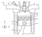
以下、本発明の好ましい実施例について、図面を参照しつつ説明する。図1はエンジン100の概略図である。図1に示すように、エンジン100は、シリンダ10、吸気管12、排気管14、点火プラグ16、燃料噴射弁18、ピストン20、およびコンロッド22を備える。
Hereinafter, preferred embodiments of the present invention will be described with reference to the drawings. FIG. 1 is a schematic diagram of the
シリンダ10には、吸気管12、排気管14、点火プラグ16、および燃料噴射弁18が設けられている。燃料噴射弁18は吸気管12に設けられており、燃料を噴射する。吸気管12からシリンダ10内に燃料と空気との混合気が導入される。点火プラグ16により混合気が燃焼する。混合気の燃焼により、ピストン20はシリンダ10内を上下に摺動する。燃焼後の排気ガスはシリンダ10から排気管14へと排出される。
The
ピストン20のピストン本体21はピン24によりコンロッド22の一端に連結されており、コンロッド22の他端はクランクシャフト(不図示)に連結されている。ピストン本体21の外周面には溝が設けられており、当該溝にはピストンリング26が装着される。ピストン本体21の外周面とシリンダ10の内壁10aとの間には間隙(クレビス11)が形成される。図1のX方向はピン24の挿入方向、Z方向はピストン20の摺動方向、Y方向はXおよびZ方向に直交する方向である。
The
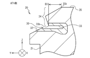
図2はピストン20を例示する平面図であり、ピストン20を摺動方向(Z方向)から見ている。図2の−Y方向をスラスト(Th)側、+Y方向を反スラスト(ATh)側、+X方向をRr側、−X方向をFr側とする。図3はスラスト(Th)側を拡大した断面図である。図4は反スラスト(ATh)側を拡大した断面図である。図5はFr側を拡大した断面図である。
FIG. 2 is a plan view illustrating the
図3から図5に示すように、ピストン本体21の外周面にはピストンリング26が装着される溝30が設けられている。溝30は複数の溝のうち、最も上側(Z側)に設けられている。溝30の内壁部分には耐摩環32が形成されている。耐摩環32は例えば二レジスト鋳鉄など強度の高い材料で形成されている。ピストン本体21の耐摩環32以外の部分は、例えばアルミニウム合金などの金属で形成されている。トップランド34はピストン20の溝30から上面までの領域である。
As shown in FIGS. 3 to 5, a
図2に示すように、トップランド34の下端面33(耐摩環32の表面の1つ)の外周は、中心をO1とする真円形状である。線23はX方向に延び、中心O1を通る仮想的な線である。線25はY方向に延び、中心O1を通る仮想的な線である。トップランド34の上端面35の外周は、中心をO2とする楕円形状である。線27はX方向に延び、中心O2を通る仮想的な線である。X方向は上端面35の短軸の方向、Y方向は上端面35の長軸の方向である。
As shown in FIG. 2, the outer periphery of the
図2に示すように、Y方向において、中心O2は中心O1よりもTh側に位置する。中心O1と中心O2とが距離D1だけ離間している。図2および図5に示す、Fr側における上端面35の端部35cと、下端面33の端部33cとのX方向における距離はD4である。Rr側の端部35dと端部33dとの距離はD4と同じである。
As shown in FIG. 2, in the Y direction, the center O2 is located on the Th side with respect to the center O1. The center O1 and the center O2 are separated by a distance D1. The distance in the X direction between the
本実施例によれば、トップランド34の上端面35の外周は楕円形状を有し、中心O2は下端面33の中心O1よりTh側に位置している。このため、ATh側における上端面35の端部35bと下端面33の端部33bとの距離D3が、Th側における端部35aと端部33aとの距離D2より大きくなる。つまりATh側において、ピストン20とシリンダ10との間隔(クレビス11)が大きくなる。この結果、ATh側において油膜切れ、およびピストン20とシリンダ10との焼き付きを抑制することができる。
According to the present embodiment, the outer periphery of the
またTh側、Fr側およびRr側においても、トップランド34の上端面35の外周は下端面33の外周より内側に位置する。すなわちクレビス11が確保されるため、油膜切れが抑制され、ピストン20とシリンダ10との焼き付きを抑制することができる。
Further, on the Th side, the Fr side, and the Rr side, the outer periphery of the
下端面33の外周は真円形状を有する。例えば楕円形状とする場合に比べてピストン20を形成する際の切削量が少なくなる。このため、ピストン20の生産性が向上する。特に下端面33は耐摩環32に含まれるため、二レジスト鋳鉄など切削性の低い材料で形成される。下端面33の外周を真円形状とすることで、切削量が少なくなり、生産性が向上する。また、楕円形状に加工する場合、形状に起因して切削抵抗が変動するため、生産性が悪化する。真円形状とすることで、切削抵抗の変動が抑制され、生産性が向上する。
The outer periphery of the
ピストン本体21および耐摩環32の材料は上記のものに限定されない。耐摩環32は、高い負荷に耐えることができるように、ピストン本体21の他の部分よりも高い強度の材料で形成されることが好ましい。耐摩環32は、ピストン20の溝の全てに設けられてもよいし、一部の溝に設けられてもよい。耐摩環32は、少なくともトップリングの装着される溝に設けられることが好ましい。なお、ピストン20に耐摩環32が設けられなくてもよい。つまり、ピストン20のピストンリング26が装着される部分が、ピストン20の他の部分と同じ材料で形成されてもよい。トップランド34の下端面33の外周を真円形状とすることで、切削抵抗の変動が抑制され、生産性が向上する。
The material of the
なお、下端面33の外周は幾何学的に正確な真円でなくてもよく、例えば上端面35の外周より真円に近ければよい。上端面35の外周は幾何学的に正確な楕円でなくてもよい。
Note that the outer periphery of the
以上本発明の好ましい実施形態について詳述したが、本発明は係る特定の実施形態に限定されるものではなく、特許請求の範囲に記載された本発明の要旨の範囲内において、種々の変形・変更が可能である。 Although the preferred embodiments of the present invention have been described in detail above, the present invention is not limited to the specific embodiments, and various modifications and changes can be made within the scope of the gist of the present invention described in the claims. It can be changed.
10 シリンダ
11 クレビス
20 ピストン
21 ピストン本体
24 ピン
26 ピストンリング
30 溝
32 耐摩環
33 下端面
33a〜33d、35a〜35d 端部
34 トップランド
35 上端面
100 エンジン
O1、O2 中心
DESCRIPTION OF
Claims (1)
前記上端面の楕円形状の中心は、前記下端面の真円形状の中心よりスラスト側に位置し、
前記上端面の外周は前記下端面の外周より内側に位置するピストン。
The outer periphery of the lower end surface of the top land has a perfect circle shape, and the outer periphery of the upper end surface of the top land has an elliptical shape having a major axis from the thrust side to the anti-thrust side,
The center of the elliptical shape of the upper end surface is located on the thrust side from the center of the perfect circular shape of the lower end surface,
The outer periphery of the upper end surface is a piston located inside the outer periphery of the lower end surface.
Priority Applications (1)
| Application Number | Priority Date | Filing Date | Title |
|---|---|---|---|
| JP2016093949A JP6528720B2 (en) | 2016-05-09 | 2016-05-09 | piston |
Applications Claiming Priority (1)
| Application Number | Priority Date | Filing Date | Title |
|---|---|---|---|
| JP2016093949A JP6528720B2 (en) | 2016-05-09 | 2016-05-09 | piston |
Publications (2)
| Publication Number | Publication Date |
|---|---|
| JP2017203386A true JP2017203386A (en) | 2017-11-16 |
| JP6528720B2 JP6528720B2 (en) | 2019-06-12 |
Family
ID=60323144
Family Applications (1)
| Application Number | Title | Priority Date | Filing Date |
|---|---|---|---|
| JP2016093949A Expired - Fee Related JP6528720B2 (en) | 2016-05-09 | 2016-05-09 | piston |
Country Status (1)
| Country | Link |
|---|---|
| JP (1) | JP6528720B2 (en) |
Cited By (1)
| Publication number | Priority date | Publication date | Assignee | Title |
|---|---|---|---|---|
| US20180030921A1 (en) * | 2016-07-29 | 2018-02-01 | Caterpillar Inc. | Piston top land structure |
-
2016
- 2016-05-09 JP JP2016093949A patent/JP6528720B2/en not_active Expired - Fee Related
Cited By (2)
| Publication number | Priority date | Publication date | Assignee | Title |
|---|---|---|---|---|
| US20180030921A1 (en) * | 2016-07-29 | 2018-02-01 | Caterpillar Inc. | Piston top land structure |
| US10030604B2 (en) * | 2016-07-29 | 2018-07-24 | Caterpillar Inc. | Piston top land structure |
Also Published As
| Publication number | Publication date |
|---|---|
| JP6528720B2 (en) | 2019-06-12 |
Similar Documents
| Publication | Publication Date | Title |
|---|---|---|
| US8365696B2 (en) | Piston device for internal combustion engines | |
| JP5893946B2 (en) | engine | |
| JP6734931B2 (en) | Internal combustion engine | |
| JP2010164012A (en) | Piston for internal combustion engine | |
| JP6528720B2 (en) | piston | |
| US11371610B2 (en) | Flutter-suppression piston ring | |
| KR102077376B1 (en) | A four-stroke internal combustion engine and a piston therefor | |
| WO2019203358A1 (en) | Piston ring | |
| JP2015129463A (en) | Internal combustion engine piston | |
| US10323602B2 (en) | Piston bowl rim with fatigue resistance | |
| JP6374269B2 (en) | Piston pin lubrication structure | |
| WO2017130457A1 (en) | Connecting rod and crosshead-type engine provided with same | |
| JP2016118276A (en) | Combination oil ring | |
| US20240159200A1 (en) | Internal combustion engine | |
| JP6914291B2 (en) | Internal combustion engine cylinder | |
| JP5267936B2 (en) | Piston of internal combustion engine | |
| JP6890149B2 (en) | Internal combustion engine piston | |
| KR102429575B1 (en) | Piston | |
| JP2017218933A (en) | Lubrication structure of piston pin | |
| JP6393823B1 (en) | Gas engine combustion chamber structure | |
| JP3206675U (en) | Piston member and internal combustion engine provided with the same | |
| JP2021102928A (en) | piston | |
| JP6048179B2 (en) | Piston and internal combustion engine | |
| WO2017115711A1 (en) | Piston for internal combustion engine | |
| JP2014009620A (en) | Piston ring for internal combustion engine |
Legal Events
| Date | Code | Title | Description |
|---|---|---|---|
| A621 | Written request for application examination |
Free format text: JAPANESE INTERMEDIATE CODE: A621 Effective date: 20180724 |
|
| TRDD | Decision of grant or rejection written | ||
| A977 | Report on retrieval |
Free format text: JAPANESE INTERMEDIATE CODE: A971007 Effective date: 20190410 |
|
| A01 | Written decision to grant a patent or to grant a registration (utility model) |
Free format text: JAPANESE INTERMEDIATE CODE: A01 Effective date: 20190416 |
|
| A61 | First payment of annual fees (during grant procedure) |
Free format text: JAPANESE INTERMEDIATE CODE: A61 Effective date: 20190429 |
|
| R151 | Written notification of patent or utility model registration |
Ref document number: 6528720 Country of ref document: JP Free format text: JAPANESE INTERMEDIATE CODE: R151 |
|
| LAPS | Cancellation because of no payment of annual fees |