JP2017201092A - Repair method of building structure and temporary window screen - Google Patents
Repair method of building structure and temporary window screen Download PDFInfo
- Publication number
- JP2017201092A JP2017201092A JP2016092768A JP2016092768A JP2017201092A JP 2017201092 A JP2017201092 A JP 2017201092A JP 2016092768 A JP2016092768 A JP 2016092768A JP 2016092768 A JP2016092768 A JP 2016092768A JP 2017201092 A JP2017201092 A JP 2017201092A
- Authority
- JP
- Japan
- Prior art keywords
- screen door
- temporary
- window
- door body
- frame
- Prior art date
- Legal status (The legal status is an assumption and is not a legal conclusion. Google has not performed a legal analysis and makes no representation as to the accuracy of the status listed.)
- Pending
Links
Images


Landscapes
- Working Measures On Existing Buildindgs (AREA)
Abstract
Description
本発明は、建造物の基本性能を維持するために定期的に実施される大規模修繕工事等の建造物の修繕工事方法及びその建造物の修繕工事の際に使用する仮網戸に関する。 The present invention relates to a method for repairing a building such as a large-scale repair work that is periodically performed to maintain the basic performance of the building, and a temporary screen used for the repair work of the building.
従来から、マンション等の集合住宅の定期的なメンテナンスや老朽化対策のために、大規模修繕工事を行うことが知られている。大規模修繕工事の中には、様々な工事が含まれており、足場仮設工事、下地補修工事、シーリング工事、高圧水洗浄工事、塗装工事等の各種工事が順次行われることが一般的である。 Conventionally, it is known to perform large-scale repair work for periodic maintenance of apartment houses such as apartments and countermeasures against aging. The large-scale repair work includes various works, and it is common for various works such as temporary scaffolding work, foundation repair work, sealing work, high-pressure water washing work, and painting work to be carried out in sequence. .
例えば、特許文献1では、様々な模様を立体的に表現することができ、大規模修繕工事等にも利用される建造物外壁の塗装方法に関する技術が開示されている。
また、特許文献2では、アルカリ性洗浄水を用いた外壁洗浄、あるいは、酸性洗浄剤を用いて外壁の洗浄を行う際における酸性洗浄剤を洗い流す手段として適用することができ、大規模修繕工事等にも利用される建物外壁の洗浄方法に関する技術が開示されている。
For example,
Moreover, in patent document 2, it can apply as a means to wash away the outer wall washing | cleaning using alkaline washing water, or the acidic cleaning agent at the time of washing | cleaning an outer wall using an acidic cleaning agent, for large-scale repair construction etc. A technique relating to a method for cleaning a building outer wall that is also used is disclosed.
しかしながら、特許文献1や特許文献2に示すような大規模修繕工事が始まると、工事期間中は工事を進捗させるために居住者は種々の制限を受けることになり、それが居住者にとっては多大なストレスになっていた。
例えば、大規模修繕工事においては、窓に取り付けていた網戸は取り外さなくてはいけないので、各居住者は自ら網戸を取外し、その取外した網戸を室内等で各自保管する必要がある。さらに、網戸を取り外した後は、窓を閉めて施錠をし、カーテンを閉めて各自プライバシーを守る必要があるので、室内に入射する日光が遮られると共に、室内の風通しも悪くなる。
そのため、居住者にとっては、室内が暑くなって体調不良を起こしたり、換気をすると外から蚊等の虫や異物が入ってきたりする等の不都合があった。また、窓を閉め切っているため、部屋の湿度が高くなり、カビが生える等の不都合もあった。さらに、普段は自由に出入りできていたバルコニーにも、工事期間中は自由に出入りできなくなり、洗濯等の日常生活にも不都合を生じていた。
以前から上記のようなことに対する苦情が居住者から多数出ており、その解消策が求められてきているが、工事作業者としても、居住者を説得して我慢してもらう以外には解決方法はなく、大規模修繕工事の期間中、その建造物内で生活をする居住者は、安全で快適な生活を送ることができなかった。
However, when a large-scale repair work as shown in
For example, in large-scale repair work, the screen door attached to the window must be removed, so each resident needs to remove the screen door himself and store the removed screen door indoors. Further, after the screen door is removed, it is necessary to close and lock the window and close the curtain to protect the privacy of each person, so that the sunlight incident on the room is blocked and the ventilation of the room is deteriorated.
For this reason, there are inconveniences for residents, such as the indoors become hot and poor physical condition, and when ventilation is performed, insects such as mosquitoes and foreign substances enter from outside. In addition, since the windows are closed, there is a disadvantage that the humidity of the room becomes high and mold grows. In addition, the balcony, which was normally open and closed, was not freely accessible during the construction period, causing inconvenience in daily life such as laundry.
There have been many complaints about the above from residents, and there are calls for solutions. However, as a construction worker, there is a solution other than convincing the residents and putting them up. No, residents who lived in the building during the large-scale repair work were unable to live a safe and comfortable life.
そこで、本発明は、上記の課題に鑑みてなされたものであり、本発明の目的は、大規模修繕工事等の建造物の修繕工事の際に、工事期間中であっても居住者が安全で快適な生活環境を保持することができる建造物の修繕工事方法及びその建造物の修繕工事の際に使用することができる仮網戸を提供することにある。 Therefore, the present invention has been made in view of the above problems, and the object of the present invention is to ensure that a resident is safe even during a construction period during a construction repair work such as a large-scale repair work. It is another object of the present invention to provide a method for repairing a building that can maintain a comfortable living environment and a temporary screen door that can be used for the repair of the building.
前記課題は、本発明の建造物の修繕工事方法によれば、建造物の修繕工事方法において、前記建造物の室内に備えられた窓の一部を開放して前記室内を通気可能状態とし、前記窓を開放した部分の前記窓よりも室内側に仮網戸を設置して通気領域を前記仮網戸で覆うこと、により解決される。
また、前記仮網戸は、上下に伸縮可能な構造であって、前記室内の窓額縁に前記仮網戸の上部及び下部を当接させて固定すること、が好適である。
According to the method for repairing a building of the present invention, the subject is a method for repairing a building, wherein a part of a window provided in the room of the building is opened to allow the room to be ventilated. The problem is solved by installing a temporary screen door on the indoor side of the portion where the window is opened and covering the ventilation area with the temporary screen door.
Further, the temporary screen has a structure that can be vertically expanded and contracted, and it is preferable that the upper and lower portions of the temporary screen door are brought into contact with and fixed to the window frame in the room.
このように、本発明では、大規模修繕工事等の建造物の修繕工事期間中、室内に備えられた窓の一部を開放して通気領域を確保し、その通気領域に仮網戸を設置することにより、風通しが良くなり室内を効率良く換気することができるうえ、虫や異物等の外からの侵入を好適に防止することができる。そのため、居住者は、工事期間中であっても安全で快適な生活環境を保持することができる。
特に、仮網戸を上下に伸縮可能な構造とし、窓額縁に仮網戸の上部及び下部を当接させて固定することにより、種々の窓サイズに対応可能となるうえ、わざわざ窓のサッシレールに嵌め込む必要もなく上下の窓額縁に当接させて固定するだけで済むため、簡単に設置することができる。また、仮網戸は、サッシレール上の窓の移動領域とは異なる領域に設置することになるため、仮網戸を設置した状態まま、窓を全開にしてバルコニーに自由に出入りすることができたり、窓を閉めて施錠したりすることもできる。
As described above, in the present invention, during the repair work of a building such as a large-scale repair work, a part of the windows provided in the room is opened to secure a ventilation area, and a temporary screen door is installed in the ventilation area. As a result, ventilation is improved and the room can be efficiently ventilated, and insects and foreign substances can be suitably prevented from entering from the outside. Therefore, the resident can maintain a safe and comfortable living environment even during the construction period.
In particular, the temporary screen has a structure that can be expanded and contracted vertically, and the upper and lower portions of the temporary screen door are brought into contact with and fixed to the window frame, so that various window sizes can be accommodated, and it is purposely fitted to the window sash rail. Since there is no need to insert it, it is only necessary to contact and fix the upper and lower window frame, so that it can be easily installed. In addition, the temporary screen door will be installed in an area different from the moving area of the window on the sash rail, so you can freely enter and exit the balcony with the window fully open with the temporary screen door installed, The window can be closed and locked.
また、前記課題は、本発明の仮網戸によれば、建造物の室内に備えられた窓の一部を開放した部分の前記窓よりも室内側に設置する仮網戸であって、左右一対の縦枠と上下一対の横枠とからなる枠体に網を張設して成る第一網戸体と、前記第一網戸体を上下に摺動可能に保持するものであって、左右一対の縦枠と上下一対の横枠とからなる枠体に網を張設して成る第二網戸体と、を備えたこと、により解決される。
また、前記第二網戸体の前記縦枠の内側に摺動溝を備え、前記第一網戸体の前記縦枠の外側を前記摺動溝に対向するように摺動可能に組み合わせたこと、が好適である。
また、前記第一網戸体又は前記第二網戸体の前記横枠の外側部分に緩衝部材又は滑り止め部材を備えたこと、が好適である。
また、前記第一網戸体と前記第二網戸体との摺動箇所に摩擦軽減部材を備えたこと、が好適である。
また、前記第一網戸体又は前記第二網戸体の前記横枠の外側部分に前記第一網戸体又は前記第二網戸体を前記仮網戸の中央方向に弾性的に付勢する付勢手段を備えたこと、が好適である。
また、前記第一網戸体又は前記第二網戸体に落下防止手段を備えたこと、が好適である。
In addition, according to the temporary screen door of the present invention, the subject is a temporary screen door that is installed on the indoor side of the window of a part of the window provided in the interior of the building, and is a pair of left and right windows. A first screen door formed by stretching a net on a frame made up of a vertical frame and a pair of upper and lower horizontal frames, and holding the first screen door slidably up and down, This is solved by including a second screen door body formed by stretching a net on a frame body including a frame and a pair of upper and lower horizontal frames.
In addition, a sliding groove is provided on the inner side of the vertical frame of the second screen door body, and the outer side of the vertical frame of the first screen door body is slidably combined so as to face the sliding groove. Is preferred.
Further, it is preferable that a buffer member or a non-slip member is provided on an outer portion of the horizontal frame of the first screen door body or the second screen door body.
In addition, it is preferable that a friction reducing member is provided at a sliding portion between the first screen door body and the second screen door body.
Further, an urging means for elastically urging the first screen door or the second screen door toward the center of the temporary screen on the outer part of the horizontal frame of the first screen door or the second screen door. It is suitable to have provided.
In addition, it is preferable that the first screen door body or the second screen door body is provided with a fall prevention means.
このように、第一網戸体と、その第一網戸体を上下に摺動可能に保持する第二網戸体の2つの網戸体から仮網戸を構成することにより、仮網戸全体が上下に伸縮自在となり、高さ寸法の変更が可能となる。そのため、建造物の修繕工事において仮網戸を窓に設置する際、種々の窓サイズにも対応可能となり、簡単に設置することができる。
特に、第二網戸体の縦枠の内側に摺動溝を形成し、第一網戸体の縦枠の外側をその摺動溝に対向するように摺動可能に組み合わることにより、部品点数が増えたり、複雑な構成にしたりすることなく、好適に仮網戸全体を上下に伸縮自在として高さ寸法の変更が可能となる。
また、第一網戸体又は第二網戸体の横枠の外側部分、具体的には、仮網戸を設置したときに上下の窓額縁に当接する箇所に、摩擦係数の高いゴムやクッションスポンジ等の緩衝部材や滑り止め部材を備えたことにより、仮網戸の設置が容易になると共に、窓額縁を傷付けることなく保護することができ、設置した仮網戸を安定して保持することができる。
また、第一網戸体と第二網戸体との摺動箇所に摺動を補助するブラシ等の摩擦軽減部材を備えることにより、第一網戸体又は第二網戸体の上下の伸縮がよりスムーズになる。
また、第一網戸体又は第二網戸体の前記横枠の外側部分、具体的には、仮網戸を設置したときに上下の窓額縁に当接する箇所に、前記第一網戸体又は前記第二網戸体を仮網戸の中央方向(上下方向)に弾性的に付勢するスプリングやゴム等の付勢手段を備えたことにより、仮網戸の設置が容易になると共に、設置した仮網戸を安定して保持することができる。
また、第一網戸体又は前記第二網戸体に窓額縁等に引っ掛けるためのワイヤー等の落下防止手段を備えたことにより、設置した仮網戸を安定して保持することができる。
In this way, the temporary screen door can be vertically expanded and contracted by configuring the temporary screen door from the two screen door bodies of the first screen door body and the second screen door body slidably holding the first screen door body up and down. Thus, the height dimension can be changed. Therefore, when installing the temporary screen door to the window in the repair work of the building, it becomes possible to deal with various window sizes and can be easily installed.
In particular, by forming a sliding groove on the inside of the vertical frame of the second screen door body and slidably combining the outside of the vertical frame of the first screen door body so as to face the sliding groove, the number of parts can be reduced. The height dimension can be changed by suitably extending the entire temporary screen door vertically without increasing or making a complicated configuration.
In addition, the outer part of the horizontal frame of the first screen door body or the second screen door body, specifically, a rubber or cushion sponge with a high coefficient of friction, etc., at a location that comes into contact with the upper and lower window frame when the temporary screen door is installed. The provision of the buffer member and the anti-slip member facilitates the installation of the temporary screen door, can protect the window frame without damaging it, and can stably hold the installed temporary screen door.
In addition, by providing a friction reducing member such as a brush that assists sliding at the sliding portion between the first screen door body and the second screen door body, the first screen door body or the second screen door body can be expanded and contracted more smoothly. Become.
Further, the first screen door or the second screen door at the outer portion of the horizontal frame of the first screen door or the second screen door, specifically, at a position where the temporary screen door comes into contact with the upper and lower window frame. The provision of an urging means such as a spring or rubber that elastically urges the screen door in the central direction (vertical direction) of the temporary screen door facilitates the installation of the temporary screen door and stabilizes the installed temporary screen door. Can be held.
Moreover, the provisional screen door installed can be stably hold | maintained by providing fall prevention means, such as a wire for hooking a window frame etc. on the 1st screen door body or the said 2nd screen door body.
本発明の建造物の修繕工事方法及び仮網戸によれば、大規模修繕工事等の建造物の修繕工事の際に、工事期間中であっても居住者が安全で快適な生活環境を保持することが可能となる。 According to the method of repairing a building of the present invention and the temporary screen door, a resident maintains a safe and comfortable living environment even during the construction period when repairing a building such as a large-scale repair work. It becomes possible.
<本実施形態>
以下、本発明の一実施形態(本実施形態)について図面を参照して説明する。
本実施形態は、大規模修繕工事等の建造物の修繕工事方法及びその建造物の修繕工事の際に使用する仮網戸に関するものであり、特に、建造物の修繕工事の際に仮網戸を設置することによって、室内の換気を効率良く行い、工事期間中であっても居住者が安全で快適な生活環境を保持することができる建造物の修繕工事方法及び仮網戸の発明に関するものである。
<This embodiment>
Hereinafter, an embodiment (this embodiment) of the present invention will be described with reference to the drawings.
This embodiment relates to a method of repairing a building such as a large-scale repair work and a temporary screen used for the repair of the building, and in particular, installing a temporary screen door during the repair work of a building. The present invention relates to a method for repairing a building and an invention of a temporary screen that can efficiently ventilate a room and maintain a safe and comfortable living environment even during a construction period.
まず、建造物の修繕工事の際に使用する仮網戸1の構成について説明する。
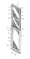
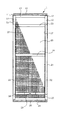
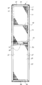
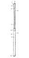
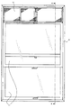
図1は、仮網戸1の伸長状態を示す斜視図である。図2は、仮網戸1の収縮状態を示す正面図である。図3は、仮網戸1の伸長状態を示す正面図である。図4は、仮網戸1の伸長状態を示す側面図である。
First, the structure of the
FIG. 1 is a perspective view showing an extended state of the
図1乃至図4に示すように、仮網戸1は、第一網戸体11及び第二網戸体21の2枚の網戸体を上下に摺動可能にそれぞれの一面を重ね合せて接続することにより構成されている。
As shown in FIGS. 1 to 4, the
第一網戸体11は、左右一対の縦枠12と上下一対の横枠(上枠13及び下枠14)とによって四辺を囲うように組まれた枠体に網部15を張設することによって構成されている。網部15は、その四辺を枠体(縦枠12、上枠13及び下枠14)に接着剤等により固定されている。本実施形態においては、仮網戸1を設置したときに外側(バルコニー側)に位置する面に網部15は取り付けられているが、これに限定されるものではない。
The first
上枠13の外側部分(上側部分)は、仮網戸1の上部端面となる部分であるが、その外側部分には、滑り止めも兼用する摩擦係数が高いゴムやクッションスポンジ等の緩衝部材16が接着剤等により上枠13の長手方向に沿って固定されている。緩衝部材16は、本実施形態のように上枠13の外側部分全面に備えることとしてもよいし、一部に備えることとしてもよい。
また、左右両方の縦枠12の外側部分には、繊維を束ねたブラシ状の摩擦軽減部材17が接着剤等により縦枠12の長手方向に沿って固定されている。摩擦軽減部材17は、本実施形態のように左右両方の縦枠12の外側部分全面に備えることとしてもよいし、一部に備えることとしてもよい。
An outer portion (upper portion) of the
A brush-like
第一網戸体11は、第二網戸体21の内側領域にて上下に摺動可能に接続されているが、第一網戸体11を摺動させやすいように、第一網戸体11の略中央部分に左右の縦枠12を連絡した状態で設置された把持部18を備えている。把持部18は、第一網戸体11を摺動させる際にハンドルの役目を果たす。なお、本実施形態では、把持部18は、人の手で握りやすいように円柱形状となっている。
また、摺動可能な第一網戸体11を任意の位置で固定するために、下枠14の略中央部分に固定ネジ19を備えている。固定ネジ19は、下枠14の内部で不図示の固定手段に螺合されており、固定ねじを締め付けると第一網戸体11が摺動不能になる構成である。
The first
Further, in order to fix the slidable first
第二網戸体21は、左右一対の縦枠22と上下一対の横枠(上枠23及び下枠24)とによって四辺を囲うように組まれた枠体に網部25を張設することによって構成されている。網部25は、その四辺を枠体(縦枠22、上枠23及び下枠24)に接着剤等により固定されている。本実施形態においては、仮網戸1を設置したときに外側(バルコニー側)に位置する面に網部25は取り付けられているが、これに限定されるものではない。また、上枠23は、第一網戸体11と干渉しない形状である。
The second
下枠24の外側部分(下側部分)は、仮網戸1の下部端面となる部分であるが、その外側部分には、滑り止めも兼用する摩擦係数が高いゴムやクッションスポンジ等の緩衝部材26が接着剤等により下枠24の長手方向に沿って固定されている。緩衝部材26は、本実施形態のように下枠24の外側部分全面に備えることとしてもよいし、一部に備えることとしてもよい。
また、左右両方の縦枠22の内側部分には、第一網戸体11の縦枠12を摺動可能に保持するための摺動溝27が、縦枠22の長手方向に沿って形成されている。
An outer portion (lower portion) of the
In addition, sliding
上記構成の第一網戸体11と第二網戸体21は、摺動可能に組み合わせて接続されているが、具体的には、第一網戸体11の縦枠12の外側部分が第二網戸体21の縦枠22の内側部分に形成された摺動溝27に対向する状態で上下に摺動可能に嵌め込まれている。
このとき、本実施形態では、第一網戸体11の縦枠12の外側部分には摺動を補助するための摩擦軽減部材17を備えているので、縦枠12と摺動溝27とが直接接触することなく、摩擦軽減部材17を介した状態となっている。そのため、第一網戸体11の摺動がスムーズになる。
なお、摩擦軽減部材17は、第一網戸体11と第二網戸体21の摺動箇所に設けてあればよいので、本実施形態のような第一網戸体11の縦枠12の外側部分ではなく、第二網戸体21の摺動溝27側に備えることとしてもよい。
Although the 1st
At this time, in this embodiment, since the outer portion of the
In addition, since the
仮網戸1の高さ寸法を調整する場合、例えば、図2に示す収縮状態から図3に示す伸長状態に変形する際には、第一網戸体11の下枠14に備えられた固定ネジ19を緩め、把持部18を持って第一網戸体11を上方に引き上げる。このとき、第一網戸体11の縦枠12は、第二網戸体21の縦枠22に形成された摺動溝27内を摺動することにより移動する。そして、任意の高さ位置まで引き上げたら、固定ネジ19を締め付けて第一網戸体11を摺動不能にして固定する。
When adjusting the height dimension of the
次に、上述した仮網戸1の使用方法、すなわち、仮網戸1を使用した建造物の修繕工事方法について説明する。本実施形態では、一例として、サッシレール4上を移動する引き違いの窓2を備えた窓額縁3に仮網戸1を設置する場合について説明する。
図5は、仮網戸1を窓2に設置した状態を示す概略図である。図6は、図5のA−A線断面図である。
Next, the usage method of the
FIG. 5 is a schematic diagram showing a state in which the
建造物の修繕工事が開始されると、まず、窓2の一部を開放して通気領域(隙間)を確保し、室内を通気可能状態とする。このとき、窓2を開ける幅は、仮網戸1の横幅と同等かやや狭い範囲とする。例えば、仮網戸1の横幅が25cmであれば、窓2を約25cmまで開けることができる。
When the repair work of the building is started, first, a part of the window 2 is opened to secure a ventilation region (gap), and the room is made to be in a state that allows ventilation. At this time, the width for opening the window 2 is set to be equal to or slightly narrower than the lateral width of the
窓2を開けて通気領域を確保した後、その通気領域を覆うように、サッシレール4上の窓2の移動領域とは重複しない位置であって、その窓2が移動するサッシレール4よりも室内側の窓額縁3に仮網戸1を設置する。
具体的には、窓2の高さ(厳密には窓額縁3の高さ)に合わせて、仮網戸1の高さ寸法を調整する。仮網戸1の高さ寸法を窓額縁3の高さに合せたら、仮網戸1の下端部分に備える緩衝部材26を下側の窓額縁3に当接させ、仮網戸1の上端部分に備える緩衝部材16を上側の窓額縁3に当接させることにより、窓額縁3に仮網戸1を固定する。このとき、仮網戸1の上下端面には緩衝部材16,26を備えているので、窓額縁3が傷付く心配もない。また、緩衝部材16,26は、摩擦係数が高く滑り止め効果も有しているので、仮網戸1を窓額縁3に安定して保持することができる。
なお、仮網戸1を設置する際には、仮網戸1の高さを窓額縁3の高さよりもやや低くして仮留めしておき、窓額縁3に嵌め込んでからさらに伸長させて高さを適合させるようにすると設置しやすい。
After the window 2 is opened and the ventilation area is secured, the position is not overlapped with the moving area of the window 2 on the sash rail 4 so as to cover the ventilation area, and the window 2 moves more than the moving sash rail 4. A
Specifically, the height dimension of the
When installing the
本実施形態では、仮網戸1は、窓2よりも室内側の窓額縁3に設置されている。このように、窓額縁3に設置した仮網戸1は、サッシレール4上の窓2の移動領域とは重複しないため、仮網戸1は一度設置したら、設置したままで窓2を完全に閉めることができ施錠することもできる。また、外(バルコニー側)に出たい場合は、仮網戸1を設置したまま、さらに窓2を開ければよい。
また、補助錠を使用すれば、通気領域を確保したまま窓2を施錠することもできる。さらに、仮網戸1の伸縮を可能とする固定ネジ19は室内側に位置するので、外部からは仮網戸1を収縮させて取外すこともできない。
In the present embodiment, the
Further, if an auxiliary lock is used, the window 2 can be locked with the ventilation region secured. Furthermore, since the fixing
このように、本実施形態では、大規模修繕工事等の建造物の修繕工事期間中、室内に備えられた窓2の一部を開放して通気領域を確保し、その通気領域に仮網戸1を簡単に設置することにより、風通しが良くなり室内を効率良く換気することができるうえ、虫や異物等の外からの侵入を好適に防止することができる。そのため、居住者は、工事期間中であっても安全で快適な生活環境を保持することができる。
As described above, in the present embodiment, during the repair work of the building such as a large-scale repair work, a part of the window 2 provided in the room is opened to secure a ventilation area, and the
<他の実施形態>
次に、本発明の変形例である他の実施形態について図7及び図8を参照して説明する。
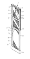
図7は、他の実施形態に係る仮網戸1の斜視図である。図8は、他の実施形態に係る仮網戸1の要部を示す部分断面図であり、(a)はケーシング31内のスプリング32が伸長した状態を示し、(b)はスプリング32が収縮した状態を示すものである。
<Other embodiments>
Next, another embodiment which is a modification of the present invention will be described with reference to FIGS.
FIG. 7 is a perspective view of a
他の実施形態における仮網戸1は、図7及び図8に示すように、付勢手段であるスプリング32を内部に備えたケーシング31が、第二網戸体21に取付けられていることに特徴を有する。
具体的には、ケーシング31は、第二網戸体21の縦枠22の一部と下枠24とをケーシング31の内側領域にて上下に摺動可能な状態で嵌め込むことにより、第二網戸体21と接続されている。このとき、下枠24の外側部分(下側部分)は、ケーシング31内のスプリング32と接しており、そのスプリング32により、第二網戸体21全体が上方向へ付勢されている。
As shown in FIGS. 7 and 8, the
Specifically, the
この他の実施形態における仮網戸1を窓額縁3に設置する場合、仮網戸1の下端面(第二網戸体21に取り付けられたケーシング31の下端面)を下側の窓額縁3に当接させ、さらに仮網戸1を下方向に押さえつけることにより、図8(b)に示すようにスプリング32を収縮させる。そして、スプリング32を収縮させた状態で、仮網戸1の上端面(緩衝部材16)を上側の窓額縁3に嵌め込み当接させる。仮網戸1の上端面が上側の窓額縁3に当接すると、スプリング32の付勢力により仮網戸1は窓額縁3にしっかりと適合する。
このように、付勢手段であるスプリング32を備えた他の実施形態の仮網戸1であれば、仮網戸1の設置がさらに容易になると共に、設置した仮網戸1を安定して保持することができる。
When installing the
Thus, if it is the
また、他の実施形態における仮網戸1は、図7に示すように、不図示の窓額縁3等に備えた突起部等に引っ掛けて吊るための落下防止手段であるワイヤー33を第一網戸体11の上枠13に備えたことに特徴を有する。
ワイヤー33は、伸縮自在の紐から成り、その一端には第一網戸体11の上枠13に形成された孔に連結されたフックが備え付けられており、他端である自由端側には円環部分を有している。仮網戸1を窓額縁3に設置したとき、ワイヤー33の円環部分を窓額縁3等の突起部等に引っ掛けて固定することにより、設置した仮網戸1をさらに安定して保持することができ、揺れや振動等でも仮網戸1が外れ難くなる。
In addition, as shown in FIG. 7, the
The
上記の実施形態では、主として本発明の建造物の修繕工事方法及びその建造物の修繕工事の際に使用する仮網戸について説明した。
ただし、上記の実施形態は、本発明の理解を容易にするための一例に過ぎず、本発明を限定するものではない。本発明は、その趣旨を逸脱することなく、変更、改良され得ると共に、本発明にはその等価物が含まれることは勿論である。
In the above embodiment, the building repair method of the present invention and the temporary screen used for the repair of the building have been described.
However, said embodiment is only an example for making an understanding of this invention easy, and does not limit this invention. The present invention can be changed and improved without departing from the gist thereof, and the present invention includes the equivalents thereof.
1 仮網戸
2 窓
3 窓額縁
4 サッシレール
11 第一網戸体
12 縦枠
13 上枠
14 下枠
15 網部
16 緩衝部材
17 摩擦軽減部材
18 把持部
19 固定ネジ
21 第二網戸体
22 縦枠
23 上枠
24 下枠
25 網部
26 緩衝部材
27 摺動溝
31 ケーシング
32 スプリング
33 ワイヤー
DESCRIPTION OF
Claims (8)
前記建造物の室内に備えられた窓の一部を開放して前記室内を通気可能状態とし、
前記窓を開放した部分の前記窓よりも室内側に仮網戸を設置して通気領域を前記仮網戸で覆うことを特徴とする建造物の修繕工事方法。 In the method of repairing buildings,
Opening a part of the window provided in the room of the building and allowing the room to ventilate,
A method for repairing a building, wherein a temporary screen door is installed on the indoor side of the window where the window is opened and the ventilation area is covered with the temporary screen door.
前記室内の窓額縁に前記仮網戸の上部及び下部を当接させて固定することを特徴とする請求項1に記載の建造物の修繕工事方法。 The temporary screen is a structure that can be expanded and contracted vertically,
The method for repairing a building according to claim 1, wherein the upper and lower parts of the temporary screen door are brought into contact with and fixed to the window frame in the room.
左右一対の縦枠と上下一対の横枠とからなる枠体に網を張設して成る第一網戸体と、
前記第一網戸体を上下に摺動可能に保持するものであって、左右一対の縦枠と上下一対の横枠とからなる枠体に網を張設して成る第二網戸体と、
を備えたことを特徴とする仮網戸。 A temporary screen door that is installed on the indoor side of the window of a part of the window provided in the room of the building, the opening of the window,
A first screen door body formed by stretching a net on a frame body composed of a pair of left and right vertical frames and a pair of upper and lower horizontal frames;
The first screen door body is slidably held up and down, and a second screen door body formed by stretching a net on a frame body composed of a pair of left and right vertical frames and a pair of upper and lower horizontal frames,
Temporary screen door characterized by comprising.
前記第一網戸体の前記縦枠の外側を前記摺動溝に対向するように摺動可能に組み合わせたことを特徴とする請求項3に記載の仮網戸。 A sliding groove is provided inside the vertical frame of the second screen door body,
The temporary screen door according to claim 3, wherein the first screen door body is slidably combined so that the outside of the vertical frame faces the sliding groove.
The temporary screen door according to any one of claims 3 to 7, wherein the first screen door body or the second screen door body is provided with a fall prevention means.
Priority Applications (1)
| Application Number | Priority Date | Filing Date | Title |
|---|---|---|---|
| JP2016092768A JP2017201092A (en) | 2016-05-02 | 2016-05-02 | Repair method of building structure and temporary window screen |
Applications Claiming Priority (1)
| Application Number | Priority Date | Filing Date | Title |
|---|---|---|---|
| JP2016092768A JP2017201092A (en) | 2016-05-02 | 2016-05-02 | Repair method of building structure and temporary window screen |
Publications (1)
| Publication Number | Publication Date |
|---|---|
| JP2017201092A true JP2017201092A (en) | 2017-11-09 |
Family
ID=60264647
Family Applications (1)
| Application Number | Title | Priority Date | Filing Date |
|---|---|---|---|
| JP2016092768A Pending JP2017201092A (en) | 2016-05-02 | 2016-05-02 | Repair method of building structure and temporary window screen |
Country Status (1)
| Country | Link |
|---|---|
| JP (1) | JP2017201092A (en) |
Citations (5)
| Publication number | Priority date | Publication date | Assignee | Title |
|---|---|---|---|---|
| JPS54147041U (en) * | 1978-04-04 | 1979-10-12 | ||
| JPS5693493U (en) * | 1979-12-20 | 1981-07-24 | ||
| JPS57172898U (en) * | 1981-04-24 | 1982-10-30 | ||
| JP2001115760A (en) * | 1999-10-21 | 2001-04-24 | Fujiyama Kensetsu:Kk | Window screen device |
| JP2005350932A (en) * | 2004-06-09 | 2005-12-22 | Kawaguchi Giken Inc | Wire screen device |
-
2016
- 2016-05-02 JP JP2016092768A patent/JP2017201092A/en active Pending
Patent Citations (5)
| Publication number | Priority date | Publication date | Assignee | Title |
|---|---|---|---|---|
| JPS54147041U (en) * | 1978-04-04 | 1979-10-12 | ||
| JPS5693493U (en) * | 1979-12-20 | 1981-07-24 | ||
| JPS57172898U (en) * | 1981-04-24 | 1982-10-30 | ||
| JP2001115760A (en) * | 1999-10-21 | 2001-04-24 | Fujiyama Kensetsu:Kk | Window screen device |
| JP2005350932A (en) * | 2004-06-09 | 2005-12-22 | Kawaguchi Giken Inc | Wire screen device |
Similar Documents
| Publication | Publication Date | Title |
|---|---|---|
| US20130000082A1 (en) | Safety retainer for curtain cord | |
| KR101219091B1 (en) | Functional green windows | |
| KR100580187B1 (en) | Rainwater blinder of veranda | |
| KR200490118Y1 (en) | protection against wind and soundproof system for windows door | |
| KR101925873B1 (en) | Remodeling window unit | |
| KR101643646B1 (en) | Window for crime prevention insect window | |
| KR20130059586A (en) | Vermin preventing window stopper and sliding window having the same | |
| KR20130005332A (en) | Windows structure for repairing and method by using that | |
| KR101044837B1 (en) | Mothproof apparatus linked with a chassis | |
| JP2017201092A (en) | Repair method of building structure and temporary window screen | |
| KR101694244B1 (en) | Screens for Railing | |
| JP7028470B2 (en) | Sliding fittings | |
| KR200466679Y1 (en) | Roll mosquito net | |
| KR101930728B1 (en) | One Body Type Mosquito Net Window | |
| KR200442991Y1 (en) | High-rise casement doors | |
| KR101102951B1 (en) | Door frame for cleanroom | |
| KR200456513Y1 (en) | Safety guardrail for window | |
| KR101160945B1 (en) | Use the korea paper and lumber window stomrm window system and the construction method | |
| JP4755664B2 (en) | Finishing wood for foundation finishing and finishing method of foundation | |
| KR101449709B1 (en) | Shading apparatus for bunk beds | |
| KR20070000596U (en) | Emergency escape device for apartment balcony | |
| KR20190115825A (en) | A protection against wind using door an insert net door | |
| KR20110117827A (en) | Water preventing apparatus for windows and doors | |
| KR101242318B1 (en) | the roll screen system for a wind resistance | |
| KR20120004020U (en) | Blind that do so that both sides washing of glass window may be available |
Legal Events
| Date | Code | Title | Description |
|---|---|---|---|
| A621 | Written request for application examination |
Free format text: JAPANESE INTERMEDIATE CODE: A621 Effective date: 20180329 |
|
| A977 | Report on retrieval |
Free format text: JAPANESE INTERMEDIATE CODE: A971007 Effective date: 20190129 |
|
| A131 | Notification of reasons for refusal |
Free format text: JAPANESE INTERMEDIATE CODE: A131 Effective date: 20190219 |
|
| A02 | Decision of refusal |
Free format text: JAPANESE INTERMEDIATE CODE: A02 Effective date: 20190827 |