JP2017197277A - Container with measurement device - Google Patents
Container with measurement device Download PDFInfo
- Publication number
- JP2017197277A JP2017197277A JP2016092018A JP2016092018A JP2017197277A JP 2017197277 A JP2017197277 A JP 2017197277A JP 2016092018 A JP2016092018 A JP 2016092018A JP 2016092018 A JP2016092018 A JP 2016092018A JP 2017197277 A JP2017197277 A JP 2017197277A
- Authority
- JP
- Japan
- Prior art keywords
- cap
- measuring
- container
- chamber
- content liquid
- Prior art date
- Legal status (The legal status is an assumption and is not a legal conclusion. Google has not performed a legal analysis and makes no representation as to the accuracy of the status listed.)
- Granted
Links
Images


Abstract
Description
本発明は計量装置付容器に関する。 The present invention relates to a container with a weighing device.
容器本体の内容液を例えば1日の使用分量だけ計量して吐出できるようにした計量装置付容器として、特許文献1に記載のものがある。 There exists a thing of patent document 1 as a container with a measuring device which enabled it to measure and discharge the content liquid of a container main body only for the usage-amount of a day, for example.
この計量装置付容器は、プラスチックボトル等の可撓性物質により形成された容器本体と、容器本体に取付けられ、容器本体の内容液が該容器本体のスクイズ変形によって加圧されて注出される注出口を備えた注出キャップと、注出キャップに設けられ、注出キャップの注出口から注出された内容液が貯留される計量室を備えた計量キャップとを有して構成される。計量キャップの計量室に貯留された所定量の内容液は、容器を傾けることによって、計量室の上部に設けられている開口部から注出される。 This container with a weighing device is attached to a container body formed of a flexible material such as a plastic bottle, and the container body, and the liquid in the container body is pressurized and poured out by squeeze deformation of the container body. A pouring cap provided with an outlet and a measuring cap provided in the pouring cap and provided with a measuring chamber in which the content liquid poured out from the pouring outlet of the pouring cap is stored. A predetermined amount of content liquid stored in the measuring chamber of the measuring cap is poured out from an opening provided in the upper portion of the measuring chamber by tilting the container.
ここで、計量キャップに設けられる計量室の上部に設けられている開口部は、計量室に貯留した内容液を外部へ吐出可能にする吐出口として機能するだけでなく、計量室の上部空間を外部に連通する空気置換口としても機能する。即ち、計量時には、容器本体のスクイズ変形によって加圧されて注出キャップの注出口から計量キャップの計量室に注出された容器本体の内容液が、計量室の内部の空気を空気置換口としての上記開口部から外部に押出す。また、計量後に容器本体のスクイズ変形を復元するときには、外部の空気を空気置換口としての上記開口部から計量キャップの計量室、及び注出キャップの注出口経由で容器本体の内部に吸込む。 Here, the opening provided in the upper portion of the measuring chamber provided in the measuring cap not only functions as a discharge port that allows the content liquid stored in the measuring chamber to be discharged to the outside, but also opens the upper space of the measuring chamber. It also functions as an air replacement port communicating with the outside. That is, at the time of measurement, the content liquid in the container body pressurized by the squeeze deformation of the container body and poured out from the spout of the dispensing cap into the measuring chamber of the measuring cap uses the air inside the measuring chamber as the air replacement port. It extrudes from the said opening part of the outside. When restoring the squeeze deformation of the container body after weighing, external air is sucked into the container body from the opening serving as an air replacement port via the weighing chamber of the measuring cap and the spout of the dispensing cap.
従来の計量装置付容器には以下の問題点がある。
(1)計量キャップにおける計量室の上部に設けられている開口部が吐出口と空気置換口を兼用している。従って、内容液の前回吐出時に吐出口としての上記開口部に付着していた残液が、容器本体をスクイズ変形して行なう次回計量時に計量室の内部から空気置換口としての上記開口部を経て外部に押出される空気の流れによって外部に吹き出され、該開口部からしずくになって垂れ落ちるおそれがある。
A conventional container with a weighing device has the following problems.
(1) The opening provided in the upper part of the measuring chamber in the measuring cap serves as both the discharge port and the air replacement port. Therefore, the residual liquid adhering to the opening as the discharge port at the time of the previous discharge of the content liquid passes through the opening as the air replacement port from the inside of the measuring chamber at the next measurement performed by squeezing the container body. There is a possibility that the air will be blown out by the flow of air pushed out and fall down from the opening.
(2)計量キャップにおける計量室の上部に開口部が設けられているため、内容液の計量時に急速にスクイズ変形された容器本体の注出口から勢い良く注出される内容液が、稀に上記開口部から外部に飛散するおそれがある。 (2) Since the opening is provided in the upper part of the measuring chamber in the measuring cap, the content liquid that is rapidly poured out from the spout of the container body that is rapidly squeezed when measuring the content liquid is rarely the above opening. There is a risk of splashing outside from the section.
(3)容器を傾けることによって、計量キャップの計量室に貯留した内容液を、該計量室の上部に設けた開口部から外部へ吐出させるものであるため、吐出時に容器本体を把持した手首の傾け角度が大きくなって吐出操作性が悪い。 (3) By tilting the container, the content liquid stored in the measuring chamber of the measuring cap is discharged to the outside from the opening provided in the upper part of the measuring chamber. The tilt angle becomes large and the discharge operability is poor.
本発明の課題は、計量キャップの吐出口に付着していた前回吐出時の残液が、容器本体をスクイズ変形して行なう次回計量時に該吐出口からしずくになって垂れ落ちるのを防止することにある。 It is an object of the present invention to prevent the remaining liquid that has adhered to the discharge port of the measurement cap from dripping from the discharge port during the next measurement performed by squeezing the container body the next time. It is in.
本発明の他の課題は、容器本体のスクイズ変形によって加圧されて注出キャップの注出口から注出される内容液の外部への飛散を確実に防止することにある。 Another object of the present invention is to reliably prevent the content liquid, which is pressurized by the squeeze deformation of the container body and poured out from the spout of the pouring cap, from being scattered to the outside.
本発明の他の課題は、容器を大きく傾けることなく、計量キャップの計量室に貯留した内容液を吐出可能にすることにある。 Another object of the present invention is to enable discharge of the liquid stored in the measuring chamber of the measuring cap without greatly tilting the container.
請求項1に係る発明は、可撓性物質により形成された容器本体と、容器本体に取付けられ、容器本体の内容液が該容器本体のスクイズ変形によって加圧されて注出される注出口を備えた注出キャップと、注出キャップに接続され、注出キャップの注出口から注出された内容液が貯留される計量室を備えた計量キャップとを有してなる計量装置付容器であって、計量キャップが、計量室に貯留した内容液を外部へ吐出可能にする吐出口と、計量室の上部空間を外部に連通可能にする空気置換口とを互いに別個に設けてなるようにしたものである。 The invention according to claim 1 includes a container main body formed of a flexible substance, and a spout attached to the container main body, the content liquid of the container main body being pressurized and poured out by squeeze deformation of the container main body. A container with a weighing device comprising a dispensing cap and a weighing cap connected to the dispensing cap and provided with a weighing chamber for storing the content liquid dispensed from the dispensing outlet of the dispensing cap. The metering cap has a discharge port that allows the content liquid stored in the measurement chamber to be discharged to the outside, and an air replacement port that allows the upper space of the measurement chamber to communicate with the outside. It is.
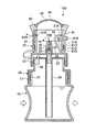
図1乃至図4に示した計量装置付容器100は、容器本体10と注出キャップ20と計量キャップ30とを有して構成される。計量装置付容器100にあっては、容器本体10がテーブル等の上に載置された正立状態(図1)で、容器本体10の側を下方、計量キャップ30の側を上方と称するものとする。
The
容器本体10は、プラスチック等の可撓性物質により形成され、下端閉塞、上端開口状の筒状体からなり、調味料、育毛剤、薬剤等の内容液が収容される。容器本体10の上端側外周部には注出キャップ20が螺着される外周ねじ11が形成される。
The
注出キャップ20は、プラスチック等により形成され、下端開口、上端閉塞状の筒状体からなる。注出キャップ20は、容器本体10の外周ねじ11に螺着される内周ねじ21を下端側内周部に備え、容器本体10に取付けられる。注出キャップ20は、計量キャップ30が螺着される外周ねじを上端側外周部に備える。
The dispensing
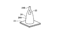
注出キャップ20は、筒状体の上端に天面部23を設け、この天面部23を上下に貫通するように設けた注出管部24を該天面部23の中央部に備える。天面部23の上面から上方に突出する注出管部24の上端部は、図5乃至図7に示す如く、有頂尖り状をなすものとされている。この尖り状部24Aは、頂部24Bを閉塞され、頂部24B近傍の周方向複数位置に注出口25を開口している。天面部23の下面から下方に突出する注出管部24の下端部には、容器本体10の底部まで届くディップチューブ26が嵌着されている。容器本体10のスクイズ変形によって加圧される容器本体10の内容液が、ディックチューブ26を経て注出管部24の注出口25から注出されるようになっている。注出口25から注出された内容液は計量キャップ30の計量室32に供給されて貯留される。
The
計量キャップ30は、貯留室32を形成する計量本体部31を備えるとともに、計量本体部31に取付けられて計量室32の上部空間を被覆し、外部に対して封止する被覆部40を備える。
The
計量本体部31は、プラスチック等により形成され、上下両側開口状の筒状体からなる。計量本体部31は、筒状体における上下方向の中間部に底面部33を設け、この筒状体における底面部33の上部に計量室32を形成するとともに、この筒状体における底面部33の下部に位置する下端側内周部に内周ねじ34を備える。計量本体部31は内周ねじ34を注出キャップ20の外周ねじ22に螺着して該注出キャップ20に接続される。
The measurement
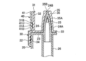
計量本体部31は、図5、図6、図8に示す如く、底面部33の中央部に筒状の注出口開閉部35を備える。注出口開閉部35は、注出制御手段36を構成するものであり、底面部33の上面から上方に突出する下端開口の筒状体35Aからなるとともに、筒状体35Aの上端に通液口35Bを設けている。即ち、計量本体部31が注出キャップ20に設けられたとき、注出口開閉部35の筒状部35Aが、注出キャップ20の天面部23から突出している注出管部24の尖り状部24Aに被着される。注出口開閉部35は、筒状部35Aの通液口35Bが注出管部24における尖り状部24Aの頂部24Bに対して液密に嵌合する位置と、離隔する位置とに切換設定される。これにより、注出口開閉部35は注出管部24の注出口25から計量室32への内容液の注出経路を開閉し、注出キャップ20の注出口25から計量キャップ30の計量室32への内容液の注出を停止できる注出制御手段36を構成する。
As shown in FIGS. 5, 6, and 8, the measurement
即ち、計量本体部31の内周ねじ34が注出キャップ20の外周ねじ22に螺動され、計量キャップ30が注出キャップ20に対して上下移動可能にされるとき、計量キャップ30が下降端に到達して注出口開閉部35の通液口35Bが注出管部24における尖り状部24Aの頂部24Bに液密に嵌合するに至ると、通液口35Bが閉塞されて注出口25から計量室32への注出経路が閉じる。即ち、計量キャップ30は注出口25から計量室32への内容液の注出を停止する注出停止位置(図1、図3、図4、図5)に切換設定されたものになる。
That is, when the inner
他方、計量キャップ30が上述の下降端から上昇し、注出口開閉部35の通液口35Bが尖り状部24Aの頂部24Bから離れると、通液口35Bが開かれて注出口25から計量室32への注出経路を開く。即ち、計量キャップ30は注出口25から計量室32へ内容液を注出する注出位置(図2、図6)に切換設定されたものになる。
On the other hand, when the measuring
尚、図6では、計量キャップ30の注出口開閉部35における筒状部35Aの下端側内周面と、注出キャップ20の注出管部24における尖り状部24Aの下端側外周面との間に隙間があるように図示されているが、この隙間は実際にはない。即ち、計量キャップ30が図6に示す如くの注出位置に設定されるとき、計量キャップ30の注出口開閉部35における筒状部35Aの下端側内周面は、注出キャップ20の注出管部24における尖り状部24Aの下端側外周面と液密に摺接し、注出口25から計量室30へ注出される液が筒状部35Aの下端側内周面と尖り状部24Aの下端側外周面の間から計量室32の底面部33と注出キャップ20の天面部23との間のスペース(図2、図6)に漏れ出るおそれがない。
In FIG. 6, the lower end side inner peripheral surface of the
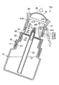
被覆部40は、プラスチック等にて構成される有天筒状体からなり、筒部41と天面部42とを備え、計量キャップ30を構成する計量本体部31の上端側外周部に嵌着され、計量室32の上部空間を被覆する。
The covering
被覆部40は、筒部41が計量本体部31の上端側外周部に回り止めされた状態で上下移動可能に、かつ隙間なく嵌着され、下降側位置では、筒部41の下端面を計量本体部31の中間外周部に設けた肩部31Sに衝合し、かつ筒部41の下端側内周部に設けた上下一対の環状ストッパ41U、41Dを計量本体部31の上端側外周部に設けた下側環状係合部31Aの上縁部と下縁部に係合して停留される。また、被覆部40の筒部41は、計量本体部31の筒状体に対して下降側位置から引き上げられた上昇側位置で、筒部41の上下一対の環状ストッパ41U、41Dを計量本体部31の上端側外周部における上記下側環状係合部31Aの上部に設けた上側環状係合部31Bの上縁部と下縁部に係合して停留される。
The covering
計量キャップ30は、被覆部40における筒部41の計量本体部31に対する前述の回り止め嵌着状態で、計量本体部31の筒状体の上部と筒部41の上部における周方向同一位置のそれぞれに吐出口31Kと吐出口41Kを設けている。計量本体部31に設けた吐出口31Kにはディップチューブ43の一端が接続され、ディップチューブ43の他端は計量室32の底部まで延在されている。また、計量キャップ30は、被覆部40における筒部41の計量本体部31に対する前述の回り止め嵌合状態で、計量本体部31の筒状体の上部と筒部41の上部における周方向同一位置のそれぞれに空気置換口31Rと空気置換口41Rを設けている。吐出口31K及び41Kと空気置換口31R及び41Rとは、計量本体部31及び筒部41の周方向で互いに異なる位置に設けられる。吐出口31K、空気置換口31Rは計量室32に常時臨み、吐出口41K、空気置換口41Rは外部空間に常時臨むものとされている。
The measuring
尚、計量キャップ30において、注出キャップ20の注出口25から計量室32に供給され、貯留される内容液が空気置換口31R、41Rに付着する機会が可及的に発生しないように、計量本体部31、筒部41に設けられる空気置換口31R、41Rの位置は、計量室32に供給される内容液の液面レベルより十分に高位置に設定される。また、計量キャップ30の吐出口31K、41Kからの内容液の吐出時には、容器100の姿勢が吐出口41Kの液吐出方向を少し斜め下向きにするように設定されがちになり、計量室32内の液面が吐出口31K、41K寄りで高くなることから、空気置換口31R、41Rは容器10の中心軸を挟んで吐出口31K、41Kの反対側となる位置に設定されることが好ましい。
It should be noted that the
そして、被覆部40の筒部41が計量本体部31に対して上下移動され、筒部41が前述の下降側位置に設定されたとき、被覆部40は、吐出口41Kが吐出口31Kと非連通とされてそれらの吐出口41K、31Kをそれらの吐出口41K、31Kの計量室32から外部空間への導通を閉じ状態にし、かつ空気置換口41Rが空気置換口31Rと連通されてそれらの空気置換口41R、31Rの計量室32から外部空間に対する導通を開き状態とする計量位置(図2)に設定されるものになる。また、被覆部40の筒部41が前述の上昇側位置に設定されたとき、被覆部40は、吐出口41Kが吐出口31Kと連通されてそれらの吐出口41K、31Kの計量室32から外部空間に対する導通を開き状態にし、かつ空気置換口41Rが空気置換口31Rと非連通とされてそれらの空気置換口41R、31Rの計量室32から外部空間に対する導通を閉じ状態とする吐出位置(図3、図4)に設定されるものになる。
And when the
即ち、計量装置付容器100にあっては、計量キャップ30が、計量室32に貯留した内容液を外部へ吐出可能にする吐出口31K及び41Kと、計量室32の上部空間を外部に連通可能にする空気置換口31R及び41Rとを互いに別個に設けている。そして、内容液が注出キャップ20の注出口25から前述の如くに注出されて計量キャップ30の計量室32に貯留されるときには、被覆部40が前述の計量位置に設定されて吐出口31K、41Kが閉じられ、空気置換口31R、41Rが開かれる。他方、計量キャップ30の計量室32に貯留した内容液が吐出されるときには、被覆部40が前述の吐出位置に設定されて吐出口31K、41Kが開かれ、空気置換口31R、41Rが閉じられるものになる。
That is, in the
更に、計量装置付容器100にあっては、計量キャップ30の計量室32を加圧できる加圧操作部44を有する。本実施例では、計量キャップ30における計量室32の上部空間を被覆している被覆部40の天面部42をエラストマー等の弾性変形できる材質からなるものにし、この弾性変形できる天面部42により加圧操作部44を構成するものにした。加圧操作部44としての天面部42を押圧変形することによって計量室32の容積を減縮し、該計量室32の内圧を高圧化させるものである。
Furthermore, the
即ち、前述の注出制御手段36(注出口開閉部35)により注出キャップ20の注出口25から計量キャップ30の計量室32への内容液の注出が停止され、かつ被覆部40が前述の吐出位置に設定されて吐出口31K、41Kが開かれ、空気置換口31R、41Rが閉じられた状態下で、加圧操作部44により計量室32が加圧されることで、計量室32に貯留されていた内容液がディップチューブ43経由で注出口31K、41Kから外部へと吐出される。
That is, the dispensing control means 36 (the dispensing opening / closing portion 35) stops the dispensing of the content liquid from the dispensing
尚、計量装置付容器100は、計量キャップ30の計量室32が見え易いように、計量本体部31及び被覆部40(筒部41、天面部42)を透明又は半透明の材料で形成することが好ましい。
In the
従って、計量装置付容器100は以下の如くに使用される。
(1)使用前状態(図1)
容器本体10に内容液が収容された状態で、計量キャップ30の計量本体部31が注出キャップ20に対する下降端に設定され、計量キャップ30の注出口開閉部35(注出制御手段36)が注出キャップ20の注出口25から計量室32への内容液の注出経路を閉じる。これにより、店頭陳列時を含む使用前段階で、容器本体10の内容液の不測の漏れが防止される。
Therefore, the
(1) State before use (Fig. 1)
In a state where the content liquid is stored in the container
(2)計量状態(図2)
被覆部40の筒部41が計量キャップ30の計量本体部31に対する下降側位置に設定され、被覆部40が吐出口41K、31Kを閉じ、かつ空気置換口41R、31Rを開く計量位置に設定される。
(2) Weighing state (Fig. 2)
The
また、使用者が計量キャップ30を注出キャップ20に対して回転操作することにより、計量キャップ30の計量本体部31が注出キャップ20に対する下降端から上方に螺動され、計量キャップ30の注出口開閉部35(注出制御手段36)が注出キャップ20の注出口25から計量室32への内容液の注出経路を開く。
Further, when the user rotates the measuring
使用者が容器本体10をスクイズ変形することにより、容器本体10の内容液がディップチューブ26を通り、注出キャップ20の注出口25から計量室32に供給される。計量室32の液が注出管部24における注出口25の上端レベルの高さに達すると、それを越える分の液は容器本体10が復元するときに容器本体10に戻り、計量室32内には注出口25の上端レベルまでの容積分の液(1日分等の定量の液)が貯留される。尚、計量キャップ30(計量本体部31及び被覆部40の筒部41)の周壁に設けた目盛りを見ながら容器本体10をスクイズ変形することにより、上記定量よりも少ない適量を計量して貯留することもできる。
When the user squeezes and deforms the
容器本体10のスクイズ変形によって計量キャップ30の計量室32に注出された液は、計量室32の上部空間の空気を空気置換口31R、41Rから外部に押出す。また、計量後に容器本体10のスクイズ変形を復元するときには、外部の空気が空気置換口31R、41Rから計量室32、注出口25経由で容器本体10の内部に吸込まれる。
The liquid poured into the measuring
(3)吐出準備状態(図3)
被覆部40の筒部41が計量本体部31に対する上昇側位置に引き上げられ、被覆部40が吐出口41K、31Kを開き、空気置換口41R、31Rを閉じる注出位置に設定される。
(3) Discharge preparation state (Fig. 3)
The
また、計量キャップ30の計量本体部31が注出キャップ20に対する下降端まで螺動され、計量キャップ30の注出口開閉部35(注出制御手段36)が注出キャップ20の注出口25から計量室32への内容液の注出経路を閉じる。
Further, the measuring
(4)吐出状態(図4)
上述(3)の吐出準備がなされた状態で、被覆部40の天面部42からなる加圧操作部44を押圧変形し、計量室32を加圧する。これにより、計量室32に貯留されていた内容液が、ディップチューブ43経由で吐出口31K、41Kから外部へと吐出される。一度の加圧操作で計量室32内に貯留した定量の液の全量を吐出できなければ、加圧操作を必要回数繰り返して全量吐出する。
(4) Discharge state (Fig. 4)
In the state where the preparation for discharge described in (3) is made, the pressurizing
本実施例によれば、以下の作用効果を奏する。
(a)計量キャップ30が、計量室32に貯留した内容液を外部へ吐出可能にする吐出口31K、41Kと、計量室32の上部空間を外部に連通可能にする空気置換口31R、41Rとを互いに別個に設けるとともに、前回吐出操作に続いて行なう次回計量時に、容器本体10のスクイズ変形によって加圧されて注出キャップ20の注出口25から計量キャップ30の計量室32に注出された内容液が、計量室32の内部の空気を押出すに際し、吐出口31K、41Kが閉じられ、空気置換口31R、41Rが開かれるものにした。従って、この次回計量時に、計量室32に注出された内容液によって上述の如くに押出される空気の全てが吐出口31K、41Kを通ることなく、空気置換口31R、41Rを通って外部に吐出されるものになる。これにより、前回吐出時に吐出口31K、41Kに付着した残液は、上述の外部に押出される空気の流れによって外部に吹き出される如くがなく、吐出口31K、41Kからしずくになって垂れ落ちるのを確実に抑制できる。
According to the present embodiment, the following operational effects can be obtained.
(a)
(b)計量キャップ30が、計量本体部31によって形成される計量室32の上部空間を被覆する被覆部40を備える。従って、内容液の計量時に急速にスクイズ変形された容器本体10の注出口25から勢い良く内容液が注出されても、この内容液は被覆部40の存在によって外部への飛散を確実に防止される。
(b) The measuring
(c)計量キャップ30の上述(b)の被覆部40が、計量本体部31に対して移動可能にされ、吐出口31K、41Kを閉じ、かつ空気置換口31R、41Rを開く計量位置と、吐出口31K、41Kを開き、かつ空気置換口31R、41Rを閉じる吐出位置とに切換設定される。従って、前述(a)による次回計量時における吐出口31K、41Kからのしずくの垂れ落ちの防止を、簡易な構成により達成できる。
(c) a measuring position in which the covering
(d)注出制御手段36により注出キャップ20の注出口25から計量キャップ30の計量室32への内容液の注出が停止され、かつ吐出口31K、41Kが開かれ、空気置換口31R、41Rが閉じられた状態下で、加圧操作部44により計量キャップ30の計量室32を加圧することにより、計量室32の内圧を逃がすことなく高圧化できる。そして、このようにして生成された高圧により、計量室32に貯留されていた内容液を加圧して吐出口31K、41Kから外部へとスムースに吐出でき、内容液の吐出にあたって容器を大きく傾ける必要がない。
(d) The dispensing control means 36 stops the dispensing of the content liquid from the dispensing
(e)計量キャップ30の上部空間を被覆して弾性変形できる被覆部40が加圧操作部44とされる。従って、簡易な構成により、上述(d)の加圧操作部44を設けることができる。
(e) The covering
(f)計量キャップ30が、注出キャップ20の注出口25から計量キャップ30の計量室32への内容液の注出経路を開閉する注出口開閉部35を備える。そして、計量キャップ30が、注出キャップ20に対して移動可能にされ、注出口開閉部35によって上記注出経路を開く注出位置と、該注出経路を閉じる注出停止位置とに切換設定される。従って、簡易な構成により、上述(d)の注出制御手段36を設けることができる。
(f) The measuring
尚、本発明は、計量キャップが、計量室に貯留した内容液を外部へ吐出可能にする吐出口と、計量室の上部空間を外部に連通可能にする空気置換口とを互いに別個に設けるものであれば良く、注出キャップの注出口から注出される内容液を計量キャップの計量室に貯留する計量時に、前述(a)の如くに吐出口を必ずしも閉じることなく、吐出抵抗の大きな吐出口を備えるものとしても良い。即ち、前回吐出操作に続いて行なう次回計量時に、容器本体のスクイズ変形によって加圧されて注出キャップの注出口から計量キャップの計量室に注出される内容液が、計量室の内部の空気を空気置換口から押出すに際し、吐出口の通路抵抗を大きく設定することもできる。これによれば、計量室に注出された内容液によって上述の如くに押出される空気の多くが吐出口を通ることなく、空気置換口を通って外部に吐出されるものになる。従って、前回吐出時に吐出口に付着した残液がこの吐出口を通って外部に押出される空気の流れにより外部に吹出され、吐出口からしずくになって垂れ落ちるのを抑制できる。 In the present invention, the measuring cap is provided with a discharge port that allows the content liquid stored in the measurement chamber to be discharged to the outside and an air replacement port that allows the upper space of the measurement chamber to communicate with the outside. The discharge port with a large discharge resistance is not necessarily closed as described above (a) during the measurement in which the content liquid discharged from the discharge port of the discharge cap is stored in the measurement chamber of the measurement cap. It is good also as a thing provided. That is, at the next measurement performed following the previous discharge operation, the content liquid pressurized by the squeeze deformation of the container body and poured out from the spout of the discharge cap into the measurement chamber of the measurement cap causes the air inside the measurement chamber to When extruding from the air replacement port, the passage resistance of the discharge port can be set large. According to this, much of the air extruded as described above by the content liquid poured into the measuring chamber is discharged outside through the air replacement port without passing through the discharge port. Accordingly, it is possible to suppress the residual liquid adhering to the discharge port during the previous discharge from being blown out by the flow of air pushed out through the discharge port and dropping from the discharge port.
本発明によれば、計量キャップの吐出口に付着していた前回吐出時の残液が、容器本体をスクイズ変形して行なう次回計量時に該吐出口からしずくになって垂れ落ちるのを防止することができる。 According to the present invention, it is possible to prevent the residual liquid that has adhered to the discharge port of the measurement cap from dripping from the discharge port during the next measurement performed by squeezing the container body. Can do.
また、本発明によれば、容器本体のスクイズ変形によって加圧されて注出キャップの注出口から注出される内容液の外部への飛散を確実に防止することができる。 In addition, according to the present invention, it is possible to reliably prevent the content liquid that is pressurized by the squeeze deformation of the container body and is poured out from the spout of the pouring cap to the outside.
また、本発明によれば、容器を大きく傾けることなく、計量キャップの計量室に貯留した内容液を吐出可能にすることができる。 Further, according to the present invention, it is possible to discharge the content liquid stored in the measuring chamber of the measuring cap without greatly tilting the container.
10 容器本体
20 注出キャップ
25 注出口
30 計量キャップ
31 計量本体部
32 計量室
35 注出口開閉部
36 注出制御手段
40 被覆部
44 加圧操作部
100 計量装置付容器
DESCRIPTION OF
Claims (7)
容器本体に取付けられ、容器本体の内容液が該容器本体のスクイズ変形によって加圧されて注出される注出口を備えた注出キャップと、
注出キャップに接続され、注出キャップの注出口から注出された内容液が貯留される計量室を備えた計量キャップとを有してなる計量装置付容器であって、
計量キャップが、計量室に貯留した内容液を外部へ吐出可能にする吐出口と、計量室の上部空間を外部に連通可能にする空気置換口とを互いに別個に設けてなる計量装置付容器。 A container body formed of a flexible material;
A pouring cap having a spout attached to the container main body, the content liquid of the container main body being pressurized by the squeeze deformation of the container main body and poured out;
A container with a weighing device, which is connected to a dispensing cap and has a measuring cap with a measuring chamber in which the liquid content dispensed from the dispensing outlet of the dispensing cap is stored;
A container with a metering device, wherein the metering cap is provided with a discharge port that allows the content liquid stored in the metering chamber to be discharged to the outside and an air replacement port that allows the upper space of the metering chamber to communicate with the outside.
前記計量キャップの計量室に貯留した内容液が吐出されるときには、吐出口が開かれ、空気置換口が閉じられてなる請求項1に記載の計量装置付容器。 When the content liquid is discharged from the outlet of the outlet cap and stored in the measuring chamber of the measuring cap, the discharge port is closed and the air replacement port is opened,
The container with a measuring device according to claim 1, wherein when the content liquid stored in the measuring chamber of the measuring cap is discharged, the discharge port is opened and the air replacement port is closed.
計量キャップの計量室を加圧できる加圧操作部とを有し、
注出制御手段により注出キャップの注出口から計量キャップの計量室への内容液の注出が停止され、かつ吐出口が開かれ、空気置換口が閉じられた状態下で、加圧操作部により計量キャップの計量室が加圧されることにより、計量キャップの計量室に貯留されていた内容液が吐出口から外部へと吐出可能にされてなる請求項1乃至4のいずれかに記載の計量装置付容器。 A dispensing control means capable of stopping the dispensing of the content liquid from the dispensing outlet of the dispensing cap to the measuring chamber of the measuring cap;
A pressurizing operation unit capable of pressurizing the measuring chamber of the measuring cap;
The pressurizing operation unit is stopped under the condition that the dispensing of the liquid from the spout of the spout cap to the measuring chamber of the measuring cap is stopped, the discharge port is opened, and the air replacement port is closed. 5. The content liquid stored in the measurement chamber of the measurement cap can be discharged from the discharge port to the outside by pressurizing the measurement chamber of the measurement cap. Container with weighing device.
計量キャップは、注出キャップに対して移動可能にされ、注出口開閉部によって上記注出経路を開く注出位置と、該注出経路を閉じる注出停止位置とに切換設定される請求項5又は6に記載の計量装置付容器。 The metering cap includes a spout opening / closing unit that opens and closes a discharge path of the content liquid from the spout of the spout cap to the measurement chamber of the metering cap, and constitutes the discharge control means,
The metering cap is movable with respect to the pouring cap, and is switched between a pouring position for opening the pouring path and a pouring stop position for closing the pouring path by the pouring opening / closing part. Or the container with a measuring apparatus of 6.
Priority Applications (1)
| Application Number | Priority Date | Filing Date | Title |
|---|---|---|---|
| JP2016092018A JP6777424B2 (en) | 2016-04-28 | 2016-04-28 | Container with weighing device |
Applications Claiming Priority (1)
| Application Number | Priority Date | Filing Date | Title |
|---|---|---|---|
| JP2016092018A JP6777424B2 (en) | 2016-04-28 | 2016-04-28 | Container with weighing device |
Publications (2)
| Publication Number | Publication Date |
|---|---|
| JP2017197277A true JP2017197277A (en) | 2017-11-02 |
| JP6777424B2 JP6777424B2 (en) | 2020-10-28 |
Family
ID=60238681
Family Applications (1)
| Application Number | Title | Priority Date | Filing Date |
|---|---|---|---|
| JP2016092018A Active JP6777424B2 (en) | 2016-04-28 | 2016-04-28 | Container with weighing device |
Country Status (1)
| Country | Link |
|---|---|
| JP (1) | JP6777424B2 (en) |
Cited By (1)
| Publication number | Priority date | Publication date | Assignee | Title |
|---|---|---|---|---|
| JP2019177943A (en) * | 2018-03-30 | 2019-10-17 | 株式会社吉野工業所 | Extraction container |
-
2016
- 2016-04-28 JP JP2016092018A patent/JP6777424B2/en active Active
Cited By (2)
| Publication number | Priority date | Publication date | Assignee | Title |
|---|---|---|---|---|
| JP2019177943A (en) * | 2018-03-30 | 2019-10-17 | 株式会社吉野工業所 | Extraction container |
| JP7023578B2 (en) | 2018-03-30 | 2022-02-22 | 株式会社吉野工業所 | Dispensing container |
Also Published As
| Publication number | Publication date |
|---|---|
| JP6777424B2 (en) | 2020-10-28 |
Similar Documents
| Publication | Publication Date | Title |
|---|---|---|
| EP2621827B1 (en) | Food dispenser | |
| CN107920697B (en) | Dispensing closure for dispensing flowable product from squeeze-type product container | |
| JP5199175B2 (en) | Metering stopper | |
| US9254944B1 (en) | Assembly and method for pouring liquid from a container | |
| US10807769B2 (en) | Dispensing systems and methods for using the same | |
| JP2011031932A (en) | Metering and spouting container | |
| US9423285B2 (en) | Medication dispenser | |
| US20150217895A1 (en) | Dispensing closure for powdered products | |
| JP6359405B2 (en) | Double container | |
| JP2017197277A (en) | Container with measurement device | |
| JP6219088B2 (en) | Dispensing container | |
| JP2007176589A (en) | Liquid measuring cap | |
| JP2013071744A (en) | Dripping container with applicator | |
| US20180023991A1 (en) | Dual purpose measuring and dispensing device | |
| US4099655A (en) | Position responsive two-way ball valve | |
| CN108414044B (en) | Metering dispenser and method of use | |
| US20190329276A1 (en) | Fluid metering and dispenser device | |
| JP6137996B2 (en) | Squeeze type weighing container | |
| KR20160047617A (en) | Tube cosmetic container for delivering fixed quantity | |
| JP6579580B2 (en) | Squeeze type weighing container | |
| JP2016539867A (en) | Apparatus and associated dispensing system for dispensing fluid configured to be applied to a container | |
| JP6942418B2 (en) | Injection container | |
| JP6108456B2 (en) | Hinge cap with weighing function | |
| JP2006036327A (en) | Liquid dispensing container | |
| JP2020070077A (en) | Cap for container |
Legal Events
| Date | Code | Title | Description |
|---|---|---|---|
| A621 | Written request for application examination |
Free format text: JAPANESE INTERMEDIATE CODE: A621 Effective date: 20190315 |
|
| A977 | Report on retrieval |
Free format text: JAPANESE INTERMEDIATE CODE: A971007 Effective date: 20200120 |
|
| A131 | Notification of reasons for refusal |
Free format text: JAPANESE INTERMEDIATE CODE: A131 Effective date: 20200303 |
|
| A521 | Request for written amendment filed |
Free format text: JAPANESE INTERMEDIATE CODE: A523 Effective date: 20200408 |
|
| TRDD | Decision of grant or rejection written | ||
| A01 | Written decision to grant a patent or to grant a registration (utility model) |
Free format text: JAPANESE INTERMEDIATE CODE: A01 Effective date: 20200929 |
|
| A61 | First payment of annual fees (during grant procedure) |
Free format text: JAPANESE INTERMEDIATE CODE: A61 Effective date: 20201008 |
|
| R151 | Written notification of patent or utility model registration |
Ref document number: 6777424 Country of ref document: JP Free format text: JAPANESE INTERMEDIATE CODE: R151 |
|
| R250 | Receipt of annual fees |
Free format text: JAPANESE INTERMEDIATE CODE: R250 |