JP2017197117A - Power supply controller - Google Patents
Power supply controller Download PDFInfo
- Publication number
- JP2017197117A JP2017197117A JP2016091347A JP2016091347A JP2017197117A JP 2017197117 A JP2017197117 A JP 2017197117A JP 2016091347 A JP2016091347 A JP 2016091347A JP 2016091347 A JP2016091347 A JP 2016091347A JP 2017197117 A JP2017197117 A JP 2017197117A
- Authority
- JP
- Japan
- Prior art keywords
- storage battery
- unit
- switch
- state
- power
- Prior art date
- Legal status (The legal status is an assumption and is not a legal conclusion. Google has not performed a legal analysis and makes no representation as to the accuracy of the status listed.)
- Pending
Links
Images

Classifications
-
- B—PERFORMING OPERATIONS; TRANSPORTING
- B60—VEHICLES IN GENERAL
- B60R—VEHICLES, VEHICLE FITTINGS, OR VEHICLE PARTS, NOT OTHERWISE PROVIDED FOR
- B60R16/00—Electric or fluid circuits specially adapted for vehicles and not otherwise provided for; Arrangement of elements of electric or fluid circuits specially adapted for vehicles and not otherwise provided for
- B60R16/02—Electric or fluid circuits specially adapted for vehicles and not otherwise provided for; Arrangement of elements of electric or fluid circuits specially adapted for vehicles and not otherwise provided for electric constitutive elements
- B60R16/03—Electric or fluid circuits specially adapted for vehicles and not otherwise provided for; Arrangement of elements of electric or fluid circuits specially adapted for vehicles and not otherwise provided for electric constitutive elements for supply of electrical power to vehicle subsystems or for
- B60R16/033—Electric or fluid circuits specially adapted for vehicles and not otherwise provided for; Arrangement of elements of electric or fluid circuits specially adapted for vehicles and not otherwise provided for electric constitutive elements for supply of electrical power to vehicle subsystems or for characterised by the use of electrical cells or batteries
-
- H—ELECTRICITY
- H02—GENERATION; CONVERSION OR DISTRIBUTION OF ELECTRIC POWER
- H02J—CIRCUIT ARRANGEMENTS OR SYSTEMS FOR SUPPLYING OR DISTRIBUTING ELECTRIC POWER; SYSTEMS FOR STORING ELECTRIC ENERGY
- H02J7/00—Circuit arrangements for charging or depolarising batteries or for supplying loads from batteries
- H02J7/14—Circuit arrangements for charging or depolarising batteries or for supplying loads from batteries for charging batteries from dynamo-electric generators driven at varying speed, e.g. on vehicle
- H02J7/16—Regulation of the charging current or voltage by variation of field
Abstract
Description
本発明は、車両等に搭載される電源制御装置に関する。 The present invention relates to a power supply control device mounted on a vehicle or the like.
従来、下記特許文献1に見られるように、鉛蓄電池である第1蓄電池と、リチウムイオン蓄電池である第2蓄電池と、半導体スイッチとを備える電源システムが知られている。半導体スイッチは、これら蓄電池を電気的に接続する接続経路に設けられている。電源システムは、さらに、接続経路において半導体スイッチよりも第1蓄電池側に電気的に接続された発電機を備えている。
Conventionally, as can be seen in
上記特許文献1に記載の電源システムにおいて、第2蓄電池が長期間使用されないことにより、第2蓄電池の自己放電等に起因して第2蓄電池が過放電状態となることがある。従来、車両でこのような蓄電池の過放電問題が発生した場合、鉛蓄電池であれば車両から降ろしたり、救援車のジャンピングなどで充電してエンジンを始動することが可能であった。しかしながら、リチウムイオン蓄電池の場合、この蓄電池及び周辺回路を含むASSYである電池パックとして搭載されるため、外部より蓄電池を充電する方法がなく、電池パックASSYで交換せざるを得なかった。
In the power supply system described in
通常、蓄電池は、その充電量が低下すると端子電圧が低下する。このため、過放電状態となった第2蓄電池は、その端子電圧が低い状態となり、第1蓄電池の端子電圧に対して第2蓄電池の端子電圧が大きく低下した状態となり得る。この状態において、半導体スイッチが開状態から閉状態に切り替えられると、第1蓄電池から第2蓄電池へと過電流が流れるおそれがある。この場合、電源システムにおいて過電流が流れる部位の信頼性が低下し得る。 Usually, when the amount of charge of a storage battery decreases, the terminal voltage decreases. For this reason, the 2nd storage battery used as the overdischarge state will be in the state in which the terminal voltage became a low state, and the terminal voltage of the 2nd storage battery fell greatly with respect to the terminal voltage of the 1st storage battery. In this state, when the semiconductor switch is switched from the open state to the closed state, an overcurrent may flow from the first storage battery to the second storage battery. In this case, the reliability of the part where overcurrent flows in the power supply system may be reduced.
本発明は、第1蓄電池及び第2蓄電池を備えるシステムに適用され、第1蓄電池から第2蓄電池へと過電流が流れることを回避できる電源制御装置を提供することを主たる目的とする。 The present invention is applied to a system including a first storage battery and a second storage battery, and a main object thereof is to provide a power supply control device that can avoid an overcurrent from flowing from the first storage battery to the second storage battery.
以下、上記課題を解決するための手段、及びその作用効果について記載する。 Hereinafter, means for solving the above-described problems and the operation and effects thereof will be described.
第1の発明は、第1蓄電池(11)と、第2蓄電池(12)と、前記第1蓄電池及び前記第2蓄電池を電気的に接続する接続経路(LD)に設けられ、閉状態及び開状態のいずれかになることで電気的な導通及び遮断を切り替える第1スイッチ部(SW1)と、前記接続経路において前記第1スイッチ部よりも前記第2蓄電池側に電気的に接続された出力部(10c)を有し、該出力部から発電電力を出力する発電機(10)と、前記接続経路において前記出力部との接続点(N)よりも前記第2蓄電池側に設けられ、閉状態及び開状態のいずれかになることで電気的な導通及び遮断を切り替える第2スイッチ部(SW2)と、を備えるシステムに適用される。第1の発明は、前記第2蓄電池が過放電状態であるか否かを判定する判定部(40)と、前記判定部により前記第2蓄電池が過放電状態であると判定されていることを条件として、前記第1スイッチ部及び前記第2スイッチ部の双方が閉状態とされることを禁止する禁止部(40)と、を備える。 The first invention is provided in a first storage battery (11), a second storage battery (12), and a connection path (LD) for electrically connecting the first storage battery and the second storage battery, and is in a closed state and an open state. A first switch unit (SW1) that switches between electrical continuity and cutoff by becoming one of the states, and an output unit that is electrically connected to the second storage battery side from the first switch unit in the connection path (10c), the generator (10) that outputs generated power from the output unit, and the connection path (N) between the output unit and the second storage battery side of the connection path, the closed state And a second switch unit (SW2) that switches between electrical conduction and interruption by being in any of the open states. According to a first aspect of the present invention, a determination unit (40) that determines whether or not the second storage battery is in an overdischarged state, and that the determination unit determines that the second storage battery is in an overdischarged state. As a condition, a prohibiting unit (40) for prohibiting both the first switch unit and the second switch unit from being closed is provided.
上記発明では、判定部により第2蓄電池が過放電状態であると判定されていることを条件として、第1スイッチ部及び第2スイッチ部の双方が閉状態とされることが禁止部により禁止される。このため、第2蓄電池と第1蓄電池とが電気的に接続されることが禁止され、第1蓄電池から第2蓄電池へと過電流が流れることを回避できる。これにより、システムの信頼性の低下を回避することができる。 In the above invention, the prohibiting unit prohibits both the first switch unit and the second switch unit from being closed on condition that the determination unit determines that the second storage battery is in an overdischarged state. The For this reason, it is prohibited that the second storage battery and the first storage battery are electrically connected, and an overcurrent can be avoided from flowing from the first storage battery to the second storage battery. As a result, a decrease in system reliability can be avoided.
さらに上記発明では、第2蓄電池が過放電状態であると判定されていることを条件として、第1スイッチ部を閉状態としてかつ第2スイッチ部を開状態とすることもできる。これにより、第1蓄電池及び発電機を含む電気系統から第2蓄電池を電気的に切り離すことができ、システムが備える電気系統のうち正常な電気系統の動作及び使用を継続できる。 Furthermore, in the said invention, on the condition that it determines with the 2nd storage battery being an overdischarge state, a 1st switch part can also be made into a closed state and a 2nd switch part can also be made into an open state. Thereby, a 2nd storage battery can be electrically disconnected from the electrical system containing a 1st storage battery and a generator, and operation | movement and use of a normal electrical system can be continued among the electrical systems with which a system is equipped.
第2の発明は、前記第1スイッチ部及び前記第2スイッチ部の双方が閉状態とされることが前記禁止部により禁止されている場合において、前記第1スイッチ部を開状態としてかつ前記第2スイッチ部を閉状態とした状態で、前記発電機の発電電力により前記第2蓄電池を充電する充電制御部(40)をさらに備える。 According to a second aspect of the present invention, when the prohibition unit prohibits both the first switch unit and the second switch unit from being closed, the first switch unit is opened and the first switch unit is opened. The charging control part (40) which charges the said 2nd storage battery with the electric power generated by the said generator in the state which set the 2 switch part to the closed state is further provided.
上記発明が適用されるシステムには、第1スイッチ部に加えて、接続経路において発電機の出力部との接続点よりも第2蓄電池側に第2スイッチ部が設けられている。このため上記発明では、禁止部により禁止されている場合において、第1スイッチ部を開状態としてかつ第2スイッチ部を閉状態とした状態で、発電機の発電電力により第2蓄電池を充電できる。これにより、過放電状態であると判定された第2蓄電池をシステムから取り外す作業を行うことなく、第2蓄電池の充電量を増加させて第2蓄電池を使用可能な状態にすることができる。 In the system to which the above invention is applied, in addition to the first switch unit, a second switch unit is provided on the second storage battery side of the connection path with the output unit of the generator in the connection path. For this reason, in the said invention, when prohibited by the prohibition part, a 2nd storage battery can be charged with the generated electric power of a generator in the state which made the 1st switch part the open state and made the 2nd switch part the closed state. Thereby, the charge amount of a 2nd storage battery can be increased and the 2nd storage battery can be used, without performing the operation | work which removes the 2nd storage battery determined to be an overdischarged state from a system.
なお、上記特許文献1に記載のシステムである従来システムでは、接続経路において第1スイッチ部よりも第1蓄電池側に発電機が電気的に接続されている。このため従来システムでは、発電機の発電電力により第2蓄電池を充電する場合には、第1スイッチ部を閉状態とすることが必要となる。ただし第1スイッチ部が閉状態に切り替えられると、第1蓄電池から過放電状態の第2蓄電池へと過電流が流れるおそれがある。このため従来システムでは、第2蓄電池が過放電状態となった場合、第2蓄電池をシステムから取り外し、新品の第2蓄電池に交換するなどの作業が必要となる。
In the conventional system, which is the system described in
第3の発明では、前記システムには、前記接続経路において前記第1スイッチ部よりも前記第1蓄電池側に電気的に接続された電気負荷(14)がさらに備えられている。 In a third aspect, the system further includes an electrical load (14) electrically connected to the first storage battery side with respect to the first switch unit in the connection path.
上記発明が適用されるシステムには、接続経路において第1スイッチ部よりも第1蓄電池側に電気的に接続された電気負荷が備えられている。このため、過放電状態であると判定された第2蓄電池の充電時において第1スイッチ部が開状態とされている場合であっても、第2蓄電池や発電機に代えて、第1蓄電池から電気負荷へと電力を供給できる。したがって、電気負荷への供給電力を確保しつつ、第2蓄電池を充電できる。 The system to which the invention is applied includes an electrical load that is electrically connected to the first storage battery side of the first switch unit in the connection path. For this reason, even if it is a case where the 1st switch part is made into an open state at the time of charge of the 2nd storage battery determined to be an overdischarge state, it replaces with a 2nd storage battery or a generator, and from the 1st storage battery. Power can be supplied to the electrical load. Therefore, it is possible to charge the second storage battery while securing the power supplied to the electric load.
第4の発明では、前記発電機は、前記出力部の出力電圧が調整可能とされており、前記充電制御部は、前記第2蓄電池の充電時において、前記出力部の出力電圧を徐々に上昇させるものである。 In a fourth aspect of the invention, the generator is configured such that the output voltage of the output unit can be adjusted, and the charging control unit gradually increases the output voltage of the output unit during charging of the second storage battery. It is something to be made.
上記発明では、第2蓄電池の充電時において、出力部の出力電圧が徐々に上昇させられる。これは、第2蓄電池が過放電状態である場合、第2蓄電池の端子電圧と第1蓄電池の端子電圧との差により、発電機の出力部から第2蓄電池へと過電流が流れないようにするためである。ここで、第2蓄電池の充電開始直後においては、発電機の出力部の出力電圧が低く、発電機及び第2蓄電池を含む電気系統の電圧が低くなる。このため、接続経路において第1スイッチ部よりも第2蓄電池側に電気負荷が電気的に接続されている構成では、第2蓄電池の充電開始直後において、発電機及び第2蓄電池を含む電気系統の電圧が、電気負荷の動作を保証できる最低電圧未満となり得る。 In the said invention, the output voltage of an output part is raised gradually at the time of charge of a 2nd storage battery. This is because when the second storage battery is in an overdischarged state, an overcurrent does not flow from the output of the generator to the second storage battery due to the difference between the terminal voltage of the second storage battery and the terminal voltage of the first storage battery. It is to do. Here, immediately after the start of charging of the second storage battery, the output voltage of the output unit of the generator is low, and the voltage of the electrical system including the generator and the second storage battery is low. For this reason, in the configuration in which the electrical load is electrically connected to the second storage battery side with respect to the first switch part in the connection path, immediately after the start of charging of the second storage battery, the electrical system including the generator and the second storage battery The voltage can be less than the lowest voltage that can guarantee the operation of the electrical load.
この点、上記発明では、接続経路において第1スイッチ部よりも第1蓄電池側に電気負荷が電気的に接続されている。このため、第2蓄電池の充電直後において、第1スイッチ部が開状態とされ、第1蓄電池から電気負荷へと電力を供給される。これにより、電気負荷に供給される電圧が上記最低電圧未満となることを回避できる。したがって、第2蓄電池の充電時において、電気負荷の動作を保証できる。 In this regard, in the above-described invention, the electrical load is electrically connected to the first storage battery side of the first switch portion in the connection path. For this reason, immediately after charge of the 2nd storage battery, the 1st switch part is made into an open state, and electric power is supplied from the 1st storage battery to an electric load. Thereby, it can avoid that the voltage supplied to an electric load becomes less than the said minimum voltage. Therefore, the operation of the electric load can be guaranteed when the second storage battery is charged.
第5の発明では、前記発電機は、給電されることにより、前記充電制御部から指示される前記出力部の出力電圧指令値に基づいて前記出力部の出力電圧を調節する発電制御部(10b)を有しており、前記発電制御部には、前記第1蓄電池から電力が供給される。 In a fifth aspect of the invention, the generator is supplied with power, and a power generation control unit (10b) that adjusts the output voltage of the output unit based on an output voltage command value of the output unit instructed from the charge control unit. The power generation control unit is supplied with electric power from the first storage battery.
発電機の出力部から第2蓄電池へと過電流が流れないようにするために、第2蓄電池の充電時において、出力電圧指令値に基づいて出力部の出力電圧が徐々に上昇させられる。ここで、第2蓄電池及び発電機から発電制御部へと給電される構成では、第2蓄電池の充電開始直後において、発電機及び第2蓄電池を含む電気系統の電圧が、発電制御部の動作を保証できる最低電圧未満となり得る。この場合、出力部の出力電圧を調整することができなくなる懸念がある。この問題に対処すべく、出力部の出力電圧を高くすることも考えられる。ただしこの場合、発電機の出力部から第2蓄電池へと過電流が流れるおそれがある。 In order to prevent an overcurrent from flowing from the output part of the generator to the second storage battery, the output voltage of the output part is gradually increased based on the output voltage command value when the second storage battery is charged. Here, in the configuration in which power is supplied from the second storage battery and the generator to the power generation control unit, immediately after the start of charging of the second storage battery, the voltage of the electrical system including the generator and the second storage battery causes the operation of the power generation control unit. It can be below the minimum voltage that can be guaranteed. In this case, there is a concern that the output voltage of the output unit cannot be adjusted. In order to cope with this problem, it is conceivable to increase the output voltage of the output unit. In this case, however, an overcurrent may flow from the output portion of the generator to the second storage battery.
この点、上記発明では、発電制御部には第1蓄電池から電力が供給される。このため、発電制御部に供給される電圧が上記最低電圧未満となることを回避できる。これにより、発電制御部の動作を保証でき、発電機の出力部の出力電圧を適正に調整できる。 In this regard, in the above-described invention, power is supplied from the first storage battery to the power generation control unit. For this reason, it can avoid that the voltage supplied to a power generation control part becomes less than the said minimum voltage. Thereby, operation | movement of a power generation control part can be guaranteed and the output voltage of the output part of a generator can be adjusted appropriately.
第6の発明では、前記システムには、エンジン(20)が備えられており、前記発電機は、前記エンジンから動力が供給されることにより発電するものであり、前記発電機は、給電されることにより、前記充電制御部から指示される前記出力部の出力電圧指令値に基づいて前記出力部の出力電圧を調節する発電制御部(10b)を有しており、前記発電制御部には、前記エンジンが駆動されている状態において、前記発電機から電力が供給される。 In a sixth aspect of the invention, the system includes an engine (20), the generator generates power when power is supplied from the engine, and the generator is supplied with power. Thus, the power generation control unit (10b) for adjusting the output voltage of the output unit based on the output voltage command value of the output unit instructed from the charge control unit, Electric power is supplied from the generator while the engine is driven.
上記発明では、エンジンが駆動されている状態において、発電機の発電電力により発電制御部の電力を賄うことができる。 In the above-described invention, the power of the power generation control unit can be covered by the power generated by the generator while the engine is driven.
第7の発明は、前記充電制御部は、前記第1蓄電池の充電量が適正範囲の下限値を下回っていると判定した場合、前記第2蓄電池の充電に先立ち、前記第1スイッチ部を閉状態としてかつ前記第2スイッチ部を開状態とした状態で、前記発電機の発電電力により前記第1蓄電池を充電する。 In a seventh aspect, when the charge control unit determines that the charge amount of the first storage battery is below a lower limit value of an appropriate range, the first switch unit is closed prior to charging of the second storage battery. The first storage battery is charged with the generated power of the generator in a state where the second switch unit is in an open state.
第2蓄電池の充電時において、第1蓄電池の充電量が不十分であると、第1蓄電池から電気負荷への供給電力が不足するおそれがある。この点、上記発明では、第1蓄電池の充電量が適正範囲の下限値を下回っていると判定された場合、第2蓄電池の充電に先立ち、第1スイッチ部が閉状態とされてかつ第2スイッチ部が開状態とされた状態で、発電機の発電電力により第1蓄電池が充電される。そしてその後、第2蓄電池が充電される。このため、第2蓄電池の充電時において、第1蓄電池から電気負荷への供給電力が不足することを回避できる。 When the second storage battery is charged, if the charge amount of the first storage battery is insufficient, the power supplied from the first storage battery to the electric load may be insufficient. In this regard, in the above-described invention, when it is determined that the charge amount of the first storage battery is below the lower limit value of the appropriate range, the first switch portion is closed and the second switch is set prior to charging the second storage battery. The first storage battery is charged by the power generated by the generator with the switch portion in the open state. Then, the second storage battery is charged. For this reason, it is possible to avoid a shortage of power supplied from the first storage battery to the electric load during charging of the second storage battery.
第8の発明は、前記充電制御部は、前記第2蓄電池の充電中に前記第1蓄電池の充電量が適正範囲の下限値を下回ったと判定した場合、前記第1スイッチ部を閉状態に切り替えてかつ前記第2スイッチ部を開状態に切り替えた状態で、前記発電機の発電電力により前記第1蓄電池を充電する。 In an eighth aspect of the invention, when the charge control unit determines that the charge amount of the first storage battery falls below a lower limit value of an appropriate range during charging of the second storage battery, the first switch unit is switched to a closed state. In addition, the first storage battery is charged with the generated power of the generator while the second switch unit is switched to the open state.
第1蓄電池から電気負荷への供給電力が大きかったり、第2蓄電池の充電期間が長くなったりする場合には、第2蓄電池の充電中において第1蓄電池の充電量が不足し、第1蓄電池から電気負荷への供給電力が不足し得る。この点、上記発明では、第2蓄電池の充電中に第1蓄電池の充電量が適正範囲の下限値を下回ったと判定された場合、第1スイッチ部が閉状態に切り替えられてかつ第2スイッチ部が開状態に切り替えられた状態とされる。そしてこの状態で、発電機の発電電力により第1蓄電池が充電される。このため、第2蓄電池の充電中に第1蓄電池から電気負荷への供給電力が不足することを回避することができる。 When the power supplied from the first storage battery to the electric load is large or the charging period of the second storage battery becomes long, the charge amount of the first storage battery becomes insufficient during charging of the second storage battery, The power supplied to the electrical load may be insufficient. In this regard, in the above invention, when it is determined that the charge amount of the first storage battery is below the lower limit value of the appropriate range during the charging of the second storage battery, the first switch unit is switched to the closed state and the second switch unit Is switched to the open state. In this state, the first storage battery is charged with the power generated by the generator. For this reason, it is possible to avoid a shortage of power supplied from the first storage battery to the electric load during charging of the second storage battery.
以下、本発明を具体化した実施形態を図面に基づいて説明する。本実施形態の電源制御装置が搭載される車両は、エンジンを駆動源として走行するものであり、いわゆるアイドリングストップ機能を有している。 DESCRIPTION OF EXEMPLARY EMBODIMENTS Embodiments of the invention will be described below with reference to the drawings. A vehicle on which the power supply control device of this embodiment is mounted travels using an engine as a drive source and has a so-called idling stop function.
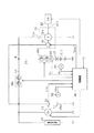
図1に示すように、車載電源システムは、回転電機10、第1蓄電池としての鉛蓄電池11、第2蓄電池としてのリチウムイオン蓄電池12、スタータ13、及び各種の電気負荷14を備えている。鉛蓄電池11は、周知の汎用蓄電池である。一方、リチウムイオン蓄電池12は、鉛蓄電池11と比べて、出力密度及びエネルギ密度が高いものであり、また、頻繁な充放電に対する耐性が高い高性能蓄電池である。本実施形態において、鉛蓄電池11は、その蓄電容量がリチウムイオン蓄電池12の蓄電容量よりも大きくされている。また本実施形態において、鉛蓄電池11は、その定格電圧がリチウムイオン蓄電池12の定格電圧と同一又は略同一とされている。
As shown in FIG. 1, the in-vehicle power supply system includes a rotating
鉛蓄電池11の正極には、接続経路LDを介してリチウムイオン蓄電池12の正極が接続されている。鉛蓄電池11及びリチウムイオン蓄電池12のそれぞれの負極は、接地されている。
The positive electrode of the lithium
回転電機10は、発電部10a、発電制御部10b、及び発電部10aの発電電力を出力する出力部10cを有している。発電部10aは、ステータ、ステータに巻回されたステータコイル、ロータ、及びロータに巻回されたロータコイルを含む。ロータの回転軸は、エンジン20の出力軸20aに対してベルト等により連結されている。本実施形態において回転電機10は、出力軸20aや車軸の回転により発電する発電機として機能する。
The rotating
出力軸20aから供給される動力により、ロータが回転する。発電部10aにおいて、ロータが回転する状況下でロータコイルに流れる励磁電流に応じてステータコイルに交流電流が誘起され、図示しない整流器により直流電流に変換される。そして、ロータコイルに流れる励磁電流が発電制御部10bにより調整されることで、発電された直流電圧が出力電圧指令値Vrefとなるよう調整される。つまり、発電制御部10bは、出力部10cから出力される発電電力を出力電圧指令値Vrefに制御する。発電制御部10bには、鉛蓄電池11から電力が供給される。
The rotor is rotated by the power supplied from the output shaft 20a. In the power generation unit 10a, an alternating current is induced in the stator coil in accordance with the exciting current flowing in the rotor coil under a situation where the rotor rotates, and is converted into a direct current by a rectifier (not shown). The excitation current flowing through the rotor coil is adjusted by the power generation control unit 10b, so that the generated DC voltage is adjusted to the output voltage command value Vref. That is, the power generation control unit 10b controls the generated power output from the
電源システムは、第1スイッチ部SW1と、第2スイッチ部SW2とを備えている。本実施形態において、第1スイッチ部SW1は、接続経路LDに設けられ、閉状態及び開状態のいずれかになることで電気的な導通及び遮断を切り替える半導体スイッチである。本実施形態において、第1スイッチ部SW1は、ソース同士が接続された一対のNチャネルMOSFETにより構成されている。 The power supply system includes a first switch unit SW1 and a second switch unit SW2. In the present embodiment, the first switch unit SW1 is a semiconductor switch that is provided in the connection path LD and switches between electrical continuity and disconnection when in either the closed state or the open state. In the present embodiment, the first switch unit SW1 is configured by a pair of N-channel MOSFETs whose sources are connected to each other.
接続経路LDにおいて第1スイッチ部SW1よりもリチウムイオン蓄電池12側には、出力部10cが電気的に接続されている。接続経路LDにおいて出力部10cとの接続点Nよりもリチウムイオン蓄電池12側には、半導体スイッチである第2スイッチ部SW2が設けられている。本実施形態において、第2スイッチ部SW2は、ソース同士が接続された一対のNチャネルMOSFETにより構成されている。
In the connection path LD, the
鉛蓄電池11には、スタータ13が並列接続されている。スタータ13は、鉛蓄電池11から電力が供給されることにより、エンジン20の出力軸20aに初期回転を付与するクランキングを行う。
A
鉛蓄電池11には、電気負荷14が並列接続されている。電気負荷14には、供給電力の電圧が概ね一定、又は少なくとも所定範囲内で変動するよう安定であることが要求される定電圧要求負荷が含まれる。定電圧要求負荷の具体例としては、ナビゲーション装置、ヘッドライト、及び空調装置の送風ファン等が挙げられる。
An
電源システムは、鉛蓄電池11の端子電圧を検出する第1電圧検出部30と、鉛蓄電池11に流れる充放電電流を検出する第1電流検出部31とを備えている。電源システムは、リチウムイオン蓄電池12の端子電圧を検出する第2電圧検出部32と、リチウムイオン蓄電池12に流れる充放電電流を検出する第2電流検出部33とを備えている。
The power supply system includes a first
各検出部の検出値は、電源システムに備えられる制御装置40に入力される。制御装置40は、エンジン20の始動制御、発電制御部10bに対して出力電圧指令値Vrefを出力する発電制御、並びに鉛蓄電池11及びリチウムイオン蓄電池12の充電率(SOC)が過充放電とならない適正範囲となるよう調整する充放電制御を行う。なお、鉛蓄電池11の適正範囲は、中心となる値から所定範囲に設定され、具体的には例えば90%±2%に設定されている。また、リチウムイオン蓄電池12の適正範囲は、具体的には例えば30〜80%に設定されている。
The detection value of each detection part is input into the
なお、エンジン20の始動制御には、車両ユーザのイグニッションスイッチのオン操作を入力としたエンジン20の初回の始動制御に加えて、アイドリングストップ制御によるエンジン20の再始動制御も含まれる。アイドリングストップ制御とは、周知のとおり所定の自動停止条件の成立によりエンジン20を自動停止させ、その自動停止状態下において所定の再始動条件の成立によりエンジン20を再始動させるものである。
The start control of the
ちなみに、実際には、エンジン20等の車載システムの構成要素のそれぞれに対応して個別に制御装置が設けられる。本実施形態では、制御装置が個別設けられる点が要部ではないため、便宜上、これら制御装置を単一の制御装置40として図示した。
Incidentally, in practice, a control device is provided individually corresponding to each component of the in-vehicle system such as the
続いて、制御装置40により実行されるエンジン20の始動時における充電処理について説明する。
Next, a charging process at the time of starting the
電源システムにおいて、車両が長期間放置され、リチウムイオン蓄電池12が長期間使用されないことがある。この場合、リチウムイオン蓄電池12の自己放電や、リチウムイオン蓄電池12に電気的に接続された機器への暗電流の供給により、リチウムイオン蓄電池12の充電率がその適正範囲の下限値に近くなる又はその下限値を下回る状態である過放電状態となることがある。過放電状態となったリチウムイオン蓄電池12は、その端子電圧が低い状態となり、鉛蓄電池11の端子電圧に対するリチウムイオン蓄電池12の端子電圧の低下度合いが大きい状態となり得る。この状態において、第1スイッチ部SW1が開状態から閉状態に切り替えられると、鉛蓄電池11からリチウムイオン蓄電池12へと過電流が流れるおそれがある。この場合、接続経路LD、鉛蓄電池11及びリチウムイオン蓄電池12等の信頼性が低下するおそれがある。
In the power supply system, the vehicle may be left for a long time, and the lithium
この問題を解決すべく、過放電状態となったリチウムイオン蓄電池12を、新品のリチウムイオン蓄電池や、充電量が十分な中古のリチウムイオン蓄電池に交換することも考えられる。また、過放電状態となったリチウムイオン蓄電池12を車両から取り外し、取り外したリチウムイオン蓄電池12を充電設備で充電して車両に再度搭載することも考えられる。ただし、この場合、交換するための工数が手間となったり、車両ユーザの負担する交換費用が増加したりするといった不都合が生じる。
In order to solve this problem, it is conceivable to replace the lithium
そこで本実施形態では、リチウムイオン蓄電池12が過放電状態になった場合であっても、リチウムイオン蓄電池12を車両から取り外すことなく、リチウムイオン蓄電池12を再度使用可能な状態とする充電処理が行われる。
Therefore, in this embodiment, even when the lithium
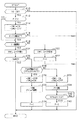
図2に、上記充電処理の手順を示す。この処理は、制御装置40により例えば所定周期で繰り返し実行される。
FIG. 2 shows the procedure of the charging process. This process is repeatedly executed by the
この一連の処理では、まずステップS10において、イグニッションスイッチがオンされているか否かを判定する。ステップS10においてオンされていると判定した場合には、ステップS12に進み、判定フラグFの値が0であるか否かを判定する。判定フラグFは、その初期値が0に設定されている。 In this series of processing, first, in step S10, it is determined whether or not the ignition switch is turned on. If it is determined in step S10 that it is turned on, the process proceeds to step S12 to determine whether or not the value of the determination flag F is zero. The initial value of the determination flag F is set to 0.
ステップS12において判定フラグFの値が0であると判定した場合には、ステップS14に進み、第1スイッチ部SW1を閉状態としてかつ第2スイッチ部SW2を開状態とする。 If it is determined in step S12 that the value of the determination flag F is 0, the process proceeds to step S14, where the first switch unit SW1 is closed and the second switch unit SW2 is opened.
続くステップS16では、エンジン20の始動が完了しているか否かを判定する。なおエンジン20の始動完了を判定する手法としては、例えば、出力軸20aの回転速度が所定回転速度以上になっていると判定した場合に始動が完了したと判定する手法を採用すればよい。なお、エンジン20の始動が完了すると、エンジン20の出力軸20aから供給される動力により、回転電機10による発電が可能となる。本実施形態では、エンジン20が駆動されている状態において、回転電機10の発電電力が発電制御部10bに直接供給される。これにより、発電制御部10bに供給すべき電力を回転電機10の発電電力で賄うことができる。
In a succeeding step S16, it is determined whether or not the
ステップS16においてエンジン20の始動が完了していると判定した場合や、ステップS12において判定フラグFの値が1であると判定した場合には、ステップS18に進む。ステップS18では、リチウムイオン蓄電池12が過放電状態であるか否かを判定する。本実施形態では、第2電圧検出部32により検出されたリチウムイオン蓄電池12の端子電圧VLiが第1判定値Vth1未満であると判定した場合、リチウムイオン蓄電池12が過放電状態であると判定する。本実施形態において、第1判定値Vth1は、リチウムイオン蓄電池12の端子電圧の適正範囲の下限値に設定されている。なお本実施形態において、ステップS18の処理が判定部に相当する。
If it is determined in step S16 that the
なお、図2に示す処理が開始された後、最初にステップS18の処理が行われる場合、第2スイッチ部SW2が開状態とされ、リチウムイオン蓄電池12が接続点Nと切り離されている。このとき、リチウムイオン蓄電池12の開放端電圧が所定値(例えば10V)以下であると判定した場合、リチウムイオン蓄電池12が過放電状態であると判定してもよい。
When the process of step S18 is first performed after the process shown in FIG. 2 is started, the second switch unit SW2 is opened and the lithium
ステップS18において過放電状態でないと判定した場合には、ステップS20に進み、第1スイッチ部SW1及び第2スイッチ部SW2が同時に閉状態とされることを許可する。第1スイッチ部SW1及び第2スイッチ部SW2が閉状態とされている場合において、回転電機10が発電するとき、その発電電力は、鉛蓄電池11、リチウムイオン蓄電池12及び電気負荷14に供給される。ステップS20の処理の完了後、ステップS22に進み、判定フラグFの値を1とする。
If it is determined in step S18 that the overdischarge state is not established, the process proceeds to step S20, where the first switch unit SW1 and the second switch unit SW2 are allowed to be closed simultaneously. When the first switch unit SW1 and the second switch unit SW2 are in the closed state, when the rotating
一方、ステップS18において過放電状態であると判定した場合には、ステップS24に進み、第1スイッチ部SW1及び第2スイッチ部SW2が同時に閉状態とされることを禁止する。なお本実施形態において、ステップS24の処理が禁止部に相当する。 On the other hand, if it is determined in step S18 that the battery is in an overdischarged state, the process proceeds to step S24, and the first switch unit SW1 and the second switch unit SW2 are prohibited from being closed simultaneously. In the present embodiment, the process in step S24 corresponds to a prohibition unit.
続くステップS26では、鉛蓄電池11が劣化しているか否かを判定する。なおステップS26において劣化していると判定した場合、故障警告灯を点灯させること等により、劣化している旨をユーザに通知する処理を行うのが望ましい。
In continuing step S26, it is determined whether the
ステップS26において劣化していないと判定した場合には、ステップS28に進み、鉛蓄電池11の充電量が十分であるか否かを判定する。本実施形態では、第1電圧検出部30により検出された鉛蓄電池11の端子電圧VPbが第2判定値Vth2未満であると判定した場合、鉛蓄電池11の充電量が十分でないと判定する。本実施形態において、第2判定値Vth2は、鉛蓄電池11の端子電圧の適正範囲の下限値に設定されている。なお、鉛蓄電池11の上記下限値は、例えば12.5Vである。
When it determines with having not deteriorated in step S26, it progresses to step S28 and it is determined whether the charge amount of the
ちなみに、鉛蓄電池11の充電量が十分であると判定する方法としては、以下に説明する方法もある。具体的には例えば、鉛蓄電池11を所定電流(例えば5A)で充電しているときの端子電圧が、第2判定値Vth2よりも大きい第3判定値Vth3(例えば14V)以上であると判定した場合、鉛蓄電池11の充電量が十分であると判定する方法がある。また例えば、所定電圧(例えば14V)で充電しているときの鉛蓄電池11への充電電流が所定値(例えば5A)以下であると判定した場合、鉛蓄電池11の充電量が十分であると判定する方法もある。
Incidentally, as a method for determining that the charge amount of the
ステップS28において鉛蓄電池11の充電量が十分であると判定した場合には、ステップS30に進み、第1スイッチ部SW1を開状態としてかつ第2スイッチ部SW2を閉状態とする。
When it determines with the charge amount of the
続くステップS32では、回転電機10の出力部10cから出力される発電電力によりリチウムイオン蓄電池12を充電する。本実施形態では、リチウムイオン蓄電池12の充電時において、出力電圧指令値Vrefが規定値に到達するまで出力電圧指令値Vrefを漸増させる処理を行う。これは、出力部10cからリチウムイオン蓄電池12へと過電流が流れるのを回避するための処理である。なお、上記規定値は、例えば、リチウムイオン蓄電池12及び鉛蓄電池11の定格電圧よりも高い値に設定されている。ステップS32の処理の完了後、続くステップS34では、判定フラグFの値を1とする。
In continuing step S32, the lithium
一方、ステップS28において鉛蓄電池11の充電量が十分でないと判定した場合には、ステップS36に進み、第1スイッチ部SW1を閉状態としてかつ第2スイッチ部SW2を開状態とする。続くステップS38では、回転電機10の出力部10cから出力される発電電力により鉛蓄電池11を充電する。ステップS40では、鉛蓄電池11の端子電圧VPbが、第3判定値Vth3以上になったか否かを判定する。ステップS40において肯定判定した場合には、ステップS42に進み、判定フラグFの値を0とする。
On the other hand, when it determines with the charge amount of the
続いて、図3及び図4を用いて、エンジン20の始動時における上記充電処理についてさらに説明する。
Subsequently, the charging process when the
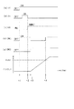
まず、図3を用いて、エンジン20の始動完了時の鉛蓄電池11の充電量が十分である場合の充電処理について説明する。ここで、図3(a)はイグニッションスイッチの操作状態の推移を示し、図3(b)はスタータ13の動作状態の推移を示し、図3(c)はエンジン20の動作状態の推移を示す。図3(d),(e)は第1,第2スイッチ部SW1,SW2の操作状態の推移を示し、図3(f)は第2電圧検出部32により検出されたリチウムイオン蓄電池12の端子電圧VLiの推移を示す。
First, the charging process when the charge amount of the
図示される例では、時刻t1においてイグニッションスイッチがオンされることにより、第1スイッチ部SW1が開状態から閉状態に切り替えられる。その後、スタータ13によりエンジン20の出力軸20aに初期回転が付与され、また、エンジン20の燃焼制御が開始されることにより、時刻t2において、エンジン20の始動が完了したと判定される。なお本実施形態において、鉛蓄電池11は、エンジン20の始動時においてスタータ13の駆動に必要な蓄電量を有していることとする。
In the illustrated example, when the ignition switch is turned on at time t1, the first switch unit SW1 is switched from the open state to the closed state. Thereafter, initial rotation is applied to the output shaft 20a of the
その後、リチウムイオン蓄電池12が過放電状態であると判定されることにより、エンジン20の始動完了後、第1スイッチ部SW1及び第2スイッチ部SW2の双方が閉状態とされるに先立ち、第1スイッチ部SW1及び第2スイッチ部SW2の双方が閉状態とされることが禁止される。
Thereafter, when the lithium
その後時刻t3において、第1スイッチ部SW1が閉状態から開状態に切り替えられ、第2スイッチ部SW2が開状態から閉状態に切り替えられる。そして、回転電機10の発電電力によりリチウムイオン蓄電池12の充電が開始される。リチウムイオン蓄電池12の充電により、時刻t4において、リチウムイオン蓄電池12の端子電圧VLiが第1判定値Vth1に到達したと判定される。このため、リチウムイオン蓄電池12の過放電状態が解消されたと判定され、第1スイッチ部SW1及び第2スイッチ部SW2の双方が閉状態とされることが許可される。これにより、第1スイッチ部SW1が閉状態に切り替えられる。
Thereafter, at time t3, the first switch unit SW1 is switched from the closed state to the open state, and the second switch unit SW2 is switched from the open state to the closed state. Then, charging of the lithium
続いて図4を用いて、エンジン20の始動完了時の鉛蓄電池11の充電量が不十分である場合の充電処理について説明する。なお、図4(a)〜(e),(g)は先の図3(a)〜(f)に対応しており、図4(f)は第1電圧検出部30により検出された鉛蓄電池11の端子電圧VPbの推移を示す。なお図4(f)では、スタータ13の駆動による端子電圧VPbの低下等の図示を省略している。
Next, the charging process when the charge amount of the
図示される例では、時刻t2の後にリチウムイオン蓄電池12が過放電状態であると判定される。その後、リチウムイオン蓄電池12の充電に先立ち、時刻t3において回転電機10の発電電力により鉛蓄電池11の充電が開始される。鉛蓄電池11の充電により、時刻t4において、鉛蓄電池11の端子電圧VPbが第3判定値Vth3に到達したと判定される。その後、鉛蓄電池11の充電量が十分であると判定される。そして、第1スイッチ部SW1が開状態に切り替えられてかつ第2スイッチ部SW2が閉状態に切り替えられた状態で、回転電機10の発電電力によりリチウムイオン蓄電池12の充電が開始される。そして、時刻t5においてリチウムイオン蓄電池12の過放電状態が解消されたと判定され、第1スイッチ部SW1及び第2スイッチ部SW2の双方が閉状態とされることが許可される。これにより、第1スイッチ部SW1が閉状態に切り替えられる。
In the illustrated example, it is determined that the lithium
なお、鉛蓄電池11から電気負荷14への供給電力が大きかったり、リチウムイオン蓄電池12の充電期間が長くなったりする場合には、充電処理によるリチウムイオン蓄電池12の充電中において鉛蓄電池11の端子電圧VPbが第2判定値Vth2未満となり得る。ここで図2に示した充電処理によれば、リチウムイオン蓄電池12の充電中に鉛蓄電池11の端子電圧VPbが第2判定値Vth2未満になったとステップS28の処理で判定された場合、ステップS36の処理により第1スイッチ部SW1が閉状態に切り替えられてかつ第2スイッチ部SW2が開状態に切り替えられた状態とされる。そしてこの状態で、回転電機10の発電電力により鉛蓄電池11が充電され、その後リチウムイオン蓄電池12の充電が再度開始される。このため、リチウムイオン蓄電池12の充電中に鉛蓄電池11から電気負荷14への供給電力が不足することを回避できる。
In addition, when the power supplied from the
以上詳述した本実施形態によれば、以下の効果が得られるようになる。 According to the embodiment described in detail above, the following effects can be obtained.
リチウムイオン蓄電池12が過放電状態であると判定された場合、第1スイッチ部SW1及び第2スイッチ部SW2の双方が閉状態とされることを禁止した。このため、鉛蓄電池11から過放電状態であると判定されたリチウムイオン蓄電池12へと過電流が流れることを回避できる。これにより、電源システムの信頼性の低下を回避できる。
When it was determined that the lithium
リチウムイオン蓄電池12が過放電状態であると判定された場合、第1スイッチ部SW1を開状態としてかつ第2スイッチ部SW2を閉状態とした状態で、回転電機10の発電電力によりリチウムイオン蓄電池12を充電した。このため、過放電状態であると判定されたリチウムイオン蓄電池12を車両から取り外す作業を行うことなく、車両に備えられた状態でリチウムイオン蓄電池12の充電量を増加させ、リチウムイオン蓄電池12を使用可能な状態に復帰させることができる。
When it is determined that the lithium
接続経路LDにおいて第1スイッチ部SW1よりも鉛蓄電池11側に電気負荷14を接続した。このため、過放電状態であると判定されたリチウムイオン蓄電池12の充電時において第1スイッチ部SW1が開状態とされている場合であっても、鉛蓄電池11から電気負荷14へと電力を供給できる。したがって、電気負荷14に供給される電圧が電気負荷14の動作を保証できる最低電圧未満となることを回避しつつ、リチウムイオン蓄電池12の充電処理を行うことができる。
In the connection path LD, the
また、リチウムイオン蓄電池12の充電中に出力電圧指令値Vrefを漸増させる構成において、接続経路LDにおいて第1スイッチ部SW1よりも鉛蓄電池11側に発電制御部10bを接続した。これにより、発電制御部10bに供給される電圧が発電制御部10bの動作を保証できる最低電圧未満となることを回避できる。
Further, in the configuration in which the output voltage command value Vref is gradually increased during charging of the lithium
(その他の実施形態)
なお、上記実施形態は、以下のように変更して実施してもよい。
(Other embodiments)
The above embodiment may be modified as follows.
・リチウムイオン蓄電池12が過放電状態であるか否かの判定手法としては、上記実施形態で説明したものに限らない。例えば、リチウムイオン蓄電池12の充電率がその適正範囲の下限値未満であると判定した場合、リチウムイオン蓄電池12が過放電状態であると判定してもよい。なお、リチウムイオン蓄電池12の充電率は、例えば、第2電流検出部33により検出されたリチウムイオン蓄電池12の充放電電流の積算値に基づいて算出されればよい。
The method for determining whether or not the lithium
また、リチウムイオン蓄電池12が過放電状態であるか否かの判定手法として、例えば、鉛蓄電池11の端子電圧VPb及びリチウムイオン蓄電池12の端子電圧VLiの差に基づく判定手法を用いてもよい。具体的には、鉛蓄電池11の端子電圧VPbからリチウムイオン蓄電池12の端子電圧VLiを減算した値が所定値(>0)未満であると判定した場合、リチウムイオン蓄電池12が過放電状態であると判定すればよい。
Further, as a method for determining whether or not the lithium
さらに、リチウムイオン蓄電池12が過放電状態であるか否かの判定手法としては、端子電圧等の検出値を用いるものに限らない。例えば、電源システムが前回使用されてからの経過時間が所定時間以上になったと判定した場合にリチウムイオン蓄電池12が過放電状態であると判定する手法を用いてもよい。
Furthermore, a method for determining whether or not the lithium
・図2のステップS28において、鉛蓄電池11の充電量が十分であるか否かの判定手法としては、上記実施形態で説明したものに限らない。例えば、鉛蓄電池11の充電率(SOC)がその適正範囲の下限値未満であると判定した場合、鉛蓄電池11の充電量が十分でないと判定してもよい。なお、上記適正範囲の下限値は、例えば88%(=90%−2%)に設定されている。また、鉛蓄電池11の充電率は、例えば、第1電流検出部31により検出された鉛蓄電池11の充放電電流の積算値に基づいて算出されればよい。
-In step S28 of FIG. 2, as a determination method of whether the charge amount of the
・図2のステップS32の処理によりリチウムイオン蓄電池12の充電が行われている期間に実行されるステップS28において、鉛蓄電池11の充電量が十分であると判定するための閾値を、第2判定値Vth2から別の値に切り替えてもよい。具体的には例えば、第2判定値Vth2から、第2判定値Vth2よりも大きくてかつ第3判定値Vth3よりも小さい値に切り替えてもよい。
In step S28 executed during the period when the lithium
・上記実施形態では、第1蓄電池を鉛蓄電池11とし、第2蓄電池をリチウムイオン蓄電池12としたがこれに限らず、第1蓄電池及び第2蓄電池の双方を鉛蓄電池又はリチウムイオン蓄電池にする等、第1蓄電池及び第2蓄電池の双方を同じ種類の蓄電池としてもよい。なお、蓄電池の種類としては、鉛蓄電池及びリチウムイオン蓄電池以外の種類の蓄電池であってもよい。
In the above embodiment, the first storage battery is the
・接続経路LDにおいて第1スイッチ部SW1よりも接続点N側に電気負荷が接続されている構成であってもよい。ここで、接続点N側に接続されている電気負荷としては、例えば、過放電状態のリチウムイオン蓄電池12の充電中に電力が十分に供給されなくてもよい電気負荷や、車両走行に及ぼす影響がない電気負荷、過放電状態のリチウムイオン蓄電池12の充電中に動作しなくてもよい電気負荷などが挙げられる。
-In the connection path | route LD, the structure by which the electrical load is connected to the connection point N side rather than 1st switch part SW1 may be sufficient. Here, as an electrical load connected to the connection point N side, for example, an electrical load that does not require a sufficient supply of power during charging of the lithium
・過放電状態のリチウムイオン蓄電池12を充電する場合において、リチウムイオン蓄電池12の充電電流が所定電流以下になるように出力電圧指令値Vrefを徐々に上昇させてもよい。
-When charging the lithium
・第1スイッチ部SW1及び第2スイッチ部SW2としては、MOSFETにより構成されている半導体スイッチに限らず、例えば、サイリスタにより構成される半導体スイッチや、ソリッドステートリレーを用いてもよい。 The first switch unit SW1 and the second switch unit SW2 are not limited to semiconductor switches configured by MOSFETs, and for example, semiconductor switches configured by thyristors or solid state relays may be used.
10…回転電機、11…鉛蓄電池、12…リチウムイオン蓄電池、40…制御装置、LD…接続経路、SW1…第1スイッチ部、SW2…第2スイッチ部。
DESCRIPTION OF
Claims (8)
第2蓄電池(12)と、
前記第1蓄電池及び前記第2蓄電池を電気的に接続する接続経路(LD)に設けられ、閉状態及び開状態のいずれかになることで電気的な導通及び遮断を切り替える第1スイッチ部(SW1)と、
前記接続経路において前記第1スイッチ部よりも前記第2蓄電池側に電気的に接続された出力部(10c)を有し、該出力部から発電電力を出力する発電機(10)と、
前記接続経路において前記出力部との接続点(N)よりも前記第2蓄電池側に設けられ、閉状態及び開状態のいずれかになることで電気的な導通及び遮断を切り替える第2スイッチ部(SW2)と、を備えるシステムに適用され、
前記第2蓄電池が過放電状態であるか否かを判定する判定部(40)と、
前記判定部により前記第2蓄電池が過放電状態であると判定されていることを条件として、前記第1スイッチ部及び前記第2スイッチ部の双方が閉状態とされることを禁止する禁止部(40)と、を備える電源制御装置。 A first storage battery (11);
A second storage battery (12);
A first switch unit (SW1) that is provided in a connection path (LD) that electrically connects the first storage battery and the second storage battery and switches between electrical continuity and disconnection by being in a closed state or an open state. )When,
A generator (10) having an output part (10c) electrically connected to the second storage battery side from the first switch part in the connection path, and outputting generated power from the output part;
A second switch portion (on the connection path) that is provided closer to the second storage battery than the connection point (N) with the output portion, and switches between electrical continuity and disconnection by being in a closed state or an open state ( SW2), and a system comprising:
A determination unit (40) for determining whether or not the second storage battery is in an overdischarged state;
A prohibition unit that prohibits both the first switch unit and the second switch unit from being closed on the condition that the determination unit determines that the second storage battery is in an overdischarged state ( 40).
前記充電制御部は、前記第2蓄電池の充電時において、前記出力部の出力電圧を徐々に上昇させるものである請求項3に記載の電源制御装置。 The generator is capable of adjusting the output voltage of the output unit,
The power supply control device according to claim 3, wherein the charging control unit gradually increases an output voltage of the output unit during charging of the second storage battery.
前記発電制御部には、前記第1蓄電池から電力が供給される請求項4に記載の電源制御装置。 The generator has a power generation control unit (10b) that adjusts the output voltage of the output unit based on an output voltage command value of the output unit that is instructed by the charge control unit by being supplied with power. ,
The power supply control device according to claim 4, wherein electric power is supplied from the first storage battery to the power generation control unit.
前記発電機は、前記エンジンから動力が供給されることにより発電するものであり、
前記発電機は、給電されることにより、前記充電制御部から指示される前記出力部の出力電圧指令値に基づいて前記出力部の出力電圧を調節する発電制御部(10b)を有しており、
前記発電制御部には、前記エンジンが駆動されている状態において、前記発電機から電力が供給される請求項4又は5に記載の電源制御装置。 The system includes an engine (20),
The generator generates power when power is supplied from the engine,
The generator has a power generation control unit (10b) that adjusts the output voltage of the output unit based on an output voltage command value of the output unit that is instructed by the charge control unit by being supplied with power. ,
The power supply control device according to claim 4 or 5, wherein the power generation control unit is supplied with electric power from the generator in a state where the engine is driven.
Priority Applications (3)
| Application Number | Priority Date | Filing Date | Title |
|---|---|---|---|
| JP2016091347A JP2017197117A (en) | 2016-04-28 | 2016-04-28 | Power supply controller |
| CN201780026020.8A CN109070819A (en) | 2016-04-28 | 2017-04-21 | Power control |
| PCT/JP2017/016121 WO2017188163A1 (en) | 2016-04-28 | 2017-04-21 | Power source controller |
Applications Claiming Priority (1)
| Application Number | Priority Date | Filing Date | Title |
|---|---|---|---|
| JP2016091347A JP2017197117A (en) | 2016-04-28 | 2016-04-28 | Power supply controller |
Publications (2)
| Publication Number | Publication Date |
|---|---|
| JP2017197117A true JP2017197117A (en) | 2017-11-02 |
| JP2017197117A5 JP2017197117A5 (en) | 2018-03-29 |
Family
ID=60161521
Family Applications (1)
| Application Number | Title | Priority Date | Filing Date |
|---|---|---|---|
| JP2016091347A Pending JP2017197117A (en) | 2016-04-28 | 2016-04-28 | Power supply controller |
Country Status (3)
| Country | Link |
|---|---|
| JP (1) | JP2017197117A (en) |
| CN (1) | CN109070819A (en) |
| WO (1) | WO2017188163A1 (en) |
Cited By (1)
| Publication number | Priority date | Publication date | Assignee | Title |
|---|---|---|---|---|
| KR20220090206A (en) * | 2020-12-22 | 2022-06-29 | 경북대학교 산학협력단 | Device and method for preventing battery abnormalities using diodes |
Families Citing this family (3)
| Publication number | Priority date | Publication date | Assignee | Title |
|---|---|---|---|---|
| JP7326905B2 (en) * | 2019-06-17 | 2023-08-16 | 株式会社デンソー | Control device |
| JP7342801B2 (en) | 2020-06-10 | 2023-09-12 | 株式会社デンソー | power control device |
| SE545638C2 (en) * | 2022-02-17 | 2023-11-21 | Man Truck & Bus Se | A power supply circuit and a method for controlling a power supply circuit |
Citations (5)
| Publication number | Priority date | Publication date | Assignee | Title |
|---|---|---|---|---|
| JP2004025979A (en) * | 2002-06-25 | 2004-01-29 | Shin Kobe Electric Mach Co Ltd | Power supply system for travelling vehicle |
| JP2004289889A (en) * | 2003-03-19 | 2004-10-14 | Matsushita Electric Ind Co Ltd | Charging apparatus and electronic equipment |
| JP2005080318A (en) * | 2003-08-29 | 2005-03-24 | Fuji Electric Holdings Co Ltd | Method for controlling charging/discharging of battery and charging control device |
| JP2009044318A (en) * | 2007-08-07 | 2009-02-26 | Auto Network Gijutsu Kenkyusho:Kk | On-board communication system and distribution apparatus |
| JP2015204699A (en) * | 2014-04-15 | 2015-11-16 | 株式会社デンソー | battery unit |
-
2016
- 2016-04-28 JP JP2016091347A patent/JP2017197117A/en active Pending
-
2017
- 2017-04-21 WO PCT/JP2017/016121 patent/WO2017188163A1/en active Application Filing
- 2017-04-21 CN CN201780026020.8A patent/CN109070819A/en not_active Withdrawn
Patent Citations (5)
| Publication number | Priority date | Publication date | Assignee | Title |
|---|---|---|---|---|
| JP2004025979A (en) * | 2002-06-25 | 2004-01-29 | Shin Kobe Electric Mach Co Ltd | Power supply system for travelling vehicle |
| JP2004289889A (en) * | 2003-03-19 | 2004-10-14 | Matsushita Electric Ind Co Ltd | Charging apparatus and electronic equipment |
| JP2005080318A (en) * | 2003-08-29 | 2005-03-24 | Fuji Electric Holdings Co Ltd | Method for controlling charging/discharging of battery and charging control device |
| JP2009044318A (en) * | 2007-08-07 | 2009-02-26 | Auto Network Gijutsu Kenkyusho:Kk | On-board communication system and distribution apparatus |
| JP2015204699A (en) * | 2014-04-15 | 2015-11-16 | 株式会社デンソー | battery unit |
Cited By (2)
| Publication number | Priority date | Publication date | Assignee | Title |
|---|---|---|---|---|
| KR20220090206A (en) * | 2020-12-22 | 2022-06-29 | 경북대학교 산학협력단 | Device and method for preventing battery abnormalities using diodes |
| KR102538244B1 (en) * | 2020-12-22 | 2023-05-30 | 경북대학교 산학협력단 | Device and method for preventing battery abnormalities using diodes |
Also Published As
| Publication number | Publication date |
|---|---|
| WO2017188163A1 (en) | 2017-11-02 |
| CN109070819A (en) | 2018-12-21 |
Similar Documents
| Publication | Publication Date | Title |
|---|---|---|
| CN105936248B (en) | Power supply system | |
| US9649950B2 (en) | Power supply apparatus | |
| RU2592468C1 (en) | Power supply control device | |
| JP6613997B2 (en) | Power supply | |
| JP5889750B2 (en) | Vehicle power supply system | |
| JP5846073B2 (en) | Power system | |
| US20140232302A1 (en) | Battery processing apparatus, vehicle, battery processing method, and battery processing program | |
| JP5884674B2 (en) | Vehicle power supply system | |
| JP5924418B2 (en) | Power storage system | |
| JP6119725B2 (en) | Charger | |
| WO2017188163A1 (en) | Power source controller | |
| US10498154B2 (en) | Electric power system | |
| JP5965775B2 (en) | Vehicle power system | |
| JP6481483B2 (en) | Power supply | |
| JP2017221086A (en) | On-vehicle power supply system | |
| JP2005117722A (en) | Charge/discharge control device of battery pack | |
| JP6825253B2 (en) | Control device and power supply system | |
| JP2013252017A (en) | Power supply control method and device for vehicle | |
| JP5796545B2 (en) | Power system | |
| JP6801367B2 (en) | Vehicle power supply system control method and vehicle power supply system | |
| WO2017191818A1 (en) | Power supply device | |
| JP7111044B2 (en) | Control device | |
| JP2018007478A (en) | Power supply controller and power supply system | |
| JP6488995B2 (en) | Control device for in-vehicle power supply system | |
| JP6936683B2 (en) | Vehicle power supply system and vehicle power supply system control device |
Legal Events
| Date | Code | Title | Description |
|---|---|---|---|
| A521 | Request for written amendment filed |
Free format text: JAPANESE INTERMEDIATE CODE: A523 Effective date: 20180215 |
|
| A621 | Written request for application examination |
Free format text: JAPANESE INTERMEDIATE CODE: A621 Effective date: 20180215 |
|
| A131 | Notification of reasons for refusal |
Free format text: JAPANESE INTERMEDIATE CODE: A131 Effective date: 20190416 |
|
| A02 | Decision of refusal |
Free format text: JAPANESE INTERMEDIATE CODE: A02 Effective date: 20191119 |