JP2017196676A - Joint mechanism having cable - Google Patents
Joint mechanism having cable Download PDFInfo
- Publication number
- JP2017196676A JP2017196676A JP2016087478A JP2016087478A JP2017196676A JP 2017196676 A JP2017196676 A JP 2017196676A JP 2016087478 A JP2016087478 A JP 2016087478A JP 2016087478 A JP2016087478 A JP 2016087478A JP 2017196676 A JP2017196676 A JP 2017196676A
- Authority
- JP
- Japan
- Prior art keywords
- link
- optical fiber
- core wire
- joint
- cable
- Prior art date
- Legal status (The legal status is an assumption and is not a legal conclusion. Google has not performed a legal analysis and makes no representation as to the accuracy of the status listed.)
- Granted
Links
Images


Classifications
-
- B—PERFORMING OPERATIONS; TRANSPORTING
- B25—HAND TOOLS; PORTABLE POWER-DRIVEN TOOLS; MANIPULATORS
- B25J—MANIPULATORS; CHAMBERS PROVIDED WITH MANIPULATION DEVICES
- B25J19/00—Accessories fitted to manipulators, e.g. for monitoring, for viewing; Safety devices combined with or specially adapted for use in connection with manipulators
- B25J19/0025—Means for supplying energy to the end effector
- B25J19/0029—Means for supplying energy to the end effector arranged within the different robot elements
-
- B—PERFORMING OPERATIONS; TRANSPORTING
- B25—HAND TOOLS; PORTABLE POWER-DRIVEN TOOLS; MANIPULATORS
- B25J—MANIPULATORS; CHAMBERS PROVIDED WITH MANIPULATION DEVICES
- B25J19/00—Accessories fitted to manipulators, e.g. for monitoring, for viewing; Safety devices combined with or specially adapted for use in connection with manipulators
-
- B—PERFORMING OPERATIONS; TRANSPORTING
- B25—HAND TOOLS; PORTABLE POWER-DRIVEN TOOLS; MANIPULATORS
- B25J—MANIPULATORS; CHAMBERS PROVIDED WITH MANIPULATION DEVICES
- B25J17/00—Joints
-
- B—PERFORMING OPERATIONS; TRANSPORTING
- B25—HAND TOOLS; PORTABLE POWER-DRIVEN TOOLS; MANIPULATORS
- B25J—MANIPULATORS; CHAMBERS PROVIDED WITH MANIPULATION DEVICES
- B25J17/00—Joints
- B25J17/02—Wrist joints
-
- G—PHYSICS
- G02—OPTICS
- G02B—OPTICAL ELEMENTS, SYSTEMS OR APPARATUS
- G02B6/00—Light guides; Structural details of arrangements comprising light guides and other optical elements, e.g. couplings
- G02B6/24—Coupling light guides
- G02B6/42—Coupling light guides with opto-electronic elements
- G02B6/4201—Packages, e.g. shape, construction, internal or external details
- G02B6/4256—Details of housings
-
- G—PHYSICS
- G02—OPTICS
- G02B—OPTICAL ELEMENTS, SYSTEMS OR APPARATUS
- G02B6/00—Light guides; Structural details of arrangements comprising light guides and other optical elements, e.g. couplings
- G02B6/44—Mechanical structures for providing tensile strength and external protection for fibres, e.g. optical transmission cables
- G02B6/4401—Optical cables
- G02B6/4429—Means specially adapted for strengthening or protecting the cables
- G02B6/443—Protective covering
-
- Y—GENERAL TAGGING OF NEW TECHNOLOGICAL DEVELOPMENTS; GENERAL TAGGING OF CROSS-SECTIONAL TECHNOLOGIES SPANNING OVER SEVERAL SECTIONS OF THE IPC; TECHNICAL SUBJECTS COVERED BY FORMER USPC CROSS-REFERENCE ART COLLECTIONS [XRACs] AND DIGESTS
- Y10—TECHNICAL SUBJECTS COVERED BY FORMER USPC
- Y10S—TECHNICAL SUBJECTS COVERED BY FORMER USPC CROSS-REFERENCE ART COLLECTIONS [XRACs] AND DIGESTS
- Y10S901/00—Robots
- Y10S901/27—Arm part
- Y10S901/28—Joint
Abstract
Description
本発明は、ロボット内部に敷設されたケーブルを備える関節機構に関する。 The present invention relates to a joint mechanism including a cable laid inside a robot.
ロボットの姿勢を高速に且つノイズを受けずに制御するため、2つのリンクを連結する関節部の回動軸上に光送信装置と光受信装置とを設け、光送信装置と光受信装置との間に光ファイバケーブルを敷設し、光送信装置と光受信装置との間で光信号の伝送を行うロボットが開示されている(例えば、特許文献1)。 In order to control the posture of the robot at high speed and without receiving noise, an optical transmission device and an optical reception device are provided on the rotation axis of the joint portion connecting the two links, and the optical transmission device and the optical reception device A robot is disclosed in which an optical fiber cable is laid between the optical transmitter and the optical receiver to transmit an optical signal (for example, Patent Document 1).
ところで、複数の関節部を備えるロボットでは、複数の関節部を介して接続された複数のリンクにそれぞれ関節制御装置を設け、それら複数の関節制御装置を連動させることによって、ロボットの姿勢制御が行われるようになっている。しかしながら、互いに複数の関節を介して接続されたリンク上の関節制御装置間に光信号を伝送させるためには、関節制御装置間に設けられた関節部の全ての回動軸に光送信装置と光受信装置とを設けて中継する必要がある。一方、回動軸から外れた位置、又は、複数の関節を介して接続された2つのリンク上にそれぞれ光送信装置と光受信装置とを設け、ケーブルによって光送信装置と光受信装置とを接続すると、ケーブルは関節部において、屈設されるため、関節部の屈曲によってケーブルが破損する虞があった。 By the way, in a robot having a plurality of joint portions, a joint control device is provided for each of a plurality of links connected via the plurality of joint portions, and the posture control of the robot is performed by interlocking the plurality of joint control devices. It has come to be. However, in order to transmit an optical signal between joint control devices on a link connected to each other via a plurality of joints, an optical transmission device is connected to all the rotation shafts of the joint portions provided between the joint control devices. It is necessary to provide an optical receiver and relay. On the other hand, an optical transmission device and an optical reception device are respectively provided on a position deviated from the rotation axis or on two links connected through a plurality of joints, and the optical transmission device and the optical reception device are connected by a cable. Then, since the cable is bent at the joint portion, there is a possibility that the cable may be damaged due to the bending of the joint portion.
本発明は、このような背景に鑑み、光ファイバケーブルを備える関節部において、ケーブルが使用時の屈曲によって断線や損傷を受ける虞の少ない関節機構を提供することを課題とする。 In view of such a background, it is an object of the present invention to provide a joint mechanism in which a cable is less likely to be disconnected or damaged due to bending during use in a joint portion including an optical fiber cable.
上記課題を解決するために、ケーブルを備える関節機構(101、201、301、401)が、関節(KR、ER、MR、UR)を介して互いに変位可能に連結され、それぞれ信号送受信装置(LO2、LO3、AO1、AO2、MO1、MO2、UO1、UO2)を備える第1リンク(L1、A1、M1、U1)及び第2リンク(L2、A2、M2、U2)と、前記第1リンクの前記信号送受信装置と前記第2リンクの前記信号送受信装置とを繋ぐように敷設されるケーブル(F1、F2、F3、F4)と、前記第1リンク及び前記第2リンクのそれぞれに関節から離れた位置に設けられ、前記ケーブルを対応するリンクに保持する芯線保持部(P1〜P8)と、前記第1リンク及び前記第2リンクのそれぞれの前記芯線保持部よりも前記関節に近い位置に設けられ、前記ケーブルを対応するリンクに所定の範囲で移動可能に係止する芯線係止部(Q1〜Q10)を備えるとよい。 In order to solve the above problems, joint mechanisms (101, 201, 301, 401) including cables are connected to each other via joints (K R , E R , M R , U R ) so as to be displaceable from each other. A first link (L1, A1, M1, U1) and a second link (L2, A2, M2, U2) including transmission / reception devices (LO2, LO3, AO1, AO2, MO1, MO2, UO1, UO2); A cable (F1, F2, F3, F4) laid to connect the signal transmitting / receiving device of one link and the signal transmitting / receiving device of the second link, and a joint to each of the first link and the second link A core wire holding portion (P1 to P8) that is provided at a position away from the core and holds the cable on the corresponding link, and the core wire holding portion of each of the first link and the second link. Also provided at a position closer to the joint, may comprise corresponding wire engaging portion for movably engaging in a predetermined range link (Q1 to Q10) of said cable.
ここで関節を介して互いに変位可能に連結されるとは、第1リンクと第2リンクとが1軸回動可能に連結する連結軸によって直接連結される場合と他のリンクを介して間接的に連結される場合とを含む。 Here, being connected to each other via a joint so as to be displaceable means that the first link and the second link are directly connected by a connecting shaft that is connected so as to be rotatable about one axis and indirectly through another link. Connected to
この態様によれば、ケーブルが芯線保持部においてリンクに保持され、芯線保持部よりも関節機構に近い位置に設けられた芯線係止部において、ケーブルが所定の範囲で移動可能にリンクに係止される。ケーブルが関節機構に備えられたリンクに保持されつつ、ケーブルが関節部での屈曲に応じて移動可能であるように係止されるため、関節部での屈曲によってケーブルが受ける荷重を緩和することが可能となる。 According to this aspect, the cable is held by the link in the core wire holding portion, and the cable is locked to the link so that the cable can move within a predetermined range in the core wire locking portion provided at a position closer to the joint mechanism than the core wire holding portion. Is done. While the cable is held by the link provided in the joint mechanism, the cable is locked so that it can move according to the bending at the joint, so the load applied to the cable by the bending at the joint is reduced. Is possible.
また、上記ケーブルを備える関節機構(201)において、前記芯線係止部(Q11、Q14)が、前記第1リンク(A1)及び前記第2リンク(A2)にそれぞれ複数設けられるとよい。 In the joint mechanism (201) including the cable, a plurality of the core wire locking portions (Q11, Q14) may be provided on each of the first link (A1) and the second link (A2).
この態様によれば、ケーブルが複数の芯線係止部によって係止され、ケーブルをよりリンクに沿って敷設することが可能となる。 According to this aspect, the cable is locked by the plurality of core wire locking portions, and the cable can be laid along the link more.
また、上記ケーブルを備える関節機構(101、201、301、401)において、ケーブル芯線(11、21、31)が光ファイバ芯線(F1、F2、F3、F4)であり、前記信号送受信装置が光送受信装置(LO2、LO3、AO1、AO2、MO1、MO2、UO1、UO2)であって、前記ケーブルが前記光ファイバ芯線を前記光ファイバ芯線の軸線に直交する方向へ所定の範囲で移動可能に被覆する被覆材(C1、C2、C3、C4)とを有する光ファイバケーブルであって、前記芯線係止部(Q1〜Q14)が前記被覆材を前記リンクに固定する被覆材固定部(Q1−2、Q2−2)を含むとよい。 In the joint mechanism (101, 201, 301, 401) including the cable, the cable core wires (11, 21, 31) are optical fiber core wires (F1, F2, F3, F4), and the signal transmitting / receiving device is an optical fiber. Transmitter / receiver (LO2, LO3, AO1, AO2, MO1, MO2, UO1, UO2), wherein the cable covers the optical fiber core wire in a predetermined range in a direction perpendicular to the axis of the optical fiber core wire dressing for (C1, C2, C3, C4 ) and an optical fiber cable having a coating material fixed part (Q1 -2 to the core wire locking portion (Q1 to Q14) secures the dressing to the link , it may include a Q2 -2).
この態様によれば、ケーブルが光ファイバケーブルであり、信号送受信装置が光送受信装置であって、被覆材固定部によって被覆材がリンクに固定され、リンクに固定された被覆材によって光ファイバケーブルの軸線に直交する方向への移動が規制される。光ファイバ芯線をリンクに所定の範囲で移動可能に係止する構成が被覆材及び被覆材固定部による簡単な構成で実現される。 According to this aspect, the cable is an optical fiber cable, the signal transmission / reception device is an optical transmission / reception device, the covering material is fixed to the link by the covering material fixing portion, and the optical fiber cable is fixed by the covering material fixed to the link. Movement in a direction perpendicular to the axis is restricted. A configuration in which the optical fiber core wire is locked to the link so as to be movable within a predetermined range is realized by a simple configuration using the coating material and the coating material fixing portion.
また、上記芯線保持部(P1〜P8)が前記光ファイバ芯線(F1、F2、F3、F4)を前記被覆材(C1、C2、C3、C4)に固定する芯線固定部(P1−1、P2−1)と前記被覆材を前記リンクに固定する被覆材固定部(P1−2、P2−2)とを含むとよい。 Further, the core wire holding portion (P1 to P8) the optical fiber core wire (F1, F2, F3, F4 ) the coating material of (C1, C2, C3, C4 ) to the fixed core fixed part (P1 -1, P2 -1) and the covering member fixing portion for fixing the dressing to the link (P1 -2, may include a P2 -2) and.
この態様によれば、芯線固定部によって、光ファイバ芯線が被覆材に固定され、被覆材固定部によって、被覆材がリンクに固定される。光ファイバ芯線をリンクに固定し保持する構成が芯線固定部及び被覆材固定部による簡単な構成によって実現される。 According to this aspect, the optical fiber core wire is fixed to the covering material by the core wire fixing portion, and the covering material is fixed to the link by the covering material fixing portion. A configuration for fixing and holding the optical fiber core wire to the link is realized by a simple configuration using the core wire fixing portion and the covering material fixing portion.
また、上記光ファイバ芯線(F1、F2、F3、F4)の許容曲げ半径が前記被覆材の許容曲げ半径よりも小さいとよい。 The allowable bending radius of the optical fiber core wires (F1, F2, F3, F4) may be smaller than the allowable bending radius of the covering material.
この態様によれば、関節部におけるケーブルの曲げ半径が被覆材の許容曲げ半径よりも小さく光ファイバケーブルの許容曲げ半径よりも大きい時に、光ファイバ芯線は破損せず被覆材のみが破損しうるため、被覆材の破損によってケーブルの曲げ半径の小さい箇所を同定することが可能となる。 According to this aspect, when the bending radius of the cable at the joint is smaller than the allowable bending radius of the covering material and larger than the allowable bending radius of the optical fiber cable, the optical fiber core wire is not damaged and only the covering material can be damaged. It is possible to identify a portion having a small bending radius of the cable due to breakage of the covering material.
上記関節(KR)が前記第2リンク(L2)を前記第1リンク(L1)に対して1つの回動軸を中心とする回動可能に前記第1リンクに連結する連結部(KR1)によって構成され、前記連結部が前記回動軸に沿って設けられた内孔(13)を備える回動軸部材(12)を有し、前記光ファイバケーブル(11)が前記内孔を通るように敷設されるとよい。 The joint (K R) is connecting portion connecting to one pivotally said first link about the pivot axis relative to the second link (L2) of said first link (L1) (K R1 ), And the connecting portion has a rotating shaft member (12) having an inner hole (13) provided along the rotating shaft, and the optical fiber cable (11) passes through the inner hole. It is good to be laid.
この態様によれば、光ファイバケーブルが連結部の回動軸に沿って敷設される。 According to this aspect, the optical fiber cable is laid along the rotation axis of the connecting portion.
また、上記第1リンク(A1)と前記第2リンク(A2)との間に連結される少なくとも1つの中間リンク(E)を備え、前記第1リンクは、リンクを互いに1軸に回動可能に連結する連結部(ER1、ER2)を介して順番に第2リンクにまで連結され、前記ケーブル(21)が第1リンクから順番に設けられた連結部を介して第2リンクに接続され、前記中間リンクのそれぞれに前記芯線係止部(Q4、Q5)が少なくとも2つ設けられるとよい。 In addition, at least one intermediate link (E) connected between the first link (A1) and the second link (A2) is provided, and the first link is capable of rotating the link around one axis. Are connected to the second link in order via connecting parts (E R1 , E R2 ) connected to the cable, and the cable (21) is connected to the second link via a connecting part provided in order from the first link. In addition, it is preferable that at least two core wire locking portions (Q4, Q5) are provided in each of the intermediate links.
この態様によれば、光ファイバ芯線を第1リンク及び第2リンクの間に連結された中間リンクに係止することが可能となる。 According to this aspect, the optical fiber core line can be locked to the intermediate link connected between the first link and the second link.
上記連結部(ER1、ER2)の全てが前記回動軸に沿って設けられた内孔(24、25)を備える回動軸部材(22、23)を有し、前記光ファイバケーブルが全ての前記内孔を通るように敷設されるとよい。 All of the connecting portions (E R1 , E R2 ) have rotating shaft members (22, 23) having inner holes (24, 25) provided along the rotating shaft, and the optical fiber cable is It is good to lay through all the said inner holes.
この態様によれば、関節に設けられた連結部において、光ファイバケーブルが全ての連結部の回動軸に沿って敷設される。 According to this aspect, the optical fiber cables are laid along the rotation axes of all the connecting portions in the connecting portion provided in the joint.
また、上記関節(MR)が前記第1リンク(M1)に対して、前記第2リンク(M2)を並進変位させるように連結するとよい。 The joint (M R ) may be connected to the first link (M1) so as to translate the second link (M2).
この態様によれば、ケーブルを互いに並進変位する2つリンクを備える関節に敷設することが可能となる。 According to this aspect, the cable can be laid on a joint having two links that are displaced in translation relative to each other.
また、上記関節(UR)が前記第1リンク(U1)に対して前記第2リンク(U2)をねじれ変位させるように連結するとよい。 Further, the joint (U R ) may be connected so as to displace the second link (U2) relative to the first link (U1).
この態様によれば、ケーブルを互いにねじれ変位する2つリンクを備える関節に敷設することが可能となる。 According to this aspect, the cable can be laid at a joint including two links that are twisted and displaced with respect to each other.
また、上記光ファイバケーブル(11、21、31)が複数の光ファイバ芯線(F1、F2、F3)を備えるとよい。 The optical fiber cable (11, 21, 31) may include a plurality of optical fiber core wires (F1, F2, F3).
この態様によれば、光ファイバケーブルに備えられた複数の光ファイバ芯線を用いて複数の信号を伝送することが可能となる。 According to this aspect, it is possible to transmit a plurality of signals using the plurality of optical fiber core wires provided in the optical fiber cable.
以上の構成によれば、光ファイバケーブルを備える関節において、ケーブルが使用時の屈曲によって断線や損傷を受ける虞の少ない関節機構を構成することが可能となる。 According to the above configuration, in a joint provided with an optical fiber cable, it is possible to configure a joint mechanism that is less likely to be disconnected or damaged due to bending of the cable during use.
以下、図面を参照して、本発明を実施形態に係るロボットRについて、図面を参照して説明する。 Hereinafter, a robot R according to an embodiment of the present invention will be described with reference to the drawings.
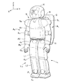
図1に示されるように、ロボットRは、自律的に歩行・走行を行う2脚歩行式ロボットである。以下の説明において、ロボットRの前後方向をX軸、左右方向をY軸、上下方向をZ軸とする。ロボットRは、頭部H、2本の腕部AL及びAR、上体部B及び2本の脚部LL及びLRを備える。頭部HはロボットRの基体部である上体部Bに首関節部Nを介して連結されている。上体部Bの左側には、肩関節部SLを介して腕部ALが連結されている。上体部Bの右側には、肩関節部SRを介して腕部ARが連結されている。上体部Bの下面左側に股関節部JLを介して脚部LLが連結されている。上体部Bの下面右側に、股関節部JRを介して脚部LRが連結されている。上体部Bの背面には、頭部H、上体部B、腕部AL、AR及び脚部LL、LRの制御を行うための制御装置搭載部Cが設けられている。 As shown in FIG. 1, the robot R is a biped walking robot that autonomously walks and runs. In the following description, the front-rear direction of the robot R is the X axis, the left-right direction is the Y-axis, and the up-down direction is the Z-axis. The robot R includes a head H, two arm portions A L and A R , an upper body portion B, and two leg portions L L and L R. The head H is connected to an upper body B which is a base body of the robot R via a neck joint N. On the left side of the body portion B, arms A L through the shoulder joints S L is connected. On the right side of the body portion B, arms A R through the shoulder joints S R is connected. The leg portion L L is connected to the lower surface left side of the upper body portion B through the hip joint portion J L. A leg portion LR is connected to the lower right side of the upper body portion B via a hip joint portion JR . On the back surface of the upper body part B, a control device mounting part C for controlling the head H, the upper body part B, the arm parts A L and A R and the leg parts L L and L R is provided.
脚部LRはリンクL1をその上部に備え、リンクL1の上端が股関節部JRを介して上体部Bの下端右側に連結している。膝関節部KRがリンクL1の下端に設けられており、リンクL1が膝関節部KRを介してリンクL2と連結している。リンクL2の下端には、足首関節部FRを介して、地面に当接する足部IRが備えられている。 The legs L R comprises a link L1 thereon, the upper end of the link L1 is connected through the hip J R in the lower end right side of the body portion B. Knee joint K R is provided at the lower end of the link L1, the link L1 is connected to the link L2 through a knee joint K R. The lower end of link L2, via the ankle joint unit F R, contacting foot I R is provided on the ground.
腕部ARはその上部にリンクA1を備え、リンクA1の上端は肩関節部SRを介して上体部Bの上部右側に連結している。リンクA1の下端に肘関節部ERが設けられており、リンクA1は肘関節部ERを介してリンクA2と連結している。リンクA2の下端に、物品を把持するために人の手の形状とされた把持部GRが手首関節部WRを介して設けられている。 Arms A R includes a link A1 thereon, the upper end of the link A1 is via the shoulder joints S R is connected to the upper right side of the body portion B. And elbow joint E R is provided at the lower end of the link A1, it links A1 is connected to the link A2 through the elbow joint E R. The lower end of the link A2, the gripping portion G R which is the shape of a person's hand to grip the article is provided via the wrist joints W R.
図2に示されるように、ロボットRの内部には、リンクと関節部内部に設けられ隣接配置された一対のリンクを連結する連結部とが複数設けられている。連結部は一方のリンクに対して他方のリンクを1軸に回動可能に連結している。連結部の回動方向は、X軸を中心とする回転(ロール)、Y軸を中心とする回転(ピッチ)、Z軸を中心とする回転(ヨー)の3種から成り、それらの組み合わせによって関節部における複数の自由度を有する回動が可能となる。ロボットRを構成するリンク上には姿勢制御に用いるための光信号を送受信する光送受信モジュールが複数設けられており、光送受信モジュールLO1、LO2、AO1、AO2が関節部を通る光ファイバケーブル11、21によって接続される。
As shown in FIG. 2, the robot R includes a plurality of links and a connecting portion that is provided inside the joint and connects a pair of adjacent links. The connecting portion is connected to one link so that the other link is rotatable about one axis. The rotation direction of the connecting portion consists of three types of rotation around the X axis (roll), rotation around the Y axis (pitch), and rotation around the Z axis (yaw). The joint portion can be rotated with a plurality of degrees of freedom. A plurality of optical transmission / reception modules that transmit and receive optical signals for use in posture control are provided on the link constituting the robot R, and the optical transmission / reception modules LO1, LO2, AO1, and AO2 are
ロボットRに設けられた光送受信モジュールLO1、LO2、AO1、AO2が関節部を通る光ファイバケーブル11、21によって接続され、光ファイバケーブル11、21はロボットRに設けられたリング型トポロジを有する光ファイバネットワークの一部を構成する。図2に示されるようにロボットRには腕部や脚部等に直列に接続された複数のリンクを備える。ロボットRの光ファイバネットワークは直列に接続されたリンク上の光送受信モジュールを順番に接続するリング型トポロジを有し、光ファイバネットワークが関節部を通過する光ファイバケーブルを一端側から他端側へ及び他端側から一端側へ接続された光ファイバケーブルによって構成されている。直列に接続された3つ以上のリンクに設けられた光送受信モジュールを光ファイバケーブルによって接続することによってリング型トポロジを有する光ファイバネットワークを構成すると、関節部を通過する光ファイバケーブルは送信受信の2本となる。一方、直列に接続された3つ以上のリンクにおいてリンクの一端側に設けられネットワークのハブとなる光送受信モジュールと他の光送受信モジュール全てとが送信受信の2本の光ファイバケーブルによって接続されることによって放射型トポロジを有する光ファイバネットワークを構成すると、リング型トポロジを有する光ファイバネットワークに比べて放射型トポロジを有する光ファイバネットワークではハブ側の関節部に多数の光ファイバケーブルが設けられる。リング型トポロジは放射型トポロジに比べ、関節部に設けられる光ファイバケーブルの本数が少なくなるため、リング状トポロジを有する光ファイバネットワークでは光ファイバケーブルを回動軸に沿って設けることがより容易になる。
Optical transmission / reception modules LO1, LO2, AO1, and AO2 provided in the robot R are connected by
脚部LRは、股関節部JRを介して、上体部Bの下端に接続されている。股関節部JRにはX軸、Y軸及びZ軸回りの3軸の回動を各々可能とする3つの連結部JR1、JR2及びJR3が備えられている。股関節部JRの下端に設けられた連結部JR3に、リンクL1が連結されている。リンクL1の下端に膝関節部KRが設けられ、リンクL1は膝関節部KRを介してリンクL2に連結している。膝関節部KRにリンクL2をリンクL1に対してY軸回りに回動可能に連結する連結部KR1が備えられている。リンクL1の上部には光送受信モジュールLO1が設けられ、リンクL1の下部に光送受信モジュールLO2が備えられている。リンクL2の下部には光送受信モジュールLO3が備えられている。 The leg part LR is connected to the lower end of the upper body part B via the hip joint part JR . The hip joint portion JR is provided with three connecting portions J R1 , J R2, and J R3 that can rotate around three axes around the X, Y, and Z axes. A link L1 is connected to a connecting portion JR3 provided at the lower end of the hip joint JR . Knee joint K R is provided at the lower end of the link L1, the link L1 is connected to the link L2 through a knee joint K R. Coupling portion K R1 for rotatably connected to the Y-axis relative to the link L1 to link L2 to the knee joint K R is provided. An optical transmission / reception module LO1 is provided above the link L1, and an optical transmission / reception module LO2 is provided below the link L1. An optical transmission / reception module LO3 is provided below the link L2.
腕部ARはその上端にリンクA1を備え、リンクA1の上端は肩関節部SRを介して上体部Bの上部右端に連結される。リンクA1の下端に肘関節部ERが設けられ、リンクA1は肘関節部ERを介してリンクA2の上端に接続している。肘関節部ERにリンクA1側から順番にリンクEをリンクA1に対してY軸回りの回動可能に連結する連結部ER1と、連結部ER1に接続されたリンクEと、リンクEに連結され、リンクA2をリンクEに対してX軸回りの回動可能に連結する連結部ER2とが設けられている。リンクA1には、光送受信モジュールAO1が設けられ、リンクA2の上端には光送受信モジュールAO2が備えられている。 Arms A R includes a link A1 at its upper end, the upper end of the link A1 is connected to the upper right end of the body portion B through the shoulder joints S R. Provided the elbow joint E R at the lower end of the link A1 is, it links A1 is connected to the upper end of the link A2 through the elbow joint E R. A connecting portion E R1 for connecting rotatably the Y axis with respect to the elbow joint E link R in the order to the link E from the link A1 side A1, and link E that is connected to the connecting portion E R1, link E It is connected, and a connecting portion E R2 that rotatably connected to the X-axis link A2 to the link E is provided. The link A1 is provided with an optical transmission / reception module AO1, and an optical transmission / reception module AO2 is provided at the upper end of the link A2.
<<第1実施形態>>
図3に示されるように、脚部LRに備えられたリンクL1は、リンクL2と連結部KR1を介して連結している。図3においても、ロボットRの前後方向をX軸、左右方向をY軸、上下方向をZ軸として説明する。リンクL1には、連結部KR1に比べて上方(Z軸正の方向)かつリンクL1の右(Y軸負の方向)側面に固定された光送受信モジュールLO2が設けられている。リンクL2には、連結部KR1に比べて下方(Z軸負の方向)かつリンクL2の左側面に固定された光送受信モジュールLO2が設けられている。光送受信モジュールLO2と光送受信モジュールLO3との間に光ファイバケーブル11が接続されている。光ファイバケーブル11は、1本の光ファイバ芯線F1と、光ファイバ芯線F1の周りにチューブ状に形成され、光ファイバ芯線F1を内包し光ファイバ芯線F1のシースとなる被覆材C1とを備える。
<< First Embodiment >>
As shown in FIG. 3, the link L1 provided in the leg L R is coupled through a coupling portion K R1 and link L2. In FIG. 3, the front and rear direction of the robot R will be described as the X axis, the left and right direction as the Y axis, and the vertical direction as the Z axis. The link L1, coupling portion K (Z-axis positive direction) upward as compared to R1 and right (Y-axis negative direction) optical transceiver module LO2 which is fixed to the side surface of the link L1 is provided. The link L2, the optical transceiver module LO2 which is fixed to the left side surface of the connecting portion K (Z-axis negative directions) lower than the R1 and link L2 is provided. An
ここでは、光ファイバ芯線とは光信号が伝搬するコアとそのコアを取り囲むように設けられるクラッドを備えるものであって、コアとクラッドのみを備えるものやコアとクラッドとクラッドの表面を被覆する樹脂や繊維等を備えるものを含む。本実施形態では被覆材C1はチューブ状としているが、被覆材C1が屈曲しやすいように被覆材C1にその内孔に通じる切り込みを設けたスリットチューブを用いてもよい。被覆材C1は低密度ポリエチレン等の可撓性を有する素材によって形成されるとよい。 Here, the optical fiber core line includes a core through which an optical signal propagates and a clad provided so as to surround the core, and includes only the core and the clad, or a resin that covers the surfaces of the core, the clad, and the clad. And those with fibers. In the present embodiment, the covering material C1 is formed in a tube shape, but a slit tube provided with a notch that leads to the inner hole of the covering material C1 may be used so that the covering material C1 is easily bent. The covering material C1 may be formed of a flexible material such as low density polyethylene.
光送受信モジュールLO2から送信された光信号が光ファイバケーブル11に入射するように、光ファイバ芯線F1の一端が光送受信モジュールLO2の光送信装置LO2Tに接続され、光ファイバ芯線F1がリンクL1に沿って下方に延びている。光送受信モジュールLO2からリンクL1に沿って延びる光ファイバ芯線F1は光送受信モジュールLO2の近傍でその下方に設けられた芯線保持部P1を通過する。芯線保持部P1の光送受信モジュールLO2に向く上側において、光ファイバ芯線F1が光ファイバ芯線F1を被覆する被覆材C1によって被覆される。芯線保持部P1は、光ファイバ芯線F1と被覆材C1の内管の間を埋めるように光ファイバ芯線F1を被覆材C1に固定する芯線固定部P1−1と、被覆材C1をリンクに固定する第1被覆材固定部P1−2とを備える。芯線固定部P1−1は、光ファイバ芯線F1を中央に保持しながら、芯線保持部P1の光送受信モジュールLO2に向く側に設けられた被覆材C1の開口部よりも上方にまで延びている。芯線固定部P1−1によって被覆材C1の開口部から光送受信モジュールLO2に向かって光ファイバ芯線F1が突出するように保持されるため、被覆材C1の開口部において光ファイバ芯線F1が小さな曲率半径で曲がることはなく光ファイバ芯線F1に荷重が集中しないように構成されている。光ファイバ芯線F1が芯線固定部P1−1によって被覆材C1に対して固定され、被覆材C1が第1被覆材固定部P1−2によってリンクL1に固定される。芯線保持部P1に備えられた第1被覆材固定部P1−2及び芯線固定部P1−1によって、光ファイバ芯線F1がリンクL1に固定され保持される。
One end of the optical fiber core line F1 is connected to the optical transmitter LO2T of the optical transceiver module LO2 so that the optical signal transmitted from the optical transceiver module LO2 enters the
光ファイバケーブル11は、芯線保持部P1を通過し、連結部KR1に向かって延びている。図4(A)に示されるように、被覆材C1の管中央部には光ファイバ芯線F1が収められ、光ファイバ芯線F1は取り囲むように設けられた被覆材C1によって被覆されている。光ファイバ芯線F1の外周と被覆材C1の内壁との間に空間が設けられ、光ファイバ芯線F1は被覆材C1の管内で変位することが可能である。光ファイバ芯線F1を被覆する被覆材C1を設けることで、光ファイバケーブル11に加わる側圧は被覆材C1を介して光ファイバ芯線F1に加わり、側圧が光ファイバ芯線F1に直接加わらず側圧による光ファイバ芯線F1の伝送特性の劣化が防止される。本実施形態では、図4(A)に示されるように、光ファイバケーブル11に1本の光ファイバ芯線F1が敷設されているとしたが、図4(B)に示されるように、光ファイバケーブル11に2本の光ファイバ芯線F1−1及びF1−2、又は、2本以上の光ファイバケーブルを設けてもよい。
The
光ファイバケーブル11は、芯線保持部P1から延び、芯線保持部P1よりも連結部KR1の近傍に設けられた芯線係止部Q1を通過する。芯線係止部Q1は、リンクL1に固定された第2被覆材固定部Q1−2を備え、第2被覆材固定部Q1−2は被覆材C1をリンクL1に固定する。芯線係止部Q1は、光ファイバ芯線F1を被覆材C1に固定する芯線固定部を備えず、光ファイバ芯線F1は芯線係止部Q1において被覆材C1に固定されないため、被覆材C1の管内で変位することが可能である。芯線係止部Q1において被覆材C1がリンクL1に固定されているため、光ファイバ芯線F1は被覆材C1の管内の中を移動可能にリンクL1に係止される。光ファイバケーブル11は芯線係止部Q1を通過しリンクL1に沿ってリンクL1の下端にまで延びている。
芯線固定部P1−1によって光ファイバ芯線F1が被覆材C1に固定されるが、固定手段としては、例えば弾性体を被覆材C1の管内に挿入することによって光ファイバ芯線F1を被覆材C1に摩擦係止する態様や、被覆材C1の管内に接着剤を塗り、光ファイバ芯線F1を被覆材C1に固着する態様があるが、本発明の光ファイバ芯線F1を被覆材C1に固定する手段はこれらに限定されない。第1被覆材固定部P1−2及び第2被覆材固定部Q1−2によって被覆材C1がリンクL1に固定される。被覆材C1をリンクL1に固定する手段としては、被覆材C1をリンクL1に接着する態様や、被覆材C1をリンクL1に結束するという態様があるが、本発明の被覆材C1をリンクL1に固定する手段はこれらに限定されない。 Although the optical fiber core wires F1 by wire fixing portion P1 -1 it is fixed to the covering material C1, as the fixing means, for example rubbing the optical fiber core wires F1 to dressing C1 by inserting the elastic member into the tube of the dressing C1 There are a mode of locking and a mode in which an adhesive is applied to the inside of the tube of the covering material C1 to fix the optical fiber core wire F1 to the covering material C1, but these means for fixing the optical fiber core wire F1 of the present invention to the covering material C1 It is not limited to. The first coating material fixing portion P1 -2 and the second cover member fixing portion Q1 -2 by dressing C1 is fixed to the link L1. As means for fixing the covering material C1 to the link L1, there are an aspect in which the covering material C1 is bonded to the link L1 and an aspect in which the covering material C1 is bound to the link L1, but the covering material C1 of the present invention is attached to the link L1. The means for fixing is not limited to these.
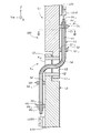
リンクL1は板状に下方に突出し左側に切欠かれたL1リンク結合部L1−1を備える。リンクL2は板状に上方に突出し右側が切欠かれL1リンク結合部L1−1と嵌合するL2リンク結合部L2−1を備える。L1リンク結合部L1−1及びL2リンク結合部L2−1は連結部KR1においてそれぞれ左右(Y軸方向)に貫く孔を備えており、L1リンク結合部L1−1とL2リンク結合部L2−1とが嵌合する時に一体となってL1リンク結合部L1−1とL2リンク結合部L2−1とを左右に貫く貫通孔を形成する。円筒状の部材である連結支持管12の右側をL1リンク結合部L1−1の貫通孔に嵌めこみ固定し、連結支持管12の左側をL2リンク結合部L2−1に嵌合させることによって、リンクL2はリンクL1に対して左右(Y軸方向)を軸線とする回動可能に連結され、リンクL1に設けられた貫通孔、リンクL2に設けられた貫通孔及び連結支持管12とによって、連結部KR1が構成される。リンクL1に固定されリンクL2に嵌合される連結支持管12は、管内部である連結支持管内孔13を備え、連結支持管内孔13はリンクL1及びリンクL2のそれぞれに設けられた貫通孔を通ってリンクL1及びリンクL2を貫通している。連結部KR1の回動軸は連結支持管内孔13と同軸であり、連結部KR1の回動軸が連結支持管内孔13を通るように構成されている。右方(Y軸負の方向)に設けられた連結支持管12の開口端はリンクL1の右側面になめらかに接続し、左方に設けられた連結支持管12の開口端はリンクL1の左側面になめらかに接続している。
Link L1 comprises L1 link coupling portion L1 -1 which is notched to the left protruding downward in a plate shape. Link L2 comprises an L2 link coupling portion L2 -1 which protrudes upward right is fitted with notched L1 link coupling portion L1 -1 in a plate shape. L1 link coupling portion L1 -1 and L2 link connection portion L2 -1 is provided with a hole penetrating the left and right at the connection portion K R1 (Y axis direction), L1 link coupling portion L1 -1 and L2 link coupling portion L2 - 1 and is forming a through hole penetrating in the lateral and L1 link coupling portion L1 -1 and L2 link coupling portion L2 -1 together when engaged. The right
光送受信モジュールLO2から延びた光ファイバケーブル11は、連結部KR1において左方(Y軸正の方向)へ屈曲し、連結支持管12の右側の開口端から連結支持管12の管内へ延びている。光ファイバケーブル11の屈曲部14において、被覆材C1及び光ファイバ芯線F1は下方(Z軸負の方向)から左方へ屈曲している。連結部KR1の近傍で屈曲する光ファイバケーブル11の屈曲部14では、被覆材C1及び光ファイバ芯線F1が屈曲する。被覆材C1のリンクL2に向く側縁部に比べ、光ファイバ芯線F1は大きな半径を有して屈曲する。光ファイバケーブル11に光ファイバ芯線F1を覆うように被覆材C1が設けられ、被覆材C1と光ファイバ芯線F1との間に設けられた空間において光ファイバ芯線F1が移動するため、光ファイバケーブル11の屈曲部14において光ファイバ芯線F1に大きな曲げ半径を確保し光ファイバ芯線F1が受ける荷重を緩和することが可能となる。また、リンクL2から連結支持管12へ延び光ファイバケーブル11が屈曲する時に、連結支持管12の開口部に光ファイバケーブル11の側縁部が当接する。光ファイバケーブル11が屈曲する時に、光ファイバ芯線F1が直接、連結支持管12の開口部に当接せず、被覆材C1が介在することによって光ファイバ芯線F1の破損が防止される。光ファイバ芯線F1は高屈曲性を有するとよく、光ファイバ芯線F1の許容曲げ半径は被覆材C1の許容曲げ半径よりも小さくなるように構成されている。光ファイバケーブル11の屈曲部14の曲げ半径が被覆材C1の許容曲げ半径よりも小さく光ファイバ芯線F1の許容曲げ半径よりも大きい時に、光ファイバ芯線F1は破損せず被覆材C1のみが破損しうるため、光ファイバ芯線F1を破損させることなく被覆材C1の破損によって光ファイバケーブル11の屈曲部14において曲げ半径の小さい箇所を同定することが可能となる。また、光ファイバ芯線F1の許容曲げ半径は被覆材C1の許容曲げ半径よりも小さいため、被覆材C1が光ファイバ芯線F1よりも破損しやすく、膝関節部KRの屈曲によって光ファイバ芯線F1に荷重がかかりやすい箇所を、被覆材C1の破損の度合いによって同定することが可能となる。
連結部KR1では、光ファイバケーブル11は連結支持管12の管内を通って敷設されている。連結支持管12の内径は、光ファイバケーブル11の外径よりも大きく、光ファイバケーブル11が連結支持管12において上下及び前後に移動することによって、屈曲部14において光ファイバケーブル11に加わるねじれや引っ張りなどの荷重の集中が緩和される。リンクL1及びL2に設けられた貫通孔に連結支持管12が設けられ、連結支持管12はリンクL1及びL2を互いに回動可能に連結している。連結支持管12にリンクL2のリンクL1に対する回動軸が通っているため、光ファイバケーブル11を膝関節部KRの屈曲によって変位しない回動軸に沿って敷設することが可能となる。光ファイバケーブル11を回動軸に沿って敷設することによって、膝関節部KRの屈曲時に加わる光ファイバケーブル11を変位させようとする荷重が抑えられる。
In the connection part KR1 , the
連結支持管12に敷設された光ファイバケーブル11は、連結支持管12を貫通し、リンクL2の左(Y軸正の方向)側面にまで延びている。連結支持管12の左端の開口部より突出した光ファイバケーブル11は、連結支持管12の左端の開口部において、下方(Z軸負の方向)へ屈曲し、リンクL2の左側面に沿って下方へ延びている。リンクL2に沿って、下方へ延びる光ファイバケーブル11は、リンクL2に設けられた芯線係止部Q2を通過する。リンクL2に設けられた芯線係止部Q2を光ファイバケーブル11が通過する時に、光ファイバケーブル11の被覆材C1が第2被覆材固定部Q2−2によってリンクL2に固定される。光ファイバケーブル11に設けられた光ファイバ芯線F1の移動は被覆材C1によって被覆材C1の管内に規制され、リンクL2に設けられた芯線係止部Q2において被覆材C1がリンクL2に固定されるため、光ファイバ芯線F1はリンクL2に設けられた芯線係止部Q2において、リンクL2に対して、リンクL2に固定された被覆材C1の管内で移動可能であるように係止される。
The
リンクL2に設けられた芯線係止部Q2を通過した光ファイバケーブル11は、リンクL2に沿って下方へ延び、リンクL1に設けられた光送受信モジュールLO3の近傍で、光送受信モジュールLO3よりも連結部KR1に近い場所に設けられた芯線保持部P2を通過する。芯線保持部P2に備えられた第1被覆材固定部P2−2によって被覆材C1はリンクL2に固定され、芯線保持部P2に備えられた芯線固定部P2−1によって光ファイバ芯線F1は被覆材C1に固定される。芯線保持部P2に備えられた第1被覆材固定部P2−2及び芯線固定部P2−1によって光ファイバ芯線F1はリンクL2に対して固定され保持される。
The
芯線係止部Q2を通過した光ファイバケーブル11の被覆材C1は、芯線保持部P2及び光送受信モジュールLO3との間で終端している。被覆材C1の終端部において、芯線固定部P2−1が被覆材C1から下方に設けられた光送受信モジュールLO3に向かって突出し、芯線固定部P2−1の中央から光ファイバ芯線F1が延び、光送受信モジュールLO3の光受信装置LO3Rに接続されている。
The covering material C1 of the
以上のように構成した光ファイバケーブル11を備える関節機構101の動作について説明する。膝関節部KRにおいて、リンクL1とリンクL2とは連結部KR1を介して回動可能に連結されている。光送受信モジュールLO2がリンクL1に設けられ、光送受信モジュールLO3がリンクL2に設けられ、光送受信モジュールLO2と光送受信モジュールLO3とが光ファイバケーブル11によって接続されている。光ファイバ芯線F1は芯線保持部P1及びP2によって対応するリンクL1及びリンクL2に保持され、芯線係止部Q1及びQ2によって、対応するリンクL1及びリンクL2に係止されている。光ファイバ芯線F1は芯線保持部P1と芯線保持部P2との間では、被覆材C1の管内を移動することが可能である。光ファイバ芯線F1が芯線保持部P1と芯線保持部P2との間では被覆材C1の管内を移動するため、膝関節部KRの屈曲によって加わる光ファイバ芯線F1への荷重が膝関節部KRに設けられた光ファイバ芯線F1に集中することなく、芯線保持部P1と芯線保持部P2との間の光ファイバ芯線F1に分散される。光送受信モジュールLO2の光送信装置LO2Tから送信された光信号は膝関節部KRを介して敷設された光ファイバケーブル11を通って光送受信モジュールLO3の光受信装置LO3Tに受信可能に伝送される。
The operation of the
以上のように構成した光ファイバケーブル11を備える関節機構101の効果について説明する。光ファイバケーブル11を備える関節機構101は、膝関節部KRを介して互いに回動可能に連結されたリンクL1及びリンクL2と、リンクL1及びリンクL2にそれぞれ設けられた光送受信モジュールLO2及びLO3と、光送受信モジュールLO2と光送受信モジュールLO3とを繋ぐように敷設されたケーブル芯線となる光ファイバ芯線F1を含む光ファイバケーブル11と、リンクL1の膝関節部KRから離れた位置に設けられ光ファイバ芯線F1をリンクL1に固定し保持する芯線保持部P1及びリンクL2の膝関節部KRから離れた位置に設けられ光ファイバ芯線F1をリンクL2に固定し保持する芯線保持部P2と、リンクL1の芯線保持部P1よりも連結部KR1に近い位置でリンクL1に設けられリンクL1に光ファイバ芯線F1を係止する芯線係止部Q1と、リンクL2の芯線保持部P2よりも連結部KR1に近い位置でリンクL2に設けられリンクL2に光ファイバ芯線F1を係止する芯線係止部Q2とを有する。光ファイバケーブル11がリンクL1及びL2に保持されつつ、光ファイバケーブル11が膝関節部KRでの屈曲に応じて移動可能であるように係止されるため、膝関節部KRでの屈曲によって光ファイバ芯線F1が受ける荷重を緩和することが可能となる。芯線保持部P1と芯線保持部P2の間の光ファイバ芯線F1に膝関節部KRでの屈曲に必要となる余長を持たせるように敷設することも可能である。
The effect of the
関節機構101は、光ファイバ芯線F1と光ファイバ芯線F1を光ファイバ芯線F1の軸線に直交する方向へ所定の範囲のみ移動可能に被覆する被覆材C1とを備える光ファイバケーブル11と、光信号を送受信する光送受信装置である光送受信モジュールLO1及びLO2とを備える。芯線係止部Q1及びQ2が被覆材C1を対応するリンクL1及びL2に固定する第2被覆材固定部Q1−2及びQ2−2を備え、被覆材C1及び第2被覆材固定部Q1−2及びQ2−2によって、光ファイバ芯線F1がリンクL1及びL2に所定の範囲に移動可能に係止される。光ファイバ芯線F1をリンクL1及びL2に所定の範囲で移動可能に係止する構成が被覆材C1及び第2被覆材固定部Q1−2及びQ2−2による簡単な構成で実現される。
The
芯線保持部P1及びP2は被覆材C1に固定する芯線固定部P1−1及びP2−1と被覆材C1をリンクL1及びL2に固定する第1被覆材固定部P1−2及びP2−2とを備え、光ファイバ芯線F1が芯線保持部P1及びP2に備えられた芯線固定部P1−1及びP2−1と芯線固定部P1−1及びP2−1とによってリンクL1及びL2に固定され保持される。 A first cover member fixing portion P1 -2 and P2 -2 core wire holding portion P1 and P2 for fixing the core wire fixing portion P1 -1 and P2 -1 and dressing C1 for fixing the covering material C1 to the link L1 and L2 comprising, an optical fiber core line F1 is held fixed by the core wire fixing portion P1 -1 and P2 -1 and the core wire fixing portion P1 -1 and P2 -1 provided in the core holding portions P1 and P2 to the link L1 and L2 .
膝関節部KRがリンクL2に対して1軸の回動軸を中心とする回動可能にリンクL2をリンクL1に連結する1つの連結部KR1によって構成され、連結部KR1の回動軸に沿った連結支持管内孔13を有する連結支持管12を備え、光ファイバケーブル11は連結支持管内孔13を通るように敷設されている。光ファイバ芯線F1が回動軸に沿った連結支持管内孔13に敷設されるため、膝関節部KRの屈曲時に加わる光ファイバ芯線F1への荷重が抑えられる。光ファイバ芯線F1は芯線保持部P1及びP2において対応するリンクL1及びL2に固定され、芯線保持部P1とP2の間の光ファイバ芯線F1は被覆材C1の管内において移動可能であり、膝関節部KRの屈曲時の光ファイバケーブル11の曲げ、引っ張り、ねじれ等の荷重が連結部KR1の光ファイバ芯線F1に集中せず、光ファイバ芯線F1の損傷が防止される。
Is constituted by the knee joint K R is pivotally link L2 to be connected to the
<<第2実施形態>>
図5に示されるように、腕部ARに備えられたリンクA1は上下(Z軸方向)に延び、リンクA1の右側面(Y軸負の方向に向く面)には光送受信モジュールAO1が設けられている。リンクA1の下方には、上下に延びるリンクEが設けられており、リンクA1の下端及びリンクEの上端は連結部ER2を介してリンクEがリンクAに対して左右を軸とする回動可能であるように連結されている。連結部ER2においてリンクA1及びリンクEは連結時にリンクA1及びリンクEを共に回動軸に沿って左右に貫通する貫通孔をそれぞれ備え、連結支持管22がそれらの貫通孔を共に通過するように嵌合されている。連結支持管22の右端がリンクA1の貫通孔に固定され、連結支持管22の左端がリンクEの貫通孔に嵌合することによって連結され、リンクEは連結支持管22を備える連結部ER1を介してリンクEに左右(Y軸方向)を軸線とする回動可能に連結されている。リンクA2は連結部ER2においてリンクEに対して前後(X軸方向)を軸線とする回動可能に支持されている。連結部ER2にはリンクE及びリンクA2を前後に貫通する孔が設けられており、その貫通する孔に、前後に延びた管である連結支持管23が通されている。リンクEの前後に貫通する孔に連結支持管23の後端が固定され、リンクAの前後に貫通する孔に連結支持管23の前端が嵌合することによって、リンクA2はリンクEに対して前後を軸線とする回動可能に連結される。リンクA2は上下に延びた部材であって、連結部ER2の下方に光送受信モジュールAO2を備える。光送受信モジュールAO1とAO2とは光ファイバケーブル21によって接続され、光ファイバケーブル21がリンクA1及びリンクA2に敷設され、光ファイバケーブル21を備える関節機構201が腕部ARに構成されている。第1実施形態と同様に、光ファイバケーブル21は光ファイバ芯線F2及び光ファイバ芯線F2を管内に備えチューブ状に形成された被覆材C2とを備える。
<< Second Embodiment >>
As shown in FIG. 5, the link provided in the arm portion A R A1 extends vertically (Z-axis direction), the optical transceiver module AO1 on the right side of the link A1 (the surface facing in the direction of Y-axis negative) Is provided. Below the link A1, is provided with a link E extending vertically, the upper end of the lower end of the link A1 and link E rotation to the shaft of the left and right relative to the link E links A through the connecting portion E R2 Connected as possible. In the connection part ER2 , the link A1 and the link E are respectively provided with through-holes penetrating the link A1 and the link E left and right along the rotation axis so that the
光ファイバケーブル21の一端は光送受信モジュールAO1の光送信装置AO1Tに接続され、光送受信モジュールAO1近傍で連結部ER1に向く側に設けられた芯線保持部P3を通過する。第1実施形態と同様に、芯線保持部P3は芯線固定部及び第1被覆材固定部を備える。光ファイバケーブル21は被覆材C2及び光ファイバ芯線F2を備え、光ファイバ芯線F2が芯線固定部によってリンクA2に固定され、被覆材C2が第1被覆材固定部によってリンクA1に固定される。芯線保持部P3に備えられた芯線固定部及び第1被覆材固定部によって光ファイバ芯線F2はリンクA1に固定され保持される。
One end of the
芯線保持部P3を通過した光ファイバケーブル21は、芯線保持部P3より連結部ER1の近傍でリンクA1に設けられた芯線係止部Q3にまで延びている。芯線係止部Q3には第2被覆材固定部が備えられており、第2被覆材固定部によって光ファイバケーブル21の被覆材C2がリンクEに固定される。芯線係止部Q3において、光ファイバ芯線F2が芯線係止部Q3に備えられた第2被覆材固定部によって被覆材C2の管内に移動可能に係止される。光ファイバケーブル21は、芯線係止部Q3を通過し、連結部ER1にまで延びている。
光ファイバケーブル21は、連結部ER1で屈曲し、リンクA1の右(Y軸負の方向)側面から、左方に向けて連結部ER1に設けられた連結支持管22の連結支持管内孔24を通過し、リンクEの左側面にまで到達する。光ファイバケーブル21は連結部ER1の回動軸に沿って設けられた連結支持管22の連結支持管内孔24を通って敷設される。連結部ER1の近傍の屈曲部において光ファイバケーブル21は屈設され、連結部ER1の近傍の屈曲部において光ファイバ芯線F2及び被覆材C2も屈曲する。光ファイバ芯線F2の許容曲げ半径は被覆材C2の許容曲げ半径よりも小さく、光ファイバ芯線F2は破損せず被覆材C2のみが破損しうるため、被覆材C2の破損によって光ファイバケーブル21の屈曲部において曲げ半径の小さい箇所を同定することが可能となる。
光ファイバケーブル21は、連結部ER1よりリンクEの左(Y軸正の方向)側面まで延び、下方(Z軸負の方向)に向かって屈曲し、リンクEの左側面に沿って下方へ延びている。芯線係止部Q4がリンクEの左側面の連結部ER1の近傍に備えられている。芯線係止部Q4は第1実施形態と同様に第2被覆材固定部を備え、第2被覆材固定部によって被覆材C2がリンクEの左側面に固定される。芯線係止部Q4において光ファイバ芯線F2はリンクEに固定された被覆材C2の管内を移動可能にリンクEの左側面に係止される。
リンクEの背面(X軸負の方向に向く側面)のリンクEの左側面に備えられた芯線係止部Q4より下方の連結部ER2の近傍には芯線係止部Q5が設けられている。芯線係止部Q4を通過した光ファイバケーブル21は、リンクEの左側面から下方へ進みつつリンクEの背面側へ屈曲しリンクEの背面に沿って下方に向かって延びている。リンクEの背面に沿って下方に延びる光ファイバケーブル21は芯線係止部Q5を通過する。光ファイバ芯線F2は芯線係止部Q5においてリンクEの背面に係止される。光ファイバケーブル21は芯線係止部Q5を通過しリンクEの背面に沿って下方へ延び連結部ER2に達している。
Core locking portion Q5 is provided in the vicinity of the link E of the back connecting portion below the core locking portion Q4 provided on the left side of the link E of (X side facing in the direction of the axis negative) E R2 . The
光ファイバケーブル21は、連結部ER2において屈曲し、連結部ER2に設けられた連結支持管23の連結支持管内孔25を背面から前面に向かって進んで通過し、リンクA2の前面にまで到達する。光ファイバケーブル21は連結部ER2において下方へ屈曲して延び、リンクA2の前面で連結部ER2の近傍に備えられた芯線係止部Q6を通過する。芯線係止部Q6において、光ファイバ芯線F2はリンクA2の前面に係止されている。光ファイバケーブル21は、芯線係止部Q6を通過し、芯線係止部Q6の下方で光送受信モジュールAO2の近傍に設けられた芯線保持部P4に到達する。芯線保持部P4は芯線固定部及び第1被覆材固定部を備え、光ファイバ芯線F2が芯線保持部P4の芯線固定部によって被覆材C2に固定され、被覆材C2が芯線保持部P4の被覆材固定部によって固定される。光ファイバ芯線F2は芯線保持部P4が備える芯線固定部及び第1被覆材固定部によってリンクA2に固定され保持される。光ファイバケーブル21は芯線保持部P4の下側において被覆材C2が終端し被覆材C2から芯線固定部が突出している。光ファイバ芯線F2は芯線固定部の中央に保持され、下方に延び芯線保持部P4の下方に設けられた光送受信モジュールAO2の光受信装置AO2Rに接続している。
図5に示されるようにリンクA1が芯線保持部P3及び芯線係止部Q3との間に更に芯線係止部Q11を備えてもよい。リンクEが芯線係止部Q4とQ5の間に芯線係止部Q12及びQ13を備えてもよい。リンクA2が芯線係止部Q6と芯線保持部P4との間に更に芯線係止部Q14を備えてもよい。芯線係止部Q11、Q12、Q13及びQ14を備えることによって、光ファイバケーブルがリンクA1、E及びA2に沿うように敷設することが可能となる。 As shown in FIG. 5, the link A1 may further include a core wire locking portion Q11 between the core wire holding portion P3 and the core wire locking portion Q3. The link E may include core wire locking portions Q12 and Q13 between the core wire locking portions Q4 and Q5. The link A2 may further include a core wire locking portion Q14 between the core wire locking portion Q6 and the core wire holding portion P4. By providing the core wire locking portions Q11, Q12, Q13 and Q14, the optical fiber cable can be laid along the links A1, E and A2.
以上のように構成した光ファイバケーブル21を備える関節機構201の動作について説明する。光ファイバケーブル21は芯線保持部P3及びP4と芯線係止部Q3及びQ6によって、対応するリンクA1及びリンクA2に保持及び係止される。リンクEには芯線係止部Q4及びQ5が設けられ、光ファイバ芯線F2はリンクEに係止される。光送受信モジュールAO1の光送信装置AO1Tから送信された光信号は、光ファイバ芯線F2に沿って伝送し、光送受信モジュールAO2の光受信装置AO2Rに到達する。光ファイバケーブル21は連結部ER1及び連結部ER2の回動軸に沿った連結支持管22及び23の連結支持管内孔24及び25に敷設されるため、光ファイバケーブル21が回動軸の近傍で保持され、肘関節部ERの屈曲時に加わる光ファイバ芯線F2への荷重を抑えることが可能となる。
Operation | movement of the
以上のように構成した光ファイバケーブル21を備える関節機構201の効果について説明する。関節機構201は連結部ER1及びER2とリンクEを介して互いに変位可能に連結されたリンクA1及びリンクA2と、リンクA1及びリンクA2に設けられた光送受信モジュールAO1及びAO2と、リンクA1の光送受信モジュールAO1とリンクA2の光送受信モジュールAO2とを繋ぐように敷設された光ファイバ芯線F2を含む光ファイバケーブル21と、光信号を送受信する光送受信装置である光送受信モジュールAO1及びAO2と、リンクA1及びリンクA2のそれぞれに関節から離れた位置に設けられ、光ファイバ芯線F2と対応するリンクに保持する芯線保持部P3及びP4とを備える。関節機構201はリンクA1に設けられた芯線保持部P3よりも肘関節部ERに近い位置に設けられ、光ファイバ芯線F2を被覆材C2の管内で移動可能に係止する芯線係止部Q3を備える。関節機構201は、リンクA2に設けられた芯線保持部P4よりも肘関節部ERに近い位置に設けられ、光ファイバ芯線F2を被覆材C2の管内で移動可能に係止する芯線係止部Q6を備える。光ファイバケーブル21がリンクA1及びA2に保持されつつ、光ファイバケーブル21が肘関節部ERでの屈曲に応じて移動可能であるように係止されるため、肘関節部ERでの屈曲によって光ファイバケーブル21が受ける荷重を緩和することが可能となる。
The effect of the
関節機構201は、リンクA1とリンクA2との間に連結される中間リンクとなるリンクEを備える。リンクA1を互いに1つの回動軸を中心とする回動可能に連結する連結部ER1を介してリンクEに連結され、リンクEは互いに1つの回動軸を中心とする回動可能に連結する連結部ER2を介してリンクA2に連結されている。光ファイバケーブル21はリンクEに設けられた2つの芯線係止部Q4及びQ5によってリンクEに係止されている。2つの芯線係止部Q4及びQ5によって、光ファイバ芯線F2をリンクA1及びリンクA2の間に連結されたリンクEに係止することが可能となる。
The
連結部ER1はその回動軸に沿って設けられた連結支持管内孔24を備える連結支持管22を有し、連結部ER2はその回動軸にそって連結支持管内孔25を備える連結支持管23を有する。光ファイバケーブル21は連結支持管内孔24及び25を通るように敷設されている。光ファイバケーブル21は回動軸に沿って設けられるため、肘関節部ERの屈曲時の光ファイバケーブル21の曲げ、引っ張り、ねじれ等の荷重が連結部KR1の光ファイバ芯線F2に集中せず、光ファイバ芯線F2の損傷が防止される。
The connecting part E R1 has a connecting
<<第3実施形態>>
図6(A)に示されるように、リンクM1は上から下に管状に延び、その下端に設けられた開口部において径内方向に突出した第1係止爪M1−1を有する。リンクM1の管内でその内壁には、光送受信モジュールMO1が固定されている。リンクM1の下側からリンクM1の内孔に嵌合し円筒形に形成されたリンクM2が備えられている。リンクM2の管内でその内壁には、光送受信モジュールMO2が固定されている。リンクM1の内孔とリンクM2の内孔は連通しており、リンクM2の上側の開口端は、リンクM1の管内に収められている。リンクM2の開口端の外周には、リンクM1の内周に当接するまで径外方向へ突出した第2係止爪M2−1が備えられている。リンクM1の第1係止爪M1−1は、リンクM2の外周に当接している。リンクM1がリンクM2に対して下方向へ移動した時に第1係止爪M1−1と第2係止爪M2−1とが係合し、リンクM1がリンクM2から上方向へ離脱することを防止している。リンクM2の外周で、第2係止爪M2−1の下方には、径外方向へ突出した第2係止突起M2−2が備えられている。図6の(B)に示されるように、リンクM1がリンクM2に対して下方向へ移動した時に第1係止爪M1−1と第2係止突起M2−2が係合し、リンクM1の下方向への移動を規制している。リンクM2はリンクM1に対して上下にスライドし、リンクM2はリンクM1に対して上下に並進移動することが可能であるように連結されている。リンクM2はリンクM1に対して上下に並進移動することによって、互いに連結されたリンクM1及びリンクM2の全長が伸縮する伸縮関節部MRを備える関節機構301が形成されている。
<< Third Embodiment >>
As shown in FIG. 6 (A), link M1 extends tubular from top to bottom, has a first locking claw M1 -1 projecting radially inward direction through an opening provided at its lower end. An optical transmission / reception module MO1 is fixed to the inner wall of the link M1. A link M2 that is fitted into the inner hole of the link M1 from the lower side of the link M1 and formed in a cylindrical shape is provided. An optical transmission / reception module MO2 is fixed to the inner wall of the link M2. The inner hole of the link M1 and the inner hole of the link M2 communicate with each other, and the upper open end of the link M2 is housed in the pipe of the link M1. The outer periphery of the open end of the link M2, the second locking claw M2 -1 projecting radially outward direction until it abuts against the inner circumference of the link M1 are provided. The first locking claw M1 -1 links M1 is in contact with the outer periphery of the link M2. That link M1 is a first locking claw M1 -1 and a second locking claw M2 -1 engages when moving downward to the link M2, link M1 is disengaged from link M2 upward It is preventing. In the outer periphery of the link M2, below the second locking claw M2 -1, the second locking protrusion M2 -2 projecting radially outward direction are provided. As shown in (B) of FIG. 6, the link M1 is first locking claw M1 -1 and the second locking protrusion M2 -2 engages when moving downward to the link M2, link M1 Is restricted from moving downward. The link M2 slides up and down with respect to the link M1, and the link M2 is connected so as to be able to translate up and down with respect to the link M1. Link M2 is by translation up and down with respect to the link M1, it is formed
伸縮関節部MRに第1実施形態及び第2実施形態と同様に光ファイバ芯線F3及び被覆材C3を備える光ファイバケーブル31が備えられている。光ファイバケーブル31は光送受信モジュールMO1の光送信装置MO1Tに一端側が接続され、連通したリンクM1及びM2の管内を通り、他端側が光送受信モジュールMO2の光受信装置MO2Rに接続されている。光送受信モジュールMO1の近傍のリンクM1の内壁に設けられた芯線保持部P5において光ファイバ芯線F3がリンクM1に固定され保持されている。リンクM1の内壁であって芯線保持部P5よりも伸縮関節部MRに近い側には、芯線係止部Q7が設けられており、芯線係止部Q7において光ファイバ芯線F3はリンクM1に固定された被覆材C3の管内で移動可能にリンクM1に係止されている。
光ファイバケーブル31の被覆材C3及び光ファイバ芯線F3は光送受信モジュールMO2の近傍のリンクM2の内壁に設けられた芯線保持部P6において、リンクM2に固定されており、光ファイバ芯線F3はリンクM2に保持されている。リンクM2の内壁であって芯線保持部P6よりも伸縮関節部MRに近い側には、芯線係止部Q8が設けられており、芯線係止部Q8において光ファイバ芯線F3はリンクM2に係止されている。リンクM2に固定されている芯線保持部P6及び芯線係止部Q8は、リンクM2の第2係止突起M2−2よりも下方に位置している。
The covering material C3 and the optical fiber core wire F3 of the
以上のように構成した光ファイバケーブル31を備える関節機構301の動作について説明する。光送受信モジュールMO1から送信された光信号は、光ファイバケーブル31に設けられた光ファイバ芯線F3に沿って伝送され、光送受信モジュールMO2で受信される。図5(A)に示されるように、リンクM1の第1係止爪M1−1がリンクM2の第2係止爪M2−1と係合する時、リンクM1がリンクM2に対して最も突出した突出位置にある。突出位置において光ファイバケーブル31は連通したリンクM1及びM2の管内を通り、光ファイバケーブル31は一端が光送受信モジュールMO1に接続され、他端が光送受信モジュールMO2に接続されている。光送受信モジュールMO1から送信された光信号は、光ファイバケーブル31を伝送し、光送受信モジュールMO2に受信される。リンクM1が突出位置から下にスライドし、リンクM1はリンクM2に対して下方に後退し並進変位することが可能である。図5(B)に示されるように、リンクM1の第1係止爪M1−1がリンクM2の第2係止突起M2−2と係合する時、リンクM1がリンクM2に対して最も後退した後退位置にある。突出位置と後退位置との間を変位することによって、リンクM2及びリンクM1によって形成される部材の上下方向の長さは伸縮し、伸縮関節部MRにおいて、リンクM1及びM2は伸縮可能であるように連結されている。後退位置においても、光ファイバケーブル31は連通したリンクM1及びM2の管内を通り、光ファイバ芯線F3は一端が光送受信モジュールMO1に接続され、他端が光送受信モジュールMO2に接続されている。光送受信モジュールMO1から送信された光信号は、光ファイバケーブル31を伝送し、光送受信モジュールMO2に受信される。
The operation of the
突出位置に比べ後退位置では、光送受信モジュールMO1と光送受信モジュールMO2との距離は短くなるため、リンクM1に設けられた芯線係止部Q7とリンクM2に設けられた芯線係止部Q8との間に係止された光ファイバケーブル31は、リンクM1及びM2の管内で屈曲して保持される。後退位置での光ファイバケーブル31の屈曲部の曲げ半径が許容曲げ半径に比べ大きくなるように、光ファイバケーブル31及び芯線係止部Q7及びQ8は構成されており、光送受信モジュールMO1から送信された光信号は光送受信モジュールMO2で受信することが可能になっている。リンクM1に設けられた芯線保持部P5及び芯線係止部Q7は、後退位置でもリンクM2の第2係止爪M2−1と当接しない程度に伸縮関節部MRから離れて固定されている。
Since the distance between the optical transmission / reception module MO1 and the optical transmission / reception module MO2 is shorter in the retracted position than the protruding position, the core wire locking portion Q7 provided in the link M1 and the core wire locking portion Q8 provided in the link M2 The
以上のように構成した光ファイバケーブル31を備える関節機構301の効果について説明する。関節機構301は、伸縮関節部MRを介して互いに並進変位可能に連結されたリンクM1及びM2と、リンクM1及びリンクM2に設けられ光信号を送受信する光送受信装置である光送受信モジュールMO1及びMO2と、光送受信モジュールMO1と光送受信モジュールMO2とを繋ぐように敷設された光ファイバケーブル31を備える。光ファイバケーブル31は光ファイバ芯線F3を含み、関節機構301はリンクM1に伸縮関節部MRから離れた位置に設けられ光ファイバ芯線F3をリンクM1に保持する芯線保持部P5及びP6を備える。関節機構301は、リンクM1の芯線保持部P5よりも伸縮関節部MRに近い位置に設けられ被覆材C3の管内で移動可能に光ファイバ芯線F3を係止する芯線係止部Q7と、リンクM2の芯線保持部P6よりも伸縮関節部MRに近い位置に設けられ被覆材C3の管内で移動可能に光ファイバ芯線F3を係止する芯線係止部Q8とを備える。光ファイバケーブル31がリンクM1及びM2に保持されつつ、光ファイバケーブル31が伸縮関節部MRでの伸縮に応じて移動可能であるように係止されるため、伸縮関節部MRでの伸縮によって光ファイバ芯線F3が受ける荷重を緩和することが可能となる。
The effect of the
伸縮関節部MRにおいて、リンクM2に対してリンクM1が上下に並進して変位するように連結され、伸縮関節部MRを介してリンクM1及びM2は伸縮可能に連結されている。リンクM1に設けられた光送受信モジュールMO1とリンクM2に設けられた光送受信モジュールMO2とを接続する光ファイバケーブル31を有し、リンクM2に対してリンクM1が上下に並進して変位する伸縮可能な伸縮関節部MRが構成され、伸縮関節部MRにおいて光ファイバケーブル31を備える関節機構301を構成することが可能となる。
In telescopic joints M R, it is connected to link M1 to the link M2 is displaced in translation in the vertical direction, the link M1 and M2 via an elastic articulation M R are telescopically connected. The
光ファイバケーブル31の被覆材C3及び光ファイバ芯線F3は光送受信モジュールMO2の近傍のリンクM2の内壁に設けられた芯線保持部P6において、リンクM2に固定されており、光ファイバ芯線F3はリンクM2に保持されている。リンクM2の内壁であって芯線保持部P6よりも伸縮関節部MRに近い側には、芯線係止部Q8が設けられており、芯線係止部Q8において光ファイバ芯線F3はリンクM2に係止されている。リンクM2に固定されている芯線保持部P6及び芯線係止部Q8は、リンクM2の第2係止突起M2−2よりも下方に位置している。
The covering material C3 and the optical fiber core wire F3 of the
<<第4実施形態>>
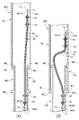
図7に示されるように、リンクU1は上下に延びた下方に向けて開口する管状に形成され、リンクU1の下部の管内壁には径外方向に凹み周方向へ連なった凹部U1−1が設けられている。リンクU1には、リンクU1の下端の開口部からリンクU1と同軸になるように挿入された管状のリンクU2が連結されており、リンクU1とリンクU2とは連通している。リンクU2の外周面には、凹部U1−1と係合し、リンクU2のリンクU1に対する上下方向の変位を規制する凸部U2−1が設けられている。凹部U1−1と凸部U2−1とが係合することによって、リンクU2はリンクU1に対してリンクU1の軸線方向を中心とするねじれ変位可能に支持されている。リンクU1とリンクU2とによって、ねじれ変位可能な捩回関節部URを備える関節機構401が形成されている。
<< Fourth Embodiment >>
As shown in FIG. 7, the link U1 is formed in a tubular which is open downwardly extending vertically, the concave portion U1 -1 in the lower portion of the inner wall of the link U1 which continuous to recessed circumferentially radially outward Is provided. The link U1 is connected to a tubular link U2 inserted so as to be coaxial with the link U1 from the opening at the lower end of the link U1, and the link U1 and the link U2 communicate with each other. The outer peripheral surface of the link U2, engages the recess U1 -1, protrusions U2 -1 is provided for restricting the vertical displacement for the link U1 link U2. By and the recess U1 -1 and the convex portion U2 -1 engaged, links U2 is twisted displaceably supported around the axis line direction of the link U1 for the link U1. The link U1 and the link U2,
関節機構401には第1実施形態〜第3実施形態と同様に光ファイバ芯線F4及び被覆材C4を備える光ファイバケーブル41が備えられている。捩回関節部URより上側であってリンクU1の管内には、光送受信モジュールUO1が固定されている。光ファイバケーブル41の光ファイバ芯線F4はその一端側が光送受信モジュールUO1の光送信装置に接続され、連通したリンクU1及びリンクU2の管内を通り、他端側がリンクU2の管内に固定された光送受信モジュールUO2に接続されている。光送受信モジュールUO1の近傍のリンクU1の管内の内壁に設けられた芯線保持部P7において光ファイバ芯線F4及び被覆材C4がリンクU1に固定され保持されている。芯線保持部P7よりも捩回関節部URに近く、リンクU1の内孔に設けられリンクU1の軸線に沿う位置まで径内方向に突出した突起上に芯線係止部Q9が設けられている。芯線係止部Q9はリンクU1の軸線に沿って設けられている。芯線保持部P7を通過した光ファイバケーブル41は軸線方向かつ下方へ延びて芯線係止部Q9を通過し、その光ファイバ芯線F4はリンクU1に固定された被覆材C4の管内で移動可能にリンクU1に係止されている。
The
リンクU2の管内で捩回関節部URより下側には、リンクU2の軸線に沿う位置まで径内方向に突出する突起が備えられている。光ファイバケーブル41は下方へ延び、その突起上に設けられた芯線係止部Q10を通過する。芯線係止部Q10において、光ファイバケーブル41は、その光ファイバ芯線F4がリンクU1に固定された被覆材C4の管内で移動可能にリンクU1に係止されている。芯線係止部Q9を通過した光ファイバケーブル41は、下方かつリンクU2の内壁まで延び、リンクU2の管内の内壁に設けられた芯線保持部P8を通過する。芯線保持部P8において光ファイバケーブル41の光ファイバ芯線F4及び被覆材C4がリンクU2に固定され保持されている。芯線保持部P8の下側であってリンクU2の管内の内壁には光送受信モジュールUO2が固定されている。芯線保持部P8と光送受信モジュールUO2との間で被覆材C4は終端し、光ファイバ芯線F4が芯線保持部P8から延びて光送受信モジュールUO2の光受信モジュールに接続されている。
The lower side of the joint portion U R Kai twisting in the tube link U2, protrusions protruding in the radially inward direction to a position along the axis of the link U2 are provided. The
以上のように構成した光ファイバケーブル41を備える関節機構401の効果について説明する。関節機構401は、捩回関節部URを介して互いにねじれ変位可能に連結されたリンクU1及びU2と、リンクU1及びリンクU2に設けられ光信号を送受信する光送受信装置である光送受信モジュールUO1及びUO2と、光送受信モジュールUO1と光送受信モジュールUO2とを繋ぐように敷設された光ファイバケーブル41を備える。光ファイバケーブル41は光ファイバ芯線F4を含み、関節機構401はリンクU1に捩回関節部URから離れた位置に設けられ光ファイバ芯線F4をリンクU1及びU2に保持する芯線保持部P7及びP8をそれぞれ備える。関節機構401は、リンクU1の芯線保持部P7よりも捩回関節部URに近い位置に設けられ被覆材C4の管内で移動可能に光ファイバ芯線F4を係止する芯線係止部Q9と、リンクU2の芯線保持部P6よりも捩回関節部URに近い位置に設けられ被覆材C4の管内で移動可能に光ファイバ芯線F4を係止する芯線係止部Q10とを備える。光ファイバケーブル41の芯線係止部Q9と芯線係止部Q10との間に敷設される光ファイバ芯線F4は捩回関節部URでのねじれ変位の軸線に沿って設けられるため、捩回関節部URのねじれ変位によって加わる光ファイバ芯線F4への荷重が緩和される。光ファイバケーブル41の被覆材C4は捩回関節部URのねじれ変位によって破損しない程度の可撓性を有する。
The effect of the
以上で具体的実施形態の説明を終えるが、本発明は上記実施形態に限定されることなく幅広く変形実施することができる。本実施形態では、光ファイバケーブルを1本、異なるリンクに設けられた2つの光送受信モジュールの間を、連結部を介して接続する構成としたが、関節を通過する光ファイバケーブルを複数設けてもよい。 Although the description of the specific embodiment is finished as described above, the present invention is not limited to the above embodiment and can be widely modified. In this embodiment, one optical fiber cable and two optical transmission / reception modules provided on different links are connected via a connecting portion. However, a plurality of optical fiber cables that pass through joints are provided. Also good.
本実施形態では、リング状に構成された光ファイバケーブルネットワークに光ファイバケーブルが設けられるものとしたが、光ファイバケーブルネットワークのトポロジに限定されない。光ファイバケーブルが設けられる光ファイバケーブルネットワークは、スター型、ハブ型等のあらゆるトポロジを有するものであってよい。 In the present embodiment, the optical fiber cable is provided in the optical fiber cable network configured in a ring shape, but is not limited to the topology of the optical fiber cable network. The optical fiber cable network provided with the optical fiber cable may have any topology such as a star type or a hub type.
関節にケーブルが敷設されるとしたが、本明細書に記載の「敷設」とは、必ずしも「敷くように」ということを意味せず、関節に通信や光通信を可能とするようにケーブルが設けられる態様を意味する。 Although it is assumed that a cable is laid at a joint, the “laying” described in this specification does not necessarily mean “to lay”, and the cable is connected so that communication and optical communication can be performed at the joint. It means the aspect provided.
本実施形態では、光ファイバケーブルが関節を通過する構成としたが、光ファイバケーブルと光ファイバケーブルに沿って配線された電気信号線とが関節を通過する構成としてもよい。光ファイバ芯線は電気信号線に被覆材を介して接するため、光ファイバ芯線と電気信号線とが直接接触することによる光ファイバ芯線の摩耗が防止される。 In the present embodiment, the optical fiber cable passes through the joint. However, the optical fiber cable and the electrical signal line wired along the optical fiber cable may pass through the joint. Since the optical fiber core wire is in contact with the electric signal line through the covering material, wear of the optical fiber core wire due to direct contact between the optical fiber core wire and the electric signal line is prevented.
101 :第1の実施形態を示す関節機構
KR :膝関節部
KR1 :連結部
LO1、LO2 :光送受信モジュール
L1、L2 :リンク
11 :光ファイバケーブル
F1 :光ファイバ芯線
C1 :被覆材
P1、P2 :芯線保持部
Q1、Q2 :芯線係止部
P1−1 :芯線固定部
P1−2 :第1被覆材固定部
Q1−2 :第2被覆材固定部
12 :連結支持管
13 :連結支持管内孔
201 :第2の実施形態を示す関節機構
ER :肘関節部
ER1、ER2 :連結部
AO1、AO2 :光送受信モジュール
A1、A2 :リンク
E :リンク
21 :光ファイバケーブル
F2 :光ファイバ芯線
C2 :被覆材
P3、P4 :芯線保持部
Q3〜Q6 :芯線係止部
Q11〜Q14 :芯線係止部
22、23 :連結支持管
24、25 :連結支持管内孔
301 :第3の実施形態を示す関節機構
MR :伸縮関節部
MO1、MO2 :光送受信モジュール
M1、M2 :リンク
31 :光ファイバケーブル
F3 :光ファイバ芯線
C3 :被覆材
P5、P6 :芯線保持部
Q7、Q8 :芯線係止部
401 :第4の実施形態を示す関節機構
UR :伸縮関節部
UO1、UO2 :光送受信モジュール
U1、U2 :リンク
41 :光ファイバケーブル
F4 :光ファイバ芯線
C4 :被覆材
P7、P8 :芯線保持部
Q9、Q10 :芯線係止部
101: Joint mechanism K R showing the first embodiment K R : Knee joint K R1 : Connection portion LO1, LO2: Optical transmission / reception module L1, L2: Link 11: Optical fiber cable F1: Optical fiber core wire C1: Cover material P1, P2: core holding portion Q1, Q2: core securing portion P1 -1: core fixing portion P1 -2: first covering member fixing portion Q1 -2: second coating material fixing portion 12: connecting supporting tube 13: connecting supporting tube Hole 201: Joint mechanism E R showing second embodiment: Elbow joint portions E R1 , E R2 : Connection portions AO1, AO2: Optical transmission / reception modules A1, A2: Link E: Link 21: Optical fiber cable F2: Optical fiber Core wire C2: Coating materials P3, P4: Core wire holding portions Q3-Q6: Core wire locking portions Q11-Q14: Core wire locking portions 22, 23: Connection support tubes 24, 25: Connection support tube inner holes 301: Joint mechanism showing a third embodiment M R: stretch joints MO1, MO2: optical transceiver module M1, M2: link 31: optical fiber cable F3: optical fiber core line C3: dressing P5, P6: core holding portion Q7, Q8 : core securing portion 401: joint showing a fourth embodiment mechanism U R: stretch joints UO1, UO2: optical transceiver module U1, U2: link 41: optical fiber cable F4: optical fiber core line C4: dressing P7, P8: Core wire holding part Q9, Q10: Core wire locking part
Claims (11)
前記第1リンクの前記信号送受信装置と前記第2リンクの前記信号送受信装置とを繋ぐように敷設されるケーブル芯線を含むケーブルと、
前記第1リンク及び前記第2リンクのそれぞれに関節から離れた位置に設けられ、前記ケーブル芯線を対応するリンクに保持する芯線保持部と、
前記第1リンク及び前記第2リンクのそれぞれの前記芯線保持部よりも前記関節に近い位置に設けられ、前記ケーブル芯線を対応するリンクに所定の範囲で移動可能に係止する芯線係止部とを備えることを特徴とする関節機構。 A first link and a second link, which are connected to each other via a joint so as to be displaceable, each having a signal transmitting and receiving device;
A cable including a cable core laid so as to connect the signal transmission / reception device of the first link and the signal transmission / reception device of the second link;
A core wire holding portion that is provided at a position away from the joint in each of the first link and the second link, and holds the cable core wire in a corresponding link;
A core wire locking portion provided at a position closer to the joint than the core wire holding portions of each of the first link and the second link, and for locking the cable core wire to a corresponding link so as to be movable within a predetermined range; A joint mechanism comprising:
前記信号送受信装置が光送受信装置であって、
前記ケーブルが前記光ファイバ芯線と前記光ファイバ芯線の軸線に直交する方向へ所定の範囲で移動可能に被覆する被覆材とを有する光ファイバケーブルであり、
前記芯線係止部が前記被覆材を前記リンクに固定する被覆材固定部を含むことを特徴とする請求項1又は請求項2に記載の関節機構。 The cable core is an optical fiber core;
The signal transmission / reception device is an optical transmission / reception device,
The cable is an optical fiber cable having the optical fiber core wire and a covering material that is movably covered in a predetermined range in a direction orthogonal to the axis of the optical fiber core wire,
The joint mechanism according to claim 1 or 2, wherein the core wire locking portion includes a covering material fixing portion that fixes the covering material to the link.
前記連結部が前記回動軸に沿って設けられた内孔を備える回動軸部材を有し、
前記光ファイバケーブルが前記内孔を通るように敷設されることを特徴とする請求項4又は請求項5に記載の関節機構。 The joint is configured by a connecting portion that connects the second link to the first link so that the second link can rotate with respect to the first link about one rotation axis.
The connecting portion has a rotating shaft member having an inner hole provided along the rotating shaft;
The joint mechanism according to claim 4 or 5, wherein the optical fiber cable is laid so as to pass through the inner hole.
前記第1リンクはリンクを互いに1つの回動軸を中心とする回動可能に連結する連結部を介して順番に前記第2リンクに連結され、
前記中間リンクのそれぞれに前記芯線係止部が少なくとも2つ設けられることを特徴とする請求項4又は請求項5に記載の関節機構。 Comprising at least one intermediate link coupled between the first link and the second link;
The first link is connected to the second link in order via a connecting portion that connects the links to each other so as to be rotatable around one rotation axis.
The joint mechanism according to claim 4 or 5, wherein at least two core wire locking portions are provided in each of the intermediate links.
前記光ファイバケーブルが全ての前記内孔を通るように敷設されることを特徴とする請求項7に記載の関節機構。 All of the connecting portions have a rotation shaft member having an inner hole provided along the rotation shaft,
The joint mechanism according to claim 7, wherein the optical fiber cable is laid so as to pass through all the inner holes.
Priority Applications (4)
| Application Number | Priority Date | Filing Date | Title |
|---|---|---|---|
| JP2016087478A JP6675926B2 (en) | 2016-04-25 | 2016-04-25 | Joint mechanism with cable |
| US15/493,575 US9983369B2 (en) | 2016-04-25 | 2017-04-21 | Articulate joint mechanism having cable |
| CN201710276979.9A CN107303677B (en) | 2016-04-25 | 2017-04-25 | Articulation joint mechanism with cable |
| DE102017206917.1A DE102017206917B4 (en) | 2016-04-25 | 2017-04-25 | Articulating mechanism with a cable |
Applications Claiming Priority (1)
| Application Number | Priority Date | Filing Date | Title |
|---|---|---|---|
| JP2016087478A JP6675926B2 (en) | 2016-04-25 | 2016-04-25 | Joint mechanism with cable |
Publications (2)
| Publication Number | Publication Date |
|---|---|
| JP2017196676A true JP2017196676A (en) | 2017-11-02 |
| JP6675926B2 JP6675926B2 (en) | 2020-04-08 |
Family
ID=60021099
Family Applications (1)
| Application Number | Title | Priority Date | Filing Date |
|---|---|---|---|
| JP2016087478A Active JP6675926B2 (en) | 2016-04-25 | 2016-04-25 | Joint mechanism with cable |
Country Status (4)
| Country | Link |
|---|---|
| US (1) | US9983369B2 (en) |
| JP (1) | JP6675926B2 (en) |
| CN (1) | CN107303677B (en) |
| DE (1) | DE102017206917B4 (en) |
Families Citing this family (5)
| Publication number | Priority date | Publication date | Assignee | Title |
|---|---|---|---|---|
| US10271921B2 (en) * | 2015-08-20 | 2019-04-30 | Sony Olympus Medical Solutions Inc. | Medical observation apparatus and medical observation system |
| JP6506195B2 (en) * | 2016-03-09 | 2019-04-24 | ファナック株式会社 | Rotary axis module and articulated robot |
| JP6374471B2 (en) * | 2016-11-28 | 2018-08-15 | ファナック株式会社 | Bond structure |
| CN106584503B (en) * | 2016-12-30 | 2023-09-08 | 深圳市优必选科技有限公司 | Head and shoulder rotation multiplexing structure of robot |
| US11101888B2 (en) | 2017-09-19 | 2021-08-24 | Osram Gmbh | System for the transmission of data |
Citations (6)
| Publication number | Priority date | Publication date | Assignee | Title |
|---|---|---|---|---|
| JPS612727U (en) * | 1984-06-08 | 1986-01-09 | 株式会社明電舎 | Wiring structure of expansion and contraction part |
| US5240092A (en) * | 1992-03-19 | 1993-08-31 | W. L. Gore & Associates, Inc. | Moving strain relief for spiralled flexible cable |
| JP2007038360A (en) * | 2005-08-04 | 2007-02-15 | Hitachi High-Tech Control Systems Corp | Articulated conveyer and semiconductor manufacturing apparatus using it |
| JP2008048522A (en) * | 2006-08-14 | 2008-02-28 | Yazaki Corp | Structure for wiring wire harness to link |
| JP2010214437A (en) * | 2009-03-18 | 2010-09-30 | Matsumoto Kikai Kk | Optical fiber cable holding mechanism in laser beam machining device |
| JP2014030893A (en) * | 2012-07-12 | 2014-02-20 | Canon Inc | Robot |
Family Cites Families (6)
| Publication number | Priority date | Publication date | Assignee | Title |
|---|---|---|---|---|
| FR2774146B1 (en) * | 1998-01-26 | 2000-04-07 | Regis Julien | PLURIFUNCTIONAL BEAM, AND INDUSTRIAL ROBOT THUS EQUIPPED |
| US9517106B2 (en) * | 1999-09-17 | 2016-12-13 | Intuitive Surgical Operations, Inc. | Systems and methods for commanded reconfiguration of a surgical manipulator using the null-space |
| ITTO20030139A1 (en) * | 2003-02-27 | 2004-08-28 | Comau Spa | INDUSTRIAL ROBOT |
| SE527313C2 (en) * | 2003-06-13 | 2006-02-07 | Abb Ab | Reinforcement housing that encloses and fixes internal cabling in radial direction at an industrial robot |
| JP2015174208A (en) | 2014-03-18 | 2015-10-05 | セイコーエプソン株式会社 | robot |
| DE202014010032U1 (en) * | 2014-12-18 | 2016-03-21 | Kuka Systems Gmbh | Coupling with contactless energy and data transmission |
-
2016
- 2016-04-25 JP JP2016087478A patent/JP6675926B2/en active Active
-
2017
- 2017-04-21 US US15/493,575 patent/US9983369B2/en active Active
- 2017-04-25 DE DE102017206917.1A patent/DE102017206917B4/en not_active Expired - Fee Related
- 2017-04-25 CN CN201710276979.9A patent/CN107303677B/en active Active
Patent Citations (6)
| Publication number | Priority date | Publication date | Assignee | Title |
|---|---|---|---|---|
| JPS612727U (en) * | 1984-06-08 | 1986-01-09 | 株式会社明電舎 | Wiring structure of expansion and contraction part |
| US5240092A (en) * | 1992-03-19 | 1993-08-31 | W. L. Gore & Associates, Inc. | Moving strain relief for spiralled flexible cable |
| JP2007038360A (en) * | 2005-08-04 | 2007-02-15 | Hitachi High-Tech Control Systems Corp | Articulated conveyer and semiconductor manufacturing apparatus using it |
| JP2008048522A (en) * | 2006-08-14 | 2008-02-28 | Yazaki Corp | Structure for wiring wire harness to link |
| JP2010214437A (en) * | 2009-03-18 | 2010-09-30 | Matsumoto Kikai Kk | Optical fiber cable holding mechanism in laser beam machining device |
| JP2014030893A (en) * | 2012-07-12 | 2014-02-20 | Canon Inc | Robot |
Also Published As
| Publication number | Publication date |
|---|---|
| CN107303677A (en) | 2017-10-31 |
| US9983369B2 (en) | 2018-05-29 |
| JP6675926B2 (en) | 2020-04-08 |
| DE102017206917B4 (en) | 2019-08-14 |
| DE102017206917A1 (en) | 2017-10-26 |
| US20170307836A1 (en) | 2017-10-26 |
| CN107303677B (en) | 2020-09-15 |
Similar Documents
| Publication | Publication Date | Title |
|---|---|---|
| JP6675926B2 (en) | Joint mechanism with cable | |
| US9637357B2 (en) | Articulated operating arm with swivel joint mechanism | |
| US20170056118A1 (en) | Articulatable members having constrained motion and related devices and methods | |
| US20170348176A1 (en) | High Performance Free Rolling Cable Transmission | |
| CN104349742A (en) | Redundant axis and degree of freedom for hardware-constrained remote center robotic manipulator | |
| ITPI20120069A1 (en) | EXOSCHELETER FOR PHYSICAL INTERACTION WITH THE MAN | |
| JP2016068202A (en) | robot | |
| JP2010255852A (en) | Multiaxial joint particularly for robot engineering, joint assembly, and kit for robot engineering | |
| US6026701A (en) | "Master-slave" remote manipulation apparatus having six degrees of freedom | |
| US10792111B2 (en) | Robot arm articulation | |
| JP2017196677A (en) | Optical fiber wiring structure for transmitting control signal of robot, and optical fiber network | |
| JPWO2015079809A1 (en) | Endoscope curvature | |
| JP6739105B2 (en) | Cable protector | |
| JP2016036726A (en) | Link assembly and leg supporting apparatus using the same | |
| JP2017522197A (en) | Improvements to the assembly of humanoid robots. | |
| JP6423043B2 (en) | Connecting device | |
| KR101800282B1 (en) | Multi joint apparatus | |
| US8864716B2 (en) | Device for monitoring and/or manipulating objects arranged in a cavity that can be accessed through a narrow opening | |
| US11493720B2 (en) | Flexible fiber node connector | |
| JP2018042454A (en) | Link device | |
| JP2018015872A (en) | Industrial robot | |
| JPH04127992A (en) | Laser cutting robot | |
| KR20220082339A (en) | Gravity Compensation Parallel Link Structure using Self-Weight | |
| JP5570234B2 (en) | Communication line connector | |
| JP2012223013A (en) | Optical fiber cable support and wiring harness |
Legal Events
| Date | Code | Title | Description |
|---|---|---|---|
| A621 | Written request for application examination |
Free format text: JAPANESE INTERMEDIATE CODE: A621 Effective date: 20181127 |
|
| A977 | Report on retrieval |
Free format text: JAPANESE INTERMEDIATE CODE: A971007 Effective date: 20191120 |
|
| A131 | Notification of reasons for refusal |
Free format text: JAPANESE INTERMEDIATE CODE: A131 Effective date: 20191210 |
|
| A521 | Request for written amendment filed |
Free format text: JAPANESE INTERMEDIATE CODE: A523 Effective date: 20200127 |
|
| TRDD | Decision of grant or rejection written | ||
| A01 | Written decision to grant a patent or to grant a registration (utility model) |
Free format text: JAPANESE INTERMEDIATE CODE: A01 Effective date: 20200310 |
|
| A61 | First payment of annual fees (during grant procedure) |
Free format text: JAPANESE INTERMEDIATE CODE: A61 Effective date: 20200311 |
|
| R150 | Certificate of patent or registration of utility model |
Ref document number: 6675926 Country of ref document: JP Free format text: JAPANESE INTERMEDIATE CODE: R150 |