JP2017196635A - Marking device - Google Patents
Marking device Download PDFInfo
- Publication number
- JP2017196635A JP2017196635A JP2016088428A JP2016088428A JP2017196635A JP 2017196635 A JP2017196635 A JP 2017196635A JP 2016088428 A JP2016088428 A JP 2016088428A JP 2016088428 A JP2016088428 A JP 2016088428A JP 2017196635 A JP2017196635 A JP 2017196635A
- Authority
- JP
- Japan
- Prior art keywords
- steel wire
- marking
- focal length
- information
- laser irradiation
- Prior art date
- Legal status (The legal status is an assumption and is not a legal conclusion. Google has not performed a legal analysis and makes no representation as to the accuracy of the status listed.)
- Granted
Links
Images


Abstract
Description
この発明はマーキング装置に関し、鋼線材の表面に識別用のマーキングを施すマーキング装置に関する。 The present invention relates to a marking device, and more particularly, to a marking device for marking a surface of a steel wire rod for identification.
例えば、下記特許文献1に記載されているように、平板状の被加工材に識別用のマーキングを施す場合、先端面に文字等を形取った圧子で被加工材の表面を打刻する方法が一般的に用いられている。このような圧子打刻式のマーキングを断面円形状の鋼線材に対して適用する場合、予め被加工面の近傍において両側から鋼線材を移動不能にクランプし、所定の加圧力で圧子を被加工面である外周面に押し付ける。 For example, as described in Patent Document 1 below, a method of stamping the surface of a workpiece with an indenter in which a letter or the like is formed on the tip surface when a plate-like workpiece is marked for identification Is generally used. When applying such an indenter type marking to a steel wire with a circular cross section, the steel wire is clamped immovably from both sides in the vicinity of the work surface in advance, and the indenter is processed with a predetermined pressure. Press against the outer peripheral surface.
しかしながら上記のような圧子打刻式のマーキング方法を用いた場合には、クランプ部材で鋼線材を確実に押さえ付けておかないと、下向きの打刻力に負けて鋼線材が左右方向に位置移動してしまい、明瞭な印字が得られない問題があった。
特に鋼線材の線径が細くなると線材自体の剛性が弱くなるため、上記のような問題が生じやすい。
However, when using the indenter type marking method as described above, the steel wire will move to the left and right in the direction of the downward punching force unless the steel wire is securely pressed by the clamp member. As a result, there is a problem that clear printing cannot be obtained.
In particular, when the wire diameter of the steel wire is reduced, the rigidity of the wire itself is weakened, and thus the above-described problems are likely to occur.
本発明は以上のような事情を背景とし、線径の細い鋼線材に対しても明瞭なマーキングを施すことができるマーキング装置を提供することを目的としてなされたものである。 The present invention has been made for the purpose of providing a marking device capable of performing clear marking even on a steel wire having a thin wire diameter, against the background described above.
而して請求項1のものは、鋼線材を保持する左右一対の保持ブロックが搬送方向に複数並設された搬送コンベアと、前記搬送コンベアの搬送方向の下流側で、かつ、前記鋼線材の上方に配設されたレーザ照射部と、これら搬送コンベア及びレーザ照射部の動作制御を行う制御部と、を備え、前記一対の保持ブロックで保持された状態の前記鋼線材の表面にレーザ光を照射して、マーキングを行なうように構成されていることを特徴とする。 Thus, according to the first aspect of the present invention, there is provided a transport conveyor in which a plurality of left and right holding blocks for holding the steel wire material are arranged in parallel in the transport direction, on the downstream side of the transport direction of the transport conveyor, and A laser irradiation unit disposed above, and a control unit that controls the operation of the conveyor and the laser irradiation unit, and applies laser light to the surface of the steel wire held by the pair of holding blocks. It is configured to perform irradiation and perform marking.
請求項2のものは、請求項1において、前記レーザ照射部は前記レーザ光の焦点距離を調整する焦点距離調整手段を備え、また前記制御部は、前記マーキング対象の鋼線材の線径情報に基づいて、前記レーザ光の焦点距離を導出する焦点距離導出手段を備え、該焦点距離導出手段の導出結果に基づいて前記焦点距離調整手段を作動させ、前記レーザ光の焦点距離を自動調整するように構成されていることを特徴とする。 According to a second aspect of the present invention, in the first aspect, the laser irradiation unit includes a focal length adjustment unit that adjusts a focal length of the laser beam, and the control unit includes information on a diameter of the steel wire to be marked. And a focal length deriving unit for deriving a focal length of the laser beam, and operating the focal length adjusting unit based on a deriving result of the focal length deriving unit to automatically adjust the focal length of the laser beam. It is comprised by these.
請求項3のものは、請求項2において、前記制御部は、前記マーキング対象の鋼線材の線径情報及びマーキング内容の情報が登録されている外部のベータベースから、これら線径情報及びマーキング内容の情報を取得する情報取得手段を備えていることを特徴とする。 According to a third aspect of the present invention, the control unit according to the second aspect of the present invention is configured so that the wire diameter information and the marking content are obtained from an external beta base in which the wire diameter information and marking content information of the steel wire to be marked are registered. It is characterized by comprising information acquisition means for acquiring the above information.
請求項4のものは、請求項1〜3の何れかにおいて、前記搬送コンベアには、レーザ照射位置にある前記保持ブロックについて前記鋼線材の有無を検出する第1のワーク検出センサと、前記レーザ照射位置よりも上流側に設定された予備検出位置にある前記保持ブロックについて前記鋼線材の有無を検出する第2のワーク検出センサと、が設けられており、前記制御部は、前記レーザ照射位置にある前記保持ブロックについての、第1のワーク検出センサの鋼線材有無情報と、事前に予備検出位置で取得された前記第2のワーク検出センサの鋼線材有無情報とを比較し、一致していない場合を異常と判定する異常判定手段を備えていることを特徴とする。 According to a fourth aspect of the present invention, in any one of the first to third aspects, the conveyance conveyor includes a first workpiece detection sensor that detects the presence or absence of the steel wire rod in the holding block at a laser irradiation position, and the laser. A second work detection sensor that detects the presence or absence of the steel wire rod in the holding block at the preliminary detection position set upstream of the irradiation position, and the control unit is configured to detect the laser irradiation position. Compare the steel wire material presence / absence information of the first workpiece detection sensor with the steel wire material presence / absence information of the second workpiece detection sensor acquired in advance at the preliminary detection position for the holding block in FIG. An abnormality determination means for determining that there is no abnormality is provided.
請求項5のものは、請求項1〜4の何れかにおいて、前記保持ブロックには上面が開口したV字溝が形成され、該V字溝は前記搬送コンベアの中心部に向かって漸次溝深さが深くなるように形成されていることを特徴とする。 According to a fifth aspect of the present invention, in any one of the first to fourth aspects, the holding block is formed with a V-shaped groove whose upper surface is opened, and the V-shaped groove gradually increases in depth toward the center of the conveyor. It is formed so as to be deep.
以上のように本発明は、鋼線材を保持する左右一対の保持ブロックが搬送方向に複数並設された搬送コンベアと、搬送コンベアの搬送方向の下流側で、かつ、鋼線材の上方に配設されたレーザ照射部と、を備え、一対の保持ブロックで保持された状態の鋼線材の表面にレーザ光を照射して、マーキングを行なうように構成されたものである。
本発明によれば、レーザ光により鋼線材の表面をスポット溶解させてマーキングを施すため、鋼線材に対して実質的に無負荷で印字を行なうことができる。このためマーキングの際、下向きの打刻力により鋼線材が左右方向に逃げてしまうといった問題が生じることはなく、線径の細い鋼線材に対しても明瞭なマーキングを施すことができる。また強い力で鋼線材を位置固定する必要がなくなるため、搬送用の保持ブロックに鋼線材を載せたままの状態でマーキングを行なうことができる。この場合、マーキング動作の前後で鋼線材を搬送用の保持ブロックから位置固定用のクランプ部材に移し換える動作が不要になり、移載時の落下トラブルを解消することができる。
As described above, the present invention includes a conveyor having a plurality of left and right holding blocks for holding a steel wire arranged side by side in the conveying direction, and downstream of the conveying conveyor in the conveying direction and above the steel wire. And a laser irradiation unit that is configured to perform marking by irradiating the surface of the steel wire held by a pair of holding blocks with a laser beam.
According to the present invention, the surface of the steel wire is spot-dissolved by the laser beam to perform marking, so that it is possible to perform printing with substantially no load on the steel wire. For this reason, there is no problem that the steel wire escapes in the left-right direction due to the downward punching force at the time of marking, and clear marking can be applied even to a steel wire with a small wire diameter. Moreover, since it is not necessary to fix the position of the steel wire with a strong force, marking can be performed with the steel wire remaining on the holding block for conveyance. In this case, the operation of transferring the steel wire from the holding block for conveyance to the clamp member for fixing the position before and after the marking operation becomes unnecessary, and the trouble of dropping at the time of transfer can be solved.
但し、レーザマーキングの場合、処理する鋼線材の線径が異なると、マーキングが施される鋼線材の表面位置がレーザ光の焦点から外れてしまい、印字される線幅が太くなったり、またスポット溶解に必要なエネルギが鋼線材の表面に供給されず印字が施されないといった問題が生じる。
これに対し本発明では、マーキング対象の鋼線材の線径情報に基づいて、マーキングに適したレーザ光の焦点距離を導出する焦点距離導出手段を設け、導出手段の導出結果に基づいてレーザ照射部に設けた焦点距離調整手段を作動させ、レーザ光の焦点距離を自動調整するように構成することができる(請求項2)。このようにすることで、線径が異なる鋼線材が混在している場合であっても、各鋼線材毎にレーザ光の焦点距離を変更させて、マーキングを行うことができる。
However, in the case of laser marking, if the wire diameter of the steel wire to be processed is different, the surface position of the steel wire to be marked is deviated from the focus of the laser beam, and the printed line width becomes thicker or spotted. There arises a problem that energy necessary for melting is not supplied to the surface of the steel wire and printing is not performed.
On the other hand, in the present invention, a focal length deriving unit for deriving the focal length of the laser beam suitable for marking is provided based on the wire diameter information of the steel wire to be marked, and the laser irradiation unit The focal length adjusting means provided in the above is actuated to automatically adjust the focal length of the laser beam (claim 2). By doing in this way, even if it is a case where the steel wire from which a wire diameter differs is mixed, marking can be performed by changing the focal distance of a laser beam for every steel wire.
この場合、マーキング対象の鋼線材の線径情報及びマーキング内容の情報を、外部のベータベースから取得する情報取得手段を、制御部に設けておくことができる(請求項3)。
前工程で順次製造された鋼線材を、その順番のままマーキングする場合、前工程を管理しているホストコンピュータのデータベースから線径情報およびマーキング内容の情報を製造順に取得するようにすれば、オペレータが改めて線径情報およびマーキング内容の情報をマーキング装置に入力する作業を不要とすることができ、作業性が向上するとともに入力ミスによる品質トラブルを防止することができる。
In this case, an information acquisition means for acquiring the wire diameter information of the steel wire to be marked and the marking content information from an external beta base can be provided in the control unit (claim 3).
When marking steel wires that are manufactured sequentially in the previous process in that order, the operator can obtain the diameter information and marking information from the host computer database that manages the previous process in the order of manufacture. However, the work of inputting the wire diameter information and the marking content information to the marking device can be made unnecessary, so that the workability can be improved and the quality trouble due to the input mistake can be prevented.
また本発明では、レーザ照射位置にある保持ブロックについて鋼線材の有無を検出する第1のワーク検出センサと、レーザ照射位置よりも上流側の予備検出位置にある保持ブロックについて鋼線材の有無を検出する第2のワーク検出センサと、を搬送コンベアに設けておき、現在、レーザ照射位置にある保持ブロックについて、第1のワーク検出センサの鋼線材有無情報と、事前に予備検出位置で取得された第2のワーク検出センサの鋼線材有無情報とを比較し、一致していない場合を異常と判定する異常判定手段を、制御部に設けておくことができる(請求項4)。このようにすることでレーザ照射位置にある保持ブロックについて、ワークの未検出(有るばずのワークを無しと判断)や誤検出(無いはずのワークを有りと判断)の可能性がある場合、マーキング動作を停止させて品質トラブルを未然に防止することができる。 Further, in the present invention, the first workpiece detection sensor that detects the presence or absence of the steel wire in the holding block at the laser irradiation position, and the presence or absence of the steel wire in the holding block at the preliminary detection position upstream of the laser irradiation position is detected. The second workpiece detection sensor is provided on the conveyor, and the steel wire rod presence / absence information of the first workpiece detection sensor and the preliminary detection position are obtained in advance for the holding block currently at the laser irradiation position. An abnormality determination means that compares the steel wire rod presence / absence information of the second workpiece detection sensor and determines that the case where they do not coincide with each other as an abnormality can be provided in the control unit (claim 4). By doing this, if there is a possibility of workpiece non-detection (determined that there are no workpieces) or false detection (determined that there should be no workpieces) for the holding block at the laser irradiation position, The marking operation can be stopped to prevent quality troubles.
本発明では、鋼線材を保持する保持ブロックに、上面が開口したV字溝を形成しておくことができる。更に、このV字溝を搬送コンベアの左右方向の中心部に向かって漸次溝深さが深くなるように形成しておくことができる(請求項5)。例えば、マーキング対象の鋼線材が、コイル状に巻回して製造されたコイル製品の末端部分であった場合、鋼線材は円弧状に曲がった形状となる。このような場合、鋼線材の端部を保持する保持ブロックのV字溝深さを搬送コンベアの中心部に向かって漸次溝深さが深くなるように形成すれば、鋼線材を下向きに凸の状態で良好に保持することができる。 In the present invention, a V-shaped groove whose upper surface is open can be formed in the holding block that holds the steel wire. Furthermore, the V-shaped groove can be formed so that the groove depth gradually becomes deeper toward the center in the left-right direction of the conveyor (Claim 5). For example, when the steel wire to be marked is an end portion of a coil product manufactured by winding in a coil shape, the steel wire is bent in an arc shape. In such a case, if the V-shaped groove depth of the holding block that holds the end portion of the steel wire is formed so that the groove depth gradually becomes deeper toward the center of the conveyor, the steel wire is projected downward. It can be held well in the state.
次に本発明の実施形態を図面に基づいて詳しく説明する。
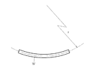
図1は、本実施形態におけるマーキング装置にてマーキングされる鋼線材Wを示した図である。この鋼線材Wは、長さおよそ300mmで、所定の曲率半径rで湾曲する断面円形の線材である。線径は5.5mm〜48mmの範囲で様々な径のものが存在する。この鋼線材Wは、熱間にて圧延された線材をコイル状に巻回して製造された線材コイル製品の端部を切断して得られたもので、外観検査、火花検査、呈色検査等に用いられる。
鋼線材Wは、コイル製品の本体から切り離された状態で取り扱われるため、切り離された直後に識別のため、数字やアルファベット文字からなるマーキングが施される。
Next, embodiments of the present invention will be described in detail with reference to the drawings.
FIG. 1 is a view showing a steel wire W marked by the marking device in the present embodiment. This steel wire W is a wire having a circular cross section that is approximately 300 mm long and curves with a predetermined radius of curvature r. There are various wire diameters in the range of 5.5 mm to 48 mm. This steel wire W is obtained by cutting an end portion of a wire coil product manufactured by winding a hot rolled wire into a coil shape, and includes an appearance inspection, a spark inspection, a color inspection, and the like. Used for.
Since the steel wire W is handled in a state of being separated from the main body of the coil product, immediately after being separated, marking made of numbers and alphabet letters is applied for identification.
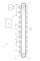
図2は、鋼線材Wにマーキングを行うためのマーキング装置10の全体構成を示した図である。同図において、12は鋼線材Wを保持した状態で図中右方向に搬送する搬送コンベア、14はレーザ照射部としてのレーザヘッド、16は搬送コンベア12及びレーザヘッド14の動作制御を行う制御部である。
FIG. 2 is a diagram showing an overall configuration of the
搬送コンベア12は、駆動モータ17(図6)、駆動モータ17に連結された一対の駆動ギア18、駆動ギア18とは搬送方向反対側に配置された一対の従動ギア20、更に駆動ギア18と従動ギア20との間に配設された一対の搬送チェーン22、を備えている。そして、駆動ギア18に連結された駆動モータ17の回転により搬送チェーン22が図中時計方向に回転し、図2において横長の長円形状をなした搬送チェーン22上側の搬送面22aは図中右方向に移動せしめられる。
The
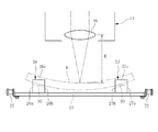
図3に示すように一対の搬送チェーン22の間には支持板24が設けられている。支持板24は平面形状が矩形の長手形状をなしており、それぞれの長手方向の各端部が、一対の搬送チェーン22のそれぞれに固定され、搬送チェーン22とともに一体に移動する。そして、支持板24の上面には、対称形状をなした一対の保持ブロック26,27が左右方向それぞれの端部近傍に取り付けられている。
これら一対の保持ブロック26,27は、図2に示すように、搬送方向に一定の間隔Pを隔てて多数並設されている。
As shown in FIG. 3, a
As shown in FIG. 2, a large number of the pair of holding
図4は、図3において支持板24の左側に取り付けられている保持ブロック26を単独で示した図である。保持ブロック26は全体が直方体形状をなしており、支持板24に取り付けた際の左右方向外側の側壁26aから中心側の側壁26bに亘って、上面26cで開口したV字溝30が形成されている。上面の開口を通じてV字溝30に収容された鋼線材Wは、2点鎖線で示すように、その下方側の外周面がV字溝30の斜面30a,30bに当接することで位置保持される。
FIG. 4 is a view independently showing the holding
また、同図(D)に示すように、V字溝30は、側壁26aから側壁26bに向かって、即ち、取り付け状態において、搬送コンベア12の中心部に向かって漸次溝深さが下向きに深くなるように形成されている。
Further, as shown in FIG. 4D, the V-shaped
尚、詳細な説明は省略するが、他方の保持ブロック27は、上記の保持ブロック26と左右対称の形状をなしており、図3で示すように、V字溝30は、側壁27aから側壁27bに向かって、即ち、取り付け状態において、搬送コンベア12の左右方向の中心部に向かって漸次溝深さが下向きに深くなるように形成されている。
Although the detailed description is omitted, the other holding
図3に示すように、保持ブロック26,27を用いて保持される鋼線材Wは湾曲形状であるため、鋼線材Wを安定した状態である下向きに凸の状態で保持した時、その端部は搬送コンベア12の中心部に向かって斜め下向きに延びることから、本例では鋼線材Wの傾きに合わせて、V字溝30の溝深さを、搬送コンベア12の中心部に向かって漸次下向きに深くすることで、鋼線材Wの外周面と保持ブロック26,27の側壁との当接長を軸方向に長く確保することができる。若しくは、鋼線材Wの外周面と保持ブロック26,27の側壁との間に生じる隙間を小さくすることができる。このため、保持ブロック26,27で保持した際、鋼線材Wのがたつきを抑えることができる。
As shown in FIG. 3, since the steel wire W held using the holding blocks 26 and 27 has a curved shape, when the steel wire W is held in a downwardly convex state, which is a stable state, its end portion Is extended obliquely downward toward the center of the
図2において、搬送面22aの最も右端、レーザヘッド14直下の位置がレーザ照射位置である。搬送コンベア12では、搬送面22a上の保持ブロック26,27が順次、レーザ照射位置にまで移動する。
32は、レーザヘッド14の下方に設けられた第1のワーク検出センサである。この第1のワーク検出センサ32は、レーザ照射位置まで移動してきた保持ブロック26,27について、鋼線材Wを保持しているか否かを検出する。第1のワーク検出センサ32が鋼線材Wを検出すると、搬送コンベア12が位置停止している状態で、図3で示すようにレーザ照射位置にある鋼線材Wに対してレーザが照射され、鋼線材Wの外周面、詳しくは鋼線材Wの軸方向の中間位置における、レーザヘッド14と対向する上面にマーキングが施される。
In FIG. 2, the rightmost end of the
また本例では、レーザ照射位置よりも1ピッチ(P)分上流側の位置を予備検出位置とし、この予備検出位置にある保持ブロック26,27について鋼線材Wの有無を検出する第2のワーク検出センサ34が設けられている。後述するように、この第2のワーク検出センサ34は、レーザ照射位置にある第1のワーク検出センサ32におけるワーク(鋼線材W)の未検出や誤検出といった異常を検出するために用いられるものである。
Further, in this example, a position that is one pitch (P) upstream from the laser irradiation position is set as a preliminary detection position, and the second workpiece for detecting the presence or absence of the steel wire W in the holding blocks 26 and 27 at the preliminary detection position. A
図5は、レーザ照射部としてのレーザヘッド14の構成を示した図である。40はレーザ光源としてのレーザ発振器で、本例ではYAGレーザが用いられている。42はレーザ光の焦点距離を調整するための焦点距離調整手段、44はレーザ光をX方向及びY方向に走査するための走査手段、46はレーザ光を集光するための集光レンズである。
FIG. 5 is a diagram showing a configuration of a
焦点距離調整手段42は、入射レンズ48、出射レンズ49、更に入射レンズ48を出射レンズ49に対し接近離間方向に移動させる入射レンズ移動モータ50を備えている。焦点距離調整手段42では入射レンズ48と出射レンズ49との間の距離を変化させることで、レーザヘッド14、詳しくは集光レンズ46から出射されるレーザ光の焦点距離Sを変更させることができる。
The focal
走査手段44は、ガルバノミラー52及びこれを回転駆動させるための走査用モータ54を、X方向及びY方向についてそれぞれ一式ずつ備えている。本例では指定されたマーキングの内容に応じて、走査手段44を作動させることで、鋼線材Wの表面でのレーザ光をX方向及びY方向に位置移動させ、所定のマーキング内容が鋼線材Wの表面に印字される。
The
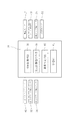
図6はマーキング装置10の制御系のブロック図である。搬送コンベア12及びレーザヘッド14の動作制御を行う制御部16は、情報取得手段56、焦点距離導出手段58、異常判定手段60、記憶部61を備えており、例えばCPU、RAM、HDD、及び各種インターフェイスを備えた情報処理装置や、専用のハードウェアを用いて構成することができる。
この制御部16には、第1のワーク検出センサ32、第2のワーク検出センサ34、ホストコンピュータ62、搬送コンベア12の駆動モータ17、レーザ発振器40、入射レンズ移動モータ50、走査用モータ54が接続されている。
FIG. 6 is a block diagram of a control system of the marking
The
情報取得手段56は、線材コイル製品を製造している工程を管理しているホストコンピュータ62のデータベースから線径情報およびマーキング内容の情報を取得する。本例では、前工程で製造された順に線材コイル製品の端部を切断し、得られた鋼線材Wをその順番でマーキング装置10にセットする。このため、線径情報およびマーキング内容の情報についても線材コイル製品が製造された順にデータベースから取得する。
The information acquisition means 56 acquires wire diameter information and marking content information from the database of the
焦点距離導出手段58は、得られた鋼線材Wの線径情報に基づいて、マーキングに適したレーザ光の焦点距離を導出する。本例では、保持ブロック26,27で保持された鋼線材Wの外表面に対してマーキングを行うが、線径が変化すると、図3で示す集光レンズ46から鋼線材Wの外表面までの距離Kが変化するため、レーザ光の焦点距離Sを変更する必要が生じる。
焦点距離導出手段58では、予め鋼線材Wの線径毎に明瞭に印字可能な焦点距離Sを調査して、鋼線材Wの線径と焦点距離Sとの関係を記憶部61に格納しておき、上記情報取得手段56にて取得された鋼線材Wの線径情報に対応する焦点距離Sの値を記憶部61から取り出すことで目的とする焦点距離Sを得ることができる。
The focal length deriving means 58 derives the focal length of the laser beam suitable for marking based on the obtained wire diameter information of the steel wire W. In this example, marking is performed on the outer surface of the steel wire W held by the holding blocks 26 and 27, but when the wire diameter changes, from the
In the focal length deriving means 58, the focal length S that can be clearly printed for each wire diameter of the steel wire W is investigated in advance, and the relationship between the wire diameter of the steel wire W and the focal length S is stored in the
以上のように構成されたマーキング装置10において、マーキングを行う基本的な手順は以下の通りである。まず、前工程で製造されたコイル製品の端部を切断して得られた鋼線材Wを、搬送コンベア12の保持ブロック26,27にセットする。
鋼線材Wは保持ブロック26,27にて保持された状態で搬送され、レーザヘッド14の直下のレーザ照射位置に到達すると、第1のワーク検出センサ32が鋼線材Wを検出し、搬送コンベア12はその状態(鋼線材Wがレーザ照射位置にある状態)で停止する。制御部16はホストコンピュータ62のデータベースから取得した線径の情報に基づいて、レーザ光の焦点距離Sを導出し、レーザヘッド14におけるレーザ光の焦点距離Sが調整される。次にレーザ光がレーザ発振器40から出射され、鋼線材Wの表面に照射されたレーザ光は、鋼線材Wの表面の一部をスポット溶解させる。この際、取得したマーキング内容の情報に応じて走査手段44が制御される。その結果、照射位置が移動して、鋼線材Wの表面に所定のマーキング内容が印字される。
In the marking
The steel wire W is transported while being held by the holding blocks 26 and 27. When the steel wire W reaches the laser irradiation position directly below the
マーキングが完了すると搬送コンベア12は搬送を再開する。そして、新たな鋼線材Wがレーザ照射位置に到達すると、上記と同様に焦点距離の調整が行なわれ、その後レーザ光が照射されマーキングが行なわれる。
When marking is completed, the
尚、上述のように本例では、レーザ照射位置の鋼線材Wを検出する第1のワーク検出センサ32の検出結果に基づいてマーキングが実行されため、第1のワーク検出センサ32の検出結果に誤りがあると、マーキングされる鋼線材Wとそのマーキング内容との不一致が生じるおそれがある。これを防止するため本例では、制御部16に異常判定手段60を設け、第1のワーク検出センサ32の鋼線材有無情報と、事前に予備検出位置で取得された第2のワーク検出センサ34の鋼線材有無情報とを比較し、一致していない場合は異常と判定し、警報を発するとともにマーキング動作を中止する。
As described above, in this example, since marking is performed based on the detection result of the first
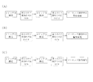
例えば、図7(A)で示すように、ある保持ブロックが予備検出位置にあったとき第2のワーク検出センサ34がON(ワーク有り)であったにも拘らず、搬送コンベア12が1ピッチ(P)分移動し、レーザ照射位置に到達した際、第1のワーク検出センサ32がOFF(ワーク無し)であった場合は、第1のワーク検出センサ32が存在しているワーク(鋼線材W)を検出できていなかった未検出の可能性が高いため、マーキングを中止するとともに警報を発して、オペレータに確認を促す。
For example, as shown in FIG. 7 (A), when a certain holding block is in the preliminary detection position, the
また図7(B)に示すように、ある保持ブロックが予備検出位置にあったとき第2のワーク検出センサ34がOFFであったにも拘らず、搬送コンベア12が1ピッチ分移動し、レーザ照射位置に到達した際、第1のワーク検出センサ32がONであった場合は、第1のワーク検出センサ32が他の部品(又は別の鋼線材)を誤って検出してしまった誤検出の可能性が高いため、マーキングを中止するとともに警報を発して、オペレータに確認を促す。
As shown in FIG. 7B, when a certain holding block is at the preliminary detection position, the
尚、図7(C)に示すように、ある保持ブロックが予備検出位置にあったとき第2のワーク検出センサ34がONであり、搬送コンベア12が1ピッチ(P)分移動し、レーザ照射位置に到達した際、第1のワーク検出センサ32もONである場合は、2つのセンサの検出結果が一致しているため、引き続きマーキングの動作が実行される。
As shown in FIG. 7C, when a certain holding block is at the preliminary detection position, the second
以上のように本実施形態によれば、レーザ光により鋼線材Wの表面をスポット溶解させてマーキングを施すため、鋼線材Wに対して実質的に無負荷で印字を行なうことができる。このためマーキングの際、下向きの打刻力により鋼線材Wが左右方向に逃げてしまうといった問題が生じることはなく、線径の細い鋼線材Wに対しても明瞭なマーキングを施すことができる。また強い力で鋼線材Wを位置固定する必要がなくなるため、搬送用の保持ブロック26,27に鋼線材Wを載せたままの状態でマーキングを行なうことができる。 As described above, according to the present embodiment, the surface of the steel wire W is spot-dissolved by the laser beam to perform marking, so that the steel wire W can be printed with substantially no load. For this reason, there is no problem that the steel wire W escapes in the left-right direction due to the downward punching force at the time of marking, and clear marking can be applied to the steel wire W having a small wire diameter. Further, since it is not necessary to fix the position of the steel wire W with a strong force, the marking can be performed in a state where the steel wire W is placed on the holding blocks 26 and 27 for conveyance.
本実施形態では、マーキング対象の鋼線材Wの線径情報に基づいて、マーキングに適したレーザ光の焦点距離を導出する焦点距離導出手段58を設け、導出結果に基づいてレーザヘッド14に設けた焦点距離調整手段42を作動させ、レーザ光の焦点距離を自動調整する。このため、線径が異なる鋼線材Wが混在している場合であっても、各鋼線材毎にレーザ光の焦点距離を変更させて、マーキングを行うことができる。
In the present embodiment, the focal length deriving means 58 for deriving the focal length of the laser beam suitable for marking is provided based on the wire diameter information of the steel wire W to be marked, and the
本実施形態では、マーキング対象の鋼線材Wの線径情報及びマーキング内容の情報を、外部のベータベースから取得する情報取得手段56が、制御部16に設けられており、前工程で順次製造されたコイル製品の端部を切断して得られた鋼線材Wを、その順番のままマーキングする場合、前工程を管理しているホストコンピュータ62のデータベースから線径情報およびマーキング内容の情報を製造順に取得するようにすれば、オペレータが改めて線径情報およびマーキング内容の情報をマーキング装置10に入力する作業を不要とすることができ、作業性が向上するとともに入力ミスによる品質トラブルを防止することができる。
In this embodiment, the information acquisition means 56 which acquires the wire diameter information and marking content information of the steel wire W to be marked from the external beta base is provided in the
また本実施形態では、現在、レーザ照射位置にある保持ブロック26,27について第1のワーク検出センサ32の鋼線材有無情報と、事前に予備検出位置で取得された第2のワーク検出センサ34の鋼線材有無情報とを比較し、一致していない場合を異常と判定する異常判定手段60が、制御部16に設けてあり、レーザ照射位置にある保持ブロック26,27において、ワークの未検出(有るばずのワークを無しと判断)や誤検出(無いはずのワークを有りと判断)の可能性がある場合、マーキング動作を停止させて品質トラブルを未然に防止することができる。
In the present embodiment, the steel wire rod presence / absence information of the first
また本実施形態では、鋼線材Wを保持する保持ブロック26,27に、上面が開口したV字溝30を形成するとともに、このV字溝30を搬送コンベア12の左右方向の中心部に向かって漸次溝深さが深くなるように形成しているため、マーキング対象の鋼線材Wが円弧状に湾曲した形状であった場合に、鋼線材Wを下向きに凸の状態で良好に保持することができる。
Moreover, in this embodiment, while forming the V-shaped groove |
以上本発明の実施形態を詳述したがこれはあくまで一例示である。上記実施形態では湾曲した鋼線材Wにマーキングを施したが、直線状に延びる鋼線材Wに対して適用することも可能である等、本発明はその趣旨を逸脱しない範囲において種々変更を加えた態様で実施可能である。 Although the embodiment of the present invention has been described in detail above, this is merely an example. In the above embodiment, the curved steel wire W is marked. However, the present invention can be applied to the steel wire W extending in a straight line, and the present invention has various modifications without departing from the spirit of the invention. It can be implemented in an embodiment.
10 マーキング装置
12 搬送コンベア
14 レーザヘッド(レーザ照射部)
16 制御部
26,27 保持ブロック
30 V字溝
32 第1のワーク検出手段
34 第2のワーク検出手段
42 焦点距離調整手段
56 情報取得手段
58 焦点距離導出手段
60 異常判定手段
DESCRIPTION OF
DESCRIPTION OF
Claims (5)
前記搬送コンベアの搬送方向の下流側で、かつ、前記鋼線材の上方に配設されたレーザ照射部と、
これら搬送コンベア及びレーザ照射部の動作制御を行う制御部と、を備え、
前記一対の保持ブロックで保持された状態の前記鋼線材の表面にレーザ光を照射して、マーキングを行なうように構成されていることを特徴とするマーキング装置。 A transport conveyor in which a plurality of left and right holding blocks for holding the steel wire are arranged in parallel in the transport direction;
A laser irradiation unit disposed on the downstream side of the transport direction of the transport conveyor and above the steel wire;
A control unit for controlling the operations of the conveyor and the laser irradiation unit,
A marking device configured to perform marking by irradiating a surface of the steel wire held by the pair of holding blocks with a laser beam.
また前記制御部は、前記マーキング対象の鋼線材の線径情報に基づいて、前記レーザ光の焦点距離を導出する焦点距離導出手段を備え、
該焦点距離導出手段の導出結果に基づいて前記焦点距離調整手段を作動させ、前記レーザ光の焦点距離を自動調整するように構成されていることを特徴とする請求項1に記載のマーキング装置。 The laser irradiation unit includes a focal length adjustment unit that adjusts a focal length of the laser light,
In addition, the control unit includes a focal length deriving unit that derives the focal length of the laser light based on the wire diameter information of the steel wire to be marked.
2. The marking apparatus according to claim 1, wherein the focal length adjusting unit is operated based on a result derived by the focal length deriving unit to automatically adjust the focal length of the laser beam.
前記レーザ照射位置よりも上流側に設定された予備検出位置にある前記保持ブロックについて前記鋼線材の有無を検出する第2のワーク検出センサと、が設けられており、
前記制御部は、前記レーザ照射位置にある前記保持ブロックについての、第1のワーク検出センサの鋼線材有無情報と、事前に予備検出位置で取得された前記第2のワーク検出センサの鋼線材有無情報とを比較し、一致していない場合を異常と判定する異常判定手段を備えていることを特徴とする請求項1〜3の何れかに記載のマーキング装置。 A first work detection sensor that detects the presence or absence of the steel wire rod for the holding block at the laser irradiation position on the conveyor,
A second workpiece detection sensor that detects the presence or absence of the steel wire rod for the holding block at the preliminary detection position set upstream from the laser irradiation position; and
The control unit includes the steel wire material presence / absence information of the first work detection sensor and the steel wire material presence / absence of the second work detection sensor acquired in advance at the preliminary detection position for the holding block at the laser irradiation position. The marking device according to claim 1, further comprising an abnormality determination unit that compares information with each other and determines that the information does not match as abnormal.
Priority Applications (1)
| Application Number | Priority Date | Filing Date | Title |
|---|---|---|---|
| JP2016088428A JP6701921B2 (en) | 2016-04-26 | 2016-04-26 | Marking device |
Applications Claiming Priority (1)
| Application Number | Priority Date | Filing Date | Title |
|---|---|---|---|
| JP2016088428A JP6701921B2 (en) | 2016-04-26 | 2016-04-26 | Marking device |
Publications (2)
| Publication Number | Publication Date |
|---|---|
| JP2017196635A true JP2017196635A (en) | 2017-11-02 |
| JP6701921B2 JP6701921B2 (en) | 2020-05-27 |
Family
ID=60237037
Family Applications (1)
| Application Number | Title | Priority Date | Filing Date |
|---|---|---|---|
| JP2016088428A Active JP6701921B2 (en) | 2016-04-26 | 2016-04-26 | Marking device |
Country Status (1)
| Country | Link |
|---|---|
| JP (1) | JP6701921B2 (en) |
Cited By (1)
| Publication number | Priority date | Publication date | Assignee | Title |
|---|---|---|---|---|
| JP2019084577A (en) * | 2017-11-09 | 2019-06-06 | 東芝テック株式会社 | Marking device and marking system |
-
2016
- 2016-04-26 JP JP2016088428A patent/JP6701921B2/en active Active
Cited By (2)
| Publication number | Priority date | Publication date | Assignee | Title |
|---|---|---|---|---|
| JP2019084577A (en) * | 2017-11-09 | 2019-06-06 | 東芝テック株式会社 | Marking device and marking system |
| JP7163016B2 (en) | 2017-11-09 | 2022-10-31 | 東芝テック株式会社 | Marking device and marking system |
Also Published As
| Publication number | Publication date |
|---|---|
| JP6701921B2 (en) | 2020-05-27 |
Similar Documents
| Publication | Publication Date | Title |
|---|---|---|
| TWI680821B (en) | Laser processing device | |
| JP6388823B2 (en) | Laser processing equipment | |
| JP5108518B2 (en) | Method for obtaining mutual position of laser processing beam axis and processing gas flow axis in laser processing apparatus, method for adjusting mutual position of laser processing beam axis and processing gas flow axis in laser processing apparatus, and apparatus in place of this method Laser processing apparatus having | |
| KR102322716B1 (en) | Wafer processing method | |
| JP2008246660A (en) | Workpiece machining machine | |
| WO2019107344A1 (en) | Long film laser machining method | |
| CN108356422B (en) | Online measurement, waste falling and finished product separation identification method for continuous laser blanking of strip coil | |
| CN112020404A (en) | Workpiece machining device, in particular a panel dividing saw, method for operating a workpiece machining device and control device | |
| CN105081559A (en) | Laser processing apparatus | |
| CN115734845A (en) | Workpiece processing device and method for operating a workpiece processing device | |
| JP5649770B2 (en) | Mechanical sheet making equipment | |
| JP2017196635A (en) | Marking device | |
| JP2018015903A (en) | Scribing method and scribing device | |
| JP2006505417A (en) | Guide device | |
| GB2318885A (en) | automatically following a joint line which is to be welded | |
| JP2017135132A (en) | Laser processing device | |
| CN112074368A (en) | Workpiece processing device, method and control device for operating a workpiece processing device | |
| JP4343763B2 (en) | End edge processing apparatus and processing state inspection method | |
| JP5672395B2 (en) | Steel plate removal system and method | |
| KR101678985B1 (en) | Laser processing apparatus and laser processing method using the laser processing apparatus | |
| JP2023518747A (en) | Method and apparatus for determining the actual condition of the support bars of the base material support, and machine tools having such apparatus | |
| JP2013132646A (en) | Laser cutting method and apparatus | |
| CN116348236A (en) | Method for welding sheet metal parts | |
| KR101948684B1 (en) | Defective products processing system and method of processing defective products using the same | |
| KR20170029381A (en) | Laser processing device |
Legal Events
| Date | Code | Title | Description |
|---|---|---|---|
| A521 | Written amendment |
Free format text: JAPANESE INTERMEDIATE CODE: A821 Effective date: 20160427 |
|
| RD04 | Notification of resignation of power of attorney |
Free format text: JAPANESE INTERMEDIATE CODE: A7424 Effective date: 20170424 |
|
| A621 | Written request for application examination |
Free format text: JAPANESE INTERMEDIATE CODE: A621 Effective date: 20190220 |
|
| A977 | Report on retrieval |
Free format text: JAPANESE INTERMEDIATE CODE: A971007 Effective date: 20200115 |
|
| A131 | Notification of reasons for refusal |
Free format text: JAPANESE INTERMEDIATE CODE: A131 Effective date: 20200204 |
|
| A521 | Written amendment |
Free format text: JAPANESE INTERMEDIATE CODE: A523 Effective date: 20200319 |
|
| A521 | Written amendment |
Free format text: JAPANESE INTERMEDIATE CODE: A523 Effective date: 20200326 |
|
| TRDD | Decision of grant or rejection written | ||
| A01 | Written decision to grant a patent or to grant a registration (utility model) |
Free format text: JAPANESE INTERMEDIATE CODE: A01 Effective date: 20200407 |
|
| A61 | First payment of annual fees (during grant procedure) |
Free format text: JAPANESE INTERMEDIATE CODE: A61 Effective date: 20200420 |
|
| R150 | Certificate of patent or registration of utility model |
Ref document number: 6701921 Country of ref document: JP Free format text: JAPANESE INTERMEDIATE CODE: R150 |