JP2017196323A - Stirring unit - Google Patents

Stirring unit Download PDF

Info

Publication number
JP2017196323A
JP2017196323A JP2016091830A JP2016091830A JP2017196323A JP 2017196323 A JP2017196323 A JP 2017196323A JP 2016091830 A JP2016091830 A JP 2016091830A JP 2016091830 A JP2016091830 A JP 2016091830A JP 2017196323 A JP2017196323 A JP 2017196323A
Authority
JP
Japan
Prior art keywords
stirring
milk
liquid
milk preparation
protrusion
Prior art date
Legal status (The legal status is an assumption and is not a legal conclusion. Google has not performed a legal analysis and makes no representation as to the accuracy of the status listed.)
Pending
Application number
JP2016091830A
Other languages
Japanese (ja)
Inventor
基也寿 芳井
Motoyasu Yoshii
基也寿 芳井
俊範 岡田
Toshinori Okada
俊範 岡田
高橋 大輔
Daisuke Takahashi
大輔 高橋
木路 仁
Hitoshi Kiji
仁 木路
正明 児玉
Masaaki Kodama
正明 児玉
惇 後藤
Atsushi Goto
惇 後藤
慎二 長井
Shinji Nagai
慎二 長井
Current Assignee (The listed assignees may be inaccurate. Google has not performed a legal analysis and makes no representation or warranty as to the accuracy of the list.)
Sharp Corp
Original Assignee
Sharp Corp
Priority date (The priority date is an assumption and is not a legal conclusion. Google has not performed a legal analysis and makes no representation as to the accuracy of the date listed.)
Filing date
Publication date
Application filed by Sharp Corp filed Critical Sharp Corp
Priority to JP2016091830A priority Critical patent/JP2017196323A/en
Publication of JP2017196323A publication Critical patent/JP2017196323A/en
Pending legal-status Critical Current

Links

Images

Abstract

PROBLEM TO BE SOLVED: To provide a powdery milk formula device that can be readily handled and inhibit loss of synchronism of a stirring element.SOLUTION: In a stirring unit, a lid part (8a) provided in an opening part of a milk formula pot (4) includes a projection part (81) projecting toward a rotation center of a stirring element (4a). The projection part (81) is positioned upward of the stirring element (4a) so as to have an interval to the stirring element (4a) while the stirring element (4a) is disposed in a bottom part of the milk formula pot (4).SELECTED DRAWING: Figure 1

Description

本発明は、液体を受容する撹拌容器と、該撹拌容器の底部に配される撹拌子とを備える撹拌ユニットに関する。特に、本発明は、混合物用原料と液体とを混合して液体混合物を調製する撹拌ユニットに関する。   The present invention relates to a stirring unit including a stirring container for receiving a liquid and a stirring bar arranged at the bottom of the stirring container. In particular, the present invention relates to a stirring unit that prepares a liquid mixture by mixing a mixture raw material and a liquid.

近年、WHO(世界保健機関:World Health Organization)とFAO(国連食糧農業機関:Food and Agriculture Organization of the United Nations)とによって、「乳児用乾燥粉末乳の安全な調乳、保存及び取扱いに関するガイドライン」が共同作成された。   In recent years, WHO (World Health Organization) and FAO (Food and Agriculture Organization of the United Nations) "Guidelines on Safe Formulation, Storage and Handling of Dry Powdered Milk for Infants" Was co-created.

このガイドラインによれば、乳児用乾燥粉末乳つまり乳児用の粉ミルクと、エンテロバクター・サカザキ等への感染による乳児の重篤な疾患や死亡との関連が報告されている。   According to this guideline, there is a report on the relationship between infant dry milk powder, that is, infant formula, and severe illness and death of infants due to infection with Enterobacter Sakazaki, etc.

上記感染への防止対策として、乳児に与える乾燥粉末乳は、沸騰させた水を70℃以上の温度で用いて調乳されなければならないと報告されている。具体的な調乳方法として、ガイドラインには以下の方法が記載されている。
(1)乾燥粉末乳(粉ミルク)を調乳するところの表面を清掃し消毒する。
(2)石鹸と清浄な水とで手指を洗い、清潔な布又は使い捨てのナプキンを用いて水分を拭き取る。
(3)十分な量の安全な水を沸騰させる。
(4)火傷に気をつけて、70℃以上にまで冷却した適量の沸騰させた水を、清潔で滅菌済みのコップ又は哺乳ビンに注ぐ。
(5)表示された量の乾燥粉末乳を正確に量って加える。
(6)水道の流水の下に置くか、冷水又は氷水の入った容器に静置することにより、授乳に適した温度まで短時間で冷却する。
(7)哺乳用コップ又は哺乳ビンの外側を清潔な布又は使い捨ての布で拭き、乾燥粉末乳の種類、乳児の名前若しくは識別番号、調乳した日付と時刻、又は調乳した職員の名前等の必要な情報を表示する。
(8)非常に高温の湯が調乳に使用されるため、乳児の口に火傷を負わさないよう、授乳する前に授乳温度を確認することが不可欠である。
(9)調乳後2時間以内に消費されなかった乾燥粉末乳は、全て廃棄すること。
As a preventive measure against the above infection, it has been reported that dry powdered milk given to infants must be prepared using boiling water at a temperature of 70 ° C. or higher. As specific milk preparation methods, the guidelines describe the following methods.
(1) Clean and disinfect the surface where dry powdered milk (milk powder) is prepared.
(2) Wash fingers with soap and clean water and wipe off moisture with a clean cloth or disposable napkin.
(3) Boil a sufficient amount of safe water.
(4) Be careful of burns and pour an appropriate amount of boiled water cooled to above 70 ° C into a clean and sterilized cup or baby bottle.
(5) Accurately add the indicated amount of dry powdered milk.
(6) Cool in a short time to a temperature suitable for breastfeeding by placing it under running tap water or leaving it in a container containing cold or ice water.
(7) Wipe the outside of the feeding cup or bottle with a clean cloth or disposable cloth, the type of dry powdered milk, the name or identification number of the infant, the date and time of milk preparation, the name of the staff who prepared the milk, etc. Display the necessary information.
(8) Since very hot water is used for formulating, it is essential to check the feeding temperature before breast feeding so as not to burn the infant's mouth.
(9) Discard any dry powdered milk that has not been consumed within 2 hours of preparation.

ここで、乳児に与えるミルクの温度は、母乳の温度や体温等を勘案し、人肌温度である40℃程度が適温とされている。このため、乾燥粉末乳を調乳し、乳児に与えるミルクとするためには、70℃以上の一度沸騰させた液体を用いて調乳した後、ミルクを40℃程度にまで冷却する必要がある。   Here, the temperature of milk given to the infant is considered to be about 40 ° C., which is the human skin temperature, in consideration of the temperature and body temperature of breast milk. For this reason, in order to prepare dry powdered milk and give it to infants, it is necessary to cool the milk to about 40 ° C. after preparing using a liquid once boiled at 70 ° C. or higher. .

乳児用のミルクを調乳するための従来の装置及び方法としては、例えば特許文献1に開示されているミルクフォーマーが知られている。   As a conventional apparatus and method for preparing milk for infants, for example, a milk former disclosed in Patent Document 1 is known.

特許文献1に開示されているミルクフォーマーでは、撹拌機構は、撹拌ヘッドとこの撹拌ヘッドを支持するための軸部とを備え、前記撹拌ヘッドを磁気駆動するための磁気駆動機構がベース本体に備えられている。   In the milk foamer disclosed in Patent Document 1, the stirring mechanism includes a stirring head and a shaft portion for supporting the stirring head, and a magnetic drive mechanism for magnetically driving the stirring head is provided in the base body. Is provided.

国際公開第2014/136833号(2014年9月12日公開)International Publication No. 2014/136833 (Released on September 12, 2014)

特許文献1に開示されたミルクフォーマーが備える撹拌機構は、軸部がカップ蓋に回転可能に支持されていると共に、上記軸部に撹拌ヘッドが固定されており、縦長の複雑な構造体である。このため、ユーザーは、上記ミルクフォーマーのカップ体に対する上記撹拌機構の着脱、該撹拌機構の洗浄などを慎重に行う必要があり、取扱い(ユーザビリティ)に難点がある。一方、上記軸部を省略すると、上記撹拌ヘッドが上方へ移動して、脱調する虞がある。   The stirring mechanism provided in the milk foamer disclosed in Patent Document 1 has a shaft portion rotatably supported by the cup lid, and a stirring head fixed to the shaft portion, and is a vertically long complicated structure. is there. For this reason, it is necessary for the user to carefully attach and detach the stirring mechanism to and from the cup body of the milk foamer and to clean the stirring mechanism, and there is a difficulty in handling (usability). On the other hand, if the shaft portion is omitted, the stirring head may move upward and step out.

本発明は、上記問題点に鑑みてなされたものであり、その目的は、取扱いが容易であり、かつ脱調を抑制できる撹拌ユニットを提供することにある。   The present invention has been made in view of the above problems, and an object of the present invention is to provide a stirring unit that is easy to handle and can suppress step-out.

上記の課題を解決するために、本発明の一態様に係る撹拌ユニットは、液体を受容する撹拌容器と、該撹拌容器の底部に配され、外部からの磁力により上記液体を撹拌する撹拌子とを備える撹拌ユニットであって、上記撹拌子が上記底部から上方に移動することを規制する規制部材を備えており、該規制部材は、上記撹拌子が上記底部に配されている状態において、上記撹拌子の上方に位置し、かつ、上記撹拌子と間隙を有するように、上記撹拌容器に設けられていることを特徴としている。   In order to solve the above problems, a stirring unit according to one aspect of the present invention includes a stirring container that receives a liquid, and a stirring bar that is disposed at the bottom of the stirring container and stirs the liquid by an external magnetic force. A stirrer unit comprising a restricting member that restricts the stirrer from moving upward from the bottom, and the restricting member is in a state in which the stirrer is disposed at the bottom. It is characterized by being provided in the stirring vessel so as to be located above the stirring bar and have a gap with the stirring bar.

本発明の一態様によれば、取扱いが容易であり、かつ脱調を抑制できる撹拌ユニットを提供できるという効果を奏する。   According to one aspect of the present invention, it is possible to provide an agitation unit that is easy to handle and can suppress step-out.

(a)は、本発明の実施の形態1に係る粉末乳調乳装置の構成を示す断面図であり、(b)は、上記粉末乳調乳装置が備える調乳用ポットの構成を示す平面図である。(A) is sectional drawing which shows the structure of the powdered milk preparation apparatus which concerns on Embodiment 1 of this invention, (b) is a plane which shows the structure of the pot for milk preparation with which the said powdered milk preparation apparatus is equipped. FIG. 本発明の実施の形態1に係る粉末乳調乳装置のセッティング方法を示すフロー図である。It is a flowchart which shows the setting method of the powdered milk preparation apparatus which concerns on Embodiment 1 of this invention. 本発明の実施の形態1に係る粉末乳調乳装置の効果を説明するための図である。It is a figure for demonstrating the effect of the powdered milk preparation apparatus which concerns on Embodiment 1 of this invention. 本発明の実施の形態2に係る粉末乳調乳装置の構成およびセッティング方法を示すフロー図である。It is a flowchart which shows the structure and setting method of the powdered milk preparation apparatus which concern on Embodiment 2 of this invention. 本発明の実施の形態3に係る粉末乳調乳装置の構成およびセッティング方法を示すフロー図である。It is a flowchart which shows the structure and setting method of a powdered milk preparation apparatus which concern on Embodiment 3 of this invention. (a)は、本発明の実施の形態5に係る粉末乳調乳装置におけるミルクの混合状態を示す断面図であり、(b)は、比較例である粉末乳調乳装置におけるミルクの混合状態を示す断面図である。(A) is sectional drawing which shows the mixing state of the milk in the powdered milk preparation apparatus which concerns on Embodiment 5 of this invention, (b) is the mixed state of the milk in the powdered milk preparation apparatus which is a comparative example FIG. 各種の粉末乳調乳装置を用いて調乳した場合の、ミルクの温度と給湯開始からの経過時間との関係を示すグラフである。It is a graph which shows the relationship between the temperature of milk at the time of milking using various powdered milk formulating apparatuses, and the elapsed time from the hot-water supply start.

以下、本発明の実施形態について、詳細に説明する。なお、説明の便宜上、各実施形態に示した部材と同一の機能を有する部材については、同一の符号を付記し、適宜その説明を省略する。   Hereinafter, embodiments of the present invention will be described in detail. For convenience of explanation, members having the same functions as those shown in the embodiments are denoted by the same reference numerals, and description thereof is omitted as appropriate.

〔実施の形態1〕
本発明の一実施形態について図1〜図3に基づいて説明すれば、以下のとおりである。
[Embodiment 1]
An embodiment of the present invention will be described below with reference to FIGS.

本実施の形態では、液体(特に、混合物)を撹拌する撹拌ユニットとして、例えば、混合・抽出用原料としての乳児用の粉ミルクと加熱した液体とを自動で混合して混合物としてのミルクを生成する粉末乳調乳装置について説明する。なお、本発明の撹拌ユニットは、必ずしもこれに限らない。例えば、混合・抽出用原料としての挽きコーヒー豆に、加熱した液体を注いで混合物としてのコーヒーを自動で生成する撹拌ユニットとしてのコーヒーメーカーに本発明を適用することができる。その他、混合・抽出用原料としての茶葉に加熱した液体を注いで混合物としての日本茶又は紅茶を自動で生成する撹拌ユニットとしての茶メーカーに本発明を適用することができる。   In this embodiment, as a stirring unit that stirs a liquid (particularly, a mixture), for example, infant milk powder as a mixing / extraction raw material and heated liquid are automatically mixed to generate milk as a mixture. A powdered milk preparation device will be described. In addition, the stirring unit of this invention is not necessarily restricted to this. For example, the present invention can be applied to a coffee maker as a stirring unit that automatically generates a coffee as a mixture by pouring a heated liquid into ground coffee beans as a mixing / extraction raw material. In addition, the present invention can be applied to a tea maker as an agitation unit that automatically produces Japanese tea or black tea as a mixture by pouring a heated liquid into tea leaves as a raw material for mixing and extraction.

(粉末乳調乳装置1Aの構成)
本実施の形態の粉末乳調乳装置1A(撹拌ユニット)の構成について、図1〜図3に基づいて説明する。
(Configuration of powdered milk preparation device 1A)
The configuration of the powdered milk preparation device 1A (stirring unit) according to the present embodiment will be described with reference to FIGS.

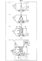
図1の(a)は、粉末乳調乳装置1Aの構成を示す断面図であり、(b)は、粉末乳調乳装置1Aが備える調乳用ポット4(撹拌容器)の構成を示す平面図である。図1の(a)に示すように、粉末乳調乳装置1Aは、筐体としての装置本体2と、液体を貯留する貯留容器3と、撹拌容器としての調乳用ポット4とから構成されている。   (A) of FIG. 1 is sectional drawing which shows the structure of 1 A of powdered milk preparation apparatuses, (b) is a plane which shows the structure of the pot 4 (stirring container) for milk preparation with which 1A of powdered milk preparation apparatuses is equipped. FIG. As shown to (a) of FIG. 1, 1 A of powdered milk preparation apparatuses are comprised from the apparatus main body 2 as a housing | casing, the storage container 3 which stores a liquid, and the pot for milk preparation 4 as a stirring container. ing.

(調乳用ポット4)
調乳用ポット4は、撹拌対象となる液体を受容する容器であり、装置本体2の載置部2aに載置され、調乳用ポット4の底部に配された撹拌子4aが回転することにより、調乳用ポット4の内部の液体が撹拌される。予め調乳用ポット4に内部に入れておいた乾燥粉末乳つまり粉ミルクMPとミルク生成用の煮沸済の液体Lとを調製混合することにより、ミルクMを生成することができる。
(Milk preparation pot 4)
The milk preparation pot 4 is a container that receives a liquid to be agitated, and is placed on the placement portion 2a of the apparatus main body 2, and the stirring bar 4a disposed on the bottom of the milk adjustment pot 4 rotates. Thus, the liquid inside the milk preparation pot 4 is stirred. Milk M can be generated by preparing and mixing dry powdered milk, that is, powdered milk MP, which has been put in the milk preparation pot 4 in advance, and a boiled liquid L for milk production.

この調乳用ポット4は、開口部41を覆うための蓋部8a(架設部)を備えている。蓋部8aには、装置本体2のノズル13と対向する部分に給湯用開口部82が形成されていると共に、排気口34へ通じる排気ダクト33bと対向する部分に排気用開口部83が形成されている。加熱された液体Lがノズル13から噴出し、給湯用開口部82を通って調乳用ポット4に供給される。液体Lの蒸気は、排気用開口部83および排気ダクト33bを通って、排気口34から排気される。   The milk preparation pot 4 includes a lid portion 8a (erection portion) for covering the opening 41. The lid portion 8a is formed with a hot water supply opening 82 at a portion facing the nozzle 13 of the apparatus body 2 and an exhaust opening 83 at a portion facing the exhaust duct 33b leading to the exhaust port 34. ing. The heated liquid L is ejected from the nozzle 13 and supplied to the milk preparation pot 4 through the hot water supply opening 82. The vapor of the liquid L is exhausted from the exhaust port 34 through the exhaust opening 83 and the exhaust duct 33b.

また、蓋部8aの中央部には、調乳用ポット4の底部に向かって突出する突出部81(規制部材)を備えている。より詳細には、突出部81は、撹拌子4aの回転中心に向けて突出している。突出部81は、先端部が細くなっており、突出部81の先端部が撹拌子4aと当接することにより、撹拌子4aが調乳用ポット4の底部から上方に移動することを規制する。   Moreover, the center part of the cover part 8a is provided with the protrusion part 81 (regulation member) which protrudes toward the bottom part of the pot 4 for milk preparation. More specifically, the protrusion 81 protrudes toward the rotation center of the stirring bar 4a. The protrusion 81 has a thin tip, and the tip of the protrusion 81 abuts on the stirrer 4 a to restrict the stirrer 4 a from moving upward from the bottom of the milk adjustment pot 4.

撹拌子4aが調乳用ポット4内の底部に配されている基準状態において、突出部81は、撹拌子4aの上方に位置し、かつ、撹拌子4aと間隙を有するように、調乳用ポット4に設けられている。また、蓋部8aは調乳用ポット4の開口部41に着脱可能に取り付けられるため、蓋部8aに設けられた突出部81も、開口部41に対して着脱可能に取り付けられる。   In the reference state where the stirrer 4a is disposed at the bottom of the milk preparation pot 4, the projecting portion 81 is located above the stirrer 4a and has a gap with the stirrer 4a. It is provided in the pot 4. Moreover, since the cover part 8a is detachably attached to the opening part 41 of the milk preparation pot 4, the protrusion part 81 provided in the cover part 8a is also detachably attached to the opening part 41.

なお、突出部81を支持する部材(架設部)は、開口部41に架設されるものであればよく、開口部41の蓋に限定されない。上記架設部は、例えば、開口部41に着脱可能で、開口部41に橋渡しされる細長い板状の部分を含む部材であってもよい。   In addition, the member (erection part) which supports the protrusion part 81 should just be constructed in the opening part 41, and is not limited to the lid | cover of the opening part 41. FIG. The bridge portion may be, for example, a member that is detachable from the opening 41 and includes an elongated plate-like portion that is bridged by the opening 41.

図1の(b)に示すように、撹拌子4aは、その内部に磁石40を有しており、磁石40の表面を樹脂で覆った形態となっている。表面に用いる樹脂は、食品用に適した樹脂を用いることが好ましく、例えば、シリコーン、テフロン(登録商標)系やポリプロピレンなどを用いることが望ましい。   As shown in FIG. 1 (b), the stir bar 4a has a magnet 40 therein, and the surface of the magnet 40 is covered with a resin. As the resin used for the surface, a resin suitable for food is preferably used. For example, silicone, Teflon (registered trademark), polypropylene, or the like is preferably used.

撹拌子4aの形状としては、細長い繭状のもの、八角棒状のもの、円盤状のもの、風車の羽根状のものなど様々なもので対応可能である。本実施の形態では、撹拌子4aは円盤状であり、調乳用ポット4の底部と対向する面に一対の突起を有している。   As the shape of the stirrer 4a, various shapes such as an elongated bowl shape, an octagonal rod shape, a disk shape, and a windmill blade shape can be used. In the present embodiment, the stirring bar 4a has a disc shape, and has a pair of protrusions on the surface facing the bottom of the milk preparation pot 4.

撹拌子4aの磁石40は、調乳用ポット4の下方の装置本体2の内部に配置されるモーター5の回転軸に配置された図示しない磁石と磁気結合するようになっている。それゆえ、撹拌子4aは、磁力により、モーター5の回転に同期して撹拌子4aが回転することになる。なお、調乳用ポット4内の底部から突出部81の先端部までの距離、すなわち、撹拌子4aの高さと、撹拌子4aおよび突出部81の間隙との和は、撹拌子4aが上方に移動して突出部81の先端部と当接しても、上記同期が維持できるような距離であることが望ましい。   The magnet 40 of the stirrer 4a is magnetically coupled to a magnet (not shown) arranged on the rotation shaft of the motor 5 arranged inside the apparatus main body 2 below the milk adjustment pot 4. Therefore, the stirring bar 4a is rotated in synchronization with the rotation of the motor 5 by the magnetic force. The distance from the bottom of the milk preparation pot 4 to the tip of the protrusion 81, that is, the sum of the height of the stirrer 4a and the gap between the stirrer 4a and the protrusion 81 is such that the stirrer 4a is upward. It is desirable that the distance be such that the above synchronization can be maintained even if it moves and abuts against the tip of the protrusion 81.

(貯留容器3)
貯留容器3は、装置本体2の上部に配置されていると共に、装置本体2に対して着脱可能となっている。貯留容器3には、調乳に用いるための液体Lが貯留される。液体Lとして、例えば、水道水の他、赤ちゃん用の飲用水、純水又は天然水といった赤ちゃんが飲むのに適した水等が挙げられる。
(Reservoir 3)
The storage container 3 is disposed on the upper part of the apparatus main body 2 and is detachable from the apparatus main body 2. The storage container 3 stores a liquid L for use in milk preparation. Examples of the liquid L include tap water, water suitable for babies such as drinking water for babies, pure water, and natural water.

また、貯留容器3の下部には給水弁3aが設けられており、貯留容器3を本体から取り外したときには給水弁3aが閉まる。このため、貯留容器3を装置本体2から取り外して水道から給水すること、および給水後持ち運びをすることができる。その後、貯留容器3を装置本体2に設置すると給水弁3aは開き、供給配管10およびヒーター12に液体Lが供給される。   Moreover, the water supply valve 3a is provided in the lower part of the storage container 3, and when the storage container 3 is removed from the main body, the water supply valve 3a is closed. For this reason, the storage container 3 can be removed from the apparatus main body 2 and supplied with water, and can be carried after the supply. Thereafter, when the storage container 3 is installed in the apparatus main body 2, the water supply valve 3 a is opened, and the liquid L is supplied to the supply pipe 10 and the heater 12.

貯留容器3の側面には水量を把握できるように目盛りが付けられており、ユーザーは、この目盛を用いて調乳量を調節することができる。なお、目盛りは貯留容器3の内側側面に付けてもよいし、貯留容器3を透明にして外側から確認できるようにしてもよい。   A scale is attached to the side surface of the storage container 3 so that the amount of water can be grasped, and the user can adjust the amount of milk preparation using this scale. The scale may be attached to the inner side surface of the storage container 3, or the storage container 3 may be transparent so that it can be confirmed from the outside.

また、貯留容器3には、例えば図示しない活性炭やイオン交換膜からなるフィルタ等を設置し、注がれた液体L内の不純物や塩素、バクテリアや細菌、イオン系金属類等の成分を除去可能とする構成としてもよい。さらに、液体Lを長時間貯留することを想定して、例えば紫外線照射装置等の殺菌装置を貯留容器3の上部に設置してもよい。これにより、貯留する液体Lに紫外線を照射し、殺菌することができる。   In addition, the storage container 3 is provided with, for example, a filter made of activated carbon or an ion exchange membrane (not shown) to remove impurities, chlorine, bacteria, bacteria, ionic metals, and the like in the poured liquid L. It is good also as a structure. Further, assuming that the liquid L is stored for a long time, for example, a sterilizer such as an ultraviolet irradiation device may be installed on the upper portion of the storage container 3. Thereby, the stored liquid L can be irradiated with ultraviolet rays and sterilized.

(装置本体2の構成)
装置本体2は、主な構成要素として、モーター5、操作パネル6、制御部7、供給配管10、フロート式逆止弁11およびヒーター12を備えている。
(Configuration of the apparatus body 2)
The apparatus main body 2 includes a motor 5, an operation panel 6, a control unit 7, a supply pipe 10, a float type check valve 11 and a heater 12 as main components.

モーター5は上述のように磁石を具備しており、モーター5が回転することで上記磁石が回転し、この回転によって撹拌子4aが回転する。そのため、モーター5は、撹拌子4aを回転させる回転機構としての機能を有している。   The motor 5 includes a magnet as described above. When the motor 5 rotates, the magnet rotates, and the stirrer 4a rotates by this rotation. Therefore, the motor 5 has a function as a rotation mechanism that rotates the stirring bar 4a.

モーター5は、粉末乳調乳装置1Aにおける、調乳用ポット4へ液体Lを滴下する動作とは独立して制御される。すなわち、液体Lの滴下時にモーター5が動いていてもよいし、停まっていてもよい。加えて、モーター5の回転方向および回転速度は可変となっており、ミルクMを生成する際に制御部7により上記回転方向および回転速度を適時制御してもよい。モーター5の制御を介して撹拌子4aの回転方向と回転速度とを制御することができる。   The motor 5 is controlled independently of the operation of dropping the liquid L onto the milk preparation pot 4 in the powder milk preparation device 1A. That is, the motor 5 may move or may stop when the liquid L is dropped. In addition, the rotation direction and the rotation speed of the motor 5 are variable, and when the milk M is generated, the control unit 7 may control the rotation direction and the rotation speed as appropriate. Through the control of the motor 5, the rotation direction and the rotation speed of the stirring bar 4a can be controlled.

また、モーター5への給電系統には電流検知回路が設けられていることが好ましい。撹拌子4aが配置されていない状態でミルクMを生成する場合や、撹拌子4aが何らかの異常によりモーター5の磁石との位置ずれを起こした場合には、モーター5への負荷が減少する。この負荷の減少を電流検知回路によって検出することにより、粉末乳調乳装置1Aの動作の異常を検出することができる。   In addition, a current detection circuit is preferably provided in the power supply system to the motor 5. When the milk M is generated in a state where the stirrer 4a is not disposed, or when the stirrer 4a is misaligned with the magnet of the motor 5 due to some abnormality, the load on the motor 5 is reduced. By detecting this decrease in load by the current detection circuit, it is possible to detect an abnormality in the operation of the powdered milk preparation device 1A.

装置本体2の略中央付近の載置部2aには、上述したように調乳用ポット4が載置できるようになっている。載置部2aの下方には、ユーザーが粉末乳調乳装置1Aを操作するための操作パネル6が設けられている。この操作パネル6は、装置本体2の各部の動作を制御する制御部7に接続されている。   As described above, the milk adjustment pot 4 can be placed on the placement portion 2a near the center of the apparatus main body 2. Below the placement unit 2a, an operation panel 6 is provided for the user to operate the powdered milk preparation device 1A. The operation panel 6 is connected to a control unit 7 that controls the operation of each unit of the apparatus main body 2.

装置本体2の内部には、貯留容器3に貯留された液体Lを調乳用ポット4に供給するための流路となる供給配管10が設けられている。供給配管10には、液体Lの貯留容器3への逆流を防ぐフロート式逆止弁11と、供給された液体Lを加熱して煮沸殺菌するためのヒーター12と、加熱された液体Lを調乳用ポット4に供給するノズル13とが備えられている。貯留容器3に貯留された液体Lは、貯留容器3から供給配管10の内部においてフロート式逆止弁11を経由してヒーター12の入口へと流入され、ヒーター12の出口からノズル13へ流出される。   A supply pipe 10 serving as a flow path for supplying the liquid L stored in the storage container 3 to the milk preparation pot 4 is provided inside the apparatus main body 2. The supply pipe 10 includes a float type check valve 11 for preventing the backflow of the liquid L to the storage container 3, a heater 12 for heating and sterilizing the supplied liquid L, and adjusting the heated liquid L. A nozzle 13 for supplying to the milk pot 4 is provided. The liquid L stored in the storage container 3 flows from the storage container 3 into the inlet of the heater 12 via the float check valve 11 inside the supply pipe 10, and flows out from the outlet of the heater 12 to the nozzle 13. The

供給配管10の材質としては、例えばSUS等の金属配管や、シリコーンやテフロン(登録商標)系の樹脂配管等の配管を使用することができる。好ましくは、食品用途の供給に適した例えばシリコーン系の部材を選定することが望ましい。本実施の形態では、供給配管10として、例えば内径φ10mmのシリコーンチューブを使用している。チューブの材質や内径等のサイズは任意に設定することができる。また、各パーツとの接続は、チューブのサイズ等に適した任意の固定方法を選択することができる。   As a material of the supply pipe 10, for example, a metal pipe such as SUS or a pipe such as silicone or Teflon (registered trademark) resin pipe can be used. Preferably, it is desirable to select, for example, a silicone-based member suitable for supplying food applications. In the present embodiment, as the supply pipe 10, for example, a silicone tube having an inner diameter of φ10 mm is used. The size of the material and inner diameter of the tube can be arbitrarily set. Moreover, the connection with each part can select the arbitrary fixing methods suitable for the size etc. of the tube.

フロート式逆止弁11は、ヒーター12から貯留容器3への液体Lの逆流を防止する機能、および液体Lの供給をフロート式逆止弁11の水位レベルで止める機能を有している。   The float check valve 11 has a function of preventing the backflow of the liquid L from the heater 12 to the storage container 3 and a function of stopping the supply of the liquid L at the water level of the float check valve 11.

ヒーター12は、本実施の形態では、図1の(a)に示すように、例えばU字状の配管形状となっており、供給配管10の一部を周囲から覆うように形成されている。ヒーター12には、例えば、ニクロム線が内蔵されており、ミルク生成用の液体Lを加熱して煮沸させ、殺菌し、ノズル13へ供給する機能を有している。   In the present embodiment, as shown in FIG. 1A, the heater 12 has, for example, a U-shaped pipe shape, and is formed so as to cover a part of the supply pipe 10 from the periphery. The heater 12 includes, for example, a nichrome wire, and has a function of heating and boiling the liquid L for milk generation, sterilizing, and supplying the liquid to the nozzle 13.

ヒーター12による液体Lの供給の仕組みは、以下のとおりである。
(1)貯留容器3から液体Lがフロート式逆止弁11を通して供給配管10におけるU字状のヒーター12に覆われた部分へ流入する。
(2)供給配管10におけるU字状のヒーター12に覆われた部分へ流入された液体Lは、フロート式逆止弁11が取り付けられている高さまで液体Lで満たされる。
(3)ヒーター12による加熱が開始されると、液体Lは沸騰し、その蒸気圧でヒーター12から押し上げられる。
(4)ヒーター12の入口側にはフロート式逆止弁11があるため、逆側のヒーター12出口からのみ液体Lが押し出され、該液体Lは供給配管10を経由してノズル13に供給される。
(5)ヒーター12に覆われた部分の供給配管10の液体Lが減少することによって、ヒーター12に覆われた部分の供給配管10の内部の圧力が低下し、フロート式逆止弁11が開く。この結果、(1)に戻って加熱前の液体Lが供給配管10に流入する。
The mechanism of supplying the liquid L by the heater 12 is as follows.
(1) The liquid L flows from the storage container 3 through the float check valve 11 to the portion of the supply pipe 10 covered with the U-shaped heater 12.
(2) The liquid L that has flowed into the portion of the supply pipe 10 covered with the U-shaped heater 12 is filled with the liquid L up to a height at which the float check valve 11 is attached.
(3) When heating by the heater 12 is started, the liquid L boils and is pushed up from the heater 12 by its vapor pressure.
(4) Since the float type check valve 11 is provided on the inlet side of the heater 12, the liquid L is pushed out only from the outlet of the heater 12 on the reverse side, and the liquid L is supplied to the nozzle 13 via the supply pipe 10. The
(5) As the liquid L in the supply pipe 10 in the portion covered by the heater 12 decreases, the pressure in the supply pipe 10 in the portion covered by the heater 12 decreases, and the float check valve 11 opens. . As a result, returning to (1), the liquid L before heating flows into the supply pipe 10.

なお、本実施の形態のヒーター12には、図示しない温度センサーが設置されており、ヒーター12の加熱温度を常に測定できるようになっている。   The heater 12 of the present embodiment is provided with a temperature sensor (not shown) so that the heating temperature of the heater 12 can always be measured.

以上の(1)〜(5)の工程が、液体Lが貯留容器3から無くなるまで繰り返され、ヒーター12にて加熱された液体Lが順次調乳用ポット4に圧送される。供給配管10の内部に液体Lが無くなると、ヒーター12からの熱が外部に伝わり難くなり、ヒーター12自体の温度が液体Lの沸騰温度以上まで上昇し易くなる。この結果、この上限となる温度を設定して検知することによって、ヒーター12の加熱が停止できるようになっている。   The above steps (1) to (5) are repeated until the liquid L disappears from the storage container 3, and the liquid L heated by the heater 12 is sequentially pumped to the milk adjustment pot 4. When the liquid L disappears inside the supply pipe 10, the heat from the heater 12 becomes difficult to be transmitted to the outside, and the temperature of the heater 12 itself is likely to rise above the boiling temperature of the liquid L. As a result, the heating of the heater 12 can be stopped by setting and detecting the upper limit temperature.

さらに、図1の(a)に示すように、供給配管10の出口側には、ヒーター12にて加熱沸騰された液体Lを冷却するための送風用のファン32が設けられている。ファン32は、調乳用ポット4内にあるミルクMを目的の温度まで空冷するための送風機能を有している。ファン32の上流側には空気を吸い込むための吸気口31が設けられ、下流側には調乳用ポット4に向けて空気を噴き出すための送風ダクト33aが設けられている。吸気口31には図示しないフィルタが設けられており、内部に埃や異物等が入り込まないようになっている。   Furthermore, as shown to (a) of FIG. 1, the fan 32 for ventilation for cooling the liquid L heated and boiled with the heater 12 is provided in the exit side of the supply piping 10. As shown in FIG. The fan 32 has a blowing function for air-cooling the milk M in the milk preparation pot 4 to a target temperature. An intake port 31 for sucking air is provided on the upstream side of the fan 32, and a blower duct 33 a for blowing air toward the milk preparation pot 4 is provided on the downstream side. The intake port 31 is provided with a filter (not shown) so that dust, foreign matter and the like do not enter inside.

また、調乳用ポット4の排気用開口部83と対応する位置に、調乳用ポット4内の空気を装置本体2の外部へ吐き出すための排気口34を有する排気ダクト33bが設けられている。   Further, an exhaust duct 33 b having an exhaust port 34 for discharging the air in the milk preparation pot 4 to the outside of the apparatus main body 2 is provided at a position corresponding to the exhaust opening 83 of the milk adjustment pot 4. .

これら送風用のファン32、吸気口31、送風ダクト33a、排気ダクト33bおよび排気口34は、液体Lおよび混合後のミルクMを冷ます温度調節部として機能している。   The blower fan 32, the intake port 31, the blower duct 33a, the exhaust duct 33b, and the exhaust port 34 function as a temperature adjusting unit that cools the liquid L and the milk M after mixing.

ファン32による冷却過程は、撹拌子4aによる撹拌工程と同時に行うことによって、より冷却効率が高まる。撹拌子4aが停止している状態での調乳用ポット4内部の液面状態は水平となるが、これに対して、図1の(a)に示すように、撹拌子4aが回転動作していると、遠心力により外側の液面が上昇し、中央部は下降して、上記液面は擂鉢状となる。このような状態となることによって、ミルクMと調乳用ポット4内面との接触面積およびミルクMの表面積がいずれも増加する。このため、ミルクMの放熱面積が増加し、ミルクMが冷え易くなる。また、このような液面の変化があるため、調乳用ポット4のサイズはミルクMの調乳量よりも十分大きくしておくことが望ましい。   By performing the cooling process by the fan 32 simultaneously with the stirring process by the stirring bar 4a, the cooling efficiency is further increased. The liquid level inside the milk preparation pot 4 when the stirrer 4a is stopped is horizontal. On the other hand, as shown in FIG. 1 (a), the stirrer 4a rotates. The liquid level on the outside rises due to the centrifugal force, the central part descends, and the liquid level becomes bowl-like. By being in such a state, both the contact area between the milk M and the inner surface of the milk preparation pot 4 and the surface area of the milk M increase. For this reason, the heat radiation area of the milk M increases and the milk M becomes easy to cool. Further, since there is such a change in the liquid level, it is desirable that the size of the milk preparation pot 4 is sufficiently larger than the amount of milk M to be prepared.

また、載置部2aの下方には、調乳用ポット4内の液体L又はミルクMの温度を間接的に計測するサーミスタTMが設けられている。調乳用ポット4内のミルク温度とサーミスタTMでの計測温度との関係を予め計測しておくことにより、ユーザー側で出来上がりのミルク温度を設定しておくことが可能となる。これにより、サーミスタTMで検知した温度から調乳完了の判断を行い、音又はランプ表示によりユーザーに出来上がりを知らせる。   A thermistor TM for indirectly measuring the temperature of the liquid L or milk M in the milk preparation pot 4 is provided below the placement portion 2a. By measuring the relationship between the milk temperature in the milk preparation pot 4 and the temperature measured by the thermistor TM in advance, the finished milk temperature can be set on the user side. Thereby, the completion of milk preparation is determined from the temperature detected by the thermistor TM, and the completion is notified to the user by sound or lamp display.

出来上がったミルクMは哺乳瓶に移して赤ちゃんに与えることになる。このため、音又はランプ表示によりユーザーに出来上がりを知らせる場合には、授乳の目安である40℃よりも高めの温度、目安としては45℃前後で検知するように設定しておくことが望ましい。   The finished milk M is transferred to a baby bottle and given to the baby. For this reason, when notifying the user of the completion by sound or lamp display, it is desirable to set the temperature to be detected at a temperature higher than 40 ° C., which is an indication of breast feeding, and as a guide, around 45 ° C.

また、調乳用ポット4内のミルク温度の推移からミルク量を予測することができ、ミルクMと調乳用ポット4の内面との接触面積およびミルクMの表面積ができる限り大きくなるように、撹拌子4aの回転速度を設定することが可能である。   In addition, the amount of milk can be predicted from the transition of the milk temperature in the milk preparation pot 4, and the contact area between the milk M and the inner surface of the milk preparation pot 4 and the surface area of the milk M can be as large as possible. It is possible to set the rotation speed of the stirring bar 4a.

サーミスタTMは、調乳用ポット4の外表面の温度から内部の液体L又はミルクMの温度を確認する。このため、サーミスタTMを調乳用ポット4に当接させてサーミスタTMと調乳用ポット4との伝熱を確実にするための板ばねや、調乳用ポット4と装置本体2との位置関係を一定とするための位置決めピンやガイドを設けておくことが望ましい。   The thermistor TM checks the temperature of the internal liquid L or milk M from the temperature of the outer surface of the milk preparation pot 4. Therefore, a leaf spring for bringing the thermistor TM into contact with the milk preparation pot 4 to ensure heat transfer between the thermistor TM and the milk preparation pot 4, and the position of the milk preparation pot 4 and the apparatus main body 2. It is desirable to provide positioning pins and guides for making the relationship constant.

(粉末乳調乳装置1Aの操作手順)
図2は、粉末乳調乳装置1Aのセッティング方法を示すフロー図である。図2の(1)に示すように、まず始めに、殺菌消毒等の洗浄がなされた各部材を準備し、調乳用ポット4の底部に撹拌子4aを配置する。
(Operation procedure of powdered milk preparation device 1A)
FIG. 2 is a flowchart showing a setting method of the powdered milk preparation device 1A. As shown in (1) of FIG. 2, first, each member that has been cleaned such as sterilization and disinfection is prepared, and the stirring bar 4 a is disposed at the bottom of the milk preparation pot 4.

次に、図2の(2)に示すように粉末ミルクMPを調乳用ポット4に入れた後、図2の(3)に示すように調乳用ポット4の開口部41に蓋部8aをセットする。そして、この状態の調乳用ポット4を粉末乳調乳装置1Aの載置部2aに載置する。   Next, as shown in (2) of FIG. 2, the powdered milk MP is put into the milk preparation pot 4, and then, as shown in (3) of FIG. Set. And the pot 4 for milk preparation of this state is mounted in the mounting part 2a of the powdered milk preparation apparatus 1A.

その後、貯留容器3に所望の調乳量の水を供給する。このとき、装置本体2に設置された貯留容器3に水を供給してもよいし、装置本体2から取り外された貯留容器3に水を供給した後、貯留容器3を装置本体2に設置してもよい。   Thereafter, a desired amount of water is supplied to the storage container 3. At this time, water may be supplied to the storage container 3 installed in the apparatus main body 2, or after supplying water to the storage container 3 removed from the apparatus main body 2, the storage container 3 is installed in the apparatus main body 2. May be.

次に、操作パネル6を操作して、粉末乳調乳装置1Aの運転を開始する。運転が開始されると、操作パネル6からの指令を受けた制御部7は、ヒーター12への通電を開始すると共に、ファン32を駆動させ、かつモーター5を始動させて撹拌子4aの回転を開始する。   Next, the operation panel 6 is operated to start the operation of the powdered milk preparation device 1A. When the operation is started, the control unit 7 that has received a command from the operation panel 6 starts energizing the heater 12, drives the fan 32, and starts the motor 5 to rotate the stirring bar 4 a. Start.

次いで、ヒーター12により供給配管10の水が加熱される。沸騰した水は、供給配管10、ノズル13の順に通過し、調乳用ポット4へと供給され、給湯が開始される。このとき、制御部7は、モーター5の回転数、つまり撹拌子4aの回転速度を予め設定された速度(例えば100〜2000rpm)とする。なお、設定値は必ずしもこれに限らない。   Next, the water in the supply pipe 10 is heated by the heater 12. The boiled water passes through the supply pipe 10 and the nozzle 13 in this order, is supplied to the milk preparation pot 4, and hot water supply is started. At this time, the control unit 7 sets the rotation speed of the motor 5, that is, the rotation speed of the stirring bar 4a to a preset speed (for example, 100 to 2000 rpm). Note that the set value is not necessarily limited to this.

続いて、始めに貯留容器3内に貯留した水が全て調乳用ポット4へ給湯されると、制御部7はヒーター12への通電を停止させる。その後、撹拌子4aが回転した状態で、ミルクの冷却が行われ、調乳が完了する。   Subsequently, when all the water initially stored in the storage container 3 is supplied to the milk preparation pot 4, the controller 7 stops energization of the heater 12. Thereafter, the milk is cooled while the stirring bar 4a is rotated, and the milk preparation is completed.

(粉末乳調乳装置1Aの効果)
一般的に、粉末調乳装置は、安全性が特に必要な赤ちゃん用の飲料を生成する装置であるため、各部材は特に清浄な状態で使用する必要がある。また、上記粉末調乳装置を一般消費者が利用する場合、機械の操作に不慣れなユーザーでも取扱いが容易である必要がある。
(Effect of powdered milk preparation device 1A)
In general, a powder milk preparation device is a device for producing a beverage for babies that needs safety in particular, so that each member needs to be used in a particularly clean state. Moreover, when a general consumer uses the above-mentioned powder milk preparation device, it is necessary that the user who is unfamiliar with the operation of the machine can easily handle it.

これに対し、特許文献1に開示されたミルクフォーマーが備える撹拌機構は、軸部がカップ蓋に回転可能に支持されていると共に、上記軸部に撹拌ヘッドが固定されており、縦長の複雑な構造体である。このため、上記ミルクフォーマーのカップ体から上記撹拌機構を取り出す場合、上記カップ体と上記撹拌機構とが衝突しないように慎重に行う必要がある。   On the other hand, in the stirring mechanism provided in the milk foamer disclosed in Patent Document 1, the shaft portion is rotatably supported by the cup lid, and the stirring head is fixed to the shaft portion. It is a simple structure. For this reason, when taking out the said stirring mechanism from the cup body of the said milk foamer, it is necessary to carry out carefully so that the said cup body and the said stirring mechanism may not collide.

また、上記撹拌機構を洗浄する場合、上記撹拌機構を軸部、カップ蓋、および撹拌ヘッドに分解して洗浄することが望ましい。しかしながら、この場合、上記分解の作業が発生し、また、洗浄し乾燥させた軸部、カップ蓋、および撹拌ヘッドを上記撹拌機構に再度組み立てる作業が発生する。   When the stirring mechanism is cleaned, it is desirable to disassemble and clean the stirring mechanism into a shaft portion, a cup lid, and a stirring head. However, in this case, the above-described disassembling work occurs, and the work of reassembling the cleaned shaft portion, the cup lid, and the stirring head to the stirring mechanism occurs.

そして、再度組み立てた撹拌機構を上記カップ体に配置する場合、上記カップ体と上記撹拌機構とが衝突しないように慎重に行う必要がある。このように、特許文献1のミルクフォーマーは、機械の操作に不慣れなユーザーでも取扱いが容易であるとは言い難い。   And when arrange | positioning the stirring mechanism assembled again in the said cup body, it is necessary to carry out carefully so that the said cup body and the said stirring mechanism may not collide. As described above, it is difficult to say that the milk former disclosed in Patent Document 1 is easy to handle even by a user who is unfamiliar with the operation of the machine.

そこで、本実施の形態の粉末乳調乳装置1Aでは、上記軸部が省略されている。これにより、上記撹拌機構の着脱として、調乳用ポット4から撹拌子4aを取り出したり、調乳用ポット4に撹拌子4aを配置したりすればよく、作業が容易となる。また、上記撹拌機構の分解および組立てが不要となるので、ユーザーの取扱いが容易となる。   Therefore, in the powdered milk preparation device 1A of the present embodiment, the shaft portion is omitted. As a result, the agitator 4a can be taken out from the milk preparation pot 4 or the agitator 4a can be arranged in the milk adjustment pot 4 as attachment / detachment of the agitation mechanism. Moreover, since the above-described stirring mechanism need not be disassembled and assembled, it is easy for the user to handle.

しかしながら、上記軸部を省略した場合、幾つかの問題点が発生する。この点について図3を参照して説明する。   However, when the shaft portion is omitted, several problems occur. This point will be described with reference to FIG.

図3は、粉末乳調乳装置1Aの効果を説明するための図である。セッティング時において、調乳用ポット4に撹拌子4aを配置し粉ミルクMPを投入する場合、図3の(a)の左側に示すように、撹拌子4aが所定の位置から外れてしまう位置ずれが発生する可能性がある。この場合、撹拌子4a側の磁石40と、モーター5側の磁石とが磁気結合せず、モーター5が回転しても撹拌子4aが回転しない可能性がある。   FIG. 3 is a diagram for explaining the effect of the powdered milk preparation device 1A. At the time of setting, when the stirring bar 4a is placed in the milk preparation pot 4 and the powdered milk MP is introduced, as shown on the left side of FIG. 3 (a), there is a positional deviation that causes the stirring bar 4a to move out of a predetermined position. May occur. In this case, the magnet 40 on the stirrer 4a side and the magnet on the motor 5 side are not magnetically coupled, and the stirrer 4a may not rotate even if the motor 5 rotates.

また、上記セッティング時において、図3の(b)の左側に示すように、調乳用ポット4に粉ミルクMPを投入してから撹拌子4aを配置するという、手順ミスが発生する可能性がある。この場合、撹拌子4a側の磁石40と、モーター5側の磁石との磁気結合が弱く、このため、撹拌子4aを高速で回転させることができない可能性がある。また、撹拌子4aの下部に粉ミルクMPが溶け残る可能性もある。   Further, at the time of the above setting, as shown on the left side of FIG. 3 (b), there is a possibility that a procedure error occurs in which the stirred bar 4a is disposed after the milk powder MP is introduced into the milk preparation pot 4. . In this case, the magnetic coupling between the magnet 40 on the stirrer 4a side and the magnet on the motor 5 side is weak, and therefore there is a possibility that the stirrer 4a cannot be rotated at high speed. In addition, the milk powder MP may remain undissolved in the lower part of the stirring bar 4a.

また、混合物生成中において、図3の(c)の左側に示すように、撹拌子4aに何らかの力が働いて撹拌子4aが上方に移動する可能性がある。この場合、撹拌子4aの磁石40と、モーター5の回転軸に配置された図示しない磁石との磁気結合が弱くなり、その結果、撹拌子4a側の磁石40の回転と、モーター5側の磁石の回転との同期、すなわち撹拌子4aの回転とモーター5の回転との同期が失われる脱調が発生することになる。該脱調が発生すると、撹拌子4aの回転速度が低下したり、撹拌子4aの回転が停止したりすることになり、混合物の生成に時間がかかったり、混合物の生成ができなかったりする可能性がある。   In addition, during the generation of the mixture, as shown on the left side of FIG. 3C, there is a possibility that some force acts on the stirrer 4a and the stirrer 4a moves upward. In this case, the magnetic coupling between the magnet 40 of the stirrer 4a and a magnet (not shown) arranged on the rotating shaft of the motor 5 is weakened. As a result, the rotation of the magnet 40 on the stirrer 4a side and the magnet on the motor 5 side are weakened. In other words, a step-out occurs in which the synchronization between the rotation of the stirring bar 4a and the rotation of the motor 5 is lost. When the step-out occurs, the rotation speed of the stirring bar 4a decreases, or the rotation of the stirring bar 4a stops, so that it may take time for the mixture to be generated or the mixture cannot be generated. There is sex.

そこで、本実施の形態の粉末乳調乳装置1Aでは、図1および図2に示すように、蓋部8aが突出部81を備え、上記基準状態において、突出部81は、撹拌子4aの上方に位置し、かつ、撹拌子4aと間隙を有するように配置されている。   Therefore, in the powdered milk preparation device 1A of the present embodiment, as shown in FIGS. 1 and 2, the lid portion 8a includes the protruding portion 81, and in the reference state, the protruding portion 81 is located above the stirring bar 4a. And is arranged so as to have a gap with the stirring bar 4a.

これにより、上記セッティング時において、図3の(a)の左側に示すような位置ずれが発生しても、図3の(a)の右側に示すように、調乳用ポット4の開口部に蓋部8aを取り付けると、突出部81が撹拌子4aに当接し、撹拌子4aの位置ずれを補正することができる。その結果、撹拌子4a側の磁石40と、モーター5側の磁石とが磁気結合して、モーター5の回転により撹拌子4aを回転させることができる。   As a result, even when a position shift as shown on the left side of FIG. 3A occurs at the time of the above setting, as shown on the right side of FIG. When the lid portion 8a is attached, the projecting portion 81 comes into contact with the stirring bar 4a, and the positional deviation of the stirring bar 4a can be corrected. As a result, the magnet 40 on the stirrer 4 a side and the magnet on the motor 5 side are magnetically coupled, and the stirrer 4 a can be rotated by the rotation of the motor 5.

また、上記セッティング時において、図3の(b)の左側に示すような手順ミスが発生しても、図3の(b)の右側に示すように、調乳用ポット4の開口部に蓋部8aを取り付けると、突出部81が撹拌子4aに当接して撹拌子4aおよび粉ミルクMPを押圧することにより、撹拌子4aの位置ずれを補正することができる。その結果、撹拌子4aを高速で回転させることができ、撹拌子4aの下部に粉ミルクMPが溶け残ることを抑制することができる。   In addition, even when a procedure error such as that shown on the left side of FIG. 3B occurs at the time of the above setting, as shown on the right side of FIG. When the part 8a is attached, the protrusion 81 comes into contact with the stirrer 4a and presses the stirrer 4a and the milk powder MP, whereby the positional deviation of the stirrer 4a can be corrected. As a result, the stirring bar 4a can be rotated at a high speed, and the powdered milk MP can be prevented from remaining undissolved in the lower part of the stirring bar 4a.

なお、図3の(b)の右側の例では、撹拌子4aが調乳用ポット4内の底面から稍浮いた位置となっている。この場合でも、上述の基準状態において撹拌子4aおよび突出部81に上記間隙を有しているので、該間隙がマージンとなり、突出部81を備える蓋部8aを調乳用ポット4の開口部に取り付けることができる。   In addition, in the example on the right side of FIG. Even in this case, since the gap is provided in the stirrer 4a and the protruding portion 81 in the above-described reference state, the gap becomes a margin, and the lid portion 8a including the protruding portion 81 is used as the opening of the milk preparation pot 4. Can be attached.

また、混合物生成中において、通常は、図1および図2に示すように、撹拌子4aおよび突出部81は、上記間隙を有して分離しているので、突出部81が撹拌子4aの回転を妨げることが無い。そして、撹拌子4aに何らかの力が働いて撹拌子4aが上方に移動しても、図3の(c)の右側に示すように、突出部81が撹拌子4aに当接し、撹拌子4aがさらに上方に移動することを規制するので、上記脱調を抑制することができる。その結果、撹拌子4aの回転を維持でき、混合物の生成の遅延または失敗を防止することができる。   Further, during the generation of the mixture, normally, as shown in FIGS. 1 and 2, since the stirrer 4a and the protrusion 81 are separated with the gap, the protrusion 81 is rotated by the stirrer 4a. There is no hindrance. Even if some force acts on the stirrer 4a and the stirrer 4a moves upward, as shown on the right side of FIG. 3C, the protruding portion 81 contacts the stirrer 4a, and the stirrer 4a Further, since the movement upward is restricted, the step-out can be suppressed. As a result, the rotation of the stirring bar 4a can be maintained, and the delay or failure of the mixture generation can be prevented.

以上のように、粉末乳調乳装置1Aでは、撹拌子4aは、上方に移動することが突出部81により規制されるので、上方に移動して脱調することを抑制できる。また、突出部81は、撹拌子4aと間隙を有するので、撹拌子4aと分離されている。従って、突出部81は、撹拌子4aを支持する構造が不要であるので、簡便な構造とすることができ、その結果、撹拌子4aは、調乳用ポット4に対する設置および除去、洗浄などの取扱いが容易となる。   As described above, in the powdered milk preparation apparatus 1A, the stirrer 4a is restricted from moving upward by the protruding portion 81, and therefore can be prevented from moving out and stepping out. Moreover, since the protrusion 81 has a gap with the stirring bar 4a, it is separated from the stirring bar 4a. Therefore, since the structure which supports the stirring element 4a is unnecessary for the protrusion part 81, it can be made into a simple structure, As a result, the stirring element 4a can be installed in the pot 4 for milk preparation, removal, washing, etc. Handling becomes easy.

また、蓋部8aは、調乳用ポット4の開口部に着脱可能に取り付けられているので、上記取扱いが容易となる。   Moreover, since the cover part 8a is attached to the opening part of the milk adjustment pot 4 so that attachment or detachment is possible, the said handling becomes easy.

また、突出部81は、調乳用ポット4の開口部から撹拌子4aの回転中心に向けて突出する形状であるので、他の形状に比べて、撹拌中のミルクMの液面と接触する可能性が低くなる。従って、突出部81が上記液面と接触することにより、ミルクM内に気泡が発生する可能性を抑えることができる。なお、突出部81は、1本でもよいし、複数本でもよい。   Moreover, since the protrusion part 81 is a shape which protrudes toward the rotation center of the stirring element 4a from the opening part of the pot 4 for milk preparation, it contacts the liquid level of the milk M under stirring compared with another shape. Less likely. Therefore, the possibility that air bubbles are generated in the milk M can be suppressed by the protrusion 81 coming into contact with the liquid surface. In addition, the protrusion part 81 may be one and may be multiple.

さらに、突出部81は、先端部が細くなっているから、撹拌中のミルクMの液面と接触する可能性をさらに低くすることができ、上記ミルクM内に気泡が発生する可能性をさらに抑えることができる。   Furthermore, since the protrusion 81 has a thin tip, the possibility of contact with the liquid level of the milk M being stirred can be further reduced, and the possibility of bubbles being generated in the milk M is further increased. Can be suppressed.

〔実施の形態2〕
本発明の他の実施の形態について図4に基づいて説明すれば、以下のとおりである。なお、本実施の形態2の粉末乳調乳装置1B(撹拌ユニット)が備える装置本体2の構成は、実施の形態1の粉末乳調乳装置1Aが備える装置本体2の構成と同じであるため、装置本体2についての説明は省略する。
[Embodiment 2]
The following will describe another embodiment of the present invention with reference to FIG. In addition, since the structure of the apparatus main body 2 with which the powdered milk preparation apparatus 1B (stirring unit) of this Embodiment 2 is provided is the same as the structure of the apparatus main body 2 with which the powdered milk preparation apparatus 1A of Embodiment 1 is provided. Description of the apparatus main body 2 is omitted.

図4は、粉末乳調乳装置1Bの構成およびセッティング方法を示すフロー図である。図4の(4)に示すように、粉末乳調乳装置1Bは、撹拌子4bを備えている点において、粉末乳調乳装置1Aと異なっている。なお、図4の(1)〜(4)に示す粉末乳調乳装置1Bにおけるセッティング方法は、図2の(1)〜(4)に示した粉末乳調乳装置1Aにおけるセッティング方法と略同様であるため、相違点についてのみ説明する。   FIG. 4 is a flowchart showing the configuration and setting method of the powdered milk preparation device 1B. As shown in (4) of FIG. 4, the powdered milk preparation device 1B is different from the powdered milk preparation device 1A in that it includes a stirrer 4b. In addition, the setting method in the powdered milk preparation apparatus 1B shown to (1)-(4) of FIG. 4 is substantially the same as the setting method in the powdered milk preparation apparatus 1A shown in (1)-(4) of FIG. Therefore, only the differences will be described.

図4の(1)に示すように、撹拌子4bは、調乳用ポット4の底部を向く面とは反対側(上側)の面の中央に突起部42を有している。すなわち、突起部42は、撹拌子4bの回転中心から上方に向けて突出している。   As shown in (1) of FIG. 4, the stirrer 4 b has a protrusion 42 at the center of the surface opposite to the surface facing the bottom of the milk preparation pot 4 (upper side). That is, the protrusion 42 protrudes upward from the rotation center of the stirring bar 4b.

この突起部42は把手(摘み)になるため、撹拌子4bを調乳用ポット4内にセットしたり、調乳用ポット4から取り出したりすることが容易である。また、図4の(2)に示すように、粉ミルクセット時に、粉ミルクが撹拌子4b外周へ広がるため、粉ミルクの溶け残りをより軽減することができる。   Since this protrusion 42 becomes a handle (pick), it is easy to set the stirring bar 4 b in the milk preparation pot 4 or to remove it from the milk preparation pot 4. Moreover, as shown in (2) of FIG. 4, since powdered milk spreads to the outer periphery of the stirring element 4b at the time of powdered milk setting, the unmelted residue of powdered milk can be reduced more.

図4の(3)に示すように、撹拌子4bは、蓋部8aの突出部81と対向する位置に突起部42を有することになる。また、撹拌子4bが調乳用ポット4の定位置に配置されている状態において、突出部81の先端と、突起部42の先端との間には間隙が生成されている。従って、本実施の形態2においても、実施の形態1と同様の効果を得ることができる。   As shown in (3) of FIG. 4, the stirring bar 4b has the protrusion 42 at a position facing the protrusion 81 of the lid 8a. Further, in a state where the stirring bar 4 b is disposed at a fixed position of the milk adjustment pot 4, a gap is generated between the tip of the protruding portion 81 and the tip of the protruding portion 42. Therefore, also in the second embodiment, the same effect as in the first embodiment can be obtained.

なお、突起部42の先端部が凹形状であってもよい。この場合、先端部が凸形状である突出部81と適合した形状となり、撹拌子4bが上方以外の方向への移動を規制することができる。その結果、撹拌子4bが脱調することをさらに抑制することができる。   Note that the tip of the protrusion 42 may be concave. In this case, the tip end portion has a shape that matches the protruding portion 81 having a convex shape, and the stirring bar 4b can be restricted from moving in a direction other than the upward direction. As a result, the step-out of the stirring bar 4b can be further suppressed.

〔実施の形態3〕
本発明のさらに他の実施の形態について図5に基づいて説明すれば、以下のとおりである。なお、本実施の形態3の粉末乳調乳装置1C(撹拌ユニット)が備える装置本体2の構成は、実施の形態1・2の粉末乳調乳装置1A・1Bが備える装置本体2の構成と同じであるため、装置本体2についての説明は省略する。
[Embodiment 3]
The following will describe still another embodiment of the present invention with reference to FIG. The configuration of the apparatus main body 2 included in the powdered milk preparation device 1C (stirring unit) of the third embodiment is the same as the configuration of the apparatus main body 2 included in the powdered milk preparation devices 1A and 1B of the first and second embodiments. Since it is the same, the description about the apparatus body 2 is omitted.

図5は、粉末乳調乳装置1Cの構成およびセッティング方法を示すフロー図である。図5の(4)に示すように、粉末乳調乳装置1Cは、撹拌子4cおよび蓋部8b(架設部)を備えている点において粉末乳調乳装置1Aおよび1Bと異なっている。なお、図5の(1)〜(4)に示す粉末乳調乳装置1Cにおけるセッティング方法は、図4の(1)〜(4)に示した粉末乳調乳装置1Bにおけるセッティング方法と略同様であるため、相違点についてのみ説明する。   FIG. 5 is a flowchart showing the configuration and setting method of the powdered milk preparation device 1C. As shown in (4) of FIG. 5, the powdered milk preparation device 1C is different from the powdered milk preparation devices 1A and 1B in that it includes a stirrer 4c and a lid portion 8b (erection part). The setting method in the powdered milk preparation device 1C shown in (1) to (4) of FIG. 5 is substantially the same as the setting method in the powdered milk preparation device 1B shown in (1) to (4) of FIG. Therefore, only the differences will be described.

図5の(1)に示すように、撹拌子4cは、調乳用ポット4の底部を向く面とは反対側(上側)の面の中央に突起部43を備えている。この突起部43は、丸みを帯びた先端部44を有している。   As shown in (1) of FIG. 5, the stirring bar 4 c includes a protrusion 43 at the center of the surface opposite to the surface facing the bottom of the milk adjustment pot 4 (upper side). The protrusion 43 has a rounded tip 44.

図5の(3)に示すように、蓋部8bは、その中央部に、調乳用ポット4の底部に向かって突出する突出部84(規制部材)を備えている。より詳細には、突出部84は、撹拌子4cの回転中心に向けて突出している。突出部84の先端には、凹部85(当接部)が形成されており、凹部85は、突起部43と適合する形状を有している。   As shown in (3) of FIG. 5, the lid portion 8 b is provided with a protruding portion 84 (regulating member) protruding toward the bottom portion of the milk preparation pot 4 at the center portion thereof. More specifically, the protruding portion 84 protrudes toward the rotation center of the stirring bar 4c. A concave portion 85 (contact portion) is formed at the tip of the protruding portion 84, and the concave portion 85 has a shape that matches the protruding portion 43.

撹拌子4cが調乳用ポット4の定位置に配置されている状態において、突出部84の凹部85は、突起部43の先端部44を上方から覆いかぶさるように位置しており、先端部44と凹部85との間には間隙が形成されている。   In a state where the stirrer 4c is disposed at a fixed position of the milk preparation pot 4, the recess 85 of the protrusion 84 is positioned so as to cover the tip 44 of the protrusion 43 from above, and the tip 44 A gap is formed between the recess 85 and the recess 85.

撹拌子4cが調乳用ポット4の底部から上方に移動した場合には、先端部44と凹部85とが当接することにより撹拌子4cの移動が規制される。先端部44と凹部85とは互いに適合する形状を有しているため、凹部85が先端部44を受け止めることにより、上下方向だけでなく、左右方向においても動きを抑制できる。そのため、撹拌子4cの位置ずれをより効果的に防止でき、混合物生成開始時の撹拌子の動作不良および混合物生成中の撹拌子の脱調をさらに低減できる。   When the stirrer 4c moves upward from the bottom of the milk preparation pot 4, the movement of the stirrer 4c is restricted by the tip 44 and the recess 85 coming into contact with each other. Since the distal end portion 44 and the concave portion 85 have shapes that are compatible with each other, the concave portion 85 receives the distal end portion 44, so that movement can be suppressed not only in the vertical direction but also in the horizontal direction. Therefore, the position shift of the stirring bar 4c can be more effectively prevented, and the malfunction of the stirring bar at the start of the mixture generation and the step-out of the stirring bar during the generation of the mixture can be further reduced.

図5の(4)に示すように、調乳用ポット4を載置部2aにセットした後、調乳用ポット4には、許容量(最大容量)以下の液体Lが注入される。この状態において、突起部43(特に、先端部44)が液体Lを含む混合物(ミルクM)の液面から露出していることが好ましい。つまり、上記許容量を、突起部43がミルクMの液面から露出するように設定する。液体Lを貯留する貯留容器3の容量を上記許容量と対応させる(同一にする、またはそれ以下とする)ことにより、上述の設定を容易に行うことができる。   As shown in (4) of FIG. 5, after the milk preparation pot 4 is set on the mounting portion 2a, the liquid L having an allowable amount (maximum capacity) or less is injected into the milk preparation pot 4. In this state, it is preferable that the protrusion 43 (particularly, the tip 44) is exposed from the liquid surface of the mixture (milk M) containing the liquid L. That is, the allowable amount is set so that the protrusion 43 is exposed from the liquid level of the milk M. By making the capacity of the storage container 3 for storing the liquid L correspond to the above-described allowable amount (the same or less), the above setting can be easily performed.

また、この構成において、撹拌子4cの突起部43の先端部44を把手として、撹拌子4cを調乳用ポット4にセットすると、ユーザーの手から先端部44に付着した付着物が、ミルクMに混合する可能性を軽減できるため、衛生的にさらに好ましい状態で調乳ができる。   In this configuration, when the stirrer 4c is set in the milk preparation pot 4 with the tip 44 of the protrusion 43 of the stirrer 4c as a handle, the adhering matter adhering to the tip 44 from the user's hand is milk M. Since the possibility of mixing with water can be reduced, milk can be prepared in a more favorable state in terms of hygiene.

また、本実施の形態3においても、実施の形態1および2と同様の効果を得ることができる。   Also in the third embodiment, the same effect as in the first and second embodiments can be obtained.

〔実施の形態4〕
本発明のさらに他の実施の形態について図6に基づいて説明すれば、以下のとおりである。なお、本実施の形態4の粉末乳調乳装置1D(撹拌ユニット)が備える装置本体2の構成は、実施の形態1〜3の粉末乳調乳装置1A〜1Cが備える装置本体2の構成と同じであるため、装置本体2についての説明は省略する。
[Embodiment 4]
The following will describe still another embodiment of the present invention with reference to FIG. In addition, the structure of the apparatus main body 2 with which the powdered milk preparation apparatus 1D (stirring unit) of this Embodiment 4 is equipped is the structure of the apparatus main body 2 with which the powdered milk preparation apparatuses 1A-1C of Embodiments 1-3 are equipped. Since it is the same, the description about the apparatus body 2 is omitted.

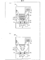
図6の(a)は、本実施の形態4の粉末乳調乳装置1DにおけるミルクMの混合状態を示す断面図であり、(b)は、比較例である粉末乳調乳装置200におけるミルクMの混合状態を示す断面図である。   6A is a cross-sectional view showing a mixed state of milk M in the powdered milk preparation device 1D of the fourth embodiment, and FIG. 6B is milk in the powdered milk preparation device 200 as a comparative example. It is sectional drawing which shows the mixed state of M.

図6の(a)に示すように、粉末乳調乳装置1Dは、蓋部8c(架設部)を備えている点において粉末乳調乳装置1A〜1Cと異なっている。蓋部8cは、調乳用ポット4の底部に向かって突出する突出部86(規制部材)を備えている。   As shown in FIG. 6 (a), the powdered milk preparation device 1D is different from the powdered milk preparation devices 1A to 1C in that a lid portion 8c (an erection part) is provided. The lid portion 8 c includes a protruding portion 86 (regulating member) that protrudes toward the bottom of the milk preparation pot 4.

突出部86は、実施の形態3における突出部84が有する凹部85と同様の機能を有する凹部87(当接部)を有している。この突出部86は、凹部87が形成されている先端から裾野にかけて広がる形状を有している点において突出部84と異なっている。なお、突出部86は、蓋部の中央部から突出し、先端部に向かうにつれて細くなっている形状を有していると言うこともできる。   The protrusion 86 has a recess 87 (contact portion) having the same function as the recess 85 of the protrusion 84 in the third embodiment. This protrusion 86 is different from the protrusion 84 in that it has a shape that widens from the tip where the recess 87 is formed to the base. In addition, it can be said that the protrusion part 86 has a shape which protrudes from the center part of a cover part and becomes thin as it goes to a front-end | tip part.

図6の(b)に示すように、比較例の粉末乳調乳装置200は、本実施の形態4の粉末乳調乳装置1Dに比べて、蓋部8cにおける突出部86と、撹拌子4cの突起部43とが省略されている点が異なり、その他の構成は同様である。   As shown in FIG. 6 (b), the powdered milk preparation device 200 of the comparative example is different from the powdered milk preparation device 1D of the fourth embodiment in that the protrusion 86 and the stirrer 4c in the lid portion 8c. The protrusion 43 is omitted, and the other configurations are the same.

図6の(a)・(b)を比較すると、本実施形態4の突出部86が上述の形状を有していることにより、混合物撹拌中(冷却時)において、ファン32から送風された風の流路が限定される。さらに、突出部86の側面は、テーパー状であり、ミルクMの撹拌時における擂鉢状の液面に沿った形状である。従って、ファン32(外部)から送風された風は、突出部86の外側表面(側面)とミルクMの液面との間の空間を通るため、比較例に比べて、上記風がミルクMの液面と接触する確率が高まる。そのため、ファン32による混合物(ミルクM)の冷却能力が向上する。この効果は、上述の実施の形態1〜3の粉末乳調乳装置1A〜1Cと比較した場合にも顕著である。   6A and 6B are compared, the protrusion 86 of the fourth embodiment has the above-described shape, so that the air blown from the fan 32 during the stirring of the mixture (during cooling). The flow path is limited. Furthermore, the side surface of the protrusion 86 is tapered, and has a shape along the bowl-shaped liquid surface when the milk M is stirred. Therefore, since the wind blown from the fan 32 (external) passes through the space between the outer surface (side surface) of the protrusion 86 and the liquid level of the milk M, the wind is higher than that of the comparative example. The probability of contact with the liquid level increases. Therefore, the cooling capacity of the mixture (milk M) by the fan 32 is improved. This effect is also remarkable when compared with the powdered milk preparation devices 1A to 1C of the above-described first to third embodiments.

また、本実施の形態4においても、実施の形態1〜3と同様の効果を得ることができる。   Also in the fourth embodiment, the same effects as in the first to third embodiments can be obtained.

〔確認実験結果〕
本発明の粉末乳調乳装置にて生成するミルクMの冷却速度について、確認実験を行った結果を以下に説明する。
[Results of confirmation experiment]
The result of having conducted the confirmation experiment about the cooling rate of the milk M produced | generated with the powdered milk preparation apparatus of this invention is demonstrated below.

本確認実験では、図6の(b)が示す比較例の粉末乳調乳装置200と、図1の(a)が示す実施の形態1、図5の(4)が示す実施の形態3、および図6の(a)が示す実施の形態4の粉末乳調乳装置1A・1C・1Dとを用いた。なお、図6の(b)と、図1の(a)・図5の(4)とを比較すれば理解できるように、粉末乳調乳装置200は、実施の形態4の粉末乳調乳装置1Dの比較例に該当すると共に、実施の形態1・3の粉末乳調乳装置1A・1Cの比較例にも該当する。   In this confirmation experiment, the powdered milk preparation apparatus 200 of the comparative example shown in (b) of FIG. 6, the first embodiment shown in (a) of FIG. 1, the third embodiment shown in (4) of FIG. And the powdered milk preparation apparatuses 1A, 1C, and 1D of Embodiment 4 shown in FIG. 6 (a) were used. As can be understood by comparing FIG. 6 (b) with FIG. 1 (a) and FIG. 5 (4), the powdered milk preparation device 200 is the powdered milk preparation of the fourth embodiment. This corresponds to the comparative example of the apparatus 1D and also corresponds to the comparative example of the powdered milk preparation apparatuses 1A and 1C of the first and third embodiments.

制御部7は、給湯開始と共に撹拌子4a・4cの回転を開始し、撹拌子回転数を500rpmに制御して、ミルクMを撹拌し続けた。このときの実験条件は、室温25℃、供給水温25℃、供給水量240cmとし、粉ミルクMP33gを調乳用ポット4内にセットした後、ヒーター12に900Wの電力をかけ、給湯速度160cm/minにて調乳用ポット4内に湯を供給しつつ、粉ミルクMPと湯とを混合することにより、調乳を行った。 The control unit 7 started the rotation of the stirring bars 4a and 4c simultaneously with the start of hot water supply, and controlled the rotation speed of the stirring bar to 500 rpm to continue stirring the milk M. The experimental conditions at this time were: room temperature 25 ° C., supply water temperature 25 ° C., supply water amount 240 cm 3 , powder milk MP33 g was set in the preparation pot 4, 900 W power was applied to the heater 12, and the hot water supply speed 160 cm 3 / Milk was prepared by mixing the powdered milk MP and hot water while supplying hot water into the milk preparation pot 4 at min.

図7は、上記各粉末乳調乳装置1A・1C・1D・200におけるミルクMの温度と給湯開始時点からの経過時間との関係を示すグラフである。図7に示すように、実施の形態4が、比較例、実施の形態1・3に比べ、ミルクMの冷却速度が速いことが確認できた。   FIG. 7 is a graph showing the relationship between the temperature of milk M and the elapsed time from the hot water supply start time in each of the powdered milk preparation devices 1A, 1C, 1D, and 200. As shown in FIG. 7, it was confirmed that the cooling rate of the milk M was faster in the fourth embodiment than in the comparative example and the first and third embodiments.

図7の結果から、図6の(a)が示す実施の形態4の粉末乳調乳装置1Dでは、混合物生成中(冷却時)において、ファン32から送風された風と混合物との接触効率を、他の実施の形態に比べて向上できるため、冷却能力が向上できることが確認された。   From the result of FIG. 7, in the powdered milk preparation device 1 </ b> D of Embodiment 4 shown in FIG. 6A, the contact efficiency between the air blown from the fan 32 and the mixture during the generation of the mixture (during cooling). Since it can be improved as compared with other embodiments, it has been confirmed that the cooling capacity can be improved.

また、比較例と比べて、実施の形態1・3においても、冷却能力が顕著に向上していることが確認された。そのため、比較例に比べて、実施の形態2においても、冷却能力が顕著に向上していると考えられる。   Further, it was confirmed that the cooling capacity was significantly improved in the first and third embodiments as compared with the comparative example. Therefore, it is considered that the cooling capacity is significantly improved in the second embodiment as compared with the comparative example.

したがって、実施の形態1〜4の粉末乳調乳装置1A〜1Dを使用することによって、上述の「乳児用乾燥粉末乳の安全な調乳、保存および取扱いに関するガイドライン」に順守した上で、ミルクMを生成し、かつ調乳から任意温度までの冷却を素早く自動で行うことができることが確認された。   Therefore, by using the powdered milk preparation devices 1A to 1D according to the first to fourth embodiments, the milk is prepared in compliance with the above-mentioned “Guidelines for Safe Formulation, Storage and Handling of Dry Powdered Milk for Infants”. It was confirmed that M can be generated and cooling from milk preparation to any temperature can be performed quickly and automatically.

〔まとめ〕
本発明の態様1に係る撹拌ユニット(粉末乳調乳装置1A〜1D)は、液体を受容する撹拌容器(調乳用ポット4)と、該撹拌容器の底部に配され、外部からの磁力により上記液体を撹拌する撹拌子(4a〜4c)とを備える撹拌ユニットであって、上記撹拌子が上記底部から上方に移動することを規制する規制部材(蓋部8a〜8c、突出部81・84・86)を備えており、該規制部材は、上記撹拌子が上記底部に配されている状態において、上記撹拌子の上方に位置し、かつ、上記撹拌子と間隙を有するように、上記撹拌容器に設けられている構成である。
[Summary]
The stirring unit (powdered milk preparation devices 1A to 1D) according to the first aspect of the present invention is arranged in a stirring container (milking pot 4) for receiving a liquid, and a bottom portion of the stirring container, and receives magnetic force from the outside. A stirring unit including a stirrer (4a to 4c) that stirs the liquid, and a regulating member that restricts the stirrer from moving upward from the bottom part (lid portions 8a to 8c, projecting portions 81 and 84). 86), and the restricting member is located above the stirrer and has a gap with the stirrer in a state where the stirrer is arranged at the bottom. It is the structure provided in the container.

上記の構成によると、上記撹拌子は、上方に移動することが上記規制部材により規制されるので、上方に移動して脱調することを抑制できる。また、上記規制部材は、上記撹拌子と間隙を有するので、上記撹拌子と分離されている。従って、上記規制部材は、上記撹拌子を支持する構造が不要であるので、簡便な構造とすることができ、その結果、上記撹拌子は、上記撹拌容器に対する設置および除去、洗浄などの取扱いが容易となる。   According to said structure, since the said stirring element is controlled by the said limitation member to move upwards, it can suppress moving out and stepping out. Further, since the regulating member has a gap with the stirring bar, it is separated from the stirring bar. Therefore, since the structure which supports the said stirring element is unnecessary for the said control member, it can be made into a simple structure, As a result, the said stirring element can handle handling, such as installation, removal, and washing | cleaning with respect to the said stirring container. It becomes easy.

本発明の態様2に係る撹拌ユニットは、上記態様1において、上記規制部材は、上記撹拌容器の開口部(41)に着脱可能に取り付けられることが好ましい。この場合、上記規制部材の上記取扱いが容易となる。   In the stirring unit according to aspect 2 of the present invention, in the aspect 1, it is preferable that the restriction member is detachably attached to the opening (41) of the stirring container. In this case, the handling of the regulating member is facilitated.

ところで、上記液体の撹拌中、上記液体の液面は、上記撹拌子の回転中心を底面とする擂鉢状となる。そこで、本発明の態様3に係る撹拌ユニットは、上記態様2において、上記規制部材は、上記開口部に架設される架設部(蓋部8a〜8c)と、該架設部から上記撹拌子の回転中心に向けて突出する突出部(81・84・86)とを備えることが好ましい。この場合、上記突出部は、上記撹拌容器の開口部から上記撹拌子の回転中心に向けて突出する形状であるので、他の形状に比べて、上記撹拌中の液面と接触する可能性が低くなる。従って、上記突出部が上記液面と接触することにより、上記液体内に気泡が発生する可能性を抑えることができる。なお、上記突出部は、1本でもよいし、複数本でもよい。   By the way, during the stirring of the liquid, the liquid surface of the liquid has a bowl shape with the rotation center of the stirring bar as the bottom surface. Therefore, the stirring unit according to aspect 3 of the present invention is the above-described aspect 2, wherein the restriction member includes an installation part (lid parts 8a to 8c) installed in the opening, and rotation of the stirring bar from the installation part. It is preferable to provide a protruding portion (81, 84, 86) protruding toward the center. In this case, since the protruding portion has a shape protruding from the opening of the stirring vessel toward the rotation center of the stirring bar, there is a possibility that the protruding portion may come into contact with the liquid level during stirring compared to other shapes. Lower. Therefore, the possibility that bubbles are generated in the liquid can be suppressed by the protrusion coming into contact with the liquid surface. In addition, the said protrusion part may be one and multiple may be sufficient as it.

ところで、上記突出部は、先端部にて上記撹拌中の液面と接触する可能性が高い。そこで、本発明の態様4に係る撹拌ユニットは、上記態様3において、上記突出部は、先端部が細くなっていてもよい。この場合、上記撹拌中の液面と接触する可能性をさらに低くすることができ、上記液体内に気泡が発生する可能性をさらに抑えることができる。   By the way, the protrusion is highly likely to come into contact with the liquid surface being stirred at the tip. Then, the stirring unit which concerns on aspect 4 of this invention WHEREIN: The said protrusion part may have the front-end | tip part thin in the said aspect 3. As shown in FIG. In this case, the possibility of contact with the liquid surface being stirred can be further reduced, and the possibility of bubbles being generated in the liquid can be further suppressed.

本発明の態様5に係る撹拌ユニットは、上記態様3において、上記突出部は、上記架設部の中央部から突出し、先端部に向かうにつれて細くなっていてもよい。この場合、上記突出部の側面は、テーパー状であり、上記液体の撹拌時における擂鉢状の液面に沿った形状である。従って、外部から上記撹拌容器に送風することにより撹拌中の上記液体を冷却する場合、上記送風された風は、上記突出部の側面と上記液面との間の空間を通るため、上記液面と接触する確率が向上し、その結果、上記液体の冷却能力を向上することができる。   In the stirring unit according to aspect 5 of the present invention, in the aspect 3, the protruding part may protrude from the center part of the erection part and become narrower toward the tip part. In this case, the side surface of the projecting portion is tapered, and has a shape along the bowl-shaped liquid surface when the liquid is stirred. Therefore, when the liquid being stirred is cooled by blowing air to the stirring container from the outside, the blown air passes through the space between the side surface of the projecting portion and the liquid level, so the liquid level The probability of contact with the liquid is improved, and as a result, the cooling capacity of the liquid can be improved.

本発明の態様6に係る撹拌ユニットは、上記態様1〜5において、上記撹拌子は、回転中心から上方に向けて突出する突起部(42・43)を備えていてもよい。この場合、上記突起部は把手になるため、ユーザーが上記撹拌子を上記撹拌容器内にセットしたり、上記撹拌容器から取り出したりすることが容易である。   In the stirring unit according to aspect 6 of the present invention, in the above aspects 1 to 5, the stirring bar may include a protrusion (42, 43) protruding upward from the center of rotation. In this case, since the protrusion becomes a handle, it is easy for the user to set the stirring bar in the stirring container or to remove it from the stirring container.

本発明の態様7に係る撹拌ユニットは、上記態様6において、上記規制部材は、上記突起部と当接することにより上記撹拌子の移動を規制する当接部(凹部85・87)を備え、上記当接部は、上記突起部と適合する形状を有していてもよい。上記適合する形状の例としては、上記当接部および上記突起部の一方が凸形状であり他方が凹形状である場合、上記当接部が上記突起部の先端部を囲む形状である場合、などが挙げられる。上記の構成によると、上記撹拌子の上方以外の方向への移動を規制することができ、上記撹拌子が脱調することをさらに抑制することができる。   The stirring unit according to Aspect 7 of the present invention is the stirring unit according to Aspect 6, wherein the restriction member includes a contact portion (recessed portions 85 and 87) that restricts the movement of the stirrer by contacting the protrusion. The abutting portion may have a shape that matches the protruding portion. As an example of the suitable shape, when one of the contact portion and the protrusion is a convex shape and the other is a concave shape, the contact portion is a shape surrounding the tip of the protrusion, Etc. According to said structure, the movement to directions other than the upper direction of the said stirring element can be controlled, and it can further suppress that the said stirring element steps out.

本発明の態様8に係る撹拌ユニットは、上記態様6または7において、上記突起部の先端部(44)は、許容量以下の液体が上記撹拌容器に貯留されている状態において、上記液体の液面から露出していてもよい。この場合、上記先端部を把手として、上記撹拌子を上記撹拌容器にセットすると、ユーザーの手から上記先端部に付着した付着物が、上記液体に混合する可能性を軽減できるため、衛生的にさらに好ましい状態で上記液体の撹拌が可能である。   In the stirring unit according to aspect 8 of the present invention, in the above-described aspect 6 or 7, the tip portion (44) of the protruding portion is a liquid liquid in a state where an allowable amount or less of liquid is stored in the stirring container. It may be exposed from the surface. In this case, if the tip is used as a handle and the stirring bar is set in the stirring container, the possibility that adhering matter adhering to the tip from the user's hand can be mixed with the liquid can be reduced. Furthermore, the liquid can be stirred in a preferable state.

本発明は上述した各実施形態に限定されるものではなく、請求項に示した範囲で種々の変更が可能であり、異なる実施形態にそれぞれ開示された技術的手段を適宜組み合わせて得られる実施形態についても本発明の技術的範囲に含まれる。さらに、各実施形態にそれぞれ開示された技術的手段を組み合わせることにより、新しい技術的特徴を形成することができる。   The present invention is not limited to the above-described embodiments, and various modifications are possible within the scope shown in the claims, and embodiments obtained by appropriately combining technical means disclosed in different embodiments. Is also included in the technical scope of the present invention. Furthermore, a new technical feature can be formed by combining the technical means disclosed in each embodiment.

本発明は、適切な調乳方法を順守して自動調乳することができる粉末乳調乳装置又はコーヒーやお茶等の液体抽出装置等の混合物生成装置に適用できる。   INDUSTRIAL APPLICABILITY The present invention can be applied to a powdered milk preparation device that can automatically adjust the milk while complying with an appropriate milk preparation method, or a mixture generation device such as a liquid extraction device such as coffee or tea.

1A、1B、1C、1D 粉末乳調乳装置(撹拌ユニット)
4 調乳用ポット(撹拌容器)
4a、4b、4c 撹拌子
5 モーター
8a、8b、8c 蓋部(架設部)
40 磁石
41 開口部
42、43 突起部
44 先端部(突起部)
81、84、86 突出部(規制部材)
85、87 凹部(当接部)
1A, 1B, 1C, 1D Powdered milk preparation device (stirring unit)
4 Milking pot (stirring container)
4a, 4b, 4c Stirrer 5 Motor 8a, 8b, 8c Lid (erection part)
40 Magnet 41 Opening 42, 43 Protrusion 44 Tip (Protrusion)
81, 84, 86 Protruding part (regulating member)
85, 87 Concave part (contact part)

Claims (8)

液体を受容する撹拌容器と、該撹拌容器の底部に配され、外部からの磁力により上記液体を撹拌する撹拌子とを備える撹拌ユニットであって、
上記撹拌子が上記底部から上方に移動することを規制する規制部材を備えており、
該規制部材は、上記撹拌子が上記底部に配されている状態において、上記撹拌子の上方に位置し、かつ、上記撹拌子と間隙を有するように、上記撹拌容器に設けられていることを特徴とする撹拌ユニット。
A stirring unit comprising a stirring container for receiving a liquid, and a stirring bar arranged at the bottom of the stirring container and stirring the liquid by an external magnetic force,
A regulating member that regulates movement of the stirrer upward from the bottom,
The regulating member is provided in the stirring vessel so as to be positioned above the stirring bar and to have a gap with the stirring bar in a state where the stirring bar is arranged at the bottom. Stirring unit characterized.
上記規制部材は、上記撹拌容器の開口部に着脱可能に取り付けられることを特徴とする請求項1に記載の撹拌ユニット。   The stirring unit according to claim 1, wherein the regulating member is detachably attached to the opening of the stirring container. 上記規制部材は、上記開口部に架設される架設部と、該架設部から上記撹拌子の回転中心に向けて突出する突出部とを備えることを特徴とする請求項2に記載の撹拌ユニット。   The stirring unit according to claim 2, wherein the restricting member includes a erected part that is erected on the opening, and a protruding part that projects from the erected part toward the rotation center of the agitator. 上記突出部は、先端部が細くなっていることを特徴とする請求項3に記載の撹拌ユニット。   The stirring unit according to claim 3, wherein a tip of the protruding portion is thin. 上記突出部は、上記架設部の中央部から突出し、先端部に向かうにつれて細くなっていることを特徴とする請求項3に記載の撹拌ユニット。   The stirring unit according to claim 3, wherein the protruding portion protrudes from a central portion of the erection portion and becomes thinner toward the tip portion. 上記撹拌子は、回転中心から上方に向けて突出する突起部を備えていることを特徴とする請求項1から5までの何れか1項に記載の撹拌ユニット。   The stirring unit according to any one of claims 1 to 5, wherein the stirrer includes a protrusion protruding upward from the center of rotation. 上記規制部材は、上記突起部と当接することにより上記撹拌子の移動を規制する当接部を備え、
上記当接部は、上記突起部と適合する形状を有していることを特徴とする請求項6に記載の撹拌ユニット。
The regulating member includes an abutting portion that regulates movement of the stirring bar by abutting with the protruding portion,
The stirring unit according to claim 6, wherein the contact portion has a shape that matches the protrusion.
上記突起部の先端部は、許容量以下の液体が上記撹拌容器に貯留されている状態において、上記液体の液面から露出していることを特徴とする請求項6または7に記載の撹拌ユニット。   8. The stirring unit according to claim 6, wherein a tip portion of the protrusion is exposed from a liquid surface of the liquid in a state where a liquid having an allowable amount or less is stored in the stirring container. .
JP2016091830A 2016-04-28 2016-04-28 Stirring unit Pending JP2017196323A (en)

Priority Applications (1)

Application Number Priority Date Filing Date Title
JP2016091830A JP2017196323A (en) 2016-04-28 2016-04-28 Stirring unit

Applications Claiming Priority (1)

Application Number Priority Date Filing Date Title
JP2016091830A JP2017196323A (en) 2016-04-28 2016-04-28 Stirring unit

Publications (1)

Publication Number Publication Date
JP2017196323A true JP2017196323A (en) 2017-11-02

Family

ID=60236877

Family Applications (1)

Application Number Title Priority Date Filing Date
JP2016091830A Pending JP2017196323A (en) 2016-04-28 2016-04-28 Stirring unit

Country Status (1)

Country Link
JP (1) JP2017196323A (en)

Similar Documents

Publication Publication Date Title
CN101637356B (en) Automatic milk powder dissolving device
TWI225780B (en) Infant formula preparation apparatus
CN107613820B (en) Stirring piece and stirring device
JP2021517012A (en) Food processor thermal management
JP2021516565A (en) Handling of food processors
JP2021503993A (en) Adjusted heat generation for food processing
WO2016132887A1 (en) Mixture production apparatus
JP6006347B2 (en) Beverage production equipment
JP2015139594A (en) Cooled hot water generator, beverage generator, and powdered milk formula device
JP2021517016A (en) Controlled positioning within the food processor
JP6170503B2 (en) Baby bottle heater
JP2016131859A (en) Beverage producing apparatus
CN107847077B (en) Liquid cooling device and beverage producing device
KR100781324B1 (en) Water/Powdered Milk Mixing Device for Nursing
JP2017196323A (en) Stirring unit
JP2015157252A (en) Mixture producing apparatus
JP6042927B2 (en) Mixer generator
CN212213535U (en) Milk stirring device with disinfection function
JP6697505B2 (en) Mixer generator
JP6716332B2 (en) Liquid cooling device
JP6694487B2 (en) Liquid supply device
CN208925920U (en) Germ-free milk machine
EP3413764B1 (en) Method and machine for preparing infant milk formula
JP5805745B2 (en) Mixture generating apparatus and mixture generating method