JP2017196002A - Masticatory ability evaluation device - Google Patents
Masticatory ability evaluation device Download PDFInfo
- Publication number
- JP2017196002A JP2017196002A JP2016087626A JP2016087626A JP2017196002A JP 2017196002 A JP2017196002 A JP 2017196002A JP 2016087626 A JP2016087626 A JP 2016087626A JP 2016087626 A JP2016087626 A JP 2016087626A JP 2017196002 A JP2017196002 A JP 2017196002A
- Authority
- JP
- Japan
- Prior art keywords
- bite
- container
- distance information
- fragment
- ability evaluation
- Prior art date
- Legal status (The legal status is an assumption and is not a legal conclusion. Google has not performed a legal analysis and makes no representation as to the accuracy of the status listed.)
- Granted
Links
Images

Landscapes
- Dental Tools And Instruments Or Auxiliary Dental Instruments (AREA)
- Investigating Or Analysing Materials By Optical Means (AREA)
- Measurement Of The Respiration, Hearing Ability, Form, And Blood Characteristics Of Living Organisms (AREA)
Abstract
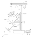
【課題】咬断片の大きさのばらつきを考慮して咀嚼能力を評価することができる咀嚼能力評価装置を提供する。【解決手段】咀嚼能力評価装置100は、被験者により咀嚼された試験食の咬断片2が載置される載置面11aを有する測定台10と、載置面11aから所定距離L0だけ離れた測定位置から、載置面11a上の咬断片2までの距離情報を取得する距離情報取得手段22と、距離情報取得手段22により取得された距離情報に基づき、咀嚼能力を評価するための評価値を導出する評価値導出手段30とを備える。【選択図】図1A masticatory ability evaluation apparatus capable of evaluating masticatory ability in consideration of variation in the size of a bite fragment is provided. A chewing ability evaluation apparatus 100 includes a measuring table 10 having a mounting surface 11a on which a bite piece 2 of a test meal chewed by a subject is mounted, and a measurement separated from the mounting surface 11a by a predetermined distance L0. Based on the distance information acquisition means 22 for acquiring the distance information from the position to the bite fragment 2 on the placement surface 11a and the distance information acquired by the distance information acquisition means 22, an evaluation value for evaluating the masticatory ability Evaluation value deriving means 30 for deriving. [Selection] Figure 1
Description
本発明は、咀嚼能力を評価する咀嚼能力評価装置に関する。 The present invention relates to a masticatory ability evaluation apparatus for evaluating masticatory ability.
従来より、咀嚼能力測定用の試験食を所定条件の下で被験者に咀嚼させ、咀嚼後の咬断片の状態に応じて咀嚼能力を評価する装置が知られている(例えば特許文献1参照)。特許文献1記載の装置では、咀嚼能力測定用試験食としてグミゼリーを用い、咀嚼後の咬断片の表面から水中に溶出するゼラチンあるいはグルコースの濃度を測定し、その濃度から被験者の咀嚼能力の評価値を導出する。
2. Description of the Related Art Conventionally, there has been known an apparatus that allows a subject to chew a test meal for measuring chewing ability under a predetermined condition and evaluates the chewing ability according to the state of the bite fragment after chewing (see, for example, Patent Document 1). In the apparatus described in
ところで、例えば被験者の口腔内の左右いずれかに麻痺が起こると、左右の咀嚼能力に差が生じ、咬断片の大きさにばらつきが生じる。したがって、被験者の咀嚼能力を精度よく評価するためには、咬断片の大きさのばらつきを考慮することが好ましい。しかしながら、上記特許文献1記載の装置のように、水中に溶出した物質の濃度を測定して咀嚼能力を評価する手法では、咬断片の大きさのばらつきを考慮することが困難である。
By the way, for example, when paralysis occurs on either the left or right side of the oral cavity of the subject, the left and right chewing abilities differ, and the size of the bite fragment varies. Therefore, in order to accurately evaluate the masticatory ability of the subject, it is preferable to consider variation in the size of the bite fragment. However, in the method of measuring the concentration of a substance eluted in water and evaluating the masticatory ability as in the device described in
本発明の一態様である咀嚼能力評価装置は、被験者により咀嚼された試験食の咬断片が載置される載置面を有する測定台と、載置面から所定距離だけ離れた測定位置から、載置面上の咬断片までの距離情報を取得する距離情報取得手段と、距離情報取得手段により取得された距離情報に基づき、咀嚼能力を評価するための評価値を導出する評価値導出手段と、を備えることを特徴とする。 The masticatory ability evaluation apparatus according to one aspect of the present invention includes a measurement table having a mounting surface on which a bite piece of a test meal chewed by a subject is mounted, and a measurement position separated from the mounting surface by a predetermined distance, Distance information acquiring means for acquiring distance information to the bite fragment on the mounting surface, and evaluation value deriving means for deriving an evaluation value for evaluating masticatory ability based on the distance information acquired by the distance information acquiring means; It is characterized by providing.
本発明によれば、咬断片の載置面から所定距離だけ離れた測定位置から載置面上の咬断片までの距離情報を取得し、この距離情報に基づき咀嚼能力を評価するための評価値を導出するので、咬断片の大きさのばらつきを考慮した咀嚼能力の評価が可能となる。 According to the present invention, the evaluation value for obtaining the distance information from the measurement position away from the mounting surface of the bite fragment by a predetermined distance to the bite fragment on the mounting surface and evaluating the masticatory ability based on this distance information Therefore, it is possible to evaluate the masticatory ability in consideration of the variation in the size of the bite fragment.
−第1の実施形態−
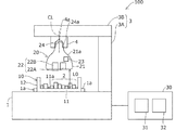
以下、図1〜図4Bを参照して本発明の第1の実施形態について説明する。図1は、本発明の第1の実施形態に係る咀嚼能力評価装置100の全体構成を概略的に示す図である。咀嚼能力評価装置100は、ベース1上に配置された容器10と、容器10の上方に設けられたセンサユニット20と、センサユニット20からの信号に基づき咀嚼能力を評価するコントローラ30とを有する。
-First embodiment-
Hereinafter, a first embodiment of the present invention will be described with reference to FIGS. FIG. 1 is a diagram schematically showing an overall configuration of a masticatory
容器10は、底壁11と底壁11の周縁部から立設する側壁12とを有し、上方が開口されている。ベース1の上面には位置決め部1aが設けられ、容器10は、位置決め部1aを介してベース1上の所定位置に位置決めした状態で搭載される。ベース1上に容器10が搭載された状態では、底壁11の上面11aは水平となり、この上面11aに、被験者により咀嚼された咀嚼能力測定用の試験食の咬断片2が載置される。試験食としては、被験者が咀嚼することで、口腔内で溶けずに細分化することが可能な所定形状でかつ所定の硬さを有する食品が用いられる。例えば立方体形状のグミゼリーが試験食として用いられる。
The
センサユニット20はアーム3により支持される。アーム3は、ベース1から立設された第1アーム3Aと、第1アーム3Aの上端からベース1の上方に向けて延設された第2アーム3Bとを有する。容器10の中心部上方における第2アーム3Bの下面には、雌ねじ部4aを有するソケット4が設けられる。センサユニット20は、筐体21と、筐体21内にそれぞれ配置されたセンサ部22および無線通信部23とを有する。
The
筐体21は、軸線CLを中心とした対称形状を呈する。より具体的には、筐体21は、軸線CLからその外周面までの距離が下方にかけて拡大する拡径部21aを有し、全体が略電球形状を呈する。筐体21の上端部には、口金24が設けられる。口金24は、ソケット4の雌ねじ部4aに対応した雄ねじ部24aを有し、雄ねじ部24aを介してソケット4の雌ねじ部4aに螺合される。これによりセンサユニット20がアーム3の所定位置に保持されるとともに、口金24を介してセンサ部22と無線通信部23とに電力を供給できる。
The
センサ部22は、咬断片2が搭載される容器10の上面11aに対向して、かつ、上面11aから所定距離L0だけ離れて配置された距離センサにより構成される。距離センサとしては、例えば咬断片2に向けて赤外線を照射し、その反射光を受光することで咬断片2までの距離を検出する赤外線距離センサが用いられ、センサ部22は、赤外線の投光部22Aと受光部22Bとを有する。受光部22Bは、所定帯域の赤外線が透過するレンズ部を有する赤外線カメラにより構成される。センサ部22からの信号は無線通信部23を介してコントローラ30に送信される。
The
コントローラ30は、CPU,ROM,RAM、その他の周辺回路などを有する演算処理装置を含んで構成されるコンピュータを含み、センサ部22からの信号に基づき、咀嚼能力を評価するための評価値(咀嚼評価値)を導出する。コントローラ30には、センサ部22から容器10の上面11aまでの所定距離L0が予め記憶されている。コントローラ30は、各種指令や設定値等を入力する入力部31と、咀嚼評価値を出力する出力部32とを有する。入力部31と出力部32とは、例えばタッチパネルにより一体に構成することができる。
The
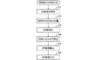
次に、本実施形態に係る咀嚼能力評価装置100を用いた咀嚼能力評価方法について説明する。図2は、本発明の第1の実施形態に係る咀嚼能力評価方法の手順を示すフローチャートである。
Next, a masticatory ability evaluation method using the masticatory
まず、所定条件の下で、被験者に試験食(グミゼリー)を咀嚼させる(ステップS1)。例えば、所定回数だけあるいは所定時間だけ試験食を咀嚼させる。次に、被験者の口腔内から咀嚼後の全ての咬断片2を取り出し、水道水等により洗浄した後、咬断片2を容器10内に配置する(ステップS2)。このとき、咬断片2が互いに重ならないように容器10の上面11aに咬断片2を載置し、その後、位置決め部1aを介して容器10をベース1上の所定位置に搭載する。
First, a test meal (gummy jelly) is chewed by a subject under predetermined conditions (step S1). For example, the test meal is chewed only a predetermined number of times or for a predetermined time. Next, after all the
なお、ベース1に振動装置を設け、振動装置により容器10を振動させることで、咬断片2の重なりを防ぐようにしてもよい。この場合、振動装置をコントローラ30に接続し、入力部31により振動装置の駆動を指令するようにしてもよい。
The
次いで、センサ部22から咬断片2までの距離(鉛直方向距離)L1を測定する(ステップS3)。この距離測定は、例えば入力部31の操作により距離測定の開始が指令され、コントローラ30からセンサ部22に動作開始指令が出力されることで行われる。これにより、投光部22Aから咬断片2に向けて赤外線が照射されるとともに、咬断片2上の各測定点で反射した赤外線が受光部22Bで受光される。センサ部22が取得した信号はコントローラ30に送信される。
Next, a distance (vertical direction distance) L1 from the
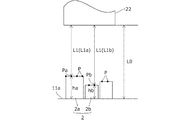
図3は、咬断片2上の測定点Pの一例を示す図である。測定点Pは、容器10の水平方向全域にわたり、咬断片2上に所定間隔毎に設定される。コントローラ30は、センサ部22からの信号を用いて、センサ部22から咬断片2上の各測定点Pまでの距離L1を算出する。これにより咬断片2の測定点P毎の複数の距離データが得られる。なお、咬断片2の大きさが大きいほど水平方向における咬断片2の面積が大きくなり、したがって、同一の咬断片2に設定される測定点Pの個数が多くなる。
FIG. 3 is a diagram illustrating an example of the measurement point P on the
センサ部22から各測定点Pまでの距離L1は測定点Pにおける咬断片2の大きさ(高さ)に応じて変化する。例えば図3に示すように、大きさの異なる咬断片2a,2bが存在する場合に、咬断片2a上の測定点Paまでの距離L1aは、咬断片2b上の測定点Pbまでの距離L1bよりも短い。なお、容器10の上面11aに咬断片2が存在しない場合には、容器10の上面11aに測定点Pが設定され、測定距離L1は所定距離L0となる。
The distance L1 from the
次に、コントローラ30は、所定距離L0から各測定点Pの測定距離L1を減算し、各測定点Pにおける咬断片2の大きさh(高さ)を算出する(ステップS4)。例えば図3に示すように、測定点Paにおける咬断片2aの大きさha、および測定点Pbにおける咬断片2bの大きさhbをそれぞれ算出する。
Next, the
次に、コントローラ30は、算出した咬断片2の大きさhに対応する測定点Pの割合、すなわち、咬断片2の大きさhに対応する測定点Pの個数Nを、咀嚼能力を評価するための評価値A1として算出する(ステップS5)。これにより同一の大きさhの咬断片2が容器10内にどの程度存在するか、換言すると、咬断片2の大きさhの分布を、評価値A1を用いて把握できる。次いで、コントローラ30は、算出した評価値A1を出力部32に出力する(ステップS6)。
Next, the
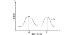
図4A,図4Bは、それぞれ出力部32に表示される評価値A1の一例を示す図である。図では、横軸が咬断片2の大きさhを、縦軸が咬断片2の大きさhに対応する測定点Pの個数N、すなわち評価値A1をそれぞれ示す。図中の特性f1,f2,f3は、それぞれ異なる被験者による咀嚼結果から得られた特性である。
4A and 4B are diagrams illustrating an example of the evaluation value A1 displayed on the
図4Aに示すように、特性f1と特性f2とを比較すると、特性f1は、大きさh1において評価値A1が最大となる。すなわち、大きさh1に、測定点Pの個数Nのピーク値が存在し、測定点Pの個数Nが最も多くなる。これに対し、特性f2は、大きさh2において評価値A1が最大となる。評価値A1が最大となる大きさh1,h2は、容器10内に最も多く存在する咬断片2の大きさh(高さ)を意味し、以降、これを代表大きさと呼ぶこともある。図4Aでは、特性f2の代表大きさh2は、特性f1の代表大きさh1よりも小さい。代表大きさが小さいほど、試験食が細かく咀嚼されることとなるため、咀嚼能力が高いと評価できる。
As shown in FIG. 4A, when the characteristic f1 and the characteristic f2 are compared, the evaluation value A1 of the characteristic f1 becomes the maximum at the magnitude h1. That is, the peak value of the number N of measurement points P exists in the size h1, and the number N of measurement points P is the largest. On the other hand, the characteristic f2 has the maximum evaluation value A1 at the magnitude h2. The sizes h1 and h2 at which the evaluation value A1 is the maximum mean the size h (height) of the
一方、例えば被験者の口腔内の左右いずれかに麻痺が起こると、左右の咀嚼能力に差が生じ、咬断片2の大きさhにばらつきが生じる。すなわち、麻痺が起こっていない側での咬断片2は小さく、麻痺が起こっている側での咬断片2は大きくなる。このため、例えば図4Bの特性f3に示すように、評価値A1のピーク値が2箇所で発生し、2つの代表大きさh3,h4が得られる。したがって、評価値A1の特性に複数のピーク値が存在するか否かを判定することにより、被験者の口腔内に麻痺が起きているか否かを判断することが可能となる。
On the other hand, for example, when paralysis occurs on either the left or right side of the subject's mouth, the left and right chewing ability is different, and the size h of the
第1の実施形態によれば以下のような作用効果を奏することができる。
(1)第1の実施形態に係る咀嚼能力評価装置100は、被験者により咀嚼された試験食の咬断片2が載置される上面11aを有する容器10と、上面11aから所定距離L0だけ離れた測定位置から、上面11a上の咬断片2までの距離情報を取得するセンサ部22と、センサ部22により取得された距離情報に基づき、咀嚼能力を評価するための評価値A1を導出するコントローラ30とを備える。
According to 1st Embodiment, there can exist the following effects.
(1) The chewing
このようにセンサ部22により咬断片2までの距離情報を取得することで、容器10全域における咬断片2の大きさを把握することができ、咬断片2の大きさのばらつきを考慮した咀嚼能力の評価が可能となる。その結果、口腔内の左右いずれかに麻痺が生じているか否かなどの判定が可能となる。また、本実施形態のように、咬断片2までの距離情報によって咀嚼能力を評価する手法を採用すると、咀嚼後の咬断片2を水中に溶出させる必要がないため、特殊な試験食を準備する必要がなく、咀嚼能力を安価に評価することができる。咀嚼後の咬断片2を乾燥させる必要もないため、咀嚼能力の評価を迅速に実施することも可能である。
Thus, by acquiring the distance information to the
(2)センサ部22は、容器10の上面11aに対向して配置された距離センサとして投光部22Aと受光部22Bとを有する。したがって、センサ部22から咬断片2の上面までの距離情報を取得することができ、咬断片2の大きさ(高さ)を容易に把握できる。
(2) The
(3)コントローラ30は、センサ部22により取得された距離情報に対応する咬断片2の分布を評価値A1として導出する。これにより評価値A1がピークとなる咬断片2の大きさh(代表大きさ)、すなわち最も個数の多い咬断片2の大きさhを求めることができ、咀嚼能力の評価にとって有用な情報が得られる。
(3) The
−第2の実施形態−
図5,6を参照して本発明の第2の実施形態について説明する。以下では第1の実施形態との相違点を主に説明する。第1の実施形態では単一の容器10に咬断片2を配置したが、第2の実施形態では、咬断片2の大きさに応じて咬断片2を複数のグループに分離し、咬断片2をグループ毎に異なる容器10に配置する。さらに、第2の実施形態では、容器10に対してセンサユニット20を相対移動可能に設ける。
-Second Embodiment-
A second embodiment of the present invention will be described with reference to FIGS. Hereinafter, differences from the first embodiment will be mainly described. In the first embodiment, the
図5は、本発明の第2の実施形態に係る咀嚼能力評価装置100Aの全体構成を概略的に示す図である。なお、図1と同一の箇所には同一の符号を付す。以下では、図示のように直交3軸方向をX方向、Y方向、およびZ方向と定義する。なお、Z方向は、第1アーム3Aの延在する方向、すなわち重力方向(上下方向)であり、X方向は、第2アーム3Bの延在する方向である。
FIG. 5 is a diagram schematically showing an overall configuration of a masticatory
図5に示すように、咀嚼能力評価装置100Aは、複数(図では3個)の容器10を有する。これら容器10を、上から順に第1容器101、第2容器102、第3容器103と称する。第1アーム3Aにはステイ支持部104が設けられ、ステイ支持部104にステイ105が取り付けられる。ステイ105は、先端部に第1容器101〜第3容器103の容器支持部105aを有し、各容器支持部105aにそれぞれ第1容器101〜第3容器103が支持される。第1容器101〜第3容器103は、容器101〜103の上方空間が開放されるようにそのX方向位置が互いにずれている。なお、各容器101〜103のY方向位置は互いに一致している。
As shown in FIG. 5, the masticatory
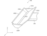
図6は、第2容器102の斜視図である。図6に示すように、第2容器102はXZ断面において略V字形状に配置された略矩形状の一対の底板1021,1022と、Y方向端部の開口を塞ぐ一対の側板1023,1024とを有する。一対の底板1021,1022の底部はX方向に互いに所定幅ΔX2だけ隔てられ、第2容器102の底部には、X方向の幅ΔXで、Z方向に貫通する開口部102aがY方向に沿って形成される。
FIG. 6 is a perspective view of the
図5に示すように、第1容器101は第2容器102と同様、断面略V字状に形成される。但し、第1容器101のX方向の開口部101aの幅ΔX1は、第2容器102の開口部102aの幅ΔX2よりも大きい。第3容器103も断面略V字状に形成されるが、第3容器103の底部には開口部は設けられない。これにより所定幅ΔX1よりも小さな咬断片2は、第1容器101の開口部101aを介して落下し、所定幅ΔX2よりも小さな咬断片2は、第2容器102の開口部102aを介して落下する。
As shown in FIG. 5, the
第2の実施形態では、各容器101〜103の底部、特に第1容器101,第2容器102においては開口部101a,102aよりも上方に、咬断片2が載置される面、すなわち容器101〜103の上面11a(点線)が形成される。第1容器101,第2容器102にそれぞれ開口部101a,102aを設けたことにより、第1容器101の上面11aには所定幅ΔX1以上の大型の咬断片2aが載置され、第2容器102の上面11aには所定幅ΔX2以上かつ所定幅ΔX1未満の中型の咬断片2bが載置され、第3容器103の上面11aには所定幅ΔX2未満の小型の咬断片2cが載置される。これにより咬断片2をその大きさに応じて3つのグループに分離し、それぞれを互いに異なる容器101〜103に配置できる。
In 2nd Embodiment, in the bottom part of each container 101-103, especially in the
第1アーム3Aのステイ支持部104には加振装置106が設けられ、加振装置106により、ステイ105を介して各容器101〜103を加振することができる。これにより各容器101〜103内の咬断片2の重なりを防ぐことができ、各容器101〜103の底部に沿って咬断片2をY方向に一列に並んで配置することができる。
The
第2の実施形態では、センサユニット20(センサ部22)が移動機構を介して容器10に対し相対移動可能に設けられる。具体的には、第2アーム3Bは、駆動機構110により第1アーム3Aに対しX方向に移動可能に設けられる。第2アーム3Bの先端部には、Z方向に延在する第3アーム3Cが設けられ、第3アーム3Cの下端部にソケット4が固定される。第3アーム3Cは、駆動機構120により第2アーム3Bに対しZ方向に移動可能に設けられる。これによりセンサ部22を、第1容器101の上面11aから所定距離L0上方である第1位置PS1、第2容器102の上面11aから所定距離L0上方である第2位置PS2、および第3容器103の上面11aから所定距離L0上方である第3位置PS3にそれぞれ移動することができる。
In 2nd Embodiment, the sensor unit 20 (sensor part 22) is provided so that relative movement with respect to the
なお、駆動機構110,120は、例えば電動モータと、電動モータの回転運動をアーム3B,3Cの直進運動に変換するボールねじなどの動力変換機構とにより構成することができる。図示は省略するが、咀嚼能力評価装置100Aは、センサ部22のX方向およびZ方向の位置を検出するセンサを有し、コントローラ30は、センサからの信号に応じて駆動機構(電動モータ)の動作を制御する。
The
第2の実施形態において、被験者の咀嚼能力を評価する際には、咀嚼後の咬断片2を第1容器101に投入するとともに、加振装置106により容器101〜103を加振する。容器101〜103が加振されると、小型および中型の咬断片2b,2cが第1容器101から第2容器102に振るい落とされ、さらに小型の咬断片2cが第2容器102から第3容器103に振るい落とされる。これにより咬断片2の大きさに応じて咬断片2が各容器101〜103に分離され、各容器101〜103の底部に一列に並んで配置される。
In the second embodiment, when evaluating the chewing ability of the subject, the
この状態から、コントローラ30が駆動機構110,120に制御信号を出力することにより、センサ部22を第1位置PS1、第2位置PS2、および第3位置PS3に順次移動する。そして、コントローラ30からの指令により、各位置PS1〜PS3でセンサ部22を動作させ、センサ部22から咬断片2までの距離を測定するとともに、測定結果をコントローラ30に送信する。この場合、各容器101〜103には、ほぼ同一の大きさの咬断片2が一列に並んで配置されるため、センサ部22により咬断片2までの距離を精度よく測定することができる。コントローラ30は、センサ部22からの信号に基づいて第1の実施形態と同様に、咬断片の大きさhの分布(評価値A1)を算出し、出力部32に出力する。
From this state, when the
このように第2の実施形態では、咬断片2の大きさに応じて咬断片2を複数のグループに分離するために、開口部101a,102aの大きさの異なる複数の容器101〜103を備え、分離された各グループの咬断片2a〜2cがそれぞれ容器101〜103の上面11aに載置される。これにより例えば小型の咬断片2cが大型の咬断片2aの影に隠れてセンサ部22で認識されなくなることを防止し、各々の咬断片2上に確実に測定点Pを設定できる。よって、全ての咬断片2に対し距離測定を行うことができ、評価値A1を精度よく算出することができる。
Thus, in 2nd Embodiment, in order to isolate | separate the
複数の容器101〜103は、各容器101〜103の上面11aの上方空間が開放されるように互いに水平方向の位置をずらして配置される。これにより、単一のセンサ部22を、移動機構を介して第1位置PS1、第2位置PS2および第3位置PS3へと順次移動させることで、各容器101〜103内の咬断片2の大きさを測定することができる。したがって、センサ部22の個数を増加させる必要がなく、安価に構成することができる。
The plurality of
容器101〜103が下方にかけてすぼめられ、断面略V字形状を呈するようにしたので、各容器101〜103内に咬断片2が一列に並んで配置される。したがって、センサ部22による距離測定の範囲を狭い範囲に抑えることができる。よって、第2の実施形態のように複数の容器10のZ方向およびX方向の位置をずらして配置する場合においてセンサ部22の移動範囲が抑えられ、装置全体の大型化を防ぐことができる。
Since the
(変形例)
上記実施形態は種々の形態に変形することができる。例えば、上記第2の実施形態では、移動機構を介して、容器101〜103に対してセンサ部22を移動させるようにしたが、センサ部22に対して容器101〜103を移動させるようにしてもよい。あるいはセンサ部22と容器101〜103の両方を移動させるようにしてもよい。駆動機構110,120により、センサ部22を容器10に対してX方向(水平方向)およびZ方向(鉛直方向)に相対移動させるようにしたが、斜め方向に移動させるようにしてもよく、移動機構の構成は上述したものに限らない。
(Modification)
The above embodiment can be modified into various forms. For example, in the second embodiment, the
上記第2の実施形態では、所定幅ΔX1の開口部101aを有する第1容器101と、所定幅ΔX2(<ΔX1)の開口部102aを有する第2容器102と、開口部を有しない第3容器103とを、上下方向に一部が重なるように配置し、第1容器101に咬断片2を投入することにより、咬断片2の大きさに応じて咬断片2を複数のグループに分離するようにしたが、分離手段の構成はこれに限らない。各容器101〜103の上面11a(載置面)の上方空間が開放されるように互いに水平方向の位置をずらして容器101〜103を配置したが、各容器101〜103内の咬断片2のセンサ部22による距離測定が可能であれば、容器101〜103の配置はこれに限らない。容器10の個数も上述したものに限定されない。
In the second embodiment, the
上記第1の実施形態では、被験者により咀嚼された試験食の咬断片2が載置される載置面(上面11a)を有する測定台として、底壁11と側壁12とを有する容器10を用い、第2の実施形態では、下方にかけてすぼめられた断面略V字形状の容器を用いたが、測定台の構成は上述したものに限らない。上記実施形態では、センサ部22として赤外線カメラ(受光部22B)を用いが、載置面から所定距離L0だけ離れた測定位置から、載置面上の咬断片2までの距離情報を取得するのであれば、距離情報取得手段の構成はいかなるものもよい。載置面に対向して赤外線距離センサを配置したが、レーザー距離センサ等、他の距離センサを配置してもよい。センサ部22を有するセンサユニット20をソケット4に取り付けるようにしたが、センサ部22の取付部の構成はこれに限らない。センサ部22からの信号をコントローラ30に無線で送信するようにしたが、有線で送信してもよい。
In the said 1st Embodiment, the
上記実施形態では、コントローラ30が、センサ部22により取得された距離情報に対応する咬断片2の分布を評価値A1として導出したが、取得された距離情報に基づき咀嚼能力を評価するための評価値を導出するのであれば、評価値導出手段としてのコントローラ30の構成はいかなるものでもよい。センサ部22からの信号により個々の咬断片2の形状を特定し、これを評価値A1として用いてもよい。例えば距離測定値がL0となる測定点Pは容器10の上面11aにあるものとして、上面11aの複数の測定点Pによって囲まれた領域を単一の咬断片2であると判定し、咬断片2の形状を特定するようにしてもよい。
In the above embodiment, the
以上の説明はあくまで一例であり、本発明の特徴を損なわない限り、上述した実施形態および変形例により本発明が限定されるものではない。上記実施形態および変形例の構成要素には、発明の同一性を維持しつつ置換可能かつ置換自明なものが含まれる。すなわち、本発明の技術的思想の範囲内で考えられる他の形態についても、本発明の範囲内に含まれる。また、上記実施形態と変形例の1つまたは複数、または変形例同士を任意に組み合わせることも可能である。 The above description is merely an example, and the present invention is not limited to the above-described embodiments and modifications unless the features of the present invention are impaired. The constituent elements of the embodiment and the modified examples include those that can be replaced while maintaining the identity of the invention and that are obvious for replacement. That is, other forms conceivable within the scope of the technical idea of the present invention are also included in the scope of the present invention. Moreover, it is also possible to arbitrarily combine one or more of the above-described embodiments and modified examples, or modified examples.
2 咬断片、10 容器、11a 上面、22 センサ部、30 コントローラ、A1 評価値、L0 距離、100,100A 咀嚼能力評価装置 2 bite fragment, 10 container, 11a upper surface, 22 sensor unit, 30 controller, A1 evaluation value, L0 distance, 100, 100A mastication ability evaluation device
Claims (6)
前記載置面から所定距離だけ離れた測定位置から、前記載置面上の前記咬断片までの距離情報を取得する距離情報取得手段と、
前記距離情報取得手段により取得された距離情報に基づき、咀嚼能力を評価するための評価値を導出する評価値導出手段と、を備えることを特徴とする咀嚼能力評価装置。 A measuring table having a mounting surface on which the bite piece of the test meal chewed by the subject is mounted;
Distance information acquisition means for acquiring distance information from the measurement position away from the placement surface by a predetermined distance to the bite fragment on the placement surface;
An evaluation value deriving unit for deriving an evaluation value for evaluating the mastication ability based on the distance information acquired by the distance information acquisition unit.
前記距離情報取得手段は、前記載置面に対向して配置された距離センサを有することを特徴とする咀嚼能力評価装置。 The masticatory ability evaluation apparatus according to claim 1,
The distance information acquisition unit includes a distance sensor arranged to face the placement surface, and a masticatory ability evaluation device.
前記評価値導出手段は、前記距離情報取得手段により取得された距離情報に対応する前記咬断片の大きさの分布を前記評価値として導出することを特徴とする咀嚼能力評価装置。 In the masticatory ability evaluation apparatus according to claim 1 or 2,
The evaluation value deriving unit derives a size distribution of the bite fragment corresponding to the distance information acquired by the distance information acquiring unit as the evaluation value.
前記咬断片の大きさに応じて前記咬断片を複数のグループに分離する分離手段をさらに備え、前記測定台は、前記分離手段により分離された各グループの前記咬断片がそれぞれ載置される複数の載置面を有することを特徴とする咀嚼能力評価装置。 In the masticatory ability evaluation apparatus according to any one of claims 1 to 3,
Separating means for separating the bite fragment into a plurality of groups according to the size of the bite fragment is further provided, and the measuring table is a plurality of the bite fragments of each group separated by the separating means are respectively mounted. A masticatory ability evaluation apparatus having a mounting surface.
前記複数の載置面は、各々の載置面の上方空間が開放されるように互いに水平方向の位置をずらして配置されることを特徴とする咀嚼能力評価装置。 In the chewing ability evaluation apparatus according to claim 4,
The masticatory ability evaluation device according to claim 1, wherein the plurality of placement surfaces are arranged so as to be displaced from each other in a horizontal direction so that an upper space of each placement surface is opened.
前記測定台は、下方にかけてすぼめられ、断面V字形状を呈することを特徴とする咀嚼能力評価装置。 In the masticatory ability evaluation apparatus according to any one of claims 1 to 5,
The masticatory ability evaluation apparatus according to claim 1, wherein the measurement table is depressed downward and has a V-shaped cross section.
Priority Applications (1)
| Application Number | Priority Date | Filing Date | Title |
|---|---|---|---|
| JP2016087626A JP6637828B2 (en) | 2016-04-26 | 2016-04-26 | Chewing ability evaluation device |
Applications Claiming Priority (1)
| Application Number | Priority Date | Filing Date | Title |
|---|---|---|---|
| JP2016087626A JP6637828B2 (en) | 2016-04-26 | 2016-04-26 | Chewing ability evaluation device |
Publications (2)
| Publication Number | Publication Date |
|---|---|
| JP2017196002A true JP2017196002A (en) | 2017-11-02 |
| JP6637828B2 JP6637828B2 (en) | 2020-01-29 |
Family
ID=60236683
Family Applications (1)
| Application Number | Title | Priority Date | Filing Date |
|---|---|---|---|
| JP2016087626A Active JP6637828B2 (en) | 2016-04-26 | 2016-04-26 | Chewing ability evaluation device |
Country Status (1)
| Country | Link |
|---|---|
| JP (1) | JP6637828B2 (en) |
Citations (4)
| Publication number | Priority date | Publication date | Assignee | Title |
|---|---|---|---|---|
| JP2011103586A (en) * | 2009-11-11 | 2011-05-26 | Examastica:Kk | Photographing apparatus and image processing method for image photographed by the same |
| JP2012045196A (en) * | 2010-08-27 | 2012-03-08 | Osaka Univ | Masticatory ability measuring device |
| WO2012060353A1 (en) * | 2010-11-05 | 2012-05-10 | 株式会社エグザマスティカ | Imaging device, method for processing images captured by said imaging device, and image capture system |
| DE102016107689A1 (en) * | 2016-04-26 | 2017-10-26 | Bredent Medical Gmbh & Co. Kg | Method for evaluating a purchase function test |
-
2016
- 2016-04-26 JP JP2016087626A patent/JP6637828B2/en active Active
Patent Citations (4)
| Publication number | Priority date | Publication date | Assignee | Title |
|---|---|---|---|---|
| JP2011103586A (en) * | 2009-11-11 | 2011-05-26 | Examastica:Kk | Photographing apparatus and image processing method for image photographed by the same |
| JP2012045196A (en) * | 2010-08-27 | 2012-03-08 | Osaka Univ | Masticatory ability measuring device |
| WO2012060353A1 (en) * | 2010-11-05 | 2012-05-10 | 株式会社エグザマスティカ | Imaging device, method for processing images captured by said imaging device, and image capture system |
| DE102016107689A1 (en) * | 2016-04-26 | 2017-10-26 | Bredent Medical Gmbh & Co. Kg | Method for evaluating a purchase function test |
Non-Patent Citations (3)
| Title |
|---|
| A.VAN DER BILT ET AL.: "A COMPARISON BETWEEN SIEVING AND OPTICAL SCANNING FOR THE DETERMINATION OF PARTICLE SIZE DISTRIBUTIO", ARCHIVES OF ORAL BIOLOGY, vol. 38, no. 2, JPN5019003630, February 1993 (1993-02-01), pages 159 - 162, ISSN: 0004172012 * |
| K. SUGIMOTO ET AL.: "New image analysis of large food particles can discriminate experimentally suppressed mastication", JOURNAL OF ORAL REHABILITATION, vol. Vol.39,Issue.6, JPN5019003631, June 2012 (2012-06-01), pages 405 - 410, ISSN: 0004172013 * |
| W.A.MAHMOOD ET AL.: "Use of Image Analysis in Determining Masticatory Efficiency in Patients Presenting for Immediate Den", THE INTERNATIONAL JOURNAL OF PROSTHODONTICS, vol. 5, no. 4, JPN5019003629, July 1992 (1992-07-01), US, pages 359 - 366, ISSN: 0004172014 * |
Also Published As
| Publication number | Publication date |
|---|---|
| JP6637828B2 (en) | 2020-01-29 |
Similar Documents
| Publication | Publication Date | Title |
|---|---|---|
| US9104981B2 (en) | Robot teaching system and method using imaging based on training position | |
| US11420330B2 (en) | Robot control device, robot, and simulation device | |
| JP2011186928A (en) | Information processing appratus and control method thereof | |
| JP6875010B2 (en) | Tactile information conversion device, tactile information conversion method, and tactile information conversion program | |
| JP6334276B2 (en) | Rehabilitation support system | |
| EP2005887B1 (en) | Gait assessment system | |
| EP4002385A2 (en) | Motor task analysis system and method | |
| EP3123943B1 (en) | Detection device and detection method | |
| JP2010200856A (en) | Jaw motion measurement system | |
| JP2020192640A (en) | Control device, control system, mechanical device system and control method | |
| CN1774206A (en) | Acceleration sensor axis information correction device and correction method thereof | |
| JP6372198B2 (en) | Robot system and processing apparatus | |
| JP2006006896A (en) | Driving apparatus for three-dimensional scanning system and three-dimensional scanning system for computer modelling of tooth using the same | |
| JP6834614B2 (en) | Information processing equipment, information processing methods, and programs | |
| JP2017196002A (en) | Masticatory ability evaluation device | |
| CN114845618A (en) | Computer-assisted surgery system, surgery control apparatus, and surgery control method | |
| US20250113986A1 (en) | Intraoral camera, illumination control device, and illumination control method | |
| JP2019118993A (en) | Robot, self-diagnostic program and self-diagnostic method | |
| Hsieh et al. | A wearable walking monitoring system for gait analysis | |
| JP2018108167A (en) | Visual function test apparatus, visual function test method, and computer program | |
| JP7027958B2 (en) | Evaluation device, evaluation method, and evaluation program | |
| JP5175916B2 (en) | Parts search system | |
| KR20210041402A (en) | Glove-type Motion Recognizing Apparatus Capable of Inspecting Sensor Faults and Recognizing Method thereof | |
| EP4295749A1 (en) | Intraoral camera system and photography operation determination method | |
| KR20220149923A (en) | Grass module for golf swing training and operating method thereof |
Legal Events
| Date | Code | Title | Description |
|---|---|---|---|
| A621 | Written request for application examination |
Free format text: JAPANESE INTERMEDIATE CODE: A621 Effective date: 20190313 |
|
| TRDD | Decision of grant or rejection written | ||
| A01 | Written decision to grant a patent or to grant a registration (utility model) |
Free format text: JAPANESE INTERMEDIATE CODE: A01 Effective date: 20191210 |
|
| A977 | Report on retrieval |
Free format text: JAPANESE INTERMEDIATE CODE: A971007 Effective date: 20191213 |
|
| A61 | First payment of annual fees (during grant procedure) |
Free format text: JAPANESE INTERMEDIATE CODE: A61 Effective date: 20191223 |
|
| R150 | Certificate of patent or registration of utility model |
Ref document number: 6637828 Country of ref document: JP Free format text: JAPANESE INTERMEDIATE CODE: R150 |
|
| R250 | Receipt of annual fees |
Free format text: JAPANESE INTERMEDIATE CODE: R250 |
|
| R250 | Receipt of annual fees |
Free format text: JAPANESE INTERMEDIATE CODE: R250 |
|
| R250 | Receipt of annual fees |
Free format text: JAPANESE INTERMEDIATE CODE: R250 |
|
| R250 | Receipt of annual fees |
Free format text: JAPANESE INTERMEDIATE CODE: R250 |