JP2017194918A - Car onboard operation device - Google Patents
Car onboard operation device Download PDFInfo
- Publication number
- JP2017194918A JP2017194918A JP2016086272A JP2016086272A JP2017194918A JP 2017194918 A JP2017194918 A JP 2017194918A JP 2016086272 A JP2016086272 A JP 2016086272A JP 2016086272 A JP2016086272 A JP 2016086272A JP 2017194918 A JP2017194918 A JP 2017194918A
- Authority
- JP
- Japan
- Prior art keywords
- vibration
- contact position
- prediction
- operation element
- control unit
- Prior art date
- Legal status (The legal status is an assumption and is not a legal conclusion. Google has not performed a legal analysis and makes no representation as to the accuracy of the status listed.)
- Granted
Links
Images
Classifications
-
- G—PHYSICS
- G06—COMPUTING OR CALCULATING; COUNTING
- G06F—ELECTRIC DIGITAL DATA PROCESSING
- G06F3/00—Input arrangements for transferring data to be processed into a form capable of being handled by the computer; Output arrangements for transferring data from processing unit to output unit, e.g. interface arrangements
- G06F3/01—Input arrangements or combined input and output arrangements for interaction between user and computer
- G06F3/03—Arrangements for converting the position or the displacement of a member into a coded form
- G06F3/041—Digitisers, e.g. for touch screens or touch pads, characterised by the transducing means
- G06F3/044—Digitisers, e.g. for touch screens or touch pads, characterised by the transducing means by capacitive means
-
- B—PERFORMING OPERATIONS; TRANSPORTING
- B60—VEHICLES IN GENERAL
- B60K—ARRANGEMENT OR MOUNTING OF PROPULSION UNITS OR OF TRANSMISSIONS IN VEHICLES; ARRANGEMENT OR MOUNTING OF PLURAL DIVERSE PRIME-MOVERS IN VEHICLES; AUXILIARY DRIVES FOR VEHICLES; INSTRUMENTATION OR DASHBOARDS FOR VEHICLES; ARRANGEMENTS IN CONNECTION WITH COOLING, AIR INTAKE, GAS EXHAUST OR FUEL SUPPLY OF PROPULSION UNITS IN VEHICLES
- B60K35/00—Instruments specially adapted for vehicles; Arrangement of instruments in or on vehicles
- B60K35/10—Input arrangements, i.e. from user to vehicle, associated with vehicle functions or specially adapted therefor
-
- B—PERFORMING OPERATIONS; TRANSPORTING
- B60—VEHICLES IN GENERAL
- B60K—ARRANGEMENT OR MOUNTING OF PROPULSION UNITS OR OF TRANSMISSIONS IN VEHICLES; ARRANGEMENT OR MOUNTING OF PLURAL DIVERSE PRIME-MOVERS IN VEHICLES; AUXILIARY DRIVES FOR VEHICLES; INSTRUMENTATION OR DASHBOARDS FOR VEHICLES; ARRANGEMENTS IN CONNECTION WITH COOLING, AIR INTAKE, GAS EXHAUST OR FUEL SUPPLY OF PROPULSION UNITS IN VEHICLES
- B60K35/00—Instruments specially adapted for vehicles; Arrangement of instruments in or on vehicles
- B60K35/20—Output arrangements, i.e. from vehicle to user, associated with vehicle functions or specially adapted therefor
- B60K35/21—Output arrangements, i.e. from vehicle to user, associated with vehicle functions or specially adapted therefor using visual output, e.g. blinking lights or matrix displays
- B60K35/22—Display screens
-
- B—PERFORMING OPERATIONS; TRANSPORTING
- B60—VEHICLES IN GENERAL
- B60K—ARRANGEMENT OR MOUNTING OF PROPULSION UNITS OR OF TRANSMISSIONS IN VEHICLES; ARRANGEMENT OR MOUNTING OF PLURAL DIVERSE PRIME-MOVERS IN VEHICLES; AUXILIARY DRIVES FOR VEHICLES; INSTRUMENTATION OR DASHBOARDS FOR VEHICLES; ARRANGEMENTS IN CONNECTION WITH COOLING, AIR INTAKE, GAS EXHAUST OR FUEL SUPPLY OF PROPULSION UNITS IN VEHICLES
- B60K35/00—Instruments specially adapted for vehicles; Arrangement of instruments in or on vehicles
- B60K35/20—Output arrangements, i.e. from vehicle to user, associated with vehicle functions or specially adapted therefor
- B60K35/25—Output arrangements, i.e. from vehicle to user, associated with vehicle functions or specially adapted therefor using haptic output
-
- B—PERFORMING OPERATIONS; TRANSPORTING
- B60—VEHICLES IN GENERAL
- B60K—ARRANGEMENT OR MOUNTING OF PROPULSION UNITS OR OF TRANSMISSIONS IN VEHICLES; ARRANGEMENT OR MOUNTING OF PLURAL DIVERSE PRIME-MOVERS IN VEHICLES; AUXILIARY DRIVES FOR VEHICLES; INSTRUMENTATION OR DASHBOARDS FOR VEHICLES; ARRANGEMENTS IN CONNECTION WITH COOLING, AIR INTAKE, GAS EXHAUST OR FUEL SUPPLY OF PROPULSION UNITS IN VEHICLES
- B60K35/00—Instruments specially adapted for vehicles; Arrangement of instruments in or on vehicles
- B60K35/20—Output arrangements, i.e. from vehicle to user, associated with vehicle functions or specially adapted therefor
- B60K35/28—Output arrangements, i.e. from vehicle to user, associated with vehicle functions or specially adapted therefor characterised by the type of the output information, e.g. video entertainment or vehicle dynamics information; characterised by the purpose of the output information, e.g. for attracting the attention of the driver
-
- B—PERFORMING OPERATIONS; TRANSPORTING
- B60—VEHICLES IN GENERAL
- B60K—ARRANGEMENT OR MOUNTING OF PROPULSION UNITS OR OF TRANSMISSIONS IN VEHICLES; ARRANGEMENT OR MOUNTING OF PLURAL DIVERSE PRIME-MOVERS IN VEHICLES; AUXILIARY DRIVES FOR VEHICLES; INSTRUMENTATION OR DASHBOARDS FOR VEHICLES; ARRANGEMENTS IN CONNECTION WITH COOLING, AIR INTAKE, GAS EXHAUST OR FUEL SUPPLY OF PROPULSION UNITS IN VEHICLES
- B60K35/00—Instruments specially adapted for vehicles; Arrangement of instruments in or on vehicles
- B60K35/20—Output arrangements, i.e. from vehicle to user, associated with vehicle functions or specially adapted therefor
- B60K35/29—Instruments characterised by the way in which information is handled, e.g. showing information on plural displays or prioritising information according to driving conditions
-
- B—PERFORMING OPERATIONS; TRANSPORTING
- B60—VEHICLES IN GENERAL
- B60K—ARRANGEMENT OR MOUNTING OF PROPULSION UNITS OR OF TRANSMISSIONS IN VEHICLES; ARRANGEMENT OR MOUNTING OF PLURAL DIVERSE PRIME-MOVERS IN VEHICLES; AUXILIARY DRIVES FOR VEHICLES; INSTRUMENTATION OR DASHBOARDS FOR VEHICLES; ARRANGEMENTS IN CONNECTION WITH COOLING, AIR INTAKE, GAS EXHAUST OR FUEL SUPPLY OF PROPULSION UNITS IN VEHICLES
- B60K35/00—Instruments specially adapted for vehicles; Arrangement of instruments in or on vehicles
- B60K35/60—Instruments characterised by their location or relative disposition in or on vehicles
-
- G—PHYSICS
- G06—COMPUTING OR CALCULATING; COUNTING
- G06F—ELECTRIC DIGITAL DATA PROCESSING
- G06F3/00—Input arrangements for transferring data to be processed into a form capable of being handled by the computer; Output arrangements for transferring data from processing unit to output unit, e.g. interface arrangements
- G06F3/01—Input arrangements or combined input and output arrangements for interaction between user and computer
- G06F3/016—Input arrangements with force or tactile feedback as computer generated output to the user
-
- G—PHYSICS
- G06—COMPUTING OR CALCULATING; COUNTING
- G06F—ELECTRIC DIGITAL DATA PROCESSING
- G06F3/00—Input arrangements for transferring data to be processed into a form capable of being handled by the computer; Output arrangements for transferring data from processing unit to output unit, e.g. interface arrangements
- G06F3/01—Input arrangements or combined input and output arrangements for interaction between user and computer
- G06F3/03—Arrangements for converting the position or the displacement of a member into a coded form
- G06F3/033—Pointing devices displaced or positioned by the user, e.g. mice, trackballs, pens or joysticks; Accessories therefor
- G06F3/0354—Pointing devices displaced or positioned by the user, e.g. mice, trackballs, pens or joysticks; Accessories therefor with detection of 2D relative movements between the device, or an operating part thereof, and a plane or surface, e.g. 2D mice, trackballs, pens or pucks
- G06F3/03547—Touch pads, in which fingers can move on a surface
-
- G—PHYSICS
- G06—COMPUTING OR CALCULATING; COUNTING
- G06F—ELECTRIC DIGITAL DATA PROCESSING
- G06F3/00—Input arrangements for transferring data to be processed into a form capable of being handled by the computer; Output arrangements for transferring data from processing unit to output unit, e.g. interface arrangements
- G06F3/01—Input arrangements or combined input and output arrangements for interaction between user and computer
- G06F3/03—Arrangements for converting the position or the displacement of a member into a coded form
- G06F3/041—Digitisers, e.g. for touch screens or touch pads, characterised by the transducing means
- G06F3/044—Digitisers, e.g. for touch screens or touch pads, characterised by the transducing means by capacitive means
- G06F3/0446—Digitisers, e.g. for touch screens or touch pads, characterised by the transducing means by capacitive means using a grid-like structure of electrodes in at least two directions, e.g. using row and column electrodes
-
- G—PHYSICS
- G06—COMPUTING OR CALCULATING; COUNTING
- G06F—ELECTRIC DIGITAL DATA PROCESSING
- G06F3/00—Input arrangements for transferring data to be processed into a form capable of being handled by the computer; Output arrangements for transferring data from processing unit to output unit, e.g. interface arrangements
- G06F3/01—Input arrangements or combined input and output arrangements for interaction between user and computer
- G06F3/048—Interaction techniques based on graphical user interfaces [GUI]
- G06F3/0487—Interaction techniques based on graphical user interfaces [GUI] using specific features provided by the input device, e.g. functions controlled by the rotation of a mouse with dual sensing arrangements, or of the nature of the input device, e.g. tap gestures based on pressure sensed by a digitiser
- G06F3/0488—Interaction techniques based on graphical user interfaces [GUI] using specific features provided by the input device, e.g. functions controlled by the rotation of a mouse with dual sensing arrangements, or of the nature of the input device, e.g. tap gestures based on pressure sensed by a digitiser using a touch-screen or digitiser, e.g. input of commands through traced gestures
-
- H—ELECTRICITY
- H03—ELECTRONIC CIRCUITRY
- H03K—PULSE TECHNIQUE
- H03K17/00—Electronic switching or gating, i.e. not by contact-making and –breaking
- H03K17/94—Electronic switching or gating, i.e. not by contact-making and –breaking characterised by the way in which the control signals are generated
- H03K17/96—Touch switches
- H03K17/962—Capacitive touch switches
-
- B—PERFORMING OPERATIONS; TRANSPORTING
- B60—VEHICLES IN GENERAL
- B60K—ARRANGEMENT OR MOUNTING OF PROPULSION UNITS OR OF TRANSMISSIONS IN VEHICLES; ARRANGEMENT OR MOUNTING OF PLURAL DIVERSE PRIME-MOVERS IN VEHICLES; AUXILIARY DRIVES FOR VEHICLES; INSTRUMENTATION OR DASHBOARDS FOR VEHICLES; ARRANGEMENTS IN CONNECTION WITH COOLING, AIR INTAKE, GAS EXHAUST OR FUEL SUPPLY OF PROPULSION UNITS IN VEHICLES
- B60K2360/00—Indexing scheme associated with groups B60K35/00 or B60K37/00 relating to details of instruments or dashboards
- B60K2360/143—Touch sensitive instrument input devices
- B60K2360/1446—Touch switches
-
- B—PERFORMING OPERATIONS; TRANSPORTING
- B60—VEHICLES IN GENERAL
- B60K—ARRANGEMENT OR MOUNTING OF PROPULSION UNITS OR OF TRANSMISSIONS IN VEHICLES; ARRANGEMENT OR MOUNTING OF PLURAL DIVERSE PRIME-MOVERS IN VEHICLES; AUXILIARY DRIVES FOR VEHICLES; INSTRUMENTATION OR DASHBOARDS FOR VEHICLES; ARRANGEMENTS IN CONNECTION WITH COOLING, AIR INTAKE, GAS EXHAUST OR FUEL SUPPLY OF PROPULSION UNITS IN VEHICLES
- B60K2360/00—Indexing scheme associated with groups B60K35/00 or B60K37/00 relating to details of instruments or dashboards
- B60K2360/18—Information management
- B60K2360/188—Displaying information using colour changes
-
- B—PERFORMING OPERATIONS; TRANSPORTING
- B60—VEHICLES IN GENERAL
- B60K—ARRANGEMENT OR MOUNTING OF PROPULSION UNITS OR OF TRANSMISSIONS IN VEHICLES; ARRANGEMENT OR MOUNTING OF PLURAL DIVERSE PRIME-MOVERS IN VEHICLES; AUXILIARY DRIVES FOR VEHICLES; INSTRUMENTATION OR DASHBOARDS FOR VEHICLES; ARRANGEMENTS IN CONNECTION WITH COOLING, AIR INTAKE, GAS EXHAUST OR FUEL SUPPLY OF PROPULSION UNITS IN VEHICLES
- B60K2360/00—Indexing scheme associated with groups B60K35/00 or B60K37/00 relating to details of instruments or dashboards
- B60K2360/20—Optical features of instruments
- B60K2360/33—Illumination features
- B60K2360/332—Light emitting diodes
-
- B—PERFORMING OPERATIONS; TRANSPORTING
- B60—VEHICLES IN GENERAL
- B60K—ARRANGEMENT OR MOUNTING OF PROPULSION UNITS OR OF TRANSMISSIONS IN VEHICLES; ARRANGEMENT OR MOUNTING OF PLURAL DIVERSE PRIME-MOVERS IN VEHICLES; AUXILIARY DRIVES FOR VEHICLES; INSTRUMENTATION OR DASHBOARDS FOR VEHICLES; ARRANGEMENTS IN CONNECTION WITH COOLING, AIR INTAKE, GAS EXHAUST OR FUEL SUPPLY OF PROPULSION UNITS IN VEHICLES
- B60K2360/00—Indexing scheme associated with groups B60K35/00 or B60K37/00 relating to details of instruments or dashboards
- B60K2360/77—Instrument locations other than the dashboard
- B60K2360/779—Instrument locations other than the dashboard on or in rear view mirrors
Landscapes
- Engineering & Computer Science (AREA)
- General Engineering & Computer Science (AREA)
- Theoretical Computer Science (AREA)
- Chemical & Material Sciences (AREA)
- Combustion & Propulsion (AREA)
- Transportation (AREA)
- Mechanical Engineering (AREA)
- Human Computer Interaction (AREA)
- Physics & Mathematics (AREA)
- General Physics & Mathematics (AREA)
- User Interface Of Digital Computer (AREA)
Abstract
Description
本発明は、車両に搭載され、ユーザの指先により接触操作される車載操作装置に関する。 The present invention relates to an in-vehicle operation device that is mounted on a vehicle and operated to be touched by a user's fingertip.
特許文献1に記載の操作装置は、ユーザの指先により接触操作される操作面を有した操作パネルと、操作パネルを振動させることでユーザに振動を感じさせる振動機器と、を備える。操作面には複数の操作要素(例えば50音の文字)が表示されており、接触操作されている操作要素に応じた操作信号が出力される。例えば、指先を操作面に接触させたまま、第1操作要素から第2操作要素へ指先を移動させる操作(なぞり操作)が為された場合、第1操作要素に応じた操作信号が出力された後、第2操作要素に応じた操作信号が出力される。
The operation device described in
この種の操作装置は、車両に搭載されているが故に、ユーザが操作面を見ずにブラインド操作することを想定して、接触操作に応じた振動をユーザに感じさせることが要求される。そこで上記装置では、以下のように振動機器を振動させることで、所望する操作信号が正常に出力されている旨をユーザに知らせている。すなわち、例えば先述したなぞり操作が為された場合、第1操作要素の内部から外部へと接触位置が移動した時点で振動(退出時振動)させることで、第1操作要素から指先が退出したことをユーザは認識できる。その後、第2操作要素の外部から内部へと接触位置が移動した時点で振動(進入時振動)させることで、第2操作要素へ指先が進入したことをユーザは認識できる。 Since this type of operation device is mounted on a vehicle, it is required that the user feel the vibration corresponding to the contact operation on the assumption that the user performs a blind operation without looking at the operation surface. Therefore, in the above apparatus, the vibration device is vibrated as follows to notify the user that the desired operation signal is normally output. That is, for example, when the above-described tracing operation is performed, the fingertip has been withdrawn from the first operation element by causing vibration (vibration at the time of withdrawal) when the contact position moves from the inside of the first operation element to the outside. Can be recognized by the user. Thereafter, the user can recognize that the fingertip has entered the second operation element by vibrating (vibration when entering) when the contact position moves from the outside to the inside of the second operation element.
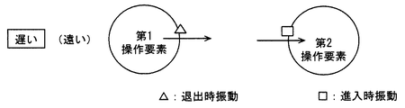
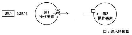
但し、上述した振動のさせ方では、指先を速く動かしてなぞり操作した場合、退出時振動の直後に進入時振動が為されることとなる。この場合、退出時振動と進入時振動とが間隔を空けずに連続して為されるので、ユーザは、退出時振動と進入時振動とを識別できないか、或いは、連続した別の振動と認識することとなる。つまり、振動による報知内容をユーザが認識できなくなる、といった問題が生じる。 However, in the above-described vibration method, when the fingertip is moved quickly and the tracing operation is performed, the vibration at the time of entry is made immediately after the vibration at the time of leaving. In this case, since the vibration at the time of exit and the vibration at the time of entry are continuously made without any interval, the user cannot distinguish between the vibration at the time of exit and the vibration at the time of entry, or recognize it as another continuous vibration. Will be. That is, there arises a problem that the user cannot recognize the notification content due to vibration.
この問題に対し、特許文献1には、退出時振動を実施してから所定時間が経過するまでは進入時振動を禁止させる振動制御が記載されている。この振動制御によれば、退出時から進入時までが所定時間未満となるような速い動きでなぞり操作した場合には、退出時振動の後の進入時振動が禁止されることとなり、上記問題については解消される。
To deal with this problem,
しかしながら、上記振動制御では、指先を速く動かしてなぞり操作すると、退出時振動は有るものの進入時振動は無い。そのため、ユーザが所望する第2操作要素へ指先が進入できている場合、および進入できていない場合のいずれであっても、指先を速く動かすと進入時振動が無いので、ユーザは、所望する第2操作要素へ指先が進入できているか否かを認識できない。 However, in the vibration control described above, when the fingertip is moved quickly and the tracing operation is performed, there is vibration at the time of exit, but there is no vibration at the time of entry. Therefore, even if the fingertip can enter the second operation element desired by the user, or when the fingertip is not able to enter, if the fingertip is moved quickly, there is no vibration at the time of entry. 2. It is not possible to recognize whether or not the fingertip can enter the operation element.
そして、操作要素と指先との位置関係を概ね把握した状態でブラインド操作する慣れたユーザは、なぞり操作する指先の動きが速くなる傾向にある。したがって、ブラインド操作に慣れたユーザにとっては、第1操作要素から退出できているかについての不安よりも、第2操作要素へ進入できているかについての不安の方が大きい。そのため、指先を速く動かす慣れたユーザにとっては、退出時振動よりも進入時振動の方が有用である。よって、進入時振動が無くなる上記振動制御では、ユーザの期待に十分に応えることができず、有用性が低い。 A user who is used to performing a blind operation in a state in which the positional relationship between the operation element and the fingertip is generally understood tends to increase the movement of the fingertip for the tracing operation. Therefore, the user who is accustomed to the blind operation is more worried about whether the user can enter the second operation element than the user who can exit the first operation element. Therefore, the vibration at the time of entry is more useful than the vibration at the time of exit for a user who is accustomed to moving the fingertip quickly. Therefore, the vibration control that eliminates the vibration at the time of entry cannot sufficiently meet the user's expectation, and is less useful.
本発明は、上記問題を鑑みてなされたもので、その目的は、振動による報知内容をユーザが認識しやすく、かつ、指先を速く動かすユーザにとっての有用性が高い車載操作装置を提供することにある。 The present invention has been made in view of the above problems, and an object of the present invention is to provide an in-vehicle operation device that is easy for a user to recognize notification contents due to vibration and highly useful for a user who moves a fingertip quickly. is there.
ここに開示される発明は上記目的を達成するために以下の技術的手段を採用する。なお、特許請求の範囲およびこの項に記載した括弧内の符号は、後述する実施形態に記載の具体的手段との対応関係を示すものであって、発明の技術的範囲を限定するものではない。 The invention disclosed herein employs the following technical means to achieve the above object. Note that the reference numerals in parentheses described in the claims and in this section indicate the correspondence with the specific means described in the embodiments described later, and do not limit the technical scope of the invention. .
開示される発明のひとつは、
車両に搭載され、ユーザの指先により接触操作される操作面(11a、31a)を有した操作パネル(11、31)と、
操作面に設けられた複数の操作要素(A1、A2、A3、A4、A5、A6)のうち、接触操作されている操作要素に応じた操作信号を出力する出力部(23)と、
操作パネルを振動させることで、接触操作しているユーザへ振動を感じさせる振動機器(14)と、
操作面上における指先の接触位置を検出する位置センサ(12、13)と、
位置センサにより検出された接触位置に応じて振動機器の作動を制御する振動制御部(22)と、
を備える車載操作装置において、
位置センサの検出履歴に基づき、接触位置の移動軌跡を算出する軌跡算出部(S11)と、
複数の操作要素のうちの第1操作要素(A1)の内部から外部へと接触位置が移動した場合に、第1操作要素の内部での移動軌跡に基づき、複数の操作要素のうちの第2操作要素(A2)へ所定時間内に接触位置が到達するか否かを予測する予測部(S13、S14)と、
を備え、
振動制御部は、
第2操作要素の外部から内部へと接触位置が移動した時点で、予測部による予測結果に拘らず振動機器を作動させる進入時振動制御部(S20)と、
予測部による予測が到達を肯定するものである場合には、第1操作要素の内部から外部へと接触位置が移動した時点では、振動機器の作動を保留にして振動させない保留制御部(S16)と、を有する車載操作装置である。
One of the disclosed inventions is
An operation panel (11, 31) having an operation surface (11a, 31a) mounted on a vehicle and operated to be touched by a user's fingertip;
An output unit (23) for outputting an operation signal corresponding to the operation element being touched among the plurality of operation elements (A1, A2, A3, A4, A5, A6) provided on the operation surface;
A vibration device (14) that causes the user who is performing a contact operation to feel vibration by vibrating the operation panel;
A position sensor (12, 13) for detecting the contact position of the fingertip on the operation surface;
A vibration control unit (22) for controlling the operation of the vibration device according to the contact position detected by the position sensor;
In-vehicle operation device comprising:
A locus calculation unit (S11) for calculating a movement locus of the contact position based on the detection history of the position sensor;
When the contact position moves from the inside of the first operating element (A1) of the plurality of operating elements to the outside, the second of the plurality of operating elements is based on the movement trajectory inside the first operating element. A prediction unit (S13, S14) for predicting whether or not the contact position reaches the operation element (A2) within a predetermined time;
With
The vibration control unit
When the contact position moves from the outside to the inside of the second operating element, the on-coming vibration control unit (S20) that operates the vibration device regardless of the prediction result by the prediction unit;
When the prediction by the prediction unit affirms arrival, a hold control unit that keeps the operation of the vibration device on hold and does not vibrate when the contact position moves from the inside of the first operating element to the outside (S16). And an in-vehicle operation device.
上記発明によれば、保留制御部を備えるので、接触位置が第1操作要素から退出した時点では、第2操作要素へ所定時間内に進入すると予測されている場合には振動機器の作動(以下、退出時振動と呼ぶ)を保留にする。よって、第1操作要素から第2操作要素へとなぞり操作するにあたり、ユーザが指先を速く動かした場合には、第2操作要素へ所定時間内に進入すると予測されることとなり、退出時振動が保留される。よって、第1操作要素からの退出を報知する退出時振動と、第2操作要素への進入を報知する進入時振動とが、間隔を空けずに連続して為されることを回避できるので、振動による報知内容をユーザが認識できなくなる、といった問題を低減できる。 According to the above-described invention, since the holding control unit is provided, when the contact position leaves the first operation element, the operation of the vibration device (hereinafter referred to as the second operation element is predicted to enter within the predetermined time). , Called vibration when leaving). Therefore, when the user moves the fingertip quickly to perform the drag operation from the first operation element to the second operation element, it is predicted that the user will enter the second operation element within a predetermined time. Deferred. Therefore, it is possible to avoid that the exit vibration for notifying the exit from the first operation element and the entrance vibration for notifying the entry to the second operation element are continuously made without any interval. It is possible to reduce the problem that the user cannot recognize the notification content due to vibration.
さらに上記発明によれば、進入時振動制御部を備えるので、接触位置が第2操作要素へ進入した時点では、予測部による予測結果に拘らず進入時振動が為される。よって、第2操作要素へ進入する指先の速度が遅い場合は勿論のこと、速い場合にも進入時振動が為される。そして、先述したように、指先を速く動かす慣れたユーザにとっては退出時振動よりも進入時振動の方が有用であるため、上記発明によれば、指先を速く動かすユーザにとっての有用性を高くできる。 Furthermore, according to the above-described invention, since the vibration control unit at the time of entry is provided, when the contact position enters the second operation element, vibration at the time of entry is made regardless of the prediction result by the prediction unit. Therefore, not only when the speed of the fingertip entering the second operating element is slow, but also when the fingertip is fast, vibration during entry is made. As described above, since the vibration at the time of entry is more useful than the vibration at the time of exit for the user who is accustomed to moving the fingertip quickly, according to the above invention, the utility for the user who moves the fingertip can be increased. .
以下、図面を参照しながら発明を実施するための複数の形態を説明する。各形態において、先行する形態で説明した事項に対応する部分には同一の参照符号を付して重複する説明を省略する場合がある。各形態において、構成の一部のみを説明している場合は、構成の他の部分については先行して説明した他の形態を参照し適用することができる。 Hereinafter, a plurality of modes for carrying out the invention will be described with reference to the drawings. In each embodiment, portions corresponding to the matters described in the preceding embodiment may be denoted by the same reference numerals and redundant description may be omitted. In each embodiment, when only a part of the configuration is described, the other configurations described above can be applied to other portions of the configuration.
(第1実施形態)
本実施形態に係る車載操作装置は、図1〜図3に示す入力装置10および図3に示す制御装置20を備える。これらの入力装置10および制御装置20は、車両に搭載されている。
(First embodiment)
The in-vehicle operation device according to the present embodiment includes an
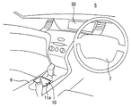
図1に示すように、入力装置10は、車両の室内のうち車両ドライバ(ユーザ)の手が届く範囲内に搭載される。入力装置10による操作内容は表示装置30に表示される。表示装置30はフロントウインドシールド5の近傍に設置されている。入力装置10は、運転席と助手席の間に位置するセンターコンソール6に設置されている。つまり、入力装置10と表示装置30は別々に分離して配置されており、表示装置30は入力装置10よりも上方に配置されている。
As shown in FIG. 1, the
このように、入力装置10と表示装置30を分離して配置することで、車両運転時の視線を大きく動かすことなく表示装置30を見ることができるとともに、運転中のドライバが姿勢を崩さずに、手元に位置する入力装置10を操作できる。
In this way, by disposing the
入力装置10は、車両に搭載された各種機器の作動内容を操作する装置である。機器の具体例としては、ナビゲーション、オーディオ、空調等を行うものが挙げられる。表示装置30には、上述した各種機器に対する操作内容が表示される他、各種機器の作動状態も表示される。
The
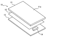
図2に示すように、入力装置10は、操作パネル11、検出シート12および回路基板13を有する。操作パネル11は、ユーザの指先Fにより接触操作される操作面11aを有した板形状のパネルであり、操作面11aが車室内に露出するよう入力装置10はセンターコンソール6に取り付けられている。
As illustrated in FIG. 2, the
操作パネル11に対して車室内の反対側に回路基板13は配置され、回路基板13と操作パネル11の間に検出シート12は配置されている。検出シート12が操作パネル11および回路基板13に対向して配置された状態で、操作パネル11、検出シート12および回路基板13は、図示しないケースに収容されて保持される。また、検出シート12は接着剤で操作パネル11に貼り付けられている。
The
検出シート12は、操作パネル11に対して操作面11aの反対側に配置され、複数の電極(図示せず)を絶縁シートに保持させた構造のシートである。電極は、操作面11aを接触操作する指先Fとの間で静電容量を形成し、その静電容量に応じた検出信号を出力する。例えば、複数本の電極を縦横に格子状に交差して配置されるマトリクス方式の検出シート12が用いられている。
The
回路基板13は、電極から出力される検出信号に基づき、操作面11a上における指先Fの接触位置を検出し、検出した接触位置の情報(位置情報)を制御装置20へ送信する。接触位置の検出および位置情報の送信は、所定周期(例えば10ミリ秒)で繰り返し実行される。例えば、電極から出力される検出信号が所定の閾値を超えて大きい場合に、接触操作有りと判定し、格子状の電極により形成される複数の格子点のうち、閾値を超えている部分の格子点が接触位置であると判定する。そして、閾値を超えている格子点の位置が連続的に移動していく場合に、操作面11aに指先Fを接触させたまま移動させるなぞり操作が為されていると判定する。
The
振動機器14は回路基板13に電気接続されており、操作パネル11、検出シート12および回路基板13を組み合わせた状態において、振動機器14は操作パネル11に接触している。例えば、振動機器14は電気モータおよび振動子を有して構成されており、回路基板13からの通電により電気モータを回転駆動させると、電気モータの回転軸に取り付けられた振動子が回転して振動を生じさせる。したがって、通電の長さや通電のオンオフパターンを変更させることで、振動子の振動パターンが変更される。そして、振動機器14は操作パネル11に接触しているので、操作面11aを接触操作しているユーザは、振動機器14による振動を感じることとなる。
The
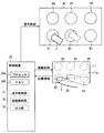
図3に示すように、制御装置20は、プロセッサ20aおよびメモリ20bを有する。プロセッサ20aは、メモリ20bに記憶されているプログラムを演算処理することで、各種の制御を実行する。例えば、車速、車両走行位置、燃料残量等の車両状態を表した情報や、入力装置10から取得した位置情報に基づき、表示装置30の表示内容をプロセッサ20aは制御(表示制御)する。
As illustrated in FIG. 3, the
また、入力装置10から取得した位置情報や表示制御内容に基づき、振動機器14の作動をプロセッサ20aは制御(振動制御)する。この振動制御を実行している時のプロセッサ20aは振動制御部22に相当する。
The
また、入力装置10から取得した位置情報や表示制御内容に基づき、車両に搭載された各種の車載機器へ操作信号を出力(出力制御)する。上記車載機器の具体例としては、車室内を空調する空調装置、車両の走行経路を案内するナビゲート装置、オーディオ装置等が挙げられる。この出力制御を実行している時のプロセッサ20aは出力部23に相当する。
Further, based on the position information and display control content acquired from the
表示装置30は、車両の走行経路を表示するモード、オーディオ装置の作動内容を表示するモード、空調状態を表示するモード等、各種の表示モードに切り替えて表示することが可能である。図3に例示するモードでは、カーソルCおよび複数のアイコンボタンB1、B2、B3、B4、B5、B6が表示されている。カーソルCは、表示装置30の表示領域のうち、入力装置10から出力された位置情報に応じた位置に表示される。そして、所望のアイコンボタンB2上にカーソルCを位置させるよう、ユーザがなぞり操作を行い、その後、そのカーソル位置で指先Fを操作面11aから離すと、そのアイコンボタンB2に割り付けられているコマンドが出力される。このコマンドの具体例として、先述した各種の車載機器を起動させるコマンドが挙げられる。
The
操作面11aの操作領域には、各々のアイコンボタンB1、B2、B3、B4、B5、B6に対応する領域が操作要素A1、A2、A3、A4、A5、A6として設定されている。例えば、図3中の実線に示すように、操作面11aのうち操作要素A1の部分に指先Fを接触させると、操作要素A1に対応するアイコンボタンB1の位置にカーソルCが表示される。その後、図3中の点線に示すように、操作要素A1から操作要素A2まで指先Fをなぞり操作すると、アイコンボタンB1からアイコンボタンB2へとカーソルCの表示位置が移動する。
In the operation area of the
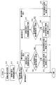
図4は、振動制御部22として機能するプロセッサ20aの処理手順を示すフローチャートであり、入力装置10、制御装置20および表示装置30の電源オン期間中、プロセッサ20aの演算周期等の所定周期で繰り返し実行されるものである。
FIG. 4 is a flowchart showing a processing procedure of the
先ず、図4のステップS10において、入力装置10から送信されてくる位置情報、つまり接触操作している指先Fの接触位置の情報を取得する。続くステップS11では、ステップS10で取得した接触位置の移動軌跡を算出する。接触操作が継続されている場合には、前回算出した移動軌跡に今回算出した移動軌跡を加えて更新していく。ステップS11の処理を実行している時のプロセッサ20aは、位置センサの検出履歴に基づき接触位置の移動軌跡を算出する軌跡算出部に相当する。
First, in step S10 in FIG. 4, the position information transmitted from the
続くステップS12では、操作面11aのうち操作要素A1〜A6として設定された領域と、ステップS10で取得した接触位置との対応関係を判定する。具体的には、以下に説明する「操作要素内」「操作要素から退出」「操作要素外」「操作要素へ進入」のいずれの対応関係であるかを、ステップS10で取得した接触位置およびステップS11で算出した移動軌跡に基づき判定する。
In the subsequent step S12, the correspondence relationship between the areas set as the operation elements A1 to A6 in the
「操作要素内」とは、複数の操作要素A1〜A6の内部、つまり図3の一点鎖線で囲まれた円形領域の内側に接触位置が存在する対応関係である。「操作要素外」とは、複数の操作要素A1〜A6の外部、つまり図3の一点鎖線で囲まれた円形領域の外側に接触位置が存在する対応関係である。「操作要素から退出」とは、前回取得の接触位置では「操作要素内」であったが今回取得の接触位置では「操作要素外」に変化、といった対応関係である。「操作要素へ進入」とは、前回取得の接触位置では「操作要素外」であったが今回取得の接触位置では「操作要素内」に変化、といった対応関係である。 “Inside the operation element” is a correspondence relationship in which the contact position exists inside the plurality of operation elements A1 to A6, that is, inside the circular area surrounded by the one-dot chain line in FIG. “Outside the operating element” is a correspondence relationship in which the contact position exists outside the plurality of operating elements A1 to A6, that is, outside the circular region surrounded by the one-dot chain line in FIG. “Exit from operation element” is a correspondence relationship that “inside operation element” was changed to “outside operation element” at the contact position acquired this time, but “outside operation element” at the contact position acquired this time. “Entering the operation element” is a correspondence relationship that “outside the operation element” was changed to “inside the operation element” at the contact position acquired this time, but “outside the operation element”.
したがって、例えば図3の実線位置から点線位置まで、つまり操作要素A1から操作要素A2までなぞり操作すると、接触位置が操作要素A1にある期間は「操作要素A1内」と判定される。その後、操作要素A1から退出した時点で「操作要素A1から退出」と判定され、その後、操作要素A2に到達するまでの期間は「操作要素外」と判定され、その後、操作要素A2へ進入した時点で「操作要素A2へ進入」と判定される。 Therefore, for example, when a tracing operation is performed from the solid line position to the dotted line position in FIG. 3, that is, from the operation element A1 to the operation element A2, the period in which the contact position is in the operation element A1 is determined as “inside the operation element A1”. After that, it is determined that “exit from the operation element A1” at the time of exiting from the operation element A1, and after that, the period until reaching the operation element A2 is determined as “outside the operation element”, and then the operation element A2 is entered. At this point, it is determined that “enter the operation element A2”.
ステップS12において「操作要素内」と判定された場合、振動機器14を作動させることなく図4の処理を終了する。
If it is determined in step S12 that “inside the operation element”, the processing in FIG. 4 is terminated without operating the
ステップS12において「操作要素から退出」と判定された場合、続くステップS13において、現時点までの接触位置の履歴に基づき今後の移動軌跡を予測する。具体的には、現時点までの移動軌跡に基づき、現時点以降の移動軌跡を予測し、かつ、現時点までの接触位置の移動速度に基づき、現時点から所定時間経過した時点での接触位置を予測する。 If it is determined in step S12 that “exit from the operation element”, in the subsequent step S13, a future movement trajectory is predicted based on the history of the contact position up to the present time. Specifically, based on the movement trajectory up to the present time, the movement trajectory after the current time is predicted, and on the basis of the movement speed of the contact position up to the current time, the contact position when a predetermined time has elapsed from the current time is predicted.
例えば、図5(1)および図6(1)中の実線に示す移動軌跡は、前回処理で操作要素内と判定されていた操作要素A1(第1操作要素)の内部での移動軌跡であり、この移動軌跡に基づき、図5(2)および図6(2)中の点線に示す移動軌跡を予測する。操作要素A1内での移動軌跡は、一定時間毎に取得した接触位置を平均処理して直線化し、その直線の延長線を、予測移動軌跡として算出する。また、操作要素A1内で一定時間毎に取得した接触位置に基づき、操作要素A1内での移動速度を算出し、その移動速度で所定時間経過した時点での予測移動軌跡上の位置を、所定時間後の予測位置とする。 For example, the movement trajectory indicated by the solid line in FIG. 5A and FIG. 6A is the movement trajectory inside the operation element A1 (first operation element) that has been determined to be within the operation element in the previous process. Based on this movement trajectory, the movement trajectory indicated by the dotted line in FIGS. 5 (2) and 6 (2) is predicted. The movement trajectory in the operation element A1 is linearized by averaging the contact positions acquired at regular time intervals, and an extension line of the straight line is calculated as a predicted movement trajectory. Further, based on the contact position acquired at regular time intervals within the operation element A1, the movement speed within the operation element A1 is calculated, and the position on the predicted movement trajectory when the predetermined time elapses at the movement speed is determined as a predetermined value. The predicted position after time.
続くステップS14では、ステップS13で予測した移動軌跡および予測位置と、操作面11a上に設定されている操作要素A1〜A6の位置との関係に基づき、現時点から所定時間内に接触位置が操作要素に到達するか否かを予測する。なお、ステップS13、S14の処理を実行している時のプロセッサ20aは、第1操作要素の内部での移動軌跡に基づき、いずれかの操作要素(第2操作要素)へ所定時間内に接触位置が到達するか否かを予測する予測部に相当する。
In the subsequent step S14, the contact position is determined within the predetermined time from the present time based on the relationship between the movement trajectory and the predicted position predicted in step S13 and the positions of the operation elements A1 to A6 set on the
例えば、図5(3)に示すように、予測位置に至るまでの予測移動軌跡上に、操作要素A1〜A6のいずれか(第2操作要素)が存在する場合には、所定時間内に接触位置が操作要素に到達するといった、到達を肯定する予測結果となる。一方、図6(3)に示すように、予測位置に至るまでの予測移動軌跡上に、第2操作要素が存在しない場合には、所定時間内に接触位置が操作要素に到達しないといった、到達を否定する予測結果となる。 For example, as shown in FIG. 5 (3), when any one of the operation elements A1 to A6 (second operation element) exists on the predicted movement trajectory up to the predicted position, the contact is made within a predetermined time. This is a prediction result that affirms arrival such that the position reaches the operation element. On the other hand, as shown in FIG. 6 (3), when the second operation element does not exist on the predicted movement trajectory up to the predicted position, the contact position does not reach the operation element within a predetermined time. It becomes the prediction result which negates.
ステップS14において到達しないと否定判定された場合には、続くステップS15において振動機器14を作動させ、保留フラグをオフに設定する。これにより、第1操作要素からの退出時点で振動(退出時振動)させることとなり、第1操作要素から指先Fが退出したことをユーザは認識する。なお、ステップS15の処理を実行している時のプロセッサ20aは、到達を否定する予測結果の場合に退出時振動を実行する退出時振動制御部に相当する。
If a negative determination is made in step S14 that it does not reach, the
ステップS14において到達すると肯定判定された場合には、続くステップS16において、第1操作要素からの退出を報知するための振動機器14の作動(退出時振動)を保留にして、保留フラグをオンに設定する。なお、ステップS16の処理を実行している時のプロセッサ20aは、到達を肯定する予測結果の場合に退出時振動を実行せずに保留にする保留制御部に相当する。
If an affirmative determination is made in step S14, in the subsequent step S16, the operation of the vibrating device 14 (vibration upon exit) for notifying the exit from the first operating element is put on hold, and the hold flag is turned on. Set. In addition, the
ステップS12において「操作要素外」と判定された場合、続くステップS17において、現時点までの接触位置の履歴に基づき今後の移動軌跡を予測する。具体的には、ステップS13と同様にして、現時点までの移動軌跡に基づき、現時点以降の移動軌跡を予測し、かつ、現時点までの接触位置の移動速度に基づき、第1操作要素からの退出時点から所定時間経過した時点での接触位置を予測する。つまり、ステップS13における退出時点での予測結果に追加して、その後の「操作要素外」と判定されている期間中にも予測していく。 If it is determined in step S12 that “out of the operation element”, in the subsequent step S17, a future movement trajectory is predicted based on the history of the contact position up to the present time. Specifically, in the same manner as in step S13, based on the movement trajectory up to the present time, the movement trajectory after the current time is predicted, and on the basis of the moving speed of the contact position up to the current time, the exit time from the first operation element The contact position when a predetermined time elapses from is predicted. That is, in addition to the prediction result at the time of exit in step S13, the prediction is performed during the subsequent period when it is determined that “outside the operation element”.
続くステップS18では、ステップS17で追加予測した移動軌跡および予測位置と、操作面11a上に設定されている操作要素A1〜A6の位置との関係に基づき、退出時点から所定時間内に接触位置が操作要素に到達するか否かを予測する。なお、ステップS17、S18の処理を実行している時のプロセッサ20aは、退出時点から現時点までの移動軌跡に基づき、いずれかの操作要素(第2操作要素)へ所定時間内に接触位置が到達するか否かを追加して予測する追加予測部に相当する。
In subsequent step S18, the contact position is determined within a predetermined time from the exit point based on the relationship between the movement locus and predicted position additionally predicted in step S17 and the positions of the operation elements A1 to A6 set on the
ステップS18において到達しないと否定判定された場合には、続くステップS19において、振動機器14を作動させることで、保留中の退出時振動を実施し、保留フラグをオフに設定する。これにより、第1操作要素からの退出時点から僅かに遅れた時点で振動(退出時振動)させることとなり、第1操作要素から指先Fが退出したことをユーザは認識する。ステップS19での退出時振動は、保留フラグをオンになっていることを条件として実施される。なお、ステップS19の処理を実行している時のプロセッサ20aは、到達を否定する追加予測結果の場合に、退出時振動の保留を解除して退出時振動を実行する保留解除部に相当する。
If a negative determination is made in step S18 that it does not reach, in step S19, the
ステップS18において到達すると肯定判定された場合には、振動機器14を作動させることなく、保留フラグの状態もそのままにして、図4の処理を終了する。
If the determination in step S18 is affirmative, the process of FIG. 4 is terminated without operating the
ステップS12において「操作要素へ進入」と判定された場合、続くステップS20において振動機器14を作動させる。これにより、第2操作要素への進入時点で振動(進入時振動)させることとなり、第2操作要素へ指先Fが進入したことをユーザは認識する。また、ステップS20では、保留フラグがオンになっていた場合にはオフに切り替え、オフになっていた場合にはオフの状態を継続させる。なお、ステップS20の処理を実行している時のプロセッサ20aは、予測部による予測結果に拘らず振動機器14を作動させる進入時振動制御部に相当する。
If it is determined in step S12 that “entry to the operation element”, the
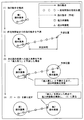
図5は、ステップS14で到達を肯定する予測結果になった場合、かつ、その後のステップS18でも到達を肯定する追加予測結果になった場合の一例である。この例では、図5(3)に示す如く退出時振動を保留にしたまま、図5(4)に示す如く第2操作要素へ進入したため、退出時振動を実施することなく進入時振動を実施している。 FIG. 5 is an example of a case where the prediction result in which the arrival is affirmed in step S14 and the additional prediction result in which the arrival is affirmed also in step S18. In this example, as shown in FIG. 5 (3), the vibration at the time of exit is put on hold and the second operating element is entered as shown in FIG. 5 (4). Therefore, the vibration at the time of entry is executed without performing the vibration at the time of exit. doing.
図6は、ステップS14で到達を否定する予測結果になった場合の一例である。この例では、図6(3)に示す如く退出時振動を退出時点で実施し、図5(4)に示す如く第2操作要素へ進入していないため、進入時振動を実施していない。但し、退出時点から所定時間が経過した後であっても、第2操作要素への進入時点で進入時振動が実施され、その後、図5(1)または図6(1)以降の作動が繰り返されることとなる。 FIG. 6 is an example of a case where the prediction result is negative in step S14. In this example, as shown in FIG. 6 (3), the exit vibration is performed at the time of exit, and as shown in FIG. 5 (4), the second operation element has not been entered, and therefore no entrance vibration is performed. However, even after a predetermined time has elapsed from the time of exit, the vibration at the time of entry is performed at the time of entry into the second operating element, and thereafter, the operation after FIG. 5 (1) or FIG. 6 (1) is repeated. Will be.
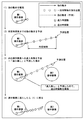
図7〜図10は、図4による振動制御の効果を表した典型例である。図7に示すように、第1操作要素と第2操作要素とが近くに配置されている場合には、なぞり操作速度が遅い場合でも速い場合でも、所定時間以内に第2要素に到達することになるので、退出時振動は実施されずに進入時振動が実施されることとなる。また、図8に示すように、なぞり操作の方向が第2操作要素からずれた方向である場合には、なぞり操作速度が遅い場合でも速い場合でも、退出時振動は実施されるが進入時振動は実施されないこととなる。 7 to 10 are typical examples showing the effect of vibration control according to FIG. As shown in FIG. 7, when the first operation element and the second operation element are arranged close to each other, the second element is reached within a predetermined time regardless of whether the tracing operation speed is slow or fast. Therefore, the vibration at the time of entry is executed without the vibration at the time of exit. In addition, as shown in FIG. 8, when the direction of the tracing operation is shifted from the second operating element, the exiting vibration is performed regardless of whether the tracing operation speed is slow or fast, but the approaching vibration is performed. Will not be implemented.
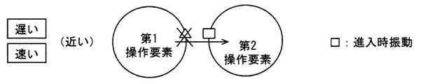
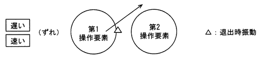
図9および図10に示すように、第1操作要素と第2操作要素とが遠くに配置されている場合には、なぞり操作速度に応じて振動制御の内容が異なってくる。すなわち、図9の如くなぞり操作速度が遅い場合には、所定時間以内に第2要素に到達しなくなるので、退出時振動が実施され、その後、十分に時間が経過した後に進入時振動が実施されることとなる。図10の如くなぞり操作速度が速い場合には、所定時間以内に第2要素に到達することになるので、退出時振動は実施されずに進入時振動が実施されることとなる。 As shown in FIGS. 9 and 10, when the first operation element and the second operation element are arranged far away, the contents of the vibration control differ depending on the tracing operation speed. That is, when the tracing operation speed is slow as shown in FIG. 9, the second element is not reached within a predetermined time, so that the vibration at the time of exit is performed, and then the vibration at the time of entry is performed after sufficient time has passed. The Rukoto. When the tracing operation speed is fast as shown in FIG. 10, the second element is reached within a predetermined time, so that the exit vibration is performed without performing the exit vibration.
以上により、本実施形態によれば、ステップS16による保留制御部を備えるので、接触位置が第1操作要素から退出した時点では、第2操作要素へ所定時間内に進入すると予測されている場合には退出時振動を保留にして振動させない。よって、第1操作要素から第2操作要素へとなぞり操作するにあたり、例えば図10に例示するようにユーザが指先Fを速く動かした場合には、第2操作要素へ所定時間内に進入すると予測されることとなり、退出時振動が保留される。よって、第1操作要素からの退出を報知する退出時振動と、第2操作要素への進入を報知する進入時振動とが、間隔を空けずに連続して為されることを回避できるので、振動による報知内容をユーザが認識できなくなる、といった問題を解消できる。 As described above, according to the present embodiment, since the holding control unit according to step S16 is provided, when the contact position is predicted to enter the second operation element within a predetermined time when the contact position leaves the first operation element. Does not vibrate with leaving vibration on hold. Therefore, when the user performs the drag operation from the first operation element to the second operation element, for example, when the user moves the fingertip F quickly as illustrated in FIG. 10, it is predicted that the user will enter the second operation element within a predetermined time. The vibration at the time of leaving is suspended. Therefore, it is possible to avoid that the exit vibration for notifying the exit from the first operation element and the entrance vibration for notifying the entry to the second operation element are continuously made without any interval. It is possible to solve the problem that the user cannot recognize the notification content due to vibration.
さらに本実施形態によれば、ステップS20による進入時振動制御部を備えるので、接触位置が第2操作要素へ進入した時点では、ステップS13、S14による予測部の予測結果に拘らず進入時振動が為される。よって、第2操作要素へ進入する指先Fの速度が遅い場合(図9参照)は勿論のこと、速い場合(図10参照)にも進入時振動が為される。そして、先述したように、指先Fを速く動かす慣れたユーザにとっては退出時振動よりも進入時振動の方が有用であるため、本実施形態によれば、指先Fを速く動かすユーザにとっての有用性を高くできる。 Furthermore, according to this embodiment, since the vibration control part at the time of approach by step S20 is provided, at the time when the contact position has entered the second operation element, the vibration at the time of entry is generated regardless of the prediction result of the prediction part by steps S13 and S14. Done. Therefore, not only when the speed of the fingertip F entering the second operating element is slow (see FIG. 9), but also when the speed is fast (see FIG. 10), vibrations during entry are made. As described above, since the vibration at the time of entry is more useful than the vibration at the time of exit for the user who is accustomed to moving the fingertip F quickly, according to the present embodiment, the utility for the user who moves the fingertip F quickly is useful. Can be high.
さらに本実施形態によれば、振動制御部22は、ステップS15による退出時振動制御部を有する。この退出時振動制御部は、ステップS13、S14による予測部の予測結果が到達を否定するものである場合には、第1操作要素の内部から外部へと接触位置が移動した退出時点で振動機器14を作動(退出時振動)させる。そのため、退出時振動と進入時振動とが間隔を空けずに連続して為されるおそれのない場合に退出時振動を実施するので、報知内容をユーザが認識できなくなるといった問題を招くこと無く、第1操作要素からの退出をユーザに認識させることができる。
Furthermore, according to the present embodiment, the
さらに本実施形態によれば、ステップS17、S18による追加予測部を備えるとともに、振動制御部22は、ステップS19による保留解除部を備える。追加予測部は、第1操作要素および第2操作要素の外部に接触位置がある場合に、ステップS13、S14による予測が為されてから現時点までの移動軌跡に基づき、第2操作要素へ接触位置が到達するか否かを追加して予測する。保留解除部は、追加予測部による追加予測が到達を否定するものである場合には、保留制御部による保留を解除して振動機器14を作動(退出時振動)させる。
Furthermore, according to this embodiment, while providing the additional prediction part by step S17, S18, the
そのため、第1操作要素からの退出時点では到達すると予測されて退出時振動が保留にされている場合において、その後のなぞり操作の方向や速度が変化した場合に、その変化に応じて退出時振動の保留を解除できる。例えば、退出時点以降に、なぞり操作方向が第2操作要素からずれた場合やなぞり速度が遅くなった場合には、所定時間内に第2操作要素に到達できなくなる状況に変化する。そして、このように変化した場合には、退出時振動の保留を解除して退出時振動を実施するので、状況の変化に応じて、報知内容をユーザが認識できなくなるといった問題を招くこと無く、第1操作要素からの退出をユーザに認識させるように対応できる。 Therefore, when the exit vibration is put on hold when predicted to be reached when leaving the first operating element, if the direction or speed of the subsequent tracing operation changes, the exit vibration according to the change Can be released. For example, when the tracing operation direction deviates from the second operation element or the tracing speed becomes slow after the exit time, the situation changes to a situation where the second operation element cannot be reached within a predetermined time. And, in the case of such changes, since the suspension of the exit vibration is canceled and the exit vibration is performed, the notification content cannot be recognized by the user according to the change in the situation, without causing a problem. It can cope with making a user recognize exit from the 1st operation element.
さらに本実施形態によれば、振動制御部22は、追加予測部による追加予測が到達を肯定するものである場合には、保留制御部による保留を継続させる。そのため、退出時振動と進入時振動とが間隔を空けずに連続して為されることの回避の確実性を向上できる。
Further, according to the present embodiment, the
(第2実施形態)
上記第1実施形態では、図1に示すように入力装置10と表示装置30とが分離して配置されている。これに対し本実施形態では、図11に示すように、入力装置と表示装置とを一体化させた表示機能付き入力装置100(図11参照)を、入力装置10および表示装置30に置き換えている。つまり、本実施形態に係る車載操作装置は、表示機能付き入力装置100および制御装置20を備える。この入力装置100は、インストルメントパネルのうち、図1に示す表示装置30と同じ位置に配置されている。
(Second Embodiment)
In the first embodiment, as shown in FIG. 1, the
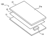
入力装置100は、表示パネル31、検出シート12および回路基板13を有する。表示パネル31は、液晶を保持する液晶層、液晶に電圧を印加する電極層等を有し、図示しないバックライトを光源として画像を表示する。表示パネル31の表示面は、ユーザの指先Fにより接触操作される操作面31aとして機能し、表示パネル31は操作パネルに相当する。検出シート12は表示パネル31の背面に接着剤で貼り付けられている。表示パネル31、検出シート12および回路基板13は、図示しないケースに収容されて保持される。
The
表示パネル31、検出シート12および回路基板13を組み合わせた状態において、振動機器14は表示パネル31に接触している。そのため、操作面31aを接触操作しているユーザは、振動機器14による振動を感じることとなる。制御装置20による振動制御および表示制御等の制御内容は、上記第1実施形態と同じである。よって、本実施形態によっても、上記第1実施形態と同様の効果が発揮される。
In a state where the
(他の実施形態)
以上、発明の好ましい実施形態について説明したが、発明は上述した実施形態に何ら制限されることなく、以下に例示するように種々変形して実施することが可能である。各実施形態で具体的に組合せが可能であることを明示している部分同士の組合せばかりではなく、特に組合せに支障が生じなければ、明示してなくとも実施形態同士を部分的に組み合せることも可能である。
(Other embodiments)
The preferred embodiments of the present invention have been described above, but the present invention is not limited to the above-described embodiments, and various modifications can be made as illustrated below. Not only combinations of parts that clearly show that combinations are possible in each embodiment, but also combinations of the embodiments even if they are not explicitly stated unless there is a problem with the combination. Is also possible.
上記第1実施形態では、操作面11aのうちの特定の領域を操作要素A1〜A6として設定しているが、これらの領域の大きさ、形状、位置、数などを、表示装置30や表示パネル31での表示内容に応じて変更させてもよい。
In the first embodiment, specific areas of the
上記第1実施形態では、ステップS17、S18による追加予測部を備えさせているが、この追加予測部を廃止してもよい。この場合、退出時点での予測結果を変更させないので、退出時点で退出時振動を保留させた場合には、次回の進入が検出されるまでは保留のままとなる。つまり、この場合の保留は、退出時振動を禁止することを意味する。 In the said 1st Embodiment, although the additional prediction part by step S17, S18 is provided, this additional prediction part may be abolished. In this case, since the prediction result at the time of leaving is not changed, if the vibration at the time of leaving is held at the time of leaving, it remains on hold until the next entry is detected. In other words, the hold in this case means that the vibration at the time of leaving is prohibited.
上記第1実施形態での説明では、複数の操作要素A1〜A6のうちの左下に位置する操作要素A1を第1操作要素として説明したが、これら以外の操作要素を第1操作要素としてもよい。また、上記第1実施形態での説明では、複数の操作要素A1〜A6のうちの特定の操作要素A2を第2操作要素として説明したが、これら以外の操作要素を第2操作要素としてもよい。 In the description of the first embodiment, the operation element A1 located at the lower left of the plurality of operation elements A1 to A6 has been described as the first operation element, but other operation elements may be used as the first operation element. . In the description of the first embodiment, the specific operation element A2 among the plurality of operation elements A1 to A6 has been described as the second operation element, but other operation elements may be used as the second operation element. .
上記第1実施形態では、検出シート12および回路基板13による静電容量式の位置センサを採用している。これに対し、接触位置に応じて電気抵抗が変化する抵抗式の位置センサを採用してもよい。上記第1実施形態では、電気モータおよび振動子による振動機器14を採用しているが、ピエゾ素子を用いた振動機器を採用してもよい。
In the first embodiment, a capacitance type position sensor using the
制御装置20が提供する手段および/または機能は、実体的な記憶媒体に記録されたソフトウェアおよびそれを実行するコンピュータ、ソフトウェアのみ、ハードウェアのみ、あるいはそれらの組合せによって提供することができる。例えば、制御装置20がハードウェアである電子回路によって提供される場合、それは多数の論理回路を含むデジタル回路、またはアナログ回路によって提供することができる。
The means and / or function provided by the
11a、31a…操作面、11…操作パネル、14…振動機器、22…振動制御部、23…出力部、31…表示パネル(操作パネル)、S11…軌跡算出部、S13、S14…予測部、S16…保留制御部、S20…進入時振動制御部、A1、A2、A3、A4、A5、A6…操作要素。
DESCRIPTION OF
Claims (4)
前記操作面に設けられた複数の操作要素(A1、A2、A3、A4、A5、A6)のうち、接触操作されている操作要素に応じた操作信号を出力する出力部(23)と、
前記操作パネルを振動させることで、接触操作している前記ユーザへ振動を感じさせる振動機器(14)と、
前記操作面上における前記指先の接触位置を検出する位置センサ(12、13)と、
前記位置センサにより検出された接触位置に応じて前記振動機器の作動を制御する振動制御部(22)と、
を備える車載操作装置において、
前記位置センサの検出履歴に基づき、前記接触位置の移動軌跡を算出する軌跡算出部(S11)と、
複数の前記操作要素のうちの第1操作要素(A1)の内部から外部へと前記接触位置が移動した場合に、前記第1操作要素の内部での前記移動軌跡に基づき、複数の前記操作要素のうちの第2操作要素(A2)へ所定時間内に前記接触位置が到達するか否かを予測する予測部(S13、S14)と、
を備え、
前記振動制御部は、
前記第2操作要素の外部から内部へと前記接触位置が移動した時点で、前記予測部による予測結果に拘らず前記振動機器を作動させる進入時振動制御部(S20)と、
前記予測部による予測が前記到達を肯定するものである場合には、前記第1操作要素の内部から外部へと前記接触位置が移動した時点では、前記振動機器の作動を保留にして振動させない保留制御部(S16)と、
を有する車載操作装置。 An operation panel (11, 31) having an operation surface (11a, 31a) mounted on a vehicle and operated to be touched by a user's fingertip;
An output unit (23) for outputting an operation signal corresponding to the operation element being touched among the plurality of operation elements (A1, A2, A3, A4, A5, A6) provided on the operation surface;
A vibration device (14) that causes the user who is performing a contact operation to feel vibration by vibrating the operation panel;
A position sensor (12, 13) for detecting a contact position of the fingertip on the operation surface;
A vibration control unit (22) for controlling the operation of the vibration device according to the contact position detected by the position sensor;
In-vehicle operation device comprising:
A locus calculation unit (S11) for calculating a movement locus of the contact position based on the detection history of the position sensor;
When the contact position moves from the inside of the first operating element (A1) of the plurality of operating elements to the outside, a plurality of the operating elements are based on the movement trajectory inside the first operating element. A predicting unit (S13, S14) for predicting whether or not the contact position reaches the second operating element (A2) of the first operating element within a predetermined time;
With
The vibration control unit
When the contact position moves from the outside to the inside of the second operating element, the on-coming vibration control unit (S20) that operates the vibration device regardless of the prediction result by the prediction unit;
When the prediction by the prediction unit affirms the arrival, when the contact position is moved from the inside of the first operation element to the outside, the operation of the vibration device is suspended and the vibration is not vibrated. A control unit (S16);
In-vehicle operation device having
前記予測部による予測が前記到達を否定するものである場合には、前記第1操作要素の内部から外部へと前記接触位置が移動した時点で、前記振動機器を作動させる退出時振動制御部(S15)を有する請求項1に記載の車載操作装置。 The vibration control unit
When the prediction by the prediction unit denies the arrival, the exit vibration control unit that activates the vibration device when the contact position moves from the inside of the first operation element to the outside ( The in-vehicle operation device according to claim 1 having S15).
前記振動制御部は、
前記追加予測部による追加予測が前記到達を否定するものである場合には、前記保留制御部による保留を解除して前記振動機器を作動させる保留解除部(S19)を有する請求項1または2に記載の車載操作装置。 When the contact position is outside the first operation element and the second operation element, the contact position is moved to the second operation element based on the movement locus from the prediction by the prediction unit to the current time. Including an additional prediction unit (S17, S18) for predicting whether or not
The vibration control unit
The holding cancellation part (S19) which cancels | releases the holding | maintenance by the said holding | maintenance control part, and operates the said vibration equipment when the additional prediction by the said additional prediction part denies the said arrival. The on-vehicle operation device described.
Priority Applications (3)
| Application Number | Priority Date | Filing Date | Title |
|---|---|---|---|
| JP2016086272A JP6519519B2 (en) | 2016-04-22 | 2016-04-22 | In-vehicle controller |
| PCT/JP2017/013163 WO2017183408A1 (en) | 2016-04-22 | 2017-03-30 | Car onboard operation device |
| US16/095,247 US10558310B2 (en) | 2016-04-22 | 2017-03-30 | Onboard operation apparatus |
Applications Claiming Priority (1)
| Application Number | Priority Date | Filing Date | Title |
|---|---|---|---|
| JP2016086272A JP6519519B2 (en) | 2016-04-22 | 2016-04-22 | In-vehicle controller |
Publications (2)
| Publication Number | Publication Date |
|---|---|
| JP2017194918A true JP2017194918A (en) | 2017-10-26 |
| JP6519519B2 JP6519519B2 (en) | 2019-05-29 |
Family
ID=60115920
Family Applications (1)
| Application Number | Title | Priority Date | Filing Date |
|---|---|---|---|
| JP2016086272A Expired - Fee Related JP6519519B2 (en) | 2016-04-22 | 2016-04-22 | In-vehicle controller |
Country Status (3)
| Country | Link |
|---|---|
| US (1) | US10558310B2 (en) |
| JP (1) | JP6519519B2 (en) |
| WO (1) | WO2017183408A1 (en) |
Cited By (1)
| Publication number | Priority date | Publication date | Assignee | Title |
|---|---|---|---|---|
| CN110580079A (en) * | 2018-06-11 | 2019-12-17 | 联想(新加坡)私人有限公司 | Electronic equipment |
Families Citing this family (4)
| Publication number | Priority date | Publication date | Assignee | Title |
|---|---|---|---|---|
| JP6500936B2 (en) | 2016-07-20 | 2019-04-17 | 株式会社デンソー | Operating device |
| JP6520856B2 (en) * | 2016-08-02 | 2019-05-29 | 株式会社デンソー | Display operation device |
| DE102017113661B4 (en) * | 2017-06-21 | 2021-03-04 | Bcs Automotive Interface Solutions Gmbh | Motor vehicle operating device |
| JP7660463B2 (en) * | 2021-08-24 | 2025-04-11 | フォルシアクラリオン・エレクトロニクス株式会社 | Information processing device |
Citations (6)
| Publication number | Priority date | Publication date | Assignee | Title |
|---|---|---|---|---|
| US20100169773A1 (en) * | 2008-12-30 | 2010-07-01 | Samsung Electronics Co., Ltd. | Method for providing gui using pointer with sensuous effect that pointer is moved by gravity and electronic apparatus thereof |
| US20120256858A1 (en) * | 2011-04-07 | 2012-10-11 | Kyocera Corporation | Character input device, character-input control method, and storage medium storing character input program |
| JP2013206023A (en) * | 2012-03-28 | 2013-10-07 | Kddi Corp | User interface device, tactile vibration application method and program for applying tactile vibration corresponding to depth/height of tactile object image |
| JP2014102654A (en) * | 2012-11-19 | 2014-06-05 | Aisin Aw Co Ltd | Operation support system, operation support method, and computer program |
| JP2014228890A (en) * | 2013-05-17 | 2014-12-08 | シャープ株式会社 | Touch panel system |
| US20150370329A1 (en) * | 2014-06-19 | 2015-12-24 | Honda Motor Co., Ltd. | Vehicle operation input device |
Family Cites Families (5)
| Publication number | Priority date | Publication date | Assignee | Title |
|---|---|---|---|---|
| JP2011048685A (en) * | 2009-08-27 | 2011-03-10 | Kyocera Corp | Input apparatus |
| JP2013073426A (en) | 2011-09-28 | 2013-04-22 | Tokai Rika Co Ltd | Display input device |
| JP5641001B2 (en) * | 2012-02-20 | 2014-12-17 | 株式会社デンソー | Display control apparatus and display system |
| JP2014052787A (en) | 2012-09-06 | 2014-03-20 | Tokai Rika Co Ltd | Vibration presentation device |
| DK201670583A1 (en) * | 2016-03-28 | 2017-10-16 | Apple Inc | Keyboard input to an electronic device |
-
2016
- 2016-04-22 JP JP2016086272A patent/JP6519519B2/en not_active Expired - Fee Related
-
2017
- 2017-03-30 US US16/095,247 patent/US10558310B2/en not_active Expired - Fee Related
- 2017-03-30 WO PCT/JP2017/013163 patent/WO2017183408A1/en not_active Ceased
Patent Citations (9)
| Publication number | Priority date | Publication date | Assignee | Title |
|---|---|---|---|---|
| US20100169773A1 (en) * | 2008-12-30 | 2010-07-01 | Samsung Electronics Co., Ltd. | Method for providing gui using pointer with sensuous effect that pointer is moved by gravity and electronic apparatus thereof |
| JP2010157245A (en) * | 2008-12-30 | 2010-07-15 | Samsung Electronics Co Ltd | Method for providing gui using pointer showing sensuous effect to be moved by gravity and electronic equipment to which the same is applied |
| US20120256858A1 (en) * | 2011-04-07 | 2012-10-11 | Kyocera Corporation | Character input device, character-input control method, and storage medium storing character input program |
| JP2012221179A (en) * | 2011-04-07 | 2012-11-12 | Kyocera Corp | Character input device, character input control method and character input program |
| JP2013206023A (en) * | 2012-03-28 | 2013-10-07 | Kddi Corp | User interface device, tactile vibration application method and program for applying tactile vibration corresponding to depth/height of tactile object image |
| JP2014102654A (en) * | 2012-11-19 | 2014-06-05 | Aisin Aw Co Ltd | Operation support system, operation support method, and computer program |
| JP2014228890A (en) * | 2013-05-17 | 2014-12-08 | シャープ株式会社 | Touch panel system |
| US20150370329A1 (en) * | 2014-06-19 | 2015-12-24 | Honda Motor Co., Ltd. | Vehicle operation input device |
| JP2016004541A (en) * | 2014-06-19 | 2016-01-12 | 本田技研工業株式会社 | Vehicle operation input device |
Cited By (1)
| Publication number | Priority date | Publication date | Assignee | Title |
|---|---|---|---|---|
| CN110580079A (en) * | 2018-06-11 | 2019-12-17 | 联想(新加坡)私人有限公司 | Electronic equipment |
Also Published As
| Publication number | Publication date |
|---|---|
| WO2017183408A1 (en) | 2017-10-26 |
| JP6519519B2 (en) | 2019-05-29 |
| US10558310B2 (en) | 2020-02-11 |
| US20190138126A1 (en) | 2019-05-09 |
Similar Documents
| Publication | Publication Date | Title |
|---|---|---|
| JP5862601B2 (en) | Interface system for car drivers | |
| US9442619B2 (en) | Method and device for providing a user interface, in particular in a vehicle | |
| JP2017194918A (en) | Car onboard operation device | |
| JP7567619B2 (en) | Operation input device | |
| WO2013029257A1 (en) | Vehicle's interactive system | |
| CN104039599A (en) | On-board apparatus | |
| JP2007310496A (en) | Touch operation input device | |
| JP2014203348A (en) | Input device for in-vehicle equipment | |
| JP2013190850A (en) | Display device | |
| CN109564469B (en) | Display operating device | |
| CN110832437A (en) | Operation part control device and operation part control method | |
| JP5946806B2 (en) | Touch switch module | |
| CN104467788A (en) | Touch switch module | |
| JP6477123B2 (en) | Operation system | |
| JP6217535B2 (en) | Vehicle input device | |
| JP6123474B2 (en) | Driving evaluation device | |
| US12050737B2 (en) | Operation device enabling both push and swipe operation | |
| US11402921B2 (en) | Operation control apparatus | |
| JP2015118424A (en) | Information processing device | |
| JP2009214681A (en) | Remote control system | |
| CN115817165A (en) | Display control device for vehicle, display system for vehicle, display method, and computer-readable medium having program recorded thereon | |
| JP2018128968A (en) | VEHICLE INPUT DEVICE AND CONTROL METHOD FOR VEHICLE INPUT DEVICE | |
| JP6828671B2 (en) | Input device | |
| JP2011107900A (en) | Input display device | |
| JP7484756B2 (en) | Display System |
Legal Events
| Date | Code | Title | Description |
|---|---|---|---|
| A621 | Written request for application examination |
Free format text: JAPANESE INTERMEDIATE CODE: A621 Effective date: 20180214 |
|
| TRDD | Decision of grant or rejection written | ||
| A01 | Written decision to grant a patent or to grant a registration (utility model) |
Free format text: JAPANESE INTERMEDIATE CODE: A01 Effective date: 20190326 |
|
| A61 | First payment of annual fees (during grant procedure) |
Free format text: JAPANESE INTERMEDIATE CODE: A61 Effective date: 20190408 |
|
| R151 | Written notification of patent or utility model registration |
Ref document number: 6519519 Country of ref document: JP Free format text: JAPANESE INTERMEDIATE CODE: R151 |
|
| LAPS | Cancellation because of no payment of annual fees |