JP2017194494A - Light source device, illumination device, and projector - Google Patents
Light source device, illumination device, and projector Download PDFInfo
- Publication number
- JP2017194494A JP2017194494A JP2016082709A JP2016082709A JP2017194494A JP 2017194494 A JP2017194494 A JP 2017194494A JP 2016082709 A JP2016082709 A JP 2016082709A JP 2016082709 A JP2016082709 A JP 2016082709A JP 2017194494 A JP2017194494 A JP 2017194494A
- Authority
- JP
- Japan
- Prior art keywords
- light
- bundle
- light source
- light beam
- optical system
- Prior art date
- Legal status (The legal status is an assumption and is not a legal conclusion. Google has not performed a legal analysis and makes no representation as to the accuracy of the status listed.)
- Pending
Links
Images


Abstract
Description
本発明は、光源装置、照明装置及びプロジェクターに関するものである。 The present invention relates to a light source device, a lighting device, and a projector.
近年、プロジェクターにおいて、高輝度且つ高出力な光が得られるレーザー光源が用いられている。例えば、下記特許文献1には、偏光子及び偏光プリズムを用いて4つの光源ユニットから射出した光を合成するプロジェクターが開示されている。 In recent years, laser light sources capable of obtaining light with high brightness and high output have been used in projectors. For example, Patent Document 1 below discloses a projector that combines light emitted from four light source units using a polarizer and a polarizing prism.
しかしながら、上記プロジェクターにおいては、互いの太さが同じ2本の光線束を合成しており、互いの太さが異なる2本の光線束を効率良く合成することについては想定されていなかった。そのため、互いの太さが異なる2本の光線束を合成する際、合成光線束の太さの拡大を低減しつつ、効率的に合成することが可能な新たな技術の提供が望まれている。 However, in the projector described above, two light bundles having the same thickness are combined, and it has not been assumed to efficiently combine two light bundles having different thicknesses. Therefore, when two light bundles having different thicknesses are combined, it is desired to provide a new technique that can be efficiently combined while reducing the expansion of the combined light bundle thickness. .
本発明の一つの態様は、上記の課題を解決するためになされたものであり、合成光線束の太さの拡大を低減しつつ、該合成光線束を効率的に生成できる、光源装置を提供することを目的の一つとする。本発明の一つの態様は、上記の光源装置を備え、小型の照明装置を提供することを目的の一つとする。本発明の一つの態様は、上記の照明装置を備え、小型のプロジェクターを提供することを目的の一つとする。 One aspect of the present invention has been made to solve the above-described problem, and provides a light source device capable of efficiently generating the combined light bundle while reducing the increase in the thickness of the combined light bundle. One of the purposes is to do. One aspect of the present invention is to provide a small lighting device including the light source device described above. An object of one embodiment of the present invention is to provide a small projector including the above lighting device.
本発明の第1態様に従えば、第1の光線束を射出する第1の光源部と、前記第1の光線束よりも太い第2の光線束を射出する第2の光源部と、前記第1の光線束と前記第2の光線束とからなる合成光線束を形成して射出する光合成素子と、を備えた光源装置であって、前記光合成素子は、前記第1の光線束が前記第2の光線束と交わっている領域において、少なくとも前記第1の光線束が入射するように選択的に設けられた光機能性膜を備え、前記光機能性膜は、前記第1の光線束を反射するとともに前記第2の光線束を透過させ、前記合成光線束の断面において、前記第1の光線束は前記第2の光線束と重なっている光源装置が提供される。 According to the first aspect of the present invention, the first light source unit that emits the first light beam, the second light source unit that emits the second light beam thicker than the first light beam, A light combining device that forms and emits a combined light bundle composed of a first light bundle and the second light bundle, wherein the first light bundle is the light source device. An optical functional film selectively provided so that at least the first light bundle is incident in a region intersecting with the second light bundle, and the optical functional film includes the first light bundle; And a light source device that transmits the second light bundle and that overlaps the second light bundle in the cross section of the combined light bundle.
第1態様に係る光源装置によれば、少なくとも第1の光線束を入射させるように選択的に光機能性膜を配置したことで、第2の光線束のうち光機能性膜に入射する成分の割合を低減することができる。よって、光機能性膜に入射することによって生じる第2の光線束のロスが低減されるので、第1の光線束及び第2の光線束を効率的に合成することができる。また、合成光線束は、第1の光線束及び第2の光線束が重なった状態とされるので、第1の光線束及び第2の光線束が重ならない場合と比べて、該合成光線束の太さの拡大を低減できる。
したがって、合成光線束の太さの拡大を低減しつつ、該合成光線束を効率的に生成することができる。
According to the light source device according to the first aspect, the light functional film is selectively disposed so that at least the first light beam is incident, so that the component of the second light beam that is incident on the light functional film. Can be reduced. Therefore, since the loss of the second light flux caused by entering the optical functional film is reduced, the first light flux and the second light flux can be efficiently synthesized. Further, since the combined light bundle is in a state where the first light bundle and the second light bundle overlap, the combined light bundle is compared with the case where the first light bundle and the second light bundle do not overlap. The expansion of the thickness can be reduced.
Therefore, it is possible to efficiently generate the combined light bundle while reducing the increase in the thickness of the combined light bundle.
上記第1態様において、前記光機能性膜は、偏光分離膜からなり、前記第1の光線束は、前記光機能性膜に対してS偏光として入射し、前記第2の光線束は、前記光機能性膜に対してP偏光として入射するのが好ましい。
この構成によれば、偏光状態の違いに基づいて、容易に合成光線束を形成することができる。
In the first aspect, the optical functional film is a polarization separation film, the first light bundle is incident on the optical functional film as S-polarized light, and the second light bundle is It is preferable that the light is incident as P-polarized light on the optical functional film.
According to this configuration, a combined light beam can be easily formed based on the difference in polarization state.
上記第1態様において、前記光機能性膜は、ダイクロイック膜からなり、前記第1の光線束の波長域は、前記第2の光線束の波長域と異なっているのが好ましい。
この構成によれば、波長帯の違いに基づいて、容易に合成光線束を形成することができる。
In the first aspect, the optical functional film is preferably a dichroic film, and the wavelength range of the first light beam is preferably different from the wavelength range of the second light beam.
According to this configuration, a combined light beam can be easily formed based on the difference in wavelength band.
本発明の第2態様に従えば、上記第1態様に係る光源装置と、拡散板と、蛍光体層と、前記合成光線束を、前記拡散板に入射する第3の光線束と前記蛍光体層に入射する第4の光線束とに分離する光分離素子と、を備える照明装置が提供される。 According to the second aspect of the present invention, the light source device according to the first aspect, the diffusion plate, the phosphor layer, the synthetic light beam, the third light beam incident on the diffusion plate, and the phosphor. There is provided an illumination device comprising: a light separating element that separates into a fourth light flux incident on the layer.
第2態様に係る照明装置によれば、合成光線束を分離することで、拡散板によって生成される拡散光と蛍光体層によって生成される蛍光とを含んだ照明光を生成することができる。 According to the illuminating device which concerns on a 2nd aspect, the illumination light containing the diffused light produced | generated by the diffuser plate and the fluorescence produced | generated by the fluorescent substance layer can be produced | generated by isolate | separating a synthetic | combination light beam.
上記第2態様において、前記拡散板と前記光分離素子との間の前記第3の光線束の光路上に設けられた第1の集光レンズと、前記蛍光体層と前記光分離素子との間の前記第4の光線束の光路上に設けられた第2の集光レンズと、前記第1の光源部と前記光合成素子との間の前記第1の光線束の光路上に設けられた第1の光均一化素子と、前記第2の光源部と前記光合成素子との間の前記第2の光線束の光路上に設けられた第2の光均一化素子と、をさらに備え、前記第3の光線束は前記第1の光線束からなり、前記第4の光線束は前記第2の光線束からなるのが好ましい。
この構成によれば、蛍光体層及び拡散素子に対して均一な照度分布の光を入射させることができる。よって、明るい照明光を生成することができる。
In the second aspect, the first condenser lens provided on the optical path of the third light bundle between the diffuser plate and the light separation element, the phosphor layer, and the light separation element A second condenser lens provided on the optical path of the fourth light bundle, and an optical path of the first light bundle between the first light source unit and the light combining element. A first light uniformizing element; and a second light uniformizing element provided on an optical path of the second light bundle between the second light source unit and the light combining element, It is preferable that the third light bundle is composed of the first light bundle, and the fourth light bundle is composed of the second light bundle.
According to this configuration, light having a uniform illuminance distribution can be incident on the phosphor layer and the diffusing element. Therefore, bright illumination light can be generated.
本発明の第3態様に従えば、上記第2態様に係る照明装置と、前記照明装置からの光を画像情報に応じて変調することにより画像光を形成する光変調装置と、前記画像光を投射する投射光学系と、を備えるプロジェクターが提供される。 According to the third aspect of the present invention, the illumination device according to the second aspect, a light modulation device that forms image light by modulating light from the illumination device according to image information, and the image light A projection optical system for projecting is provided.
第3態様に係るプロジェクターは、上記第2態様に係る照明装置を備えるので、該プロジェクターの小型化を実現できる。 Since the projector according to the third aspect includes the illumination device according to the second aspect, it is possible to reduce the size of the projector.
以下、本発明の実施の形態について、図面を参照して詳細に説明する。
なお、以下の説明で用いる図面は、特徴をわかりやすくするために、便宜上特徴となる部分を拡大して示している場合があり、各構成要素の寸法比率などが実際と同じであるとは限らない。
Hereinafter, embodiments of the present invention will be described in detail with reference to the drawings.
In addition, in the drawings used in the following description, in order to make the features easy to understand, there are cases where the portions that become the features are enlarged for the sake of convenience, and the dimensional ratios of the respective components are not always the same as the actual ones. Absent.
プロジェクターの一実施形態について説明する。本実施形態のプロジェクターは、スクリーン(被投射面)上にカラー映像を表示する投射型画像表示装置である。プロジェクターは、赤色光、緑色光、青色光の各色光に対応した3つの液晶光変調装置を備えている。プロジェクターは、照明装置の光源として、高輝度・高出力な光が得られる半導体レーザーを備えている。 An embodiment of a projector will be described. The projector according to the present embodiment is a projection type image display device that displays a color image on a screen (projected surface). The projector includes three liquid crystal light modulation devices corresponding to red, green, and blue light. The projector includes a semiconductor laser that can obtain light with high luminance and high output as a light source of the lighting device.
(第1実施形態)
図1は、本実施形態に係るプロジェクターの光学系を示す概略図である。
プロジェクター1は、図1に示すように、照明装置2と、色分離光学系3と、光変調装置4R,光変調装置4G,光変調装置4Bと、合成光学系5と、投射光学系6と、を概略備えている。
(First embodiment)
FIG. 1 is a schematic diagram illustrating an optical system of a projector according to the present embodiment.
As shown in FIG. 1, the projector 1 includes an
本実施形態において、照明装置2は白色の照明光WLを色分離光学系3に向けて射出する。
In the present embodiment, the
色分離光学系3は、照明光WLを赤色光LRと緑色光LGと青色光LBとに分離する。色分離光学系3は、第1のダイクロイックミラー7aおよび第2のダイクロイックミラー7bと、第1の全反射ミラー8a、第2の全反射ミラー8bおよび第3の全反射ミラー8cと、第1のリレーレンズ9aおよび第2のリレーレンズ9bと、を概略備えている。
The color separation
第1のダイクロイックミラー7aは、照明装置2からの照明光WLを赤色光LRと、その他の光(緑色光LG及び青色光LB)とに分離する機能を有する。第1のダイクロイックミラー7aは、分離された赤色光LRを透過するとともに、その他の光(緑色光LGおよび青色光LB)を反射する。一方、第2のダイクロイックミラー7bは、その他の光を緑色光LGと青色光LBとに分離する機能を有する。第2のダイクロイックミラー7bは、分離された緑色光LGを反射するとともに、青色光LBを透過する。
The first
第1の全反射ミラー8aは、赤色光LRの光路中に配置されて、第1のダイクロイックミラー7aを透過した赤色光LRを光変調装置4Rに向けて反射する。一方、第2の全反射ミラー8bおよび第3の全反射ミラー8cは、青色光LBの光路中に配置されて、第2のダイクロイックミラー7bを透過した青色光LBを光変調装置4Bに導く。
緑色光LGは、第2のダイクロイックミラー7bにより光変調装置4Gに向けて反射される。
The first
The green light LG is reflected toward the
第1のリレーレンズ9aおよび第2のリレーレンズ9bは、青色光LBの光路中における第2のダイクロイックミラー7bの下段に配置されている。第1のリレーレンズ9aおよび第2のリレーレンズ9bは、青色光LBの光路長が赤色光LRや緑色光LGの光路長よりも長いことに起因した青色光LBの光損失を補償する機能を有している。
The
光変調装置4Rは、赤色光LRを通過させる間に、赤色光LRを画像情報に応じて変調し、赤色光LRに対応した画像光を形成する。光変調装置4Gは、緑色光LGを通過させる間に、緑色光LGを画像情報に応じて変調し、緑色光LGに対応した画像光を形成する。光変調装置4Bは、青色光LBを通過させる間に、青色光LBを画像情報に応じて変調し、青色光LBに対応した画像光を形成する。
The
光変調装置4R,光変調装置4G,光変調装置4Bには、例えば透過型の液晶パネルが用いられている。また、液晶パネルの入射側および射出側には、一対の偏光板(図示せず)が配置されており、特定の方向の直線偏光光のみを通過させる構成となっている。
For example, a transmissive liquid crystal panel is used for the
光変調装置4R,光変調装置4G,光変調装置4Bの入射側には、それぞれフィールドレンズ10R,フィールドレンズ10G,フィールドレンズ10Bが配置されている。フィールドレンズ10R,フィールドレンズ10G,フィールドレンズ10Bは、それぞれの光変調装置4R,光変調装置4G,光変調装置4Bに入射する赤色光LR,緑色光LG,青色光LBを平行化する。
A
合成光学系5は、赤色光LR,緑色光LG,青色光LBに対応した各画像光を合成し、合成された画像光を投射光学系6に向けて射出する。合成光学系5には、例えばクロスダイクロイックプリズムが用いられている。
The combining
投射光学系6は、投射レンズ群から構成されている。投射光学系6は、合成光学系5により合成された画像光をスクリーンSCRに向けて拡大投射する。これにより、スクリーンSCR上には、拡大されたカラー映像が表示される。
The projection optical system 6 is composed of a projection lens group. The projection optical system 6 enlarges and projects the image light combined by the combining
(照明装置)
次に、上記照明装置2の構成について説明する。
図2は照明装置2の構成を示す図である。
図2に示すように、照明装置2は、照明光としての照明光WLを色分離光学系3に向けて射出する。照明装置2は、光源装置11と、均一照明光学系13とを含む。
(Lighting device)
Next, the structure of the said illuminating
FIG. 2 is a diagram illustrating a configuration of the
As shown in FIG. 2, the
図2に示すように、光源装置11は、第1光源部20Aと、第1のホモジナイザー光学系22と、第2光源部20Bと、導光部21と、第2のホモジナイザー光学系24と、光合成素子14と、第1の位相差板15と、偏光分離素子23と、第1の集光光学系26と、蛍光体ホイール27と、第2の位相差板28と、第2の集光光学系29と、拡散反射素子30とを備える。
As shown in FIG. 2, the
第2光源部20Bと、第2のホモジナイザー光学系24と、光合成素子14と、第1の位相差板15と、偏光分離素子23と、第2の位相差板28と、第1の集光光学系26と、拡散反射素子30とは、光軸ax1上に順次並んで配置されている。蛍光体ホイール27と、第2の集光光学系29と、偏光分離素子23とは、光軸ax2上に順次並んで配置されている。光軸ax1と光軸ax2とは、同一面内にあり、互いに直交する。
Second
また、第1光源部20Aと、第1のホモジナイザー光学系22と、光合成素子14とは、光軸ax1と直交する光軸ax3上に順次並んで配置されている。光軸ax3は光軸ax2と平行、且つ、光軸ax1,ax2とは同一面内にある。
以下、図面において、XYZ座標系を用いることもある。図2において、X方向は光軸ax1と平行であり、Y方向は光軸ax2と平行であり、Z方向はX方向及びY方向にそれぞれ直交する方向である。
Further, the first
Hereinafter, an XYZ coordinate system may be used in the drawings. In FIG. 2, the X direction is parallel to the optical axis ax1, the Y direction is parallel to the optical axis ax2, and the Z direction is a direction orthogonal to the X direction and the Y direction.
第1光源部20Aは、1つの光源ユニット120から構成される。光源ユニット120は、複数の光線BLからなる光線束Kを射出する。光線束Kは特許請求の範囲の「第1の光線束」に対応する。
The first
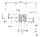
第2光源部20Bは、4つの光源ユニット121〜124から構成され、各光源ユニット121〜124から射出された光線束K1〜K4からなる光線束KAを射出する。図2では、光線束Kと光線束KAの光路をわかりやすくするために、光線束Kと光線束KAを光軸ax1からずらして描いてある。同じ理由で、光線束K1を光線束K2からずらし、光線束K3を光線束K4からずらして描いてある。
光源ユニット121は複数の光線BL1からなる光線束K1を射出し、光源ユニット122は複数の光線BL2からなる光線束K2を射出し、光源ユニット123は複数の光線BL3からなる光線束K3を射出し、光源ユニット124は複数の光線BL4からなる光線束K4を射出する。
The second
The
詳細は後で説明するが、光合成素子14は、光線束Kと、光線束KAとを合成することで合成光線束KGを生成する。光線束K1〜K4から光線束KAを生成する方法についても後で詳述する。
Although details will be described later, the
図3は合成光線束KGの光軸ax1と垂直な断面図である。
光線束K1は、複数の光線BL1の集合からなるが、光線束K1の断面を模式的に矩形で示した。本明細書において、複数の光線BL1の集合を包含する領域が光線束K1の断面に相当する。光線束K2〜K4の断面も模式的に矩形で示した。しかし、断面の形状は矩形に限られない。
光線束KAは光線束K1〜K4の集合からなるが、光線束KAの断面を模式的に矩形で示した。具体的には本明細書において、光線束KAの断面は、光線束K1〜K4各々の最も外側の外形線を結ぶ領域に相当する。従って、本実施形態のように光線束K1〜K4の間に隙間がある場合、光線束KAの断面は該隙間を含む。本実施形態においては、光線束KAは光線束Kよりも太い。光線束KAは特許請求の範囲の「第2の光線束」に対応する。
FIG. 3 is a cross-sectional view perpendicular to the optical axis ax1 of the combined light bundle KG.
The light beam K1 is composed of a set of a plurality of light beams BL1, and the cross section of the light beam K1 is schematically shown as a rectangle. In the present specification, a region including a set of a plurality of light beams BL1 corresponds to a cross section of the light beam K1. The cross sections of the light beams K2 to K4 are also schematically shown as rectangles. However, the cross-sectional shape is not limited to a rectangle.
The light bundle KA is composed of a set of light bundles K1 to K4, and the cross section of the light bundle KA is schematically shown as a rectangle. Specifically, in this specification, the cross section of the light bundle KA corresponds to a region connecting outermost outlines of the light bundles K1 to K4. Therefore, when there is a gap between the light bundles K1 to K4 as in this embodiment, the cross section of the light bundle KA includes the gap. In the present embodiment, the light beam KA is thicker than the light beam K. The beam bundle KA corresponds to the “second beam bundle” in the claims.
光源ユニット120と、光源ユニット121〜124とは、同じ構成を備えており、光線束Kと光線束KAとは波長が同じである。ただし、光線束Kの偏光方向は、光線束KAの偏光方向とは異なっている。光源ユニット120は、後述する光合成素子14が備えている光機能性膜14aに対してS偏光として入射する光線束Kを射出する。光源ユニット121〜124各々は、光機能性膜14aに対してP偏光として入射する光線束K1〜K4を射出する。つまり、光線束KAは、光機能性膜14aに対してP偏光として入射する。
The
第1光源部20Aから射出された光線束Kは、第1のホモジナイザー光学系22を透過して光合成素子14に入射する。第1のホモジナイザー光学系22は、第1光源部20Aと光合成素子14との間の光線束Kの光路上に設けられている。第1のホモジナイザー光学系22は、特許請求の範囲の「第1の光均一化素子」に相当する。
第1のホモジナイザー光学系22は、例えばレンズアレイ22aとレンズアレイ22bとから構成されている。レンズアレイ22aは複数の小レンズ22amを含み、レンズアレイ22bは複数の小レンズ22bmを含む。詳細については後述するが、第1のホモジナイザー光学系22は第1の集光光学系26と協働して、拡散反射素子30における照度分布を均一化させる。
The light beam K emitted from the first
The first homogenizer
第2光源部20Bから射出された光線束KAは、第2のホモジナイザー光学系24を透過して光合成素子14に入射する。第2のホモジナイザー光学系24は、第2光源部20Bと光合成素子14との間の光線束KAの光路上に設けられている。第2のホモジナイザー光学系24は、特許請求の範囲の「第2の光均一化素子」に相当する。
第2のホモジナイザー光学系24は、例えばレンズアレイ24aとレンズアレイ24bとから構成されている。レンズアレイ24aは複数の小レンズ24amを含み、レンズアレイ24bは複数の小レンズ24bmを含む。詳細については後述するが、第2のホモジナイザー光学系24は第2の集光光学系29と協働して、蛍光体ホイール27の蛍光体層33における照度分布を均一化させる。
The light beam KA emitted from the second
The second homogenizer
本実施形態において、第2のホモジナイザー光学系24は、各光源ユニット121〜124に対して共通に設けられているが、各光源ユニット121〜124ごとに個別に設けられていても良い。すなわち、各光源ユニット121〜124に対して、一対のレンズアレイからなるホモジナイザー光学系を設けるようにしても良い。
In the present embodiment, the second homogenizer
光合成素子14は、光線束Kと、光線束KAとを合成することで合成光線束KGを生成し、偏光分離素子23に向けて射出する。光合成素子14は、不図示の保持部材によって保持されている。保持部材は各光線束K1〜K4が入射しない位置に配置するのが望ましい。例えば、保持部材として、Z方向に延びる支柱を光線束K2と光線束K4との間の隙間に配置すればよい(図3参照)。この構成によれば、各光線束K1〜K4のうち保持部材に入射する成分を少なくすることができるので、光線束KAの損失を低減できる。
The
光合成素子14は、光軸ax1,ax3とそれぞれ45度の角度をなすように配置されている。光合成素子14は、光機能性膜14aと、透明基板14bとを備える。本実施形態において、光機能性膜14aは偏光分離膜から構成され、透明基板14bに支持されている。
The
光機能性膜14aは、透明基板14bの一部の領域に設けられている。具体的に、光機能性膜14aは、光線束Kが光線束KAと交わっている領域において、少なくとも光線束Kが入射するように選択的に設けられている。
The optical
図4は光合成素子14に入射した光線束Kと光線束K1〜K4を示す図である。
図4に示すように、光機能性膜14aは、光線束Kの入射位置に設けられている。光機能性膜14aは、光線束K1〜K4の入射位置と部分的に重なっている。
FIG. 4 is a view showing the light bundle K and the light bundles K1 to K4 incident on the
As shown in FIG. 4, the optical
本実施形態において、光線束Kは、光機能性膜14aに対してS偏光として入射するため、光機能性膜14aにより第1の位相差板15に向けて反射される。一方、光線束KAは、光機能性膜14aに対してP偏光として入射するため、光機能性膜14aを透過して第1の位相差板15に向かう。光線束KAのうち光機能性膜14aに入射しない成分は、光合成素子14の透明基板14bを透過して第1の位相差板15に向かう。
In the present embodiment, since the light beam K is incident on the optical
このようにして、光合成素子14は、光線束Kと光線束KAとを合成して、合成光線束KGを生成する。図3に示したように、合成光線束KGの断面において、光線束Kは光線束KAと重なっている。本実施形態において、光線束Kの中心軸Kcと光線束KAの中心軸KAcとは一致しており、光線束Kは光線束KAの内側に位置している。
In this way, the
つまり、合成光線束KGの外形は光線束KAと同じ外形である。よって、本実施形態によれば、互いに太さの異なる2つの光線束K,KAを合成する場合において、合成光線束KGの太さの拡大を最も低減することができる。 In other words, the outer shape of the combined light beam KG is the same as that of the light beam KA. Therefore, according to the present embodiment, when the two light bundles K and KA having different thicknesses are combined, the increase in the thickness of the combined light bundle KG can be reduced most.
合成光線束KGは第1の位相差板15に入射する。第1の位相差板15は1/2波長板から構成される。光機能性膜14aの光入射面および偏光分離素子23の光入射面はZ方向と平行である。そのため、第1の位相差板15を透過した光線束Kは偏光分離素子23に対してP偏光として入射し、第1の位相差板15を透過した光線束KAは偏光分離素子23に対してS偏光として入射する。
The combined light beam KG is incident on the
偏光分離素子23は、光軸ax1、ax2に対して45°の角度をなすように配置される。
The
偏光分離素子23は、S偏光である光線束KAを反射させ、P偏光である光線束Kを透過させる。本実施形態において、偏光分離素子23は、特許請求の範囲の「光分離素子」に相当する。
The
また、偏光分離素子23は、この偏光分離素子23に入射した光のうち、合成光線束KGとは異なる波長帯の光(蛍光YL)を、その偏光状態にかかわらず透過させる色分離機能(波長選択性)を有している。
In addition, the
偏光分離素子23に入射したP偏光の光線束Kは、青色光BLpとして偏光分離素子23を透過して第2の位相差板28に入射する。青色光BLpは、特許請求の範囲の「第3の光線束」に相当する。
The P-polarized light beam K incident on the
第2の位相差板28は1/4波長板からなる。この第2の位相差板28に入射したP偏光(直線偏光)の青色光BLpは、円偏光の青色光BLcに変換された後、第1の集光光学系26に入射する。第1の集光光学系26は、青色光BLcを拡散反射素子30に向かって集光させる。
第1の集光光学系26は、拡散反射素子30と偏光分離素子23との間の青色光BLpの光路上に設けられる。本実施形態において、第1の集光光学系26は、特許請求の範囲の「第1の集光レンズ」に相当する。
The
The first condensing
第1の集光光学系26は、例えば、集光レンズ26a、26bから構成されている。また、第1の集光光学系26は第1のホモジナイザー光学系22と協働して、拡散反射素子30上での青色光BLcによる照度分布を均一化する。本実施形態では、第1の集光光学系26の焦点位置に拡散反射素子30(拡散反射板30A)が配置されている。
具体的に、青色光BLcの被照明領域である拡散反射素子30における光強度分布が均一な状態(いわゆるトップハット分布)となる。
The first condensing
Specifically, the light intensity distribution in the diffuse
拡散反射素子30は、第1の集光光学系26から射出された青色光BLcを偏光分離素子23に向けて拡散反射させる。拡散反射素子30で反射した光を青色光BLc´と称する。拡散反射素子30としては、拡散反射素子30に入射した青色光BLcをランバート反射させるものを用いることが好ましい。
The diffuse
拡散反射素子30は、拡散反射板30Aと、拡散反射板30Aを回転させるためのモーター等の駆動源30Mと、を備えている。拡散反射板30Aは、例えば光反射性を持つ部材の表面に凹凸を形成することで製造することができる。駆動源30Mの回転軸は、光軸ax1と略平行に配置されている。拡散反射板30Aは、回転軸の方向から見て例えば円形に形成されている。
The diffuse
拡散反射板30Aによって反射され、第1の集光光学系26を再び透過した円偏光の青色光BLc´(拡散光)は、再び第2の位相差板28を透過して、S偏光の青色光BLs´となる。S偏光の青色光BLs´は偏光分離素子23で反射される。
The circularly polarized blue light BLc ′ (diffused light) reflected by the diffuse
本実施形態において、光線束KAは、偏光分離素子23に対してS偏光として入射する。そのため、光線束KAは、S偏光の励起光BLsとして第2の集光光学系29に向かって偏光分離素子23で反射される。S偏光の励起光BLsは、特許請求の範囲の「第4の光線束」に相当する。
第2の集光光学系29は、蛍光体ホイール27(蛍光体層33)と偏光分離素子23との間の励起光BLsの光路上に設けられる。本実施形態において、第2の集光光学系29は、特許請求の範囲の「第2の集光レンズ」に相当する。
In the present embodiment, the light beam KA is incident on the
The second condensing
第2の集光光学系29は、例えば集光レンズ29a、29bから構成される(図2参照)。なお、本実施形態では、第2の集光光学系29が2つのレンズから構成される場合を例に挙げたが、1つのレンズ或いは3つ以上のレンズから構成されていても良い。第2の集光光学系29は、励起光BLsを蛍光体ホイール27の蛍光体層33上に集光する機能と、蛍光体層33から射出された後述の蛍光YLをピックアップして平行化する機能とを備える。
The second condensing
第2の集光光学系29は、第2のホモジナイザー光学系24と協同して、蛍光体層33上での励起光BLsによる照度分布を均一化する。
具体的に、励起光BLsの被照明領域である蛍光体層33における光強度分布が均一な状態(いわゆるトップハット分布)となる。よって、明るい蛍光YLを生成することができる。
The second condensing
Specifically, the light intensity distribution in the
本実施形態の蛍光体ホイール27は、いわゆる反射型の回転蛍光板である。
蛍光体ホイール27は、モーター31により回転可能な基板32上にリング状の蛍光体層33を備える。蛍光体ホイール27は、励起光が入射する側と同じ側に向けて蛍光YLを射出する。基板32は、例えば、アルミや銅といった放熱性に優れた金属製の円板から構成されている。なお、本実施形態において、基板32の形状は円形であるが、該基板32の形状は円板状に限るものではない。
The
The
蛍光体層33は、励起光BLsによって励起されて、赤色光及び緑色光を含む蛍光YLを射出する。蛍光体層33は、例えば、YAG系蛍光体である(Y,Gd)3(Al,Ga)5O12:Ceを含有する層からなる。
The
基板32と蛍光体層33との間に反射膜34が設けられている。反射膜34は、蛍光YLを高い効率で反射するように設計されている。そのため、蛍光YLは、蛍光体層33から直接或いは反射膜34で反射されることで、蛍光体層33から第2の集光光学系29に向かって射出される。蛍光YLは第2の集光光学系29により平行光に変換されて、偏光分離素子23を透過する。このように、偏光分離素子23を透過した蛍光YLと偏光分離素子23で反射された青色光BLs´とが合成されることで、白色の照明光WLが生成される。
A
本実施形態によれば、合成光線束KGにおいて、光線束Kの中心軸Kcが光線束KAの中心軸KAcと一致しているため、青色光BLs´と、光線束KAにより生成された蛍光YLとが、互いに良好に重なった状態で合成される。よって、色ムラが低減された照明光WLを生成することができる。 According to this embodiment, since the central axis Kc of the light beam K coincides with the central axis KAc of the light beam KA in the combined light beam KG, the blue light BLs ′ and the fluorescence YL generated by the light beam KA. Are synthesized in a state where they overlap each other well. Therefore, the illumination light WL with reduced color unevenness can be generated.
均一照明光学系13は、第1レンズアレイ125、第2レンズアレイ130、偏光変換素子140及び重畳レンズ150を含む。
The uniform illumination
第1レンズアレイ125は、偏光分離素子23からの照明光WLを複数の部分光束に分割するための複数の第1小レンズ125aを有する。複数の第1小レンズ125aは、光軸ax2と直交する面内にマトリクス状に配列されている。
The
第2レンズアレイ130は、第1レンズアレイ125の複数の第1小レンズ125aに対応する複数の第2小レンズ130aを有する。第2レンズアレイ130は、重畳レンズ150とともに、第1レンズアレイ125の各第1小レンズ125aの像を光変調装置4R,4G,4Bの画像形成領域近傍に結像させる。複数の第2小レンズ130aは光軸ax2に直交する面内にマトリクス状に配列されている。
The
偏光変換素子140は、照明光WLの偏光方向を揃える。偏光変換素子140は、例えば、偏光分離膜と位相差板とミラーとから構成されている。偏光変換素子140は、非偏光である蛍光YLの他方の偏光成分を一方の偏光成分に、例えばP偏光成分をS偏光成分に変換する。
The
重畳レンズ150は、偏光変換素子140からの各部分光束を集光して光変調装置4R,4G,4Bの画像形成領域近傍で互いに重畳させる。第1レンズアレイ125、第2レンズアレイ130及び重畳レンズ150は、画像形成領域における照明光WLの面内光強度分布を均一にするインテグレータ光学系を構成する。
The superimposing
続いて、第1光源部20A及び第2光源部20Bの構成について詳細に説明する。具体的に、各光源ユニット120〜124の構成について説明する。上述のように各光源ユニット120〜124は、射出する光の偏光方向以外、同一の構成を有している。そのため、以下では、光源ユニット120〜124のうち光源ユニット120を例に挙げて、その構造について説明する。
Next, the configuration of the first
図5は光源ユニット120の構成を示す斜視図である。
図5に示すように、光源ユニット120は、複数の発光部40と、該複数の発光部40を支持する放熱器120Hと、を含む。放熱器120Hは、発光部40を冷却するヒートシンクである。放熱器120Hは、本体部60Aおよび支持部材60Bを含む。これら本体部60Aおよび支持部材60Bは、例えば、アルミや銅といった放熱性に優れた金属材料から構成される。
FIG. 5 is a perspective view showing the configuration of the
As shown in FIG. 5, the
本体部60Aは、Z方向における寸法がX方向における寸法よりも大きい板状部材である。複数の支持部材60Bは、本体部60Aの側面60A1の中央部に取り付けられている。各支持部材60Bは、側面60A1のZ方向において、各々の間隔を均等とするように配置されている。すなわち、複数の発光部40は、対応する放熱器120Hの本体部60Aの略中央部に設けられている。
The
各支持部材60Bは板状の部材であって、上面60B1と下面60B2とを有する。上面60B1及び下面60B2の平面形状は略矩形状であって、X方向に長辺を有し、Y方向に短辺を有している。上面60B1はXY平面と平行であり、水平面となっている。
Each
本実施形態において、複数の発光部40は、それぞれ半導体レーザーから構成される。
複数の発光部40は、支持部材60Bの上面60B1に一次元的に実装されている。各発光部40は青色(発光強度のピーク:440nm〜460nm(例えば、445nm))の光ビームからなる光線BLを射出する。
In the present embodiment, the plurality of light emitting
The plurality of light emitting
光源ユニット120は、複数の光線BLを含む光線束Kを射出する。図5では、便宜上、最下段の支持部材60B上に配置される発光部40から射出される光線BLのみを図示するが、光線束Kとは全ての支持部材60B上に配置された発光部40から射出された光線BLを含む。
The
図6は発光部40の要部構成を示す図である。
図6に示すように、発光部40は、光を射出する光射出面40aを有している。光射出面40aは、射出される光の主光線の方向から視て長手方向W1と短手方向W2とを有した、略矩形状の平面形状を有している。
FIG. 6 is a diagram illustrating a main configuration of the
As shown in FIG. 6, the
本実施形態において、光射出面40aの長手方向W1の幅は例えば40μmであり、光射出面40aの短手方向W2の幅は例えば、1μmであるが、光射出面40aの形状はこれに限定されない。なお、図6において、長手方向W1はX方向と平行であり、短手方向W2はZ方向と平行である。
In the present embodiment, the width of the
発光部40から射出された光線BLは、長手方向W1と平行な偏光方向を有する直線偏光からなる。光線BLの短手方向W2への拡がりは、光線BLの長手方向W1への拡がりよりも大きい。そのため、光線BLの断面形状BSは、Z方向(短手方向W2)を長軸方向とした楕円形状となる。
The light beam BL emitted from the
本実施形態において、複数の発光部40は、各発光部40から射出された光線BLの主光線BLaがY方向と平行となるように、上面60B1に実装されている。
In the present embodiment, the plurality of light emitting
本実施形態において、光源ユニット120(複数の発光部40)から射出された光線束Kはコリメート光学系61に入射する。コリメート光学系61は、光線束Kを平行光に変換する。なお、コリメート光学系61は、他の光源ユニット121〜124の後段にもそれぞれ配置されている。
In the present embodiment, the light bundle K emitted from the light source unit 120 (the plurality of light emitting units 40) enters the collimating
図7はコリメート光学系61の概略構成を示す斜視図である。
図7に示すように、コリメート光学系61は、第1のシリンドリカルレンズアレイ50と、第2のシリンドリカルレンズアレイ55とを含む。
FIG. 7 is a perspective view showing a schematic configuration of the collimating
As shown in FIG. 7, the collimating
第1のシリンドリカルレンズアレイ50は、第2のシリンドリカルレンズアレイ55よりも光源ユニット120側に配置されている。第1のシリンドリカルレンズアレイ50は、複数の第1シリンドリカルレンズ51を有する。なお、複数の第1シリンドリカルレンズ51は、各々が一体形成されていても良いし、別体で構成されていても良い。
The first
第1シリンドリカルレンズ51は、X方向に沿う第1の母線51Mと、凸状のレンズ面52と、平坦な裏面53と、を有する。第1の母線51Mは上面60B1と平行である。
本実施形態において、第1シリンドリカルレンズ51は、平凸レンズであるため、製造コストを抑えることが可能である。
The first
In the present embodiment, since the first
本実施形態において、第1シリンドリカルレンズ51は、裏面53を各発光部40の光射出面40aに対向させている。第1シリンドリカルレンズ51の数は支持部材60Bの数に対応する。
In the present embodiment, the first
本実施形態では、図5に示したように、支持部材60Bが5段設けられていることから、第1のシリンドリカルレンズアレイ50は5つの第1シリンドリカルレンズ51から構成されている。
このような構成に基づき、発光部40から射出された光線BLは、対応する第1シリンドリカルレンズ51によりXZ面内において平行化されるようになっている。
In the present embodiment, as shown in FIG. 5, since the support member 60 </ b> B is provided in five stages, the first
Based on such a configuration, the light beam BL emitted from the
一方、第2のシリンドリカルレンズアレイ55は、複数の第2シリンドリカルレンズ56を有する。第2のシリンドリカルレンズアレイ55は、各支持部材60Bに実装された発光部40の数に対応した数の第2シリンドリカルレンズ56を有する。なお、複数の第2シリンドリカルレンズ56は、各々が一体形成されていても良いし、別体で構成されていても良い。
On the other hand, the second
第2シリンドリカルレンズ56は、第2の母線56Mの方向が支持部材60Bの上面60B1と交差するように配置されている。本実施形態では、第2の母線56Mの方向は、上面60B1と直交している。また、第2シリンドリカルレンズ56は、第2の母線56Mが第1シリンドリカルレンズ51の第1の母線51Mの方向と直交している。
The second
第2シリンドリカルレンズ56は、凸状のレンズ面57と、平坦な裏面58とを有する平凸レンズである。
The second
本実施形態において、第2シリンドリカルレンズ56は、裏面58を第1シリンドリカルレンズ51のレンズ面52に対向させている。第2シリンドリカルレンズ56の数は、各上面60B1のX方向に沿って配置される発光部40の数に対応する。
本実施形態においては、図7に示すように、支持部材60Bの上面60B1に発光部40が5個配置されていることから、第2のシリンドリカルレンズアレイ55は5つの第2シリンドリカルレンズ56を有している。
このような構成に基づき、第1シリンドリカルレンズ51を透過した光線BLは、対応する第2シリンドリカルレンズ56によりXY平面内において平行化されるようになっている。
In the present embodiment, the second
In the present embodiment, as shown in FIG. 7, since the five light emitting
Based on such a configuration, the light beam BL transmitted through the first
本実施形態において、第1シリンドリカルレンズ51と第2シリンドリカルレンズ56との間の距離と、第1シリンドリカルレンズ51の屈折力と、第2シリンドリカルレンズ56の屈折力とは、第2シリンドリカルレンズ56を透過した光線BLの断面のアスペクト比が略1となるように設定されていてもよい。この場合、コリメート光学系61を透過した光線BLの断面形状BSは、図6に示した楕円状ではなく、略円形状となる。
In the present embodiment, the distance between the first
このように本実施形態によれば、光源ユニット120は、複数の発光部40から射出した光線BLを2つのシリンドリカルレンズを含むコリメート光学系61によって平行光に変換することで光線束Kを生成する。
As described above, according to the present embodiment, the
同様に、光源ユニット120と同一構成を有する光源ユニット121〜124各々は、複数の発光部40を備えている。光源部20Bは、各々が光源ユニット121〜124に対応する、第1の放熱器121H、第2の放熱器122H、第3の放熱器123H及び第4の放熱器124Hを含む。第1の放熱器121Hは、第1の光源ユニット121を冷却するヒートシンクであり、第2の放熱器122Hは、第2の光源ユニット122を冷却するヒートシンクであり、第3の放熱器123Hは、第3の光源ユニット123を冷却するヒートシンクであり、第4の放熱器124Hは、第4の光源ユニット124を冷却するヒートシンクである。複数の発光部40から射出した光線はコリメート光学系61によって平行光に変換される。
Similarly, each of the
図2に示したように、光源ユニット121は、光軸ax1と平行な方向(−X方向)に沿って光線束K1を射出する。光線束K1は、後述の導光部21を素通りして第2のホモジナイザー光学系24に直接入射するようになっている。
As shown in FIG. 2, the
光源ユニット122は、光線束K2を光軸ax1と直交(交差)する+Y方向に射出する。光源ユニット123は、光線束K3をX方向と直交(交差)する−Y方向に射出する。光源ユニット124は、光線束K4を光軸ax1と平行な方向(−X方向)に射出する。
The
本実施形態において、上記光線束K2〜K4は導光部21を介してホモジナイザー光学系24に入射するようになっている。導光部21は、4つの光線束K1〜K4を合成し、第2のホモジナイザー光学系24へと導く。
In the present embodiment, the light fluxes K <b> 2 to K <b> 4 are incident on the homogenizer
導光部21は、第1反射ミラー21Aと、第2反射ミラー21Bと、第3反射ミラー21Cと、第4反射ミラー21Dとを含む。
The
第1反射ミラー21Aは、光源ユニット122からの光線束K2を光軸ax1と平行な−X方向に反射する。第1反射ミラー21Aは、光線束K2のZ方向の高さを変化させること無く、進行方向を+Y方向から−X方向に向かうように向きを変える。
The first reflecting
第2反射ミラー21Bは、光源ユニット123からの光線束K3を光軸ax1と平行な−X方向に反射する。第2反射ミラー21Bは、光線束K2のZ方向の高さを変化させること無く、進行方向を−Y方向から−X方向に向かうように向きを変える。
The second reflecting
第3反射ミラー21Cは、光源ユニット124からの光線束K4を第4反射ミラー21Dに向けて反射する。第3反射ミラー21Cは、光線束K3のZ方向の高さを変化させること無く、進行方向を−X方向から−Y方向に向かうように向きを変える。
The third reflecting
第4反射ミラー21Dは、第3反射ミラー21Cで反射した光線束K4を光軸ax1と平行な−X方向に反射する。第4反射ミラー21Dは、光線束K4のZ方向の高さを変化させること無く、進行方向を−Y方向から−X方向に向かうように向きを変える。
第4反射ミラー21Dは、Z方向から平面視した際、第2反射ミラー21Bに重なるように、第2反射ミラー21BのZ方向の下方に配置される。
The fourth reflecting
The
本実施形態において、導光部21を構成する各反射ミラー21A〜21Dは、光軸ax1方向(X方向)において同じ位置に配置される。これにより、導光部21は光軸ax1方向におけるサイズが小型化される。
In the present embodiment, the reflecting
図8は−X方向から視た、第2光源部20B及び導光部21の位置関係を示す図である。
図8に示すように、光源ユニット121及び光源ユニット122は、Z方向において、光線束K1,K2の高さを互いに異ならせるように配置されている。
光線束K1は、導光部21を経由せず、−X方向に沿って射出される。光線束K2は、光線束K1の下方に配置された第1反射ミラー21Aにより−X方向に向けて反射される。これにより、光線束K2は、Y方向において略光線束K1と略同じ位置であって、Z方向において光線束K1の下方に配置される。
FIG. 8 is a diagram illustrating a positional relationship between the second light source unit 20 </ b> B and the
As shown in FIG. 8, the
The light beam K1 is emitted along the −X direction without passing through the
光源ユニット123及び光源ユニット124は、Z方向において、光線束K3,K4の高さを互いに異ならせるように配置される。
光源ユニット123は、Y方向において光源ユニット122に向き合うように配置され、Z方向において光源ユニット122の上方に配置される。光源ユニット123において、光線束K3のZ方向における位置は、光線束K1のZ方向における位置と略同一である。光線束K3は、第2反射ミラー21Bにより−X方向に向けて反射される。これにより、光線束K3は、Y方向において略光線束K1と隣り合う位置であって、Z方向において光線束K1と略同じ高さに位置する。
The
The
光源ユニット124は、Y軸に沿った方向において光源ユニット123の隣に配置され、Z軸に沿った方向において光源ユニット123と異なる高さに配置される。光源ユニット124において、光線束K4のZ方向の位置は、光線束K3のZ方向の位置よりも低い。光線束K4は、第3反射ミラー21Cにより−Y方向に向けて反射された後、第4反射ミラー21Dにより−X方向に向けて反射される。
これにより、光線束K4は、Y軸に沿った方向において略光線束K3と略同じ位置であって、Z軸に沿った方向において光線束K3の下方に位置する。また、光線束K4は、Y軸に沿った方向において光線束K2と隣り合う位置であって、Z軸に沿った方向において光線束K2と略同じ高さに位置する。
The
As a result, the light beam K4 is substantially at the same position as the light beam K3 in the direction along the Y axis, and is positioned below the light beam K3 in the direction along the Z axis. The light beam K4 is positioned adjacent to the light beam K2 in the direction along the Y axis and is located at substantially the same height as the light beam K2 in the direction along the Z axis.
以上のようにして、光線束K1〜K4から光線束KAが生成される。本実施形態において、導光部21は反射のみを用いて光線束KAを生成するため、各光線束K1〜K4の偏光状態を乱さない。そのため、光線束KAは光機能性膜14aに対するP偏光から構成されたものとなる。よって、光線束KAは上述のように光機能性膜14aを良好に透過することができる。
As described above, the light flux KA is generated from the light fluxes K1 to K4. In the present embodiment, since the
本実施形態において、光源ユニット121が備える複数の発光部40は、放熱器121Hの本体部(図示略)の略中央に設けられている。光源ユニット124が備える複数の発光部40は、放熱器124Hの本体部(図示略)の略中央に設けられている。例えば、放熱器121H及び放熱器124Hの長辺方向をY方向に沿わせるように、光源ユニット121及び光源ユニット124を配置すると、これら光源ユニット121及び光源ユニット124を挟んで配置される光源ユニット122及び光源ユニット123間の距離を大きくとる必要が生じる。そのため、第2光源部20BにおけるY方向のサイズが大きくなることで、光源装置11及び該光源装置11を含む照明装置2が大型化してしまう。
In the present embodiment, the plurality of light emitting
本実施形態では、放熱器121H及び放熱器124Hの短辺方向をY方向に沿わせるように、光源ユニット121及び光源ユニット124を配置している。すなわち、放熱器121H及び放熱器124Hにおいて、Z方向におけるサイズがY方向におけるサイズよりも大きい。
In the present embodiment, the
これにより、隣り合う放熱器同士の接触を回避しつつ、各放熱器121H,124Hのサイズをできるだけ大きくできる。よって、光源ユニット121及び光源ユニット124の放熱性能を損なうことなく、両方のユニット同士を近づけて配置することで光源装置11を小型化できる。また、光源装置11を含む照明装置2自体の小型化を実現できる。
Thereby, the size of each
以上述べたように、本実施形態の光合成素子14によれば、少なくとも光線束Kが入射するように光機能性膜14aが選択的に配置されているので、光線束KAのうち光機能性膜14aに入射する成分の割合を低減できる。よって、光機能性膜14aに入射することによって生じる光線束KAのロスが低減されるので、光線束K及び光線束KAを効率的に合成して合成光線束KGを生成することができる。
また、本実施形態の光源装置11によれば、合成光線束KGの太さの拡大を低減しつつ、該合成光線束KGを効率的に生成することができる。
As described above, according to the
Further, according to the
本実施形態によれば、合成光線束KGの太さの拡大を低減しつつ、該合成光線束KGを効率的に生成する光源装置11を実現できる。よって、本実施形態のプロジェクター1は、上記光源装置11を備えるので、小型化が可能である。
According to the present embodiment, it is possible to realize the
(第2実施形態)
続いて、第2実施形態のプロジェクターについて説明する。以下では上記実施形態と共通の部材及び構成については同じ符号を付し、その説明については省略若しくは簡略化する。
(Second Embodiment)
Next, the projector according to the second embodiment will be described. In the following, members and configurations common to those of the above embodiment are denoted by the same reference numerals, and descriptions thereof are omitted or simplified.
図9は本実施形態のプロジェクター1Bの概略構成を示す平面図である。
図9に示すように、プロジェクター1Bは、照明装置2Bと、第1のダイクロイックミラー7aと、全反射ミラー7cと、第1の全反射ミラー8aと、第3の全反射ミラー8cと、光変調装置4R,光変調装置4G,光変調装置4Bと、合成光学系5と、投射光学系6とを備えている。全反射ミラー7cは、緑色光LGの光路中に配置されて、第1のダイクロイックミラー7aで反射された緑色光LGを光変調装置4Gに導く。第3の全反射ミラー8cは、照明装置2Bからの青色光LBの光路中に配置されて、該青色光LBを光変調装置4Bに導く。
FIG. 9 is a plan view showing a schematic configuration of the
As shown in FIG. 9, the
照明装置2Bは、青色光LBと、赤色光LRおよび緑色光LGを含んだ黄色光である蛍光YLとを射出する。
The
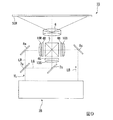
図10は本実施形態の照明装置2Bの概略構成を示す平面図である。
図10に示すように、照明装置2Bは、光源装置11Bと、均一照明光学系13とを含む。照明装置2Bは、第1光源部20Aと、第1のホモジナイザー光学系22と、第2光源部20Bと、導光部21と、第2のホモジナイザー光学系24と、光合成素子14と、第1の位相差板15と、偏光分離素子23と、第1の集光光学系26と、拡散素子126と、第1のピックアップ光学系17と、全反射ミラー18と、第2の集光光学系29と、蛍光体ホイール27Aと、第2のピックアップ光学系16とを備える。
FIG. 10 is a plan view showing a schematic configuration of the
As illustrated in FIG. 10, the
第2光源部20Bと、導光部21と、第2のホモジナイザー光学系24と、光合成素子14と、第1の位相差板15と、偏光分離素子23と、第1の集光光学系26と、拡散素子126と、第1のピックアップ光学系17と、全反射ミラー18とは、光軸ax4上に順次並んで配置されている。
また、偏光分離素子23と、第2の集光光学系29と、蛍光体ホイール27と、第2のピックアップ光学系16と、均一照明光学系13とは、光軸ax6上に順次並んで配置されている。光軸ax4と光軸ax6とは、同一面内にあり、互いに直交する。
The second
The
また、第1光源部20Aと、第1のホモジナイザー光学系22と、光合成素子14とは、光軸ax4と直交する光軸ax5上に順次並んで配置されている。光軸ax5は光軸ax6と平行、且つ、光軸ax4,ax6とは同一面内にある。
Further, the first
本実施形態においても、第1光源部20Aから射出された光線束Kと第2光源部20Bから射出された光線束KAとが光合成素子14において合成されることで合成光線束KGが生成される。本実施形態においても、光線束Kの中心軸Kcと光線束KAの中心軸KAcとが一致している(図4参照)。
Also in the present embodiment, the light bundle K emitted from the first
光線束Kは偏光分離素子23に対してP偏光として入射する。光線束Kは偏光分離素子23および第1の集光光学系26を透過して、青色光BLpとして拡散素子126に入射する。
本実施形態において、拡散素子126は、いわゆる透過型の拡散板である。拡散素子126は、第1の集光光学系26の焦点位置に配置されている。拡散素子126は、例えば、表面に複数のマイクロレンズを形成したガラス板、ホログラフィック拡散板、スリガラスを用いることができる。
The light beam K is incident on the
In the present embodiment, the
拡散素子126を透過した青色光BLp(拡散光)は、第1のピックアップ光学系17によりピックアップされて平行光に変換される。第1のピックアップ光学系17から射出された青色光BLpは、全反射ミラー18および第3の全反射ミラー8cおよびフィールドレンズ10Bを介して、青色光LBとして光変調装置4Bに入射する。
Blue light BLp (diffused light) transmitted through the diffusing
光線束KAは偏光分離素子23に対してS偏光として入射する。光線束KAは偏光分離素子23で反射されて、さらに第2の集光光学系29を透過して、励起光BLsとして蛍光体ホイール27Aの蛍光体層33に入射する。
The light beam KA enters the
本実施形態の蛍光体ホイール27Aは、いわゆる透過型の回転蛍光板である。
蛍光体ホイール27Aは、モーター31により回転可能な基板32A上にリング状の蛍光体層33を備える。蛍光体ホイール27Aは、励起光が入射する側と反対側に向けて蛍光YLを射出する。基板32Aは、例えば、ガラスやプラスチックといった円板状の透明部材から構成されている。なお、本実施形態において、基板32Aの形状は円形であるが、該基板32Aの形状は円板状に限るものではない。
The
The
蛍光体層33から射出された蛍光YLは、第2のピックアップ光学系16によりピックアップされて平行光に変換された後、均一照明光学系13を経てダイクロイックミラー7aによって赤色光LRと緑色光LGとに分離される。これにより、赤色光LR及び緑色光LGは光変調装置4R、4Gの光入射面をそれぞれ均一な明るさで照明する。
Fluorescence YL emitted from the
本実施形態のプロジェクター1Bにおいても、合成光線束KGの太さの拡大を低減しつつ、該合成光線束KGを効率的に生成することができるので、小型化が可能である。
Also in the
なお、本発明の一実施形態を例示して説明したが、本発明は上記実施形態のものに必ずしも限定されるものではなく、本発明の趣旨を逸脱しない範囲において種々の変更を加えることが可能である。 In addition, although one embodiment of the present invention has been illustrated and described, the present invention is not necessarily limited to the above embodiment, and various modifications can be made without departing from the spirit of the present invention. It is.
例えば、上記実施形態では、光線束KAの断面において、光線束K1〜K4は互いに分離されていたが、必ずしも分離されている必要は無い。光線束K1〜K4の合成手段によっては、光線束K1〜K4が部分的に互いに重なっていてもよいし、完全に互いに重なっていてもよい。 For example, in the above-described embodiment, the light beams K1 to K4 are separated from each other in the cross section of the light beam KA, but are not necessarily separated. Depending on the means for combining the light bundles K1 to K4, the light bundles K1 to K4 may partially overlap each other or may completely overlap each other.
光線束KAの断面において光線束K1〜K4が2行2列に配置されている光線束KAを例に挙げたが、本発明はこれに限定されない。光線束K1〜K4の配列は任意である。また、光線束KAは1本の光線束で構成されていてもよいし、1本の光ビームで構成されていてもよい。 Although the light bundle KA in which the light bundles K1 to K4 are arranged in 2 rows and 2 columns in the cross section of the light bundle KA has been described as an example, the present invention is not limited to this. The arrangement of the light beams K1 to K4 is arbitrary. The light bundle KA may be composed of a single light bundle or may be composed of a single light beam.
また、上記実施形態では、合成光線束KGにおいて、光線束Kの中心軸Kcと光線束KAの中心軸KAcとを一致させる場合を例に挙げたが、中心軸Kc,KAcは一致していなくても良い。特に第2実施形態においては、中心軸Kc,KAcが一致しなくても良い。第2実施形態の照明装置2Bでは、青色光BLpと光線束KAにより生成される蛍光YLとが合成されないため、色ムラは問題とならないからである。
In the above embodiment, the case where the central axis Kc of the light beam K and the central axis KAc of the light beam KA are matched in the combined light beam KG is described as an example. However, the central axes Kc and KAc do not match. May be. Particularly in the second embodiment, the central axes Kc and KAc do not have to coincide. This is because in the
また、上記実施形態では、光線束Kと光線束KAとが完全に重なる場合について説明したが、光線束Kと光線束KAとは少なくとも一部が重なっていればよい。すなわち、光線束Kは光線束KAから一部がはみ出した状態となっていても良い。 Moreover, although the said embodiment demonstrated the case where the light beam bundle K and the light beam bundle KA overlap completely, the light beam bundle K and the light beam bundle KA should just overlap at least one part. That is, the light bundle K may be partially protruded from the light bundle KA.
また、上記実施形態では、光線束Kと光線束KAとが同一波長の光線BLからなる場合を例に挙げたが、光線束Kと光線束KAが異なる波長であっても良い。この場合において、例えば、光線束KAの波長帯を440nm〜460nm(例えば、445nm)とし、光線束KAの波長帯を460nm〜470nm(例えば、465nm)としても良い。このようにすれば、画像形成に用いる青色光LBの波長とは関係なく、蛍光発光効率の高い波長帯の光を励起光として用いることができる。
このように光線束K及び光線束KAの波長帯を異ならせた場合、光機能性膜14aはダイクロイック膜から構成することも可能である。
In the above embodiment, the case where the light bundle K and the light bundle KA are composed of the light beams BL having the same wavelength has been described as an example. However, the light bundle K and the light bundle KA may have different wavelengths. In this case, for example, the wavelength band of the light bundle KA may be set to 440 nm to 460 nm (for example, 445 nm), and the wavelength band of the light bundle KA may be set to 460 nm to 470 nm (for example, 465 nm). In this way, light in a wavelength band with high fluorescence emission efficiency can be used as excitation light regardless of the wavelength of the blue light LB used for image formation.
In this way, when the wavelength bands of the light bundle K and the light bundle KA are made different, the optical
また、上記実施形態では、3つの光変調装置4R,4G,4Bを備えるプロジェクター1を例示したが、1つの光変調装置でカラー映像を表示するプロジェクターに適用することも可能である。また、光変調装置として、デジタルミラーデバイスを用いてもよい。
Moreover, in the said embodiment, although the projector 1 provided with the three
また、上記実施形態では、本発明による照明装置をプロジェクターに応用する例を示したが、これに限られない。本発明による照明装置を自動車用ヘッドライトなどの照明器具にも適用できる。 Moreover, in the said embodiment, although the example which applies the illuminating device by this invention to a projector was shown, it is not restricted to this. The lighting device according to the present invention can also be applied to lighting fixtures such as automobile headlights.
1,1B…プロジェクター、2,2B…照明装置、4B,4G,4R…光変調装置、6…投射光学系、11,11B…光源装置、14…光合成素子、14a…光機能性膜、20A…第1光源部、20B…第2光源部、22…第1のホモジナイザー光学系(第1の光均一化素子)、23…偏光分離素子(光分離素子)、24…第2のホモジナイザー光学系(第2の光均一化素子)、26…第1の集光光学系(第1の集光レンズ)、29…第2の集光光学系(第2の集光レンズ)、30A…拡散反射板、33…蛍光体層、K…光線束(第1の光線束)、KA…光線束(第2の光線束)、KG…合成光線束、WL…照明光、YL…蛍光。
DESCRIPTION OF
Claims (6)
前記第1の光線束よりも太い第2の光線束を射出する第2の光源部と、
前記第1の光線束と前記第2の光線束とからなる合成光線束を形成して射出する光合成素子と、を備えた光源装置であって、
前記光合成素子は、前記第1の光線束が前記第2の光線束と交わっている領域において、少なくとも前記第1の光線束が入射するように選択的に設けられた光機能性膜を備え、
前記光機能性膜は、前記第1の光線束を反射するとともに前記第2の光線束を透過させ、
前記合成光線束の断面において、前記第1の光線束は前記第2の光線束と重なっている
光源装置。 A first light source unit that emits a first light beam;
A second light source that emits a second light bundle that is thicker than the first light bundle;
A light combining device that forms and emits a combined light bundle composed of the first light bundle and the second light bundle,
The photosynthetic element includes an optical functional film that is selectively provided so that at least the first light beam is incident in a region where the first light beam intersects the second light beam,
The optical functional film reflects the first light beam and transmits the second light beam,
In the cross section of the synthetic light beam, the first light beam overlaps the second light beam.
前記第1の光線束は、前記光機能性膜に対してS偏光として入射し、
前記第2の光線束は、前記光機能性膜に対してP偏光として入射する
請求項1に記載の光源装置。 The optical functional film comprises a polarization separation film,
The first light flux is incident on the optical functional film as S-polarized light,
The light source device according to claim 1, wherein the second light beam is incident as P-polarized light on the optical functional film.
前記第1の光線束の波長域は、前記第2の光線束の波長域と異なっている
請求項1に記載の光源装置。 The optical functional film is a dichroic film,
The light source device according to claim 1, wherein a wavelength range of the first light flux is different from a wavelength range of the second light flux.
拡散板と、
蛍光体層と、
前記合成光線束を、前記拡散板に入射する第3の光線束と前記蛍光体層に入射する第4の光線束とに分離する光分離素子と、を備える
照明装置。 The light source device according to any one of claims 1 to 3,
A diffusion plate,
A phosphor layer;
An illuminating device, comprising: a light separation element that separates the combined light bundle into a third light bundle incident on the diffusion plate and a fourth light bundle incident on the phosphor layer.
前記蛍光体層と前記光分離素子との間の前記第4の光線束の光路上に設けられた第2の集光レンズと、
前記第1の光源部と前記光合成素子との間の前記第1の光線束の光路上に設けられた第1の光均一化素子と、
前記第2の光源部と前記光合成素子との間の前記第2の光線束の光路上に設けられた第2の光均一化素子と、をさらに備え、
前記第3の光線束は前記第1の光線束からなり、
前記第4の光線束は前記第2の光線束からなる
請求項4に記載の照明装置。 A first condenser lens provided on an optical path of the third light bundle between the diffuser plate and the light separation element;
A second condenser lens provided on an optical path of the fourth light bundle between the phosphor layer and the light separation element;
A first light uniformizing element provided on an optical path of the first light bundle between the first light source unit and the light combining element;
A second light uniformizing element provided on an optical path of the second light bundle between the second light source unit and the light combining element;
The third beam bundle comprises the first beam bundle;
The illuminating device according to claim 4, wherein the fourth light bundle includes the second light bundle.
前記照明装置からの光を画像情報に応じて変調することにより画像光を形成する光変調装置と、
前記画像光を投射する投射光学系と、を備える
プロジェクター。 A lighting device according to claim 4 or 5,
A light modulation device that forms image light by modulating light from the illumination device according to image information; and
A projection optical system that projects the image light.
Priority Applications (1)
| Application Number | Priority Date | Filing Date | Title |
|---|---|---|---|
| JP2016082709A JP2017194494A (en) | 2016-04-18 | 2016-04-18 | Light source device, illumination device, and projector |
Applications Claiming Priority (1)
| Application Number | Priority Date | Filing Date | Title |
|---|---|---|---|
| JP2016082709A JP2017194494A (en) | 2016-04-18 | 2016-04-18 | Light source device, illumination device, and projector |
Publications (1)
| Publication Number | Publication Date |
|---|---|
| JP2017194494A true JP2017194494A (en) | 2017-10-26 |
Family
ID=60155514
Family Applications (1)
| Application Number | Title | Priority Date | Filing Date |
|---|---|---|---|
| JP2016082709A Pending JP2017194494A (en) | 2016-04-18 | 2016-04-18 | Light source device, illumination device, and projector |
Country Status (1)
| Country | Link |
|---|---|
| JP (1) | JP2017194494A (en) |
Cited By (2)
| Publication number | Priority date | Publication date | Assignee | Title |
|---|---|---|---|---|
| WO2020054397A1 (en) * | 2018-09-10 | 2020-03-19 | パナソニックIpマネジメント株式会社 | Light source device and projection-type video display device |
| US11579519B2 (en) | 2020-03-23 | 2023-02-14 | Seiko Epson Corporation | Light source device, illumination device, and projector |
-
2016
- 2016-04-18 JP JP2016082709A patent/JP2017194494A/en active Pending
Cited By (5)
| Publication number | Priority date | Publication date | Assignee | Title |
|---|---|---|---|---|
| WO2020054397A1 (en) * | 2018-09-10 | 2020-03-19 | パナソニックIpマネジメント株式会社 | Light source device and projection-type video display device |
| JPWO2020054397A1 (en) * | 2018-09-10 | 2021-09-24 | パナソニックIpマネジメント株式会社 | Light source device and projection type image display device |
| US11537035B2 (en) | 2018-09-10 | 2022-12-27 | Panasonic Intellectual Property Management Co., Ltd. | Light source apparatus and projection-type image display apparatus |
| US11579519B2 (en) | 2020-03-23 | 2023-02-14 | Seiko Epson Corporation | Light source device, illumination device, and projector |
| US11822223B2 (en) | 2020-03-23 | 2023-11-21 | Seiko Epson Corporation | Light source device, illumination device, and projector |
Similar Documents
| Publication | Publication Date | Title |
|---|---|---|
| US20170343891A1 (en) | Light source apparatus and projector | |
| JP6627364B2 (en) | Light source device, light source unit and projector | |
| JP6536202B2 (en) | Light source device, lighting device and projector | |
| JP6413498B2 (en) | Lighting device and projector | |
| JP6582487B2 (en) | Light source device, lighting device, and projector | |
| JP2017204357A (en) | Light source device and projector | |
| JP6848471B2 (en) | Lighting equipment and projectors | |
| CN108227358B (en) | Illumination device and projector | |
| JP2017027903A (en) | Illumination device and projector | |
| JP7322691B2 (en) | Light source device and projector | |
| JP6897401B2 (en) | Light source device and projector | |
| JP2017167415A (en) | Light source device and projector | |
| JP2018021990A (en) | Light source device and projector | |
| JP6565365B2 (en) | Light source device, lighting device and projector | |
| JP2017194494A (en) | Light source device, illumination device, and projector | |
| JP6354288B2 (en) | Light source device and projector | |
| JP2017211482A (en) | Illumination device, method for manufacturing lens, and projector | |
| JP2017211417A (en) | Light source device and projector | |
| JP2022138861A (en) | Light source device and projector | |
| JP2018004755A (en) | Photosynthesis optical element, illumination apparatus and projector | |
| JP2022037336A (en) | Light source device, image display device, and projector | |
| JP2021189390A (en) | Illumination device and projector | |
| JP2016186909A (en) | Light source device and projector | |
| JP7363411B2 (en) | Light source device and projector | |
| JP2021085898A (en) | Light source device and projector |
Legal Events
| Date | Code | Title | Description |
|---|---|---|---|
| RD03 | Notification of appointment of power of attorney |
Free format text: JAPANESE INTERMEDIATE CODE: A7423 Effective date: 20181026 |