JP2017194120A - solenoid valve - Google Patents

solenoid valve Download PDF

Info

Publication number
JP2017194120A
JP2017194120A JP2016085189A JP2016085189A JP2017194120A JP 2017194120 A JP2017194120 A JP 2017194120A JP 2016085189 A JP2016085189 A JP 2016085189A JP 2016085189 A JP2016085189 A JP 2016085189A JP 2017194120 A JP2017194120 A JP 2017194120A
Authority
JP
Japan
Prior art keywords
valve
iron core
valve body
movable iron
solenoid
Prior art date
Legal status (The legal status is an assumption and is not a legal conclusion. Google has not performed a legal analysis and makes no representation as to the accuracy of the status listed.)
Pending
Application number
JP2016085189A
Other languages
Japanese (ja)
Inventor
仙道 功
Isao Sendo
功 仙道
Current Assignee (The listed assignees may be inaccurate. Google has not performed a legal analysis and makes no representation or warranty as to the accuracy of the list.)
TGK Co Ltd
Original Assignee
TGK Co Ltd
Priority date (The priority date is an assumption and is not a legal conclusion. Google has not performed a legal analysis and makes no representation as to the accuracy of the date listed.)
Filing date
Publication date
Application filed by TGK Co Ltd filed Critical TGK Co Ltd
Priority to JP2016085189A priority Critical patent/JP2017194120A/en
Publication of JP2017194120A publication Critical patent/JP2017194120A/en
Pending legal-status Critical Current

Links

Images

Abstract

PROBLEM TO BE SOLVED: To provide a structure capable of finely keeping the closing performance and sealing performance of an electromagnetic proportional valve.SOLUTION: A solenoid valve 1 is equipped with a valve body 22 which contacts/separates with/from a valve hole 14; a solenoid 3 which coaxially has a fixed iron core 46 and a moving iron core 48; fixes the fixed iron core 46 to a body 5, and is provided with an actuation coupling portion 54 extending toward the valve body 22 on the moving iron core 48; and a non-magnetic guide member 52 which coaxially extends toward the moving iron core 48. The moving iron core 48 has a cylindrical portion 56 on the opposite side end portion to the actuation coupling portion 54. The actuation coupling portion 54 is connected to the valve body 22 in a point-contact form, and on the other hand, the guide member 52 is inserted in the cylindrical portion 56 as a bearing, so that the moving iron core 48 is point-supported on one end side, and supported so as to slide in an axial direction on the other end side.SELECTED DRAWING: Figure 1

Description

本発明は流体の流れを制御する電磁弁に関する。   The present invention relates to a solenoid valve that controls the flow of fluid.

従来、種々の用途に電磁弁が採用されている。例えば特許文献1には、弁開度を調整可能な電磁比例弁が開示されている。この電磁弁は、非磁性のスリーブに可動鉄心を摺動可能に挿通する。可動鉄心の先端には弁体が一体に設けられる。ソレノイドへの通電により可動鉄心が作動することにより弁体が弁座に着脱して弁部を開閉する。   Conventionally, electromagnetic valves have been employed for various applications. For example, Patent Document 1 discloses an electromagnetic proportional valve whose valve opening can be adjusted. In this electromagnetic valve, a movable iron core is slidably inserted into a non-magnetic sleeve. A valve body is integrally provided at the tip of the movable iron core. When the movable iron core is actuated by energizing the solenoid, the valve element is attached to and detached from the valve seat to open and close the valve portion.

特開2009−97568号公報JP 2009-97568 A

このような電磁弁は、弁体が可動鉄心の軸ずれや傾きの影響を直接受け、弁部の閉止性能およびシール性能を高く維持する点で改善の余地があった。   Such a solenoid valve has room for improvement in that the valve body is directly affected by the axis deviation and inclination of the movable iron core and maintains the closing performance and sealing performance of the valve portion high.

本発明の目的は、電磁比例弁の閉止性能およびシール性能を良好に維持できる構成を提供することにある。   An object of the present invention is to provide a configuration that can favorably maintain the closing performance and sealing performance of an electromagnetic proportional valve.

本発明のある態様の電磁弁は、流体を導入するための導入ポートと、流体を導出するための導出ポートと、導入ポートと導出ポートとをつなぐ流体通路に設けられた弁孔と、を有するボディと、弁孔に接離して弁部を開閉する弁体と、固定鉄心と可動鉄心とを同軸状に有し、固定鉄心がボディに対して固定され、可動鉄心に弁体に向けて延在する作動連結部が設けられたソレノイドと、弁体および可動鉄心の一方を他方に向けて付勢する付勢部材と、可動鉄心に向けて同軸状に延出する非磁性のガイド部材と、を備える。   An electromagnetic valve according to an aspect of the present invention includes an introduction port for introducing a fluid, a derivation port for deriving the fluid, and a valve hole provided in a fluid passage connecting the introduction port and the derivation port. The body, the valve body that contacts and separates from the valve hole and opens and closes the valve section, and the fixed iron core and the movable iron core are coaxial, and the fixed iron core is fixed to the body and extends toward the valve body through the movable iron core. A solenoid provided with an operating connection portion, a biasing member that biases one of the valve body and the movable iron core toward the other, a nonmagnetic guide member that extends coaxially toward the movable iron core, Is provided.

可動鉄心は、作動連結部とは反対側端部に筒状部を有する。作動連結部が弁体に点接触態様で接続される一方、ガイド部材が軸受として筒状部に挿通されることにより、可動鉄心は、一端側が点支持され、他端側が軸線方向に摺動可能に支持される。   A movable iron core has a cylindrical part in the edge part on the opposite side to an action | operation connection part. While the operating connection part is connected to the valve body in a point contact manner, the movable iron core is point-supported at one end and slidable in the axial direction by inserting the guide member into the cylindrical part as a bearing. Supported by

この態様によれば、可動鉄心と弁体とが別体とされ、作動連結可能に構成されている。そして、可動鉄心の一端側が弁体により点支持され、他端側がガイド部材により摺動可能に支持されている。このため、可動鉄心と弁体とが点接触状態となり、仮に可動鉄心に軸ずれや傾きが生じたとしても、弁体に与える影響は少ない。そのため、開弁時における弁体の作動を安定に保ち、閉弁時における弁体によるシール性能を良好に維持することができる。   According to this aspect, the movable iron core and the valve body are separated from each other and are configured to be operatively connected. One end side of the movable iron core is point-supported by the valve body, and the other end side is slidably supported by the guide member. For this reason, even if a movable iron core and a valve body will be in a point contact state and a shaft shift and inclination arise in a movable iron core, there will be little influence on a valve body. Therefore, the operation of the valve body at the time of valve opening can be kept stable, and the sealing performance by the valve body at the time of valve closing can be maintained well.

本発明によれば、電磁比例弁の閉止性能およびシール性能を良好に維持できる構成を提供することができる。   ADVANTAGE OF THE INVENTION According to this invention, the structure which can maintain the closing performance and sealing performance of an electromagnetic proportional valve favorably can be provided.

第1実施形態に係る電磁弁の構成を表す断面図である。It is sectional drawing showing the structure of the solenoid valve which concerns on 1st Embodiment. 調心機構を構成する板ばねを表す図である。It is a figure showing the leaf | plate spring which comprises the alignment mechanism. 図1のA部拡大図である。It is the A section enlarged view of FIG. 電磁弁の動作を表す図である。It is a figure showing operation | movement of a solenoid valve. 弁ストロークと弁開度および受圧力との関係を表す図である。It is a figure showing the relationship between a valve stroke, a valve opening degree, and a receiving pressure. 第2実施形態に係る電磁弁の構成を表す部分拡大断面図である。It is a partial expanded sectional view showing the composition of the solenoid valve concerning a 2nd embodiment. 第3実施形態に係る電磁弁の構成を表す断面図である。It is sectional drawing showing the structure of the solenoid valve which concerns on 3rd Embodiment. 電磁弁の動作を表す図である。It is a figure showing operation | movement of a solenoid valve. 第4実施形態およびその変形例に係る可動鉄心の支持構成を表す部分拡大断面図である。It is a partial expanded sectional view showing the support structure of the movable iron core which concerns on 4th Embodiment and its modification.

以下、本発明の実施形態を、図面を参照して詳細に説明する。なお、以下の説明においては便宜上、図示の状態を基準に各構造の位置関係を表現することがある。
[第1実施形態]
本実施形態は、本発明の電磁弁を燃料電池車に搭載する制御弁として具体化したものである。この電磁弁は、反応ガスの供給源と燃料電池とをつなぐ反応ガス供給経路に設置される。そして、ソレノイドへの通電状態に応じて弁開度が調整され、燃料電池への反応ガスの供給量を調整する。
Hereinafter, embodiments of the present invention will be described in detail with reference to the drawings. In the following description, for the sake of convenience, the positional relationship between the structures may be expressed based on the illustrated state.
[First Embodiment]
In the present embodiment, the electromagnetic valve of the present invention is embodied as a control valve mounted on a fuel cell vehicle. The solenoid valve is installed in a reaction gas supply path that connects a reaction gas supply source and the fuel cell. Then, the valve opening is adjusted according to the energization state of the solenoid, and the supply amount of the reaction gas to the fuel cell is adjusted.

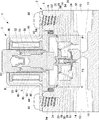
図1は、第1実施形態に係る電磁弁の構成を表す断面図である。図2は、調心機構を構成する板ばねを表す図である。図2(A)は正面図を示し、図2(B)は平面図を示している。図3は、図1のA部拡大図である。   FIG. 1 is a cross-sectional view illustrating the configuration of the electromagnetic valve according to the first embodiment. FIG. 2 is a diagram illustrating a leaf spring constituting the alignment mechanism. 2A shows a front view, and FIG. 2B shows a plan view. FIG. 3 is an enlarged view of a portion A in FIG.

図1に示すように、電磁弁1は、弁本体2とソレノイド3とを組み付けて構成される。電磁弁1は、常閉型の弁(非通電時に閉弁状態となる弁)であり、ソレノイド3への供給電流値に応じてその開度を比例的に変化させる比例弁として機能する。弁本体2は、ブロック状のボディ5を有し、そのボディ5の上端開口部を封止するようにソレノイド3が組み付けられている。ボディ5は、金属製の素材を切削加工して得られる。   As shown in FIG. 1, the electromagnetic valve 1 is configured by assembling a valve body 2 and a solenoid 3. The solenoid valve 1 is a normally closed valve (a valve that is closed when not energized), and functions as a proportional valve that proportionally changes its opening according to the current value supplied to the solenoid 3. The valve body 2 has a block-shaped body 5, and a solenoid 3 is assembled so as to seal the upper end opening of the body 5. The body 5 is obtained by cutting a metal material.

ボディ5の一側面には、上流側(供給源側)から反応ガス(水素ガス)を導入するための導入ポート10が設けられ、その反対側面には、下流側(燃料電池側)へ反応ガスを導出する導出ポート12が設けられている。導入ポート10と導出ポート12とをつなぐ流体通路の中途には弁孔14が設けられている。   An introduction port 10 for introducing a reaction gas (hydrogen gas) from the upstream side (supply source side) is provided on one side of the body 5, and the reaction gas is provided on the opposite side to the downstream side (fuel cell side). Is provided. A valve hole 14 is provided in the middle of the fluid passage connecting the inlet port 10 and the outlet port 12.

ボディ5の上部中央にはソレノイド3を取り付けるための取付孔16が設けられ、上方に開口している。ボディ5の上半部中央には、弁孔14の上流側に作動室18が画成されている。作動室18は、ソレノイド3の内部に連通している。作動室18には、弁孔14と対向するように弁体20,22が配設されている。弁体20は「第1弁体」として機能し、弁体22は「第2弁体」として機能する。   An attachment hole 16 for attaching the solenoid 3 is provided in the upper center of the body 5 and opens upward. A working chamber 18 is defined at the center of the upper half of the body 5 on the upstream side of the valve hole 14. The working chamber 18 communicates with the interior of the solenoid 3. Valve bodies 20 and 22 are disposed in the working chamber 18 so as to face the valve hole 14. The valve body 20 functions as a “first valve body”, and the valve body 22 functions as a “second valve body”.

導入ポート10および導出ポート12は、ボディ5の下部に開口する。導入ポート10の奥方に向けて連通路11が設けられ、導出ポート12の奥方に向けて連通路13が設けられている。連通路11,13と作動室18とは、隔壁19によって仕切られている。隔壁19の上面が作動室18の底面を構成する。   The introduction port 10 and the outlet port 12 open at the lower part of the body 5. A communication path 11 is provided toward the back of the introduction port 10, and a communication path 13 is provided toward the back of the lead-out port 12. The communication passages 11 and 13 and the working chamber 18 are partitioned by a partition wall 19. The upper surface of the partition wall 19 constitutes the bottom surface of the working chamber 18.

隔壁19の中央を軸線方向に貫通するように弁孔14が形成されている。弁孔14は小口径の通路からなる。弁孔14の上端開口部には弁座24が形成されている。隔壁19の上面には、弁孔14を中心とする円ボス状の支持部26が隆起している。支持部26は、半径方向内側に低くなる段差を有し、その段差の内側にリング状の弁座28が嵌合するように設けられている。弁座28は、ゴム等の弾性部材からなり、弁座24を同心状に取り囲む。支持部26の上段にはリング状のワッシャ30が固定されており、弁座28の周縁部を上方から押さえてその脱落を防止している。弁座24は「第1弁座」として機能し、弁座28は「第2弁座」として機能する。   A valve hole 14 is formed so as to penetrate the center of the partition wall 19 in the axial direction. The valve hole 14 is a small-diameter passage. A valve seat 24 is formed at the upper end opening of the valve hole 14. On the upper surface of the partition wall 19, a circular boss-like support portion 26 centering on the valve hole 14 is raised. The support portion 26 has a step that decreases inward in the radial direction, and is provided so that a ring-shaped valve seat 28 fits inside the step. The valve seat 28 is made of an elastic member such as rubber and surrounds the valve seat 24 concentrically. A ring-shaped washer 30 is fixed to the upper stage of the support portion 26, and the peripheral edge portion of the valve seat 28 is pressed from above to prevent its falling off. The valve seat 24 functions as a “first valve seat”, and the valve seat 28 functions as a “second valve seat”.

弁孔14は、ソレノイド3の軸線に沿って設けられ、連通路13を介して導出ポート12と連通している。隔壁19における支持部26の外側には、弁孔14と平行な連通孔32が設けられている。弁孔14は、作動室18,連通孔32および連通路11を介して導入ポート10と連通している。弁体20は、弁体22に同軸状に挿通され、軸線方向に摺動可能に支持されている。弁体20が弁座24に着脱することにより弁部を開閉する。弁体22は、有底段付円筒状をなし、下方に向けて外径が小さくなる形状を有する。弁体22の下端部が弁座28に着脱することによりシール部を開閉する。この同心状に配設された弁体20,22が、並列に作動する二段弁を構成する。この二段弁の構成および動作の詳細については後述する。   The valve hole 14 is provided along the axis of the solenoid 3 and communicates with the outlet port 12 via the communication path 13. A communication hole 32 parallel to the valve hole 14 is provided outside the support portion 26 in the partition wall 19. The valve hole 14 communicates with the introduction port 10 through the working chamber 18, the communication hole 32, and the communication path 11. The valve body 20 is coaxially inserted into the valve body 22 and is supported so as to be slidable in the axial direction. When the valve body 20 is attached to and detached from the valve seat 24, the valve portion is opened and closed. The valve body 22 has a bottomed stepped cylindrical shape and has a shape in which the outer diameter decreases toward the bottom. The lower end portion of the valve body 22 is attached to and detached from the valve seat 28 to open and close the seal portion. The concentric valve bodies 20 and 22 constitute a two-stage valve that operates in parallel. Details of the configuration and operation of this two-stage valve will be described later.

作動室18の中央を径方向に延在するように板ばね34が設けられている。板ばね34は、その外周部がボディ5に固定され、内周部が弁体22の上端部に接続されている。板ばね34は、弁体22を半径方向に支持し、弁体22の軸線方向の動作をガイドする「調心機構」として機能する。   A leaf spring 34 is provided so as to extend in the radial direction in the center of the working chamber 18. The leaf spring 34 has an outer peripheral portion fixed to the body 5 and an inner peripheral portion connected to the upper end portion of the valve body 22. The leaf spring 34 functions as an “alignment mechanism” that supports the valve body 22 in the radial direction and guides the operation of the valve body 22 in the axial direction.

図2(A)および(B)に示すように、板ばね34は、非磁性の金属板をプレス成形により図示の形状に打ち抜き、ばね性をもたせることにより得られる。板ばね34は、中央に挿通孔74を有する円板状の本体72と、本体72の外周の3箇所からそれぞれ延設された脚部76を有する。この3つの脚部76は、本体72の外周縁部から周方向(一方向)に延在し、それらの外接円が挿通孔74と同心円となるようにされている。また、3つの脚部76を本体72に対して片側(上方)に延在させることで、ばね性がもたせられている。なお、図1には便宜上、図2(B)のC−C断面が示されている。   As shown in FIGS. 2 (A) and 2 (B), the leaf spring 34 is obtained by punching a nonmagnetic metal plate into the shape shown in the drawing by press molding to have a spring property. The leaf spring 34 has a disc-shaped main body 72 having an insertion hole 74 in the center, and leg portions 76 respectively extending from three locations on the outer periphery of the main body 72. The three legs 76 extend from the outer peripheral edge of the main body 72 in the circumferential direction (one direction), and the circumscribed circles thereof are concentric with the insertion hole 74. Further, the three leg portions 76 are extended to one side (upward) with respect to the main body 72 to provide springiness. For the sake of convenience, FIG. 1 shows a CC cross section of FIG.

図1に戻り、隔壁19と弁体22との間には、弁体22を開弁方向に付勢するスプリング36(「第1付勢部材」として機能する)が介装されている。弁体22の底部と弁体20の上端部との間には、弁体20を弁体22の先端部から突出させる方向に付勢するスプリング38(「第3付勢部材」として機能する)が介装されている。   Returning to FIG. 1, a spring 36 (which functions as a “first urging member”) that urges the valve body 22 in the valve opening direction is interposed between the partition wall 19 and the valve body 22. Between the bottom of the valve body 22 and the upper end of the valve body 20, a spring 38 (functioning as a “third urging member”) that urges the valve body 20 in a direction in which the valve body 20 protrudes from the distal end portion of the valve body 22. Is intervening.

ソレノイド3は、円筒状のボビン40と、ボビン40に巻回された電磁コイル42と、電磁コイル42を取り囲むヨーク44と、ボビン40に挿通された非磁性のスリーブ45と、スリーブ45の上端部に固定された固定鉄心46と、スリーブ45の内方にて固定鉄心46と軸線方向に対向配置される可動鉄心48とを含む。スリーブ45は円筒状をなし、固定鉄心46は有底円筒状をなしている。固定鉄心46の下端部をスリーブ45の上端部に挿通した状態で両者の接続部に外周溶接を施すことにより、両者が同軸状に固定されている。   The solenoid 3 includes a cylindrical bobbin 40, an electromagnetic coil 42 wound around the bobbin 40, a yoke 44 surrounding the electromagnetic coil 42, a nonmagnetic sleeve 45 inserted through the bobbin 40, and an upper end portion of the sleeve 45. And a movable iron core 48 disposed axially opposite to the stationary iron core 46 inside the sleeve 45. The sleeve 45 has a cylindrical shape, and the fixed iron core 46 has a bottomed cylindrical shape. Both ends are fixed coaxially by performing outer periphery welding on the connecting portion in a state where the lower end portion of the fixed iron core 46 is inserted into the upper end portion of the sleeve 45.

固定鉄心46の中央部には、下方に向けて開口する凹部50が形成されている。凹部50は、下方に向けて段階的に拡径する段付円孔状をなし、非磁性のガイド部材52が下方に向けて立設されている。ガイド部材52は、樹脂材の射出成形により得られ、下方に向けて段階的に小径化する有底段付円筒状をなす。ガイド部材52は、その大径部が凹部50に圧入されており、小径部が可動鉄心48に向けて延出している。ガイド部材52を樹脂材による中空構造とすることで、その凹部50への圧入を容易にしている。   A concave portion 50 that opens downward is formed at the center of the fixed iron core 46. The concave portion 50 has a stepped circular hole shape whose diameter gradually increases downward, and a nonmagnetic guide member 52 is erected downward. The guide member 52 is obtained by injection molding of a resin material and has a bottomed stepped cylindrical shape whose diameter is gradually reduced downward. The guide member 52 has a large diameter portion press-fitted into the recess 50 and a small diameter portion extending toward the movable iron core 48. Since the guide member 52 has a hollow structure made of a resin material, the press-fitting into the recess 50 is facilitated.

可動鉄心48は、上方に向けて段階的に小径化される段付円柱状をなし、その下面中央に作動連結部54が突設されている。可動鉄心48は、作動連結部54を介して弁体22と接続される。可動鉄心48の外周面とスリーブ45の内周面との間に比較的大きな空間Sが形成され、可動鉄心48の側面を介した無用な磁気漏洩が防止されている。すなわち、空間Sは「磁気漏洩防止空間」として機能する。   The movable iron core 48 has a stepped columnar shape whose diameter is gradually reduced upward, and an operation connecting portion 54 projects from the center of the lower surface thereof. The movable iron core 48 is connected to the valve body 22 via the operation connecting portion 54. A relatively large space S is formed between the outer peripheral surface of the movable iron core 48 and the inner peripheral surface of the sleeve 45, and unnecessary magnetic leakage through the side surface of the movable iron core 48 is prevented. That is, the space S functions as a “magnetic leakage prevention space”.

可動鉄心48の上端部が円筒状の筒状部56となっており、ガイド部材52の下端部が挿通されている。ガイド部材52は、筒状部56を軸線方向に摺動可能に支持する滑り軸受として機能する。固定鉄心46と可動鉄心48との間には、可動鉄心48を固定鉄心46から離間する方向に付勢するスプリング58(「第2付勢部材」として機能する)が介装されている。スプリング58は、非磁性のステンレス鋼からなり、可動鉄心48の小径部を挿通する形で空間Sに配置されている。作動連結部54は、円錐状(テーパ状)をなし、その先端が弁体22の上面中央に点接触態様で接続される。   The upper end portion of the movable iron core 48 is a cylindrical tubular portion 56, and the lower end portion of the guide member 52 is inserted. The guide member 52 functions as a sliding bearing that supports the cylindrical portion 56 so as to be slidable in the axial direction. A spring 58 (functioning as a “second urging member”) that urges the movable core 48 in a direction away from the fixed core 46 is interposed between the fixed core 46 and the movable core 48. The spring 58 is made of nonmagnetic stainless steel, and is disposed in the space S so as to be inserted through the small diameter portion of the movable iron core 48. The operation connecting portion 54 has a conical shape (tapered shape), and the tip thereof is connected to the center of the upper surface of the valve body 22 in a point contact manner.

ヨーク44は、ボビン40を下方から支持する第1ヨーク60と、ソレノイド3の構成部品を上方から囲う第2ヨーク62とを組み付けて構成される。第1ヨーク60は有底円筒状をなし、その開口端を下にして取付孔16に嵌合されている。第1ヨーク60と取付孔16との間には、シール用のOリング64が介装されている。第1ヨーク60の底部中央を貫通するように段付孔63が設けられている。段付孔63の上段の大径部にスリーブ45の下端部が圧入されている。すなわち、固定鉄心46,スリーブ45および第1ヨーク60は、同軸状に気密に接合されている。可動鉄心48の下半部は、段付孔63を貫通して作動室18に延出する。第1ヨーク60の下方に作動室18が形成されている。   The yoke 44 is configured by assembling a first yoke 60 that supports the bobbin 40 from below and a second yoke 62 that surrounds the components of the solenoid 3 from above. The first yoke 60 has a bottomed cylindrical shape, and is fitted in the mounting hole 16 with its open end facing down. A sealing O-ring 64 is interposed between the first yoke 60 and the mounting hole 16. A stepped hole 63 is provided so as to penetrate the center of the bottom of the first yoke 60. The lower end portion of the sleeve 45 is press-fitted into the upper large diameter portion of the stepped hole 63. That is, the fixed iron core 46, the sleeve 45, and the first yoke 60 are coaxially and airtightly joined. The lower half of the movable core 48 extends through the stepped hole 63 to the working chamber 18. A working chamber 18 is formed below the first yoke 60.

第2ヨーク62は、板状の磁性体を凸状に曲げ成形して得られたものであり、その両端部がそれぞれボディ5の上面にボルト66を介して固定されている。これにより、第2ヨーク62の下面が第1ヨーク60の上面を押さえる形となり、第1ヨーク60の脱落が防止されている。また、第2ヨーク62の上部中央には貫通孔68が設けられ、固定鉄心46の上部を貫通させている。第2ヨーク62の上部が上方からボビン40の上面を押さえる形となり、ソレノイド3の構成部品の脱落が防止されている。   The second yoke 62 is obtained by bending a plate-like magnetic body into a convex shape, and both end portions thereof are fixed to the upper surface of the body 5 via bolts 66, respectively. As a result, the lower surface of the second yoke 62 presses the upper surface of the first yoke 60, and the first yoke 60 is prevented from falling off. Further, a through hole 68 is provided in the upper center of the second yoke 62 and penetrates the upper portion of the fixed iron core 46. The upper part of the second yoke 62 presses the upper surface of the bobbin 40 from above, and the components of the solenoid 3 are prevented from falling off.

図3に示すように、弁体22は、段付円筒状の本体80と、その本体80の上端開口部を閉止する円板状の支持部材82とを含む。支持部材82は本体80に圧入されている。それにより、弁体22の上端部が気密にシールされ、弁孔14に向けて開口する内部空間S2が形成される。   As shown in FIG. 3, the valve body 22 includes a stepped cylindrical main body 80 and a disk-shaped support member 82 that closes the upper end opening of the main body 80. The support member 82 is press-fitted into the main body 80. Thereby, the upper end of the valve body 22 is hermetically sealed, and an internal space S2 that opens toward the valve hole 14 is formed.

本体80の下端は縮径されており、その内周面が弁体20を摺動可能に支持する支持部84となっている。本体80の上部には半径方向外向きに延出するフランジ部86が設けられている。スプリング36は、上方に向けて小径化するテーパスプリングからなり、その上端がフランジ部86に連結されている。板ばね34の挿通孔74に弁体22の上端部が圧入されている。板ばね34は、その本体72の下面がフランジ部86の上面に当接した状態を維持しつつ、弁体22と一体に変位する。板ばね34は、3つの脚部76の先端がそれぞれボディ5と第1ヨーク60との間に挟持され、それにより半径方向に延在しつつ軸線方向に弾性変形可能とされている。板ばね34が、複数の脚部76により中央の本体72を支持する形状であるため、作動室18に導入された流体は、これらの脚部76の間を通過してソレノイド3の内部(空間S等)にも導かれる。   The lower end of the main body 80 has a reduced diameter, and an inner peripheral surface thereof serves as a support portion 84 that supports the valve body 20 so as to be slidable. A flange portion 86 extending outward in the radial direction is provided on the upper portion of the main body 80. The spring 36 is a taper spring whose diameter decreases upward, and its upper end is connected to the flange portion 86. The upper end portion of the valve body 22 is press-fitted into the insertion hole 74 of the leaf spring 34. The leaf spring 34 is displaced integrally with the valve body 22 while maintaining the state in which the lower surface of the main body 72 is in contact with the upper surface of the flange portion 86. In the leaf spring 34, the tips of the three leg portions 76 are sandwiched between the body 5 and the first yoke 60, respectively, so that they can be elastically deformed in the axial direction while extending in the radial direction. Since the leaf spring 34 is shaped to support the central main body 72 by a plurality of legs 76, the fluid introduced into the working chamber 18 passes between the legs 76 and passes through the interior of the solenoid 3 (space). S etc.).

支持部材82の上面中央には逆円錐状(テーパ状、すり鉢状)の凹部88が設けられ、作動連結部54を受け入れ可能とされている。凹部88は、軸線に対するテーパ角が作動連結部54のそれよりも大きい。このため、作動連結部54と支持部材82(つまり弁体22)とが互いの軸線上で点接触態様にて接続される。支持部材82の下面中央には凸部90が設けられ、スプリング38の軸芯となっている。   An inverted conical (tapered, mortar-shaped) concave portion 88 is provided in the center of the upper surface of the support member 82 so that the operation connecting portion 54 can be received. The concave portion 88 has a taper angle with respect to the axis that is larger than that of the operation connecting portion 54. For this reason, the action | operation connection part 54 and the supporting member 82 (namely, valve body 22) are connected in a point contact aspect on the mutual axis. A convex portion 90 is provided at the center of the lower surface of the support member 82 and serves as the axis of the spring 38.

弁体20は、ニードル状をなし、長尺状の本体92と、本体92の先端側に設けられた弁形成部94と、本体92の後端側にて半径方向に突出するフランジ部96とを有する。弁形成部94は、先端に向けて断面が小さくなるテーパ形状を有する。弁形成部94が弁孔14に挿入されつつ弁座24に着座する。フランジ部96は「係止部」として機能し、その下面が支持部84の上面に係止されることで、弁体20の弁体22からの脱落が防止される。フランジ部96と支持部材82との間にスプリング38が介装される。弁体22は、弁体20を内部空間S2に部分的に収容しつつ、軸線方向に変位可能に支持する。   The valve body 20 has a needle-like shape, a long main body 92, a valve forming portion 94 provided on the front end side of the main body 92, and a flange portion 96 protruding in the radial direction on the rear end side of the main body 92. Have The valve forming portion 94 has a tapered shape whose cross section decreases toward the tip. The valve forming portion 94 is seated on the valve seat 24 while being inserted into the valve hole 14. The flange portion 96 functions as a “locking portion”, and the lower surface of the flange portion 96 is locked to the upper surface of the support portion 84, thereby preventing the valve body 20 from dropping from the valve body 22. A spring 38 is interposed between the flange portion 96 and the support member 82. The valve body 22 supports the valve body 20 so as to be displaceable in the axial direction while partially accommodating the valve body 20 in the internal space S2.

図1に戻り、以上のような構成により、可動鉄心48,弁体22および弁体20が同軸状に作動連結される。作動連結部54が弁体22に点接触態様で接続される一方、ガイド部材52が筒状部56に挿通されることにより、可動鉄心48は、一端側が点支持され、他端側が円筒支持(摺動可能に支持)される態様で軸線方向に変位する。   Returning to FIG. 1, the movable iron core 48, the valve body 22, and the valve body 20 are operatively connected coaxially with the above-described configuration. While the operation connecting portion 54 is connected to the valve body 22 in a point contact manner, the guide member 52 is inserted into the tubular portion 56, whereby the movable iron core 48 is point-supported at one end side and cylindrically supported at the other end side ( It is displaced in the axial direction in such a manner that it is slidably supported.

次に、電磁弁1の動作について説明する。
図4は、電磁弁の動作を表す図であり、図1のB部拡大図に対応する。図4(A)および(B)は、ソレノイド3への通電開始後の開弁過程を示す。既に説明した図1は、ソレノイド3の非通電状態を示す。電磁弁1への通電制御は、PWM制御(Pulse Width Modulation)によりなされる。このPWM制御は、図示しない制御部により実行される。この制御部は、指定したデューティ比のパルス信号を出力するPWM出力部を有するが、その構成自体には公知のものが採用されるため、詳細な説明を省略する。
Next, the operation of the electromagnetic valve 1 will be described.
FIG. 4 is a diagram illustrating the operation of the electromagnetic valve, and corresponds to an enlarged view of a portion B in FIG. 4A and 4B show the valve opening process after the energization of the solenoid 3 is started. FIG. 1 which has already been described shows a non-energized state of the solenoid 3. The energization control to the solenoid valve 1 is performed by PWM control (Pulse Width Modulation). This PWM control is executed by a control unit (not shown). The control unit includes a PWM output unit that outputs a pulse signal having a designated duty ratio. However, since the configuration itself is employed, detailed description thereof is omitted.

図1に示すように、ソレノイド3がオフの状態(非通電状態)では、固定鉄心46と可動鉄心48との間に吸引力が作用しない。このため、スプリング58の付勢力により可動鉄心48が下方(閉弁方向)に付勢される。この付勢力が、作動連結部54を介して弁体22に伝達される。その結果、弁体22が弁座28に着座してシール部を閉じる。また、スプリング38の付勢力により弁体20が弁座24に着座して弁部を閉じる。このとき、弁体22が弁座28に対して弾性的に押し付けられる。また、弁体22の内部空間S2の圧力が弁部の下流側圧力P2と等しくなり、弁体22には上流側圧力P1と下流側圧力P2との差圧(P1−P2)がシール部の閉方向に作用する。このため、シール部のシール機能が良好に維持される。   As shown in FIG. 1, when the solenoid 3 is off (non-energized state), no attractive force acts between the fixed iron core 46 and the movable iron core 48. For this reason, the movable iron core 48 is urged downward (in the valve closing direction) by the urging force of the spring 58. This urging force is transmitted to the valve body 22 via the operation connecting portion 54. As a result, the valve body 22 sits on the valve seat 28 and closes the seal portion. Further, the valve body 20 is seated on the valve seat 24 by the urging force of the spring 38 to close the valve portion. At this time, the valve body 22 is elastically pressed against the valve seat 28. Further, the pressure in the internal space S2 of the valve body 22 becomes equal to the downstream pressure P2 of the valve portion, and the valve body 22 has a differential pressure (P1-P2) between the upstream pressure P1 and the downstream pressure P2 of the seal portion. Acts in the closing direction. For this reason, the sealing function of a seal part is maintained favorable.

一方、弁体20が弁座24から受ける反力によりスプリング38が押し縮められ、フランジ部96が支持部84から離間する。その結果、弁体20と弁体22との作動連結が解除される。それにより、閉弁時に弁体20に過大な負荷が作用することが防止される。   On the other hand, the spring 38 is pressed and contracted by the reaction force received by the valve body 20 from the valve seat 24, and the flange portion 96 is separated from the support portion 84. As a result, the operation connection between the valve body 20 and the valve body 22 is released. This prevents an excessive load from acting on the valve body 20 when the valve is closed.

ソレノイド3がオン(通電状態)にされると、固定鉄心46と可動鉄心48との間に吸引力が作用する。ソレノイド3への供給電流値を高めていくと、まず図4(A)に示すように、弁体22が開弁作動を開始し、弁部が閉じた状態でシール部が開放される。すなわち、供給電流値が所定値以下のとき、弁体22が弁座28から離脱してシール部を開放するが、弁体20は弁座24に押し付けられたままであり、弁部は閉弁状態を保つ。このとき、弁体22のリフト量が大きくなるにしたがってその受圧面積(下流側圧力P2を受圧する面積)は小さくなる。それとともに内部空間S2の圧力が上流側圧力P1に近づき、弁体22に作用する差圧(P1−P2)が小さくなる。このため、シール部のシール機能は徐々に弱められる。   When the solenoid 3 is turned on (energized state), a suction force acts between the fixed iron core 46 and the movable iron core 48. When the supply current value to the solenoid 3 is increased, first, as shown in FIG. 4A, the valve body 22 starts the valve opening operation, and the seal portion is opened with the valve portion closed. That is, when the supply current value is less than or equal to a predetermined value, the valve body 22 is detached from the valve seat 28 and opens the seal portion, but the valve body 20 remains pressed against the valve seat 24 and the valve portion is in a closed state. Keep. At this time, as the lift amount of the valve body 22 increases, the pressure receiving area (area receiving the downstream pressure P2) decreases. At the same time, the pressure in the internal space S2 approaches the upstream pressure P1, and the differential pressure (P1-P2) acting on the valve body 22 decreases. For this reason, the sealing function of a seal part is weakened gradually.

そして、供給電流値が所定値を超えることでシール部の開度が所定開度に達すると、弁体22が下流側圧力P2を実質的に受圧しなくなる。本実施形態では、このとき弁体20が速やかに開弁作動を開始するように、スプリング36,58の荷重設定がなされている。このとき、図4(B)に示すように、支持部84がフランジ部96に連結される。それにより、弁体20が弁体22によって引き上げられるようにして開弁方向に動作する。ソレノイド3への供給電流値に応じて、弁部の開度が比例的に制御される。これにより、導入ポート10から導入された反応ガスが弁部を通過し、流量を調整された状態で導出ポート12から導出される。   When the supply current value exceeds a predetermined value and the opening of the seal portion reaches the predetermined opening, the valve body 22 does not substantially receive the downstream pressure P2. In the present embodiment, the loads of the springs 36 and 58 are set so that the valve body 20 immediately starts the valve opening operation at this time. At this time, the support portion 84 is connected to the flange portion 96 as shown in FIG. Thereby, the valve body 20 is lifted by the valve body 22 and operates in the valve opening direction. In accordance with the supply current value to the solenoid 3, the opening degree of the valve portion is proportionally controlled. As a result, the reaction gas introduced from the introduction port 10 passes through the valve portion and is led out from the lead-out port 12 with the flow rate adjusted.

このように、開弁作動においては、弁体22が弁座28から離脱してシール部を開いた後、弁体20が弁座24から離脱して弁部を開き、弁体20と弁体22とが一体変位することで弁部の開度が調整される。この開弁過程において、図中太い二点鎖線にて示すような磁気回路が形成される。すなわち、弁部の開度が所定値以上となったときに、可動鉄心48と固定鉄心46とが径方向にオーバラップし、弁開度が大きくなるにつれてそのオーバラップ量が大きくなる。このようにして可動鉄心48と固定鉄心46との間の磁気通路を半径方向にずらすことで、両者が接近してもその位置関係によって磁気吸引力が急激に増大することを防止できる。これにより、供給電流値の変化に対して吸引力を細かく変化させることができ、比例制御を精密に行えるようにしている。   Thus, in the valve opening operation, after the valve body 22 is detached from the valve seat 28 and the seal portion is opened, the valve body 20 is detached from the valve seat 24 and the valve portion is opened, and the valve body 20 and the valve body are opened. The opening degree of the valve part is adjusted by integrally displacing 22. In this valve opening process, a magnetic circuit as shown by a thick two-dot chain line in the figure is formed. That is, when the opening degree of the valve portion exceeds a predetermined value, the movable iron core 48 and the fixed iron core 46 overlap in the radial direction, and the amount of overlap increases as the valve opening degree increases. Thus, by shifting the magnetic path between the movable iron core 48 and the fixed iron core 46 in the radial direction, it is possible to prevent the magnetic attraction force from rapidly increasing due to the positional relationship even if both approach each other. Thereby, the attractive force can be finely changed with respect to the change in the supply current value, and the proportional control can be performed precisely.

なお、閉弁作動においては上記と逆の動作を経ることになる。すなわち、弁体20が弁座24に着座して弁部を閉じた後、弁体22が弁座28に着座してシール部を閉じる。このような電磁弁1の開閉動作過程において、板ばね34により弁体22が軸線に沿って安定にガイドされる。すなわち、板ばね34の外周縁がボディ5にしっかりと固定されているため、板ばね34の変形過程でその軸線が変化することが防止又は抑制される。このため、弁体22は、板ばね34の中央に支持される形で軸線に沿って安定にガイドされる。   In the valve closing operation, the reverse operation is performed. That is, after the valve body 20 is seated on the valve seat 24 and the valve portion is closed, the valve body 22 is seated on the valve seat 28 and the seal portion is closed. During the opening / closing operation of the electromagnetic valve 1, the valve element 22 is stably guided along the axis by the leaf spring 34. That is, since the outer peripheral edge of the leaf spring 34 is firmly fixed to the body 5, it is prevented or suppressed from changing its axis during the deformation process of the leaf spring 34. Therefore, the valve body 22 is stably guided along the axis while being supported at the center of the leaf spring 34.

このように弁体22が安定に動作するため、これと同軸状に連結された可動鉄心48および弁体20も軸線方向に安定に動作するようになる。また、可動鉄心48については、一端が点支持、他端が円筒支持される特殊な構造を有する。このため、仮に磁気吸引力のバランスが崩れるなどして可動鉄心48が弁体22の軸線に対して傾いたとしても、点支持側の弁体22に与える影響は少ない。その結果、弁体22は、その軸線に沿った安定した動作を維持することができる。   Since the valve body 22 operates stably in this way, the movable iron core 48 and the valve body 20 connected coaxially thereto also operate stably in the axial direction. The movable iron core 48 has a special structure in which one end is point-supported and the other end is cylindrically supported. For this reason, even if the movable iron core 48 is tilted with respect to the axis of the valve body 22 due to, for example, the balance of the magnetic attractive force being lost, the influence on the point support side valve body 22 is small. As a result, the valve body 22 can maintain a stable operation along its axis.

図5は、弁ストロークと弁開度および受圧力との関係を表す図である。同図の横軸はシール部の弁ストロークを示し、縦軸は各弁の弁開度および受圧力を示す。ここで、「弁ストローク」は弁体22の弁座28からのリフト量を意味する。「弁開度」は弁部およびシール部の開口面積を意味し、「受圧力」は弁体20,22が流体から受ける差圧を意味する。図中太線がシール部に関する結果を示し、細線が弁部に関する結果を示す。また、実線が弁開度を示し、破線が受圧力を示す。   FIG. 5 is a diagram illustrating the relationship between the valve stroke, the valve opening degree, and the receiving pressure. In the figure, the horizontal axis indicates the valve stroke of the seal portion, and the vertical axis indicates the valve opening and receiving pressure of each valve. Here, the “valve stroke” means the lift amount of the valve body 22 from the valve seat 28. “Valve opening” means the opening area of the valve part and the seal part, and “received pressure” means the differential pressure that the valve bodies 20, 22 receive from the fluid. In the figure, the thick line indicates the result regarding the seal portion, and the thin line indicates the result regarding the valve portion. Moreover, a continuous line shows a valve opening degree and a broken line shows receiving pressure.

同図によれば、電磁弁1の完全閉状態(ソレノイド3がオフの状態)において、弁部およびシール部がともに閉状態となり、各弁体の受圧力(つまり差圧(P1−P2))は最大となる。ここで、受圧面積の関係から、弁体22の受圧力のほうが、弁体20のそれよりも大きい。   According to the figure, when the solenoid valve 1 is completely closed (solenoid 3 is off), both the valve portion and the seal portion are closed, and the pressure received by each valve body (that is, differential pressure (P1-P2)). Is the maximum. Here, from the relationship of the pressure receiving area, the pressure received by the valve body 22 is larger than that of the valve body 20.

ソレノイド3がオンにされると、電磁弁1が開弁作動を開始する。このとき、まずシール部が開き、その開度が大きくなるとともに弁体22の受圧力が減少する。弁部の開度および受圧力は一定に保持される。そして、弁ストロークがaになると、弁体22の受圧力がなくなり、その後、速やかに弁部が開き始める。弁部の開度が大きくなるとともに弁体20の受圧力は減少する。そして、弁ストロークがbになると、弁体20の受圧力もなくなり、その後、ソレノイド3への供給電流値が高まるとともに弁ストロークが増大し、弁部の開度が大きくなる。それにより、弁開度を比例的に制御することができる。   When the solenoid 3 is turned on, the electromagnetic valve 1 starts to open. At this time, the seal portion is first opened, the opening degree thereof increases, and the pressure received by the valve body 22 decreases. The opening degree and the receiving pressure of the valve part are kept constant. When the valve stroke becomes a, the pressure received by the valve body 22 is lost, and then the valve portion begins to open quickly. As the opening of the valve portion increases, the pressure received by the valve body 20 decreases. When the valve stroke becomes b, the receiving pressure of the valve body 20 is also lost, and thereafter, the supply current value to the solenoid 3 increases, the valve stroke increases, and the opening of the valve portion increases. Thereby, the valve opening degree can be controlled proportionally.

ここで、電磁弁1の制御特性は弁部の作動に依存するところ、弁部とシール部の双方が開弁状態のときに安定する。このため、制御仕様の最大開度が図中二点鎖線にて示す値であった場合、電磁弁1による流量制御範囲は、弁部の開弁開始以降の図示の範囲となる。本実施形態では、開弁作動においてはシール部を開いた後に弁部を開き、閉弁作動においては弁部を閉じた後にシール部を閉じる構成とした。このため、この逆の作動をする制御弁と比較して流量制御範囲を大きくとることができる。また、制御の安定性の観点からも、弁体20の受圧力がなくなる弁ストロークbを、弁体22の受圧力がなくなる弁ストロークaよりも大きくするのが好ましい。それにより、差圧の変動によるシール部の自開および自閉動作を防止又は抑制でき、弁部の開度を安定に維持できるためである。   Here, the control characteristic of the electromagnetic valve 1 depends on the operation of the valve portion, and is stable when both the valve portion and the seal portion are in the valve open state. For this reason, when the maximum opening degree of the control specification is a value indicated by a two-dot chain line in the figure, the flow rate control range by the electromagnetic valve 1 becomes the range shown in the figure after the valve opening start of the valve portion. In the present embodiment, the valve portion is opened after the seal portion is opened in the valve opening operation, and the seal portion is closed after the valve portion is closed in the valve closing operation. For this reason, the flow rate control range can be increased as compared with a control valve that operates in the opposite direction. Also from the viewpoint of control stability, it is preferable that the valve stroke b at which the receiving pressure of the valve body 20 disappears is larger than the valve stroke a at which the receiving pressure of the valve body 22 disappears. Thereby, the self-opening and self-closing operations of the seal part due to the fluctuation of the differential pressure can be prevented or suppressed, and the opening degree of the valve part can be stably maintained.

以上に説明したように、本実施形態では、可動鉄心48と弁体22とが別体とされ、作動連結可能に構成されている。このため、可動鉄心48と弁体22とが点接触状態となる。さらに、弁体20と弁体22とが別体とされ、弁体22が弁体20に弾性的に支持されている。このため、仮に可動鉄心48に軸ずれや傾きが生じたとしても、弁体22ひいては弁体20に与える影響は少ない。そのため、開弁時における弁体20の作動を安定に保ち、比例制御特性を良好に維持することができる。また、閉弁時における弁体22によるシール性能を高めることができる。   As described above, in the present embodiment, the movable iron core 48 and the valve body 22 are separated and configured to be operatively connectable. For this reason, the movable iron core 48 and the valve body 22 are in a point contact state. Further, the valve body 20 and the valve body 22 are separated from each other, and the valve body 22 is elastically supported by the valve body 20. For this reason, even if an axis deviation or inclination occurs in the movable iron core 48, the influence on the valve body 22 and the valve body 20 is small. Therefore, the operation of the valve body 20 when the valve is opened can be kept stable, and the proportional control characteristics can be maintained well. Moreover, the sealing performance by the valve body 22 at the time of valve closing can be improved.

また、ガイド部材52により可動鉄心48の一端の内周を支持する構成としたことにより、外周を支持する構成よりも加工精度を向上させることができる。可動鉄心48に軸ずれや傾きが弁体の作動に影響し難いことにより、逆に可動鉄心48の加工精度を緩和することも可能となる。   In addition, since the guide member 52 is configured to support the inner periphery of one end of the movable iron core 48, the processing accuracy can be improved as compared to the configuration of supporting the outer periphery. Since the axial deviation and inclination of the movable iron core 48 hardly affect the operation of the valve body, the machining accuracy of the movable iron core 48 can be relaxed.

[第2実施形態]
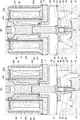
本実施形態の電磁弁は、第2弁体および調心機構の構成が第1実施形態と相異する。以下では第1実施形態との相異点を中心に説明し、第1実施形態と同様の構成については同一の符号を付す等してその説明を省略する。図6は、第2実施形態に係る電磁弁の構成を表す部分拡大断面図であり、第1実施形態の図3に対応する。
[Second Embodiment]
The electromagnetic valve of the present embodiment is different from the first embodiment in the configuration of the second valve body and the alignment mechanism. Below, it demonstrates centering on difference with 1st Embodiment, about the structure similar to 1st Embodiment, the same code | symbol is attached | subjected and the description is abbreviate | omitted. FIG. 6 is a partially enlarged cross-sectional view showing the configuration of the solenoid valve according to the second embodiment, and corresponds to FIG. 3 of the first embodiment.

電磁弁201は、第1実施形態のような板ばね34は設けられていない。隔壁19から円ボス状の支持部226が大きく突設され、弁体222(「第2弁体」として機能する)が軸線方向に支持されている。弁体222は、支持部226に挿通される大径の本体280を有する。本体280の上部にフランジ部86が設けられ、下部に支持部84が設けられている。支持部226と弁孔14とが同軸状であることから、弁体222は、軸線に沿って摺動可能に支持されている。すなわち、この支持部226によって弁体222をガイドする機構が、「調心機構」を構成する。また、本体280の外周面が部分的に切り欠かれ、弁孔14と作動室18とを連通させる連通路282が形成されている。このような構成によっても第1実施形態と同様の効果を得ることができる。   The solenoid valve 201 is not provided with the leaf spring 34 as in the first embodiment. A circular boss-shaped support portion 226 protrudes from the partition wall 19, and a valve body 222 (functioning as a “second valve body”) is supported in the axial direction. The valve body 222 has a large-diameter main body 280 inserted through the support portion 226. A flange portion 86 is provided on the upper portion of the main body 280, and a support portion 84 is provided on the lower portion. Since the support part 226 and the valve hole 14 are coaxial, the valve body 222 is slidably supported along the axis. That is, the mechanism that guides the valve body 222 by the support portion 226 constitutes an “alignment mechanism”. In addition, the outer peripheral surface of the main body 280 is partially cut away, and a communication passage 282 that connects the valve hole 14 and the working chamber 18 is formed. Even with such a configuration, the same effect as in the first embodiment can be obtained.

[第3実施形態]
本実施形態の電磁弁は、常開型の弁(非通電時に全開状態となる弁)である点で第1実施形態と相異する。以下では第1実施形態との相異点を中心に説明し、第1実施形態と同様の構成については同一の符号を付す等してその説明を省略する。図7は、第3実施形態に係る電磁弁の構成を表す断面図である。
[Third Embodiment]
The solenoid valve of the present embodiment is different from the first embodiment in that it is a normally open valve (a valve that is fully opened when not energized). Below, it demonstrates centering on difference with 1st Embodiment, about the structure similar to 1st Embodiment, the same code | symbol is attached | subjected and the description is abbreviate | omitted. FIG. 7 is a cross-sectional view illustrating a configuration of a solenoid valve according to the third embodiment.

電磁弁301は、弁本体2とソレノイド303とを組み付けて構成される。ソレノイド303は、ボビン40に挿通された有底円筒状のスリーブ345と、第1ヨーク60と一体に設けられた固定鉄心346と、スリーブ345の内方にて固定鉄心346と軸線方向に対向配置される可動鉄心348とを含む。可動鉄心348と固定鉄心346との上下の位置関係が、第1実施形態とは逆となっている。スリーブ345は、第2ヨーク62を貫通し、その底部が上方に露出し、下端部が固定鉄心346に組み付けられている。   The electromagnetic valve 301 is configured by assembling the valve body 2 and a solenoid 303. The solenoid 303 has a bottomed cylindrical sleeve 345 inserted through the bobbin 40, a fixed iron core 346 provided integrally with the first yoke 60, and an axially opposed arrangement with the fixed iron core 346 inside the sleeve 345. Movable iron core 348. The vertical positional relationship between the movable iron core 348 and the fixed iron core 346 is opposite to that in the first embodiment. The sleeve 345 passes through the second yoke 62, the bottom thereof is exposed upward, and the lower end is assembled to the fixed iron core 346.

スリーブ345の底部には、樹脂製のガイド部材352が固定されている。ガイド部材352は、円板状の本体310と、本体310の下面中央に突設されたガイド部312とを有する。可動鉄心348の上端部が円筒状の筒状部356となっており、ガイド部312が挿通されている。ガイド部312は、筒状部356を軸線方向に摺動可能に支持する滑り軸受として機能する。   A resin guide member 352 is fixed to the bottom of the sleeve 345. The guide member 352 includes a disk-shaped main body 310 and a guide portion 312 that protrudes from the center of the lower surface of the main body 310. The upper end portion of the movable iron core 348 is a cylindrical tubular portion 356, and the guide portion 312 is inserted therethrough. The guide portion 312 functions as a sliding bearing that supports the cylindrical portion 356 so as to be slidable in the axial direction.

可動鉄心348は、下方に向けて段階的に小径化される段付円柱状をなし、その下部に連結部材354が同軸状に固定されている。可動鉄心348の下面中央には円孔状の凹部360が形成されている。連結部材354は、ロッド状をなし、その上端部が凹部360に圧入されている。連結部材354の下端部が円錐状(テーパ状)をなし、その先端が弁体22の上面中央に点接触態様で接続される。すなわち、連結部材354は「作動連結部」として機能する。   The movable iron core 348 has a stepped columnar shape whose diameter is gradually reduced downward, and a connecting member 354 is coaxially fixed to the lower portion thereof. A circular recess 360 is formed in the center of the lower surface of the movable iron core 348. The connecting member 354 has a rod shape, and its upper end is press-fitted into the recess 360. The lower end portion of the connecting member 354 has a conical shape (tapered shape), and the tip thereof is connected to the center of the upper surface of the valve body 22 in a point contact manner. That is, the connecting member 354 functions as an “operation connecting portion”.

可動鉄心348の外周面とスリーブ345の内周面との間には、比較的大きな空間Sが形成されている。空間Sは「磁気漏洩防止空間」として機能する。   A relatively large space S is formed between the outer peripheral surface of the movable iron core 348 and the inner peripheral surface of the sleeve 345. The space S functions as a “magnetic leakage prevention space”.

次に、電磁弁301の動作について説明する。
図8は、電磁弁の動作を表す図であり、ソレノイド303へ通電がなされたときの状態を示す。図8(A)および(B)は、閉弁過程の動作を示す。既に説明した図7は、ソレノイド303の非通電状態を示す。
Next, the operation of the electromagnetic valve 301 will be described.
FIG. 8 is a diagram showing the operation of the solenoid valve, and shows a state when the solenoid 303 is energized. 8A and 8B show the operation of the valve closing process. FIG. 7 which has already been described shows a non-energized state of the solenoid 303.

図7に示すように、ソレノイド303がオフの状態では、固定鉄心346と可動鉄心348との間に吸引力が作用しない。このため、スプリング58の付勢力により可動鉄心348が上方(開弁方向)に付勢される。可動鉄心348は、その上端面がガイド部材352に係止されることで、その上方への変位が規制される。このとき、スプリング36の付勢力によって弁体22が押し上げられ、シール部が全開状態となる。弁体22により弁体20も引き上げられるため、弁部も全開状態となる。   As shown in FIG. 7, when the solenoid 303 is off, no attractive force acts between the fixed iron core 346 and the movable iron core 348. For this reason, the movable iron core 348 is biased upward (in the valve opening direction) by the biasing force of the spring 58. The upper end surface of the movable iron core 348 is locked to the guide member 352, so that the upward displacement thereof is restricted. At this time, the valve body 22 is pushed up by the urging force of the spring 36, and the seal portion is fully opened. Since the valve body 20 is also pulled up by the valve body 22, the valve portion is also fully opened.

ソレノイド303がオンにされると、固定鉄心346と可動鉄心348との間に吸引力が作用する。ソレノイド303への供給電流値を高めていくと、まず図8(A)に示すように、弁体20が閉弁作動を開始し、やがて弁体20が弁座24に着座して弁部を閉じる。この過程において、ソレノイド303への供給電流値に応じて、弁部の開度が比例的に制御される。供給電流値が所定値を超えるまでは、シール部は開放された状態を保つ。   When the solenoid 303 is turned on, a suction force acts between the fixed iron core 346 and the movable iron core 348. When the supply current value to the solenoid 303 is increased, first, as shown in FIG. 8A, the valve body 20 starts the valve closing operation, and eventually the valve body 20 is seated on the valve seat 24 and the valve portion is moved. close up. In this process, the opening degree of the valve portion is proportionally controlled in accordance with the value of the current supplied to the solenoid 303. Until the supply current value exceeds a predetermined value, the seal portion is kept open.

この閉弁過程において、図中太い二点鎖線にて示すような磁気回路が形成される。すなわち、弁部の開度が所定値以下となったときに、可動鉄心348と固定鉄心346とが径方向にオーバラップし、弁開度が小さくなるにつれてそのオーバラップ量が大きくなる。このようにして可動鉄心348と固定鉄心346との間の磁気通路を半径方向にずらすことで、両者が接近してもその位置関係によって磁気吸引力が急激に増大することを防止できる。これにより、供給電流値の変化に対して吸引力を細かく変化させることができ、比例制御を精密に行えるようにしている。   In this valve closing process, a magnetic circuit as shown by a thick two-dot chain line in the figure is formed. That is, when the opening degree of the valve portion becomes a predetermined value or less, the movable iron core 348 and the fixed iron core 346 overlap in the radial direction, and the amount of overlap increases as the valve opening degree decreases. In this way, by shifting the magnetic path between the movable iron core 348 and the fixed iron core 346 in the radial direction, it is possible to prevent the magnetic attraction force from rapidly increasing due to the positional relationship even if both approach each other. Thereby, the attractive force can be finely changed with respect to the change in the supply current value, and the proportional control can be performed precisely.

供給電流値が所定値を超えると、弁体22に閉弁方向の差圧(P1−P2)が作用するようになる。その結果、図8(B)に示すように、弁体22が速やかに閉弁作動する。なお、開弁作動においては上記と逆の動作を経ることになる。すなわち、弁体22が弁座28から離脱してシール部を開いた後、弁体20が弁座24から離脱して弁部を開く。このような電磁弁301の開閉動作過程において、板ばね34により弁体22が軸線に沿って安定にガイドされ、弁体20も軸線方向に安定に動作する。また、可動鉄心348については、一端が点支持、他端が円筒支持される点で第1実施形態と同様である。このため、第1実施形態と同様の効果を得ることができる。   When the supply current value exceeds a predetermined value, a differential pressure (P1−P2) in the valve closing direction acts on the valve body 22. As a result, as shown in FIG. 8B, the valve element 22 is quickly closed. In the valve opening operation, the reverse operation is performed. That is, after the valve body 22 is detached from the valve seat 28 and the seal portion is opened, the valve body 20 is detached from the valve seat 24 and the valve portion is opened. In such a process of opening and closing the electromagnetic valve 301, the valve body 22 is stably guided along the axis by the leaf spring 34, and the valve body 20 also operates stably in the axial direction. The movable iron core 348 is the same as the first embodiment in that one end is point-supported and the other end is cylindrically supported. For this reason, the effect similar to 1st Embodiment can be acquired.

[第4実施形態]
本実施形態の電磁弁は、可動鉄心の点支持の構成が第1実施形態と相異する。以下では第1実施形態との相異点を中心に説明する。図9は、第4実施形態およびその変形例に係る可動鉄心の支持構成を表す部分拡大断面図である。図9(A)は第4実施形態の構成を示し、図9(B)はその変形例の構成を示す。
[Fourth Embodiment]
The solenoid valve of the present embodiment is different from the first embodiment in the point support configuration of the movable iron core. Below, it demonstrates centering on difference with 1st Embodiment. FIG. 9 is a partially enlarged cross-sectional view showing the support structure of the movable iron core according to the fourth embodiment and its modification. FIG. 9A shows the configuration of the fourth embodiment, and FIG. 9B shows the configuration of the modification.

図9(A)に示すように、本実施形態の電磁弁は、開弁作動時においても弁体422と可動鉄心48とが互いの軸線上で点接触するよう促す支持構造を有する。なお、弁体422は「第2弁体」として機能する。支持部材482の上面中央には、円孔状の凹部488が設けられる。凹部488は、軸線方向に延出する断面円形状のガイド部490と、ガイド部490に連設された逆円錐状(テーパ状、すり鉢状)の底部492とを有する。   As shown in FIG. 9A, the electromagnetic valve of the present embodiment has a support structure that prompts the valve body 422 and the movable iron core 48 to make point contact with each other on the axis of each other even when the valve is opened. The valve body 422 functions as a “second valve body”. In the center of the upper surface of the support member 482, a circular recess 488 is provided. The concave portion 488 includes a guide portion 490 having a circular cross section extending in the axial direction, and an inverted conical (tapered, mortar-shaped) bottom portion 492 provided continuously with the guide portion 490.

このような構成によれば、開弁時における可動鉄心48と弁体422との作動連結状態をより安定化させることができる。すなわち、第1実施形態の構成では、流量制御範囲において可動鉄心48が開弁方向に作動すると、スプリング36の付勢力によって弁体22がこれに追従する。このとき、磁気吸引力にアンバランス等があると、作動連結部54の先端が凹部488のテーパ面に沿ってせり上がる可能性がある。そうすると、弁体22と可動鉄心48との相対的な位置関係が変化し、弁体22のリフト量が制御指令値からずれ、精密な比例制御に影響を与える可能性がある。   According to such a configuration, it is possible to further stabilize the operation connection state between the movable iron core 48 and the valve body 422 when the valve is opened. That is, in the configuration of the first embodiment, when the movable iron core 48 operates in the valve opening direction in the flow rate control range, the valve body 22 follows this by the urging force of the spring 36. At this time, if there is an imbalance or the like in the magnetic attractive force, the distal end of the operation connecting portion 54 may rise along the tapered surface of the recess 488. If it does so, the relative positional relationship of the valve body 22 and the movable iron core 48 will change, and the lift amount of the valve body 22 will shift | deviate from a control command value, and there exists a possibility of affecting precise proportional control.

この点、本実施形態によれば、作動連結部54の先端が底部492の傾斜面に沿ってせり上がろうとしても、ガイド部490が作動連結部54の側面に当接してこれを規制するように機能する。すなわち、弁体422が作動連結部54の半径方向への相対変位を制限する。その結果、弁体422と可動鉄心48とが互いの軸線上で点接触する状態を維持し易くなり、高精度な比例制御を維持することができる。ただし、可動鉄心48に軸ずれや傾きが生じたときに弁体422ひいては弁体20に与える影響を少なく維持できるよう、ガイド部490と作動連結部54との間のクリアランスが十分に確保されている。すなわち、これらの間のクリアランスは、図1に示した可動鉄心48と段付孔63とのクリアランスよりも小さく、かつガイド部材52と筒状部56とのクリアランスよりも十分に大きくされている。   In this respect, according to the present embodiment, even if the tip of the operation connecting portion 54 rises along the inclined surface of the bottom portion 492, the guide portion 490 contacts the side surface of the operation connecting portion 54 and regulates this. To function. That is, the valve body 422 restricts the relative displacement of the operation connecting portion 54 in the radial direction. As a result, the state in which the valve body 422 and the movable iron core 48 are in point contact with each other on the axis line can be easily maintained, and high-accuracy proportional control can be maintained. However, the clearance between the guide portion 490 and the operation connecting portion 54 is sufficiently secured so that the influence on the valve body 422 and hence the valve body 20 can be kept small when an axis deviation or inclination occurs in the movable iron core 48. Yes. That is, the clearance between them is smaller than the clearance between the movable iron core 48 and the stepped hole 63 shown in FIG. 1 and sufficiently larger than the clearance between the guide member 52 and the cylindrical portion 56.

図9(B)に示す変形例では、可動鉄心548の下面中央に小径円柱状の作動連結部554が突設されている。作動連結部554は、円柱状の基端部556と、円錐状(テーパ状)の先端部558を有する。弁体522は、支持部材582を有し、「第2弁体」として機能する。その支持部材582の上面中央に円孔状の凹部588が設けられている。凹部588は、第4実施形態のガイド部490よりも軸線方向にやや長いガイド部590を有する。ガイド部590と作動連結部554との間のクリアランスは、筒状部56とガイド部材52とのクリアランスよりも十分に大きくされている。このような構成によっても、第4実施形態と同様の作用効果を得ることができる。   In the modification shown in FIG. 9B, a small-diameter columnar actuating connection portion 554 projects from the center of the lower surface of the movable iron core 548. The operation connecting portion 554 has a columnar base end portion 556 and a conical (tapered) distal end portion 558. The valve body 522 has a support member 582 and functions as a “second valve body”. A circular recess 588 is provided at the center of the upper surface of the support member 582. The recess 588 has a guide part 590 that is slightly longer in the axial direction than the guide part 490 of the fourth embodiment. The clearance between the guide portion 590 and the operation connecting portion 554 is sufficiently larger than the clearance between the cylindrical portion 56 and the guide member 52. Even with such a configuration, it is possible to obtain the same effects as those of the fourth embodiment.

なお、本実施形態および変形例は、第1実施形態のような常閉型の電磁弁に適用したが、第2実施形態のような常開型の電磁弁(図7参照)に適用してもよい。流量制御範囲において供給電流値を弱めるなどして可動鉄心48が開弁方向に作動するときに、上述した作用効果を得ることができる。   In addition, although this embodiment and the modification were applied to the normally-closed solenoid valve as in the first embodiment, it is applied to the normally-open solenoid valve (see FIG. 7) as in the second embodiment. Also good. When the movable iron core 48 operates in the valve opening direction by, for example, weakening the supply current value in the flow rate control range, the above-described effects can be obtained.

以上、本発明の好適な実施形態について説明したが、本発明はその特定の実施形態に限定されるものではなく、本発明の技術思想の範囲内で種々の変形が可能であることはいうまでもない。   The preferred embodiments of the present invention have been described above. However, the present invention is not limited to the specific embodiments, and various modifications can be made within the scope of the technical idea of the present invention. Nor.

上記実施形態では、作動連結部54および連結部材354の凸形状として円錐状、支持部材82の凹形状として逆円錐状(すり鉢状)を採用したが、例えば前者の凸形状として凸球面状、後者の凹形状として凹球面状を採用してもよい。その場合、凹球面の曲率半径が凸球面の曲率半径よりも大きくなるようにする。また、両者の球面の中心が軸線上に位置するようにする。   In the above embodiment, a conical shape is used as the convex shape of the operation connecting portion 54 and the connecting member 354, and an inverted conical shape (conical shape) is used as the concave shape of the support member 82. For example, the convex shape of the former is the convex spherical shape, and the latter A concave spherical shape may be adopted as the concave shape. In that case, the radius of curvature of the concave spherical surface is made larger than the radius of curvature of the convex spherical surface. Also, the centers of both spherical surfaces are positioned on the axis.

上記実施形態では、作動連結部54および連結部材354の凸形状と支持部材82の凹形状との接続により両者の点接触態様を実現したが、この凹凸形状を入れ替えてもよい。すなわち、作動連結部54および連結部材354の軸線上に凹形状の接続部、支持部材82の軸線上に凸形状の接続部をそれぞれ設け、両者の点接触態様を実現してもよい。その場合、凹凸形状をテーパ状(円錐状)としてもよいし、球面状としてもよい。   In the said embodiment, although the point contact aspect of both was implement | achieved by the connection of the convex shape of the action | operation connection part 54 and the connection member 354, and the concave shape of the support member 82, you may replace this uneven | corrugated shape. That is, a concave connection portion may be provided on the axis of the operation connecting portion 54 and the connection member 354, and a convex connection portion may be provided on the axis of the support member 82, thereby realizing a point contact mode of both. In that case, the uneven shape may be a tapered shape (conical shape) or a spherical shape.

上記実施形態では、弁体22と支持部材82とを別部材とし、弁体22の底部中央を支持部材82で閉止する構成を例示した。変形例においては、弁体22を単一部材により有底筒状に構成してもよい。   In the said embodiment, the structure which makes the valve body 22 and the support member 82 a separate member, and closes the center of the bottom part of the valve body 22 with the support member 82 was illustrated. In the modified example, the valve body 22 may be configured as a bottomed cylinder by a single member.

上記実施形態では、弁体20をニードル形状とする例を示した。変形例においては、20を球状のボール弁体とするなど、弁孔14に向けて小径化する先端部を有する形状としてもよい。   In the said embodiment, the example which makes the valve body 20 needle shape was shown. In a modification, it is good also as a shape which has the front-end | tip part which diameter-reduces toward the valve hole 14, for example, makes 20 a spherical ball valve body.

上記第1実施形態では、調心機構として板ばね34を設ける例を示した。変形例においては、これに代えてダイヤフラム等の圧力応動体を採用してもよい。半径方向にある程度の剛性を有するように形成すれば、調心機構として機能し得る。   In the said 1st Embodiment, the example which provides the leaf | plate spring 34 as an alignment mechanism was shown. In the modification, instead of this, a pressure responsive body such as a diaphragm may be employed. If it is formed to have a certain degree of rigidity in the radial direction, it can function as a centering mechanism.

上記実施形態では、弁体20,22が弁部の上流側に配置される構成を例示した。変形例においては、それらの弁体が弁部の下流側に配置されてもよい。ただし、差圧による弁部の高い閉止性能およびシール部の高いシール性能を実現するためには、上記実施形態のように両弁体を弁部の上流側に配置するのが好ましい。   In the said embodiment, the structure by which the valve bodies 20 and 22 are arrange | positioned to the upstream of a valve part was illustrated. In a modification, those valve bodies may be arrange | positioned in the downstream of a valve part. However, in order to achieve a high closing performance of the valve portion due to differential pressure and a high sealing performance of the seal portion, it is preferable to dispose both valve bodies on the upstream side of the valve portion as in the above embodiment.

上記実施形態では、可動鉄心の一端を点支持、他端を円筒支持(摺動支持)とするために、可動鉄心の他端を円筒状(凹状)に構成し、凸状のガイド部材を挿入する構成とした。変形例においては、その凹凸関係を逆にしてもよい。すなわち、可動鉄心の他端を凸形状とし、ガイド部材に設けた凹状部分に挿通する構成としてもよい。その場合にも、可動鉄心の他端部を固定鉄心の凹部に挿通可能にし、両者をオーバラップ可能な構成とするのが好ましい。それにより、上記磁気漏洩防止空間を大きくすることができる。   In the above embodiment, in order to use one end of the movable core as a point support and the other end as a cylindrical support (sliding support), the other end of the movable core is formed in a cylindrical shape (concave shape) and a convex guide member is inserted. It was set as the structure to do. In the modified example, the concavo-convex relationship may be reversed. That is, it is good also as a structure which makes the other end of a movable iron core convex shape, and penetrates the concave part provided in the guide member. Even in such a case, it is preferable that the other end of the movable iron core can be inserted into the recessed portion of the fixed iron core and the two can be overlapped. Thereby, the said magnetic leakage prevention space can be enlarged.

なお、本発明は上記実施形態や変形例に限定されるものではなく、要旨を逸脱しない範囲で構成要素を変形して具体化することができる。上記実施形態や変形例に開示されている複数の構成要素を適宜組み合わせることにより種々の発明を形成してもよい。また、上記実施形態や変形例に示される全構成要素からいくつかの構成要素を削除してもよい。   In addition, this invention is not limited to the said embodiment and modification, A component can be deform | transformed and embodied in the range which does not deviate from a summary. Various inventions may be formed by appropriately combining a plurality of constituent elements disclosed in the above embodiments and modifications. Moreover, you may delete some components from all the components shown by the said embodiment and modification.

1 電磁弁、3 ソレノイド、5 ボディ、10 導入ポート、12 導出ポート、14 弁孔、18 作動室、20 弁体、22 弁体、24 弁座、28 弁座、34 板ばね、36 スプリング、38 スプリング、42 電磁コイル、45 スリーブ、46 固定鉄心、48 可動鉄心、50 凹部、52 ガイド部材、54 作動連結部、56 筒状部、58 スプリング、82 支持部材、84 支持部、88 凹部、201 電磁弁、222 弁体、226 支持部、301 電磁弁、303 ソレノイド、345 スリーブ、346 固定鉄心、348 可動鉄心、352 ガイド部材、354 連結部材、356 筒状部、S 空間、S2 内部空間。 DESCRIPTION OF SYMBOLS 1 Solenoid valve, 3 Solenoid, 5 Body, 10 Introducing port, 12 Outlet port, 14 Valve hole, 18 Working chamber, 20 Valve body, 22 Valve body, 24 Valve seat, 28 Valve seat, 34 Leaf spring, 36 Spring, 38 Spring, 42 Electromagnetic coil, 45 Sleeve, 46 Fixed iron core, 48 Movable iron core, 50 Recessed part, 52 Guide member, 54 Actuation connecting part, 56 Cylindrical part, 58 Spring, 82 Support member, 84 Support part, 88 Recessed part, 201 Electromagnetic Valve, 222 Valve body, 226 Support part, 301 Solenoid valve, 303 Solenoid, 345 sleeve, 346 Fixed iron core, 348 Movable iron core, 352 Guide member, 354 Connecting member, 356 Cylindrical part, S space, S2 internal space.

Claims (9)

流体を導入するための導入ポートと、流体を導出するための導出ポートと、前記導入ポートと前記導出ポートとをつなぐ流体通路に設けられた弁孔と、を有するボディと、
前記弁孔に接離して弁部を開閉する弁体と、
固定鉄心と可動鉄心とを同軸状に有し、前記固定鉄心が前記ボディに対して固定され、前記可動鉄心に前記弁体に向けて延在する作動連結部が設けられたソレノイドと、
前記弁体および前記可動鉄心の一方を他方に向けて付勢する付勢部材と、
前記可動鉄心に向けて同軸状に延出する非磁性のガイド部材と、
を備え、
前記可動鉄心は、前記作動連結部とは反対側端部に筒状部を有し、
前記作動連結部が前記弁体に点接触態様で接続される一方、前記ガイド部材が軸受として前記筒状部に挿通されることにより、前記可動鉄心は、一端側が点支持され、他端側が軸線方向に摺動可能に支持されることを特徴とする電磁弁。
A body having an introduction port for introducing a fluid, a derivation port for deriving a fluid, and a valve hole provided in a fluid passage connecting the introduction port and the derivation port;
A valve body that opens and closes the valve portion in contact with and away from the valve hole;
A solenoid having a fixed iron core and a movable iron core coaxially, wherein the fixed iron core is fixed to the body, and the movable iron core is provided with an operating connection portion extending toward the valve body;
A biasing member that biases one of the valve body and the movable iron core toward the other;
A nonmagnetic guide member extending coaxially toward the movable iron core;
With
The movable iron core has a cylindrical portion at an end opposite to the operation connecting portion,
While the operating connecting portion is connected to the valve body in a point contact manner, the guide member is inserted into the cylindrical portion as a bearing, whereby the movable iron core is point-supported at one end and the other end is an axis. A solenoid valve that is slidably supported in a direction.
前記点接触態様は、前記作動連結部と前記弁体の互いの当接面の一方に設けられた凸形状と他方に設けられた凹形状とにより実現されていることを特徴とする請求項1に記載の電磁弁。   The point contact mode is realized by a convex shape provided on one of the contact surfaces of the actuating connection portion and the valve body and a concave shape provided on the other. The solenoid valve described in 1. 前記可動鉄心と前記固定鉄心とが近接したときに、両者が径方向にオーバラップすることを特徴とする請求項1又は2に記載の電磁弁。   3. The solenoid valve according to claim 1, wherein when the movable iron core and the fixed iron core are close to each other, the two overlap in the radial direction. 前記ソレノイドは、
前記固定鉄心と同軸状に固定され、前記可動鉄心を挿通する非磁性のスリーブと、
前記スリーブを挿通するように設けられたボビンと、
前記ボビンに巻回された電磁コイルと、
前記電磁コイルを外側から取り囲むヨークと、
を含み、
前記可動鉄心が前記固定鉄心に向けて小径化される形状を有することにより、前記可動鉄心の外周面と前記スリーブの内周面との間に磁気漏洩防止空間が形成されていることを特徴とする請求項1〜3のいずれかに記載の電磁弁。
The solenoid is
A non-magnetic sleeve fixed coaxially with the fixed iron core and inserted through the movable iron core;
A bobbin provided to pass through the sleeve;
An electromagnetic coil wound around the bobbin;
A yoke surrounding the electromagnetic coil from the outside;
Including
A magnetic leakage prevention space is formed between the outer peripheral surface of the movable iron core and the inner peripheral surface of the sleeve by having the shape in which the movable iron core is reduced in diameter toward the fixed iron core. The solenoid valve according to any one of claims 1 to 3.
前記弁孔の上流側に前記ソレノイドの内部に連通する作動室が画成され、
前記弁体が前記作動室に配置され、
前記作動室に配置され、前記弁体の軸線方向の動作をガイドする調心機構をさらに備えることを特徴とする請求項1〜4のいずれかに記載の電磁弁。
A working chamber communicating with the interior of the solenoid is defined on the upstream side of the valve hole,
The valve body is disposed in the working chamber;
The solenoid valve according to claim 1, further comprising a centering mechanism that is disposed in the working chamber and guides the operation of the valve body in the axial direction.
前記調心機構が板ばねからなり、
前記板ばねは、
外周部が前記ボディに固定され、内周部が前記弁体を支持し、
流体を軸線方向に通過させることが可能な形状を有することを特徴とする請求項5に記載の電磁弁。
The aligning mechanism comprises a leaf spring;
The leaf spring is
The outer periphery is fixed to the body, the inner periphery supports the valve body,
The solenoid valve according to claim 5, wherein the solenoid valve has a shape that allows fluid to pass in an axial direction.
前記弁孔の開口端部に設けられた第1弁座と、
前記第1弁座を同心状に取り囲むように設けられた第2弁座と、
前記弁孔に向けて小径化する先端部を有し、前記第1弁座に接離して弁部の開度を調整する第1弁体と、
前記弁孔に向けて開口する内部空間を有し、前記第1弁体を前記内部空間に部分的に収容しつつ軸線方向に変位可能に支持する一方、前記第2弁座に着脱してシール部を開閉する前記弁体としての第2弁体と、
前記第1弁体を前記第2弁体の先端部から突出させる方向に付勢するもう一つの付勢部材と、
を備えることを特徴とする請求項1〜6のいずれかに記載の電磁弁。
A first valve seat provided at an open end of the valve hole;
A second valve seat provided concentrically surrounding the first valve seat;
A first valve body having a tip portion that decreases in diameter toward the valve hole, and adjusts an opening degree of the valve portion by contacting and separating from the first valve seat;
An internal space that opens toward the valve hole and supports the first valve body so as to be displaceable in an axial direction while being partially accommodated in the internal space, and is attached to and detached from the second valve seat A second valve body as the valve body for opening and closing a part;
Another urging member that urges the first valve body in a direction in which the first valve body protrudes from a distal end portion of the second valve body;
The electromagnetic valve according to claim 1, comprising:
前記弁体は、前記作動連結部の半径方向への相対変位を制限するためのガイド部を有することを特徴とする請求項1〜7のいずれかに記載の電磁弁。   The electromagnetic valve according to claim 1, wherein the valve body has a guide portion for restricting a relative displacement in a radial direction of the operation connecting portion. 前記ガイド部は、前記作動連結部の先端部を受け入れる凹部を構成し、
前記ガイド部と前記作動連結部との間のクリアランスが、前記ガイド部材と前記筒状部とのクリアランスよりも大きくされていることを特徴とする請求項8に記載の電磁弁。
The guide portion constitutes a recess that receives the distal end portion of the operating connection portion,
The solenoid valve according to claim 8, wherein a clearance between the guide portion and the operation connecting portion is larger than a clearance between the guide member and the cylindrical portion.
JP2016085189A 2016-04-21 2016-04-21 solenoid valve Pending JP2017194120A (en)

Priority Applications (1)

Application Number Priority Date Filing Date Title
JP2016085189A JP2017194120A (en) 2016-04-21 2016-04-21 solenoid valve

Applications Claiming Priority (1)

Application Number Priority Date Filing Date Title
JP2016085189A JP2017194120A (en) 2016-04-21 2016-04-21 solenoid valve

Publications (1)

Publication Number Publication Date
JP2017194120A true JP2017194120A (en) 2017-10-26

Family

ID=60154605

Family Applications (1)

Application Number Title Priority Date Filing Date
JP2016085189A Pending JP2017194120A (en) 2016-04-21 2016-04-21 solenoid valve

Country Status (1)

Country Link
JP (1) JP2017194120A (en)

Cited By (2)

* Cited by examiner, † Cited by third party
Publication number Priority date Publication date Assignee Title
CN111140690A (en) * 2018-11-05 2020-05-12 宁波方太厨具有限公司 Gas proportional valve, gas water heater and control method of gas water heater
WO2022219936A1 (en) * 2021-04-16 2022-10-20 愛三工業株式会社 Valve device

Similar Documents

Publication Publication Date Title
JP4805320B2 (en) Solenoid open / close valve
CN107923470B (en) Buffer device
JP2001227670A (en) Solenoid-driven pilot valve
US20040045611A1 (en) Low leak pressure control actuator
US5423347A (en) Threaded insertion valve
US6267350B1 (en) Valve having a mechanism for controlling a nonlinear force
JP5966094B2 (en) Solenoid valve
JP2015152156A (en) solenoid valve
WO2020012827A1 (en) Electrically operated valve
JP2004069069A (en) Solenoid operating pressure control valve
JP2012504740A (en) Valve for supplying fluid
JP3957956B2 (en) Two-stage pilot solenoid valve
JP2017194120A (en) solenoid valve
JP2017194119A (en) solenoid valve
KR20030007145A (en) Fuel injection valve
JP4492649B2 (en) Bleed valve device
JP2001330167A (en) Valve gear
JP2008008163A (en) Fuel injection valve
JPS6113819Y2 (en)
JP4217585B2 (en) Solenoid proportional valve
JP4280266B2 (en) Fluid shut-off valve
US20230375066A1 (en) Valve
JP2003130247A (en) Solenoid valve
JP2017137951A (en) Solenoid valve
WO2023013620A1 (en) Solenoid valve