JP2017193972A - Exhaust heat recovery device - Google Patents
Exhaust heat recovery device Download PDFInfo
- Publication number
- JP2017193972A JP2017193972A JP2016083420A JP2016083420A JP2017193972A JP 2017193972 A JP2017193972 A JP 2017193972A JP 2016083420 A JP2016083420 A JP 2016083420A JP 2016083420 A JP2016083420 A JP 2016083420A JP 2017193972 A JP2017193972 A JP 2017193972A
- Authority
- JP
- Japan
- Prior art keywords
- cooling medium
- annular
- passage
- exhaust
- exhaust gas
- Prior art date
- Legal status (The legal status is an assumption and is not a legal conclusion. Google has not performed a legal analysis and makes no representation as to the accuracy of the status listed.)
- Pending
Links
Images


Classifications
-
- Y—GENERAL TAGGING OF NEW TECHNOLOGICAL DEVELOPMENTS; GENERAL TAGGING OF CROSS-SECTIONAL TECHNOLOGIES SPANNING OVER SEVERAL SECTIONS OF THE IPC; TECHNICAL SUBJECTS COVERED BY FORMER USPC CROSS-REFERENCE ART COLLECTIONS [XRACs] AND DIGESTS
- Y02—TECHNOLOGIES OR APPLICATIONS FOR MITIGATION OR ADAPTATION AGAINST CLIMATE CHANGE
- Y02T—CLIMATE CHANGE MITIGATION TECHNOLOGIES RELATED TO TRANSPORTATION
- Y02T10/00—Road transport of goods or passengers
- Y02T10/10—Internal combustion engine [ICE] based vehicles
- Y02T10/12—Improving ICE efficiencies
Abstract
Description
本発明は、エンジンや燃焼機器等から排気ガスと共に排出される熱を回収する排気熱回収装置(排気熱回収器)に関するものである。 The present invention relates to an exhaust heat recovery device (exhaust heat recovery device) that recovers heat discharged together with exhaust gas from an engine or combustion equipment.
例えば、エンジンから排出される排気ガスの熱を回収する排気熱回収装置として、特許文献1に記載されたものが知られている。
For example, an exhaust heat recovery device that recovers heat of exhaust gas discharged from an engine is known as described in
この排気熱回収装置100は、図11に示すように、排気ガスGが流れるバイパス通路としての第1排気通路111を形成する内筒110と、この内筒110の外周側に配置された外筒120と、内筒110と外筒120の間に熱交換通路としての環状の第2排気通路121を形成する中間筒130と、環状の第2排気通路121を流れる排気ガスGの熱を、流通する冷却媒体(例えば冷却水)Wに伝達するように外筒120と中間筒130との間に形成された環状の冷却媒体通路140と、外筒120の一端と他端に設けられた冷却媒体導入ポート125及び冷却媒体導出ポート126と、内筒110の上流側の円周方向に形成され、第1排気通路111の上流端に導入された排気ガスGを第1排気通路111から環状の第2排気通路121の上流側に導入可能な多数の連通孔115と、第1排気通路111の下流側に設けられ、開いた状態で排気ガスGを第1排気通路111に流通させ、閉じた状態で排気ガスGを多数の連通孔115を通して環状の第2排気通路121に流通させる弁体150と、を備えている。
As shown in FIG. 11, the exhaust
そして、熱回収時には弁体150が閉じた状態となり、排気ガスGが内筒110の多数の連通孔115を通って環状の第2排気通路121に流通し、冷却媒体導入ポート125から流入した冷却媒体Wが環状の冷却媒体通路140を流れながら排気ガスGと熱交換し、熱を持って冷却媒体導出ポート126から流出することにより熱回収される。
When the heat is recovered, the
尚、熱交換通路としての環状の第2排気通路121と冷却媒体通路140が接する中間筒130の第2排気通路121側の面には、螺旋溝状の凹凸131を設けて、熱交換面積を広くしている。
A spiral groove-
前述した従来の排気熱回収装置100では、第1排気通路111から環状の第2排気通路121に排気ガスGを導入する連通孔115を、内筒110の円周方向の全周に亘り等間隔に多数形成しているため、高温の排気ガスGが冷却媒体導出ポート126の存在する方向にも多く流れることになり、冷却媒体導出ポート126の近傍において冷却媒体Wが過度に加熱されて沸騰し易く、この沸騰し易い部位(排気ガスGの導入側)に低温の冷却媒体Wを積極的に流すことはできなかった。また、環状の冷却媒体通路140は通路内が狭いため、該通路内に傾斜板やリブを設けて、冷却媒体Wの流れを制御することが困難であった。
In the conventional exhaust
本発明は、上記事情を考慮し、冷却媒体の流れを制御して排気ガスの加熱による冷却媒体の沸騰を抑制することができる排気熱回収装置を提供することを目的とする。 In view of the above circumstances, an object of the present invention is to provide an exhaust heat recovery apparatus that can control boiling of a cooling medium due to heating of exhaust gas by controlling the flow of the cooling medium.
上記課題を解決するために、請求項1の発明は、排気ガスの熱を伝熱部材を介して冷却媒体に伝熱することで排気熱を回収する排気熱回収装置において、前記排気ガスが流れるバイパス通路を形成する内管と、前記内管の外周側に配置され、前記内管の外周との間に環状の熱交換通路を形成する外管と、前記環状の熱交換通路に配置され、該環状の熱交換通路を軸方向に流れる排気ガスから熱を受け取る環状の伝熱部材と、前記環状の伝熱部材の受け取った熱を、流通する冷却媒体に伝達するように前記環状の伝熱部材の外周側に配置され、かつ、前記外管の外周側に形成された環状の冷却媒体通路と、前記環状の冷却媒体通路の周方向の異なる位置に設けられた冷却媒体入口管及び冷却媒体出口管と、前記内管の上流側の管壁に穿設され、前記バイパス通路の上流端に導入された排気ガスを前記バイパス通路から前記環状の熱交換通路の上流側に導入可能な多数の連通孔と、前記バイパス通路の下流側に設けられ、開いた状態で排気ガスを前記バイパス通路に流通させ、閉じた状態で排気ガスを前記連通孔を通して前記環状の熱交換通路に流通させる開閉弁と、を備え、前記冷却媒体入口管と前記冷却媒体出口管の少なくとも一方に、前記冷却媒体を前記環状の冷却媒体通路の前記排気ガスのガス導入側に相対向する部位側に流れるように制御させる制御部材を設けたことを特徴とする。
In order to solve the above-mentioned problems, the invention of
請求項2の発明は、請求項1記載の排気熱回収装置であって、前記制御部材は、前記環状の冷却媒体通路の前記排気ガスのガス導入側に相対向する部位側に傾斜部を有した筒状の管材で形成されていることを特徴とする。 A second aspect of the present invention is the exhaust heat recovery apparatus according to the first aspect, wherein the control member has an inclined portion on a side of the annular cooling medium passage facing the gas introduction side of the exhaust gas. It is characterized by being formed with a cylindrical tube material.
請求項3の発明は、請求項1記載の排気熱回収装置であって、前記制御部材は、前記環状の冷却媒体通路の前記排気ガスのガス導入側に相対向する部位側に逆U字状の切欠き部を有した筒状の管材で形成されていることを特徴とする。 A third aspect of the present invention is the exhaust heat recovery apparatus according to the first aspect, wherein the control member has an inverted U shape on a side of the annular cooling medium passage facing the gas introduction side of the exhaust gas. It is characterized by being formed of a tubular tube material having a notch.
請求項4の発明は、請求項1記載の排気熱回収装置であって、前記制御部材は、前記環状の冷却媒体通路の前記排気ガスのガス導入側に相対向する部位側に開口部を有した半筒状の管材で形成されていることを特徴とする。 A fourth aspect of the present invention is the exhaust heat recovery apparatus according to the first aspect, wherein the control member has an opening on a side of the annular cooling medium passage facing the gas introduction side of the exhaust gas. It is characterized by being formed of a semi-cylindrical tube material.
請求項5の発明は、請求項2〜4のいずれか1項に記載の排気熱回収装置であって、前記制御部材は、前記冷却媒体入口管と前記冷却媒体出口管の少なくとも一方の前記環状の冷却媒体通路側の端部を筒状に延ばして一体に形成されていることを特徴とする。 A fifth aspect of the present invention is the exhaust heat recovery apparatus according to any one of the second to fourth aspects, wherein the control member has the annular shape of at least one of the cooling medium inlet pipe and the cooling medium outlet pipe. It is characterized in that the end of the cooling medium passage side is integrally formed by extending in a cylindrical shape.
請求項1の発明によれば、環状の冷却媒体通路の周方向の異なる位置に設けられた冷却媒体入口管と冷却媒体出口管の少なくとも一方に、冷却媒体を環状の冷却媒体通路の排気ガスのガス導入側に相対向する部位側に流れるように制御させる制御部材を設けたことにより、冷却媒体の流れを制御して排気ガスの加熱による冷却媒体の沸騰を抑制することができる。 According to the first aspect of the present invention, the cooling medium is supplied to at least one of the cooling medium inlet pipe and the cooling medium outlet pipe provided at different positions in the circumferential direction of the annular cooling medium passage. By providing a control member that controls the gas introduction side so as to flow toward the opposite side, it is possible to control the flow of the cooling medium and suppress boiling of the cooling medium due to heating of the exhaust gas.
請求項2の発明によれば、制御部材を、環状の冷却媒体通路の排気ガスのガス導入側に相対向する部位側に傾斜部を有した筒状の管材で形成したことで、制御部材に傾斜部を形成するだけの簡単な構造により、低温の冷却媒体を沸騰し易い部位側に流れるように制御させることができる。 According to the second aspect of the present invention, the control member is formed of a tubular tube member having an inclined portion on the side of the annular cooling medium passage facing the exhaust gas introduction side. With a simple structure that only forms the inclined portion, the low-temperature cooling medium can be controlled to flow toward the portion that is likely to boil.
請求項3の発明によれば、制御部材を、環状の冷却媒体通路の排気ガスのガス導入側に相対向する部位側に逆U字状の切欠き部を有した筒状の管材で形成したことで、制御部材に逆U字状の切欠き部を形成するだけの簡単な構造により、低温の冷却媒体を沸騰し易い部位側に流れるように制御させることができる。 According to the invention of claim 3, the control member is formed of a tubular tube having an inverted U-shaped notch on the side of the annular coolant passage facing the exhaust gas introduction side. Thus, it is possible to control the low-temperature cooling medium to flow to the portion where it is likely to boil with a simple structure in which the control member is simply formed with an inverted U-shaped notch.
請求項4の発明によれば、制御部材を、環状の冷却媒体通路の排気ガスのガス導入側に相対向する部位側に開口部を有した半筒状の管材で形成したことで、制御部材に開口部を形成するだけの簡単な構造により、低温の冷却媒体を沸騰し易い部位側に流れるように制御させることができる。 According to the invention of claim 4, the control member is formed of a semi-cylindrical tube member having an opening on the side of the annular cooling medium passage facing the exhaust gas introduction side. With a simple structure that merely forms an opening, it is possible to control the low-temperature cooling medium to flow toward the portion that is likely to boil.
請求項5の発明によれば、制御部材を、冷却媒体入口管と冷却媒体出口管の少なくとも一方の環状の冷却媒体通路側の端部を筒状に延ばして一体に形成したことにより、冷却媒体入口管と冷却媒体出口管の少なくとも一方に制御部材を簡単かつ低コストで設けることができる。 According to the invention of claim 5, the control member is formed integrally by extending the end portion of at least one of the cooling medium inlet pipe and the cooling medium outlet pipe on the annular cooling medium passage side into a cylindrical shape. A control member can be provided easily and at low cost on at least one of the inlet pipe and the cooling medium outlet pipe.
以下、本発明の実施形態を図面を参照して説明する。 Hereinafter, embodiments of the present invention will be described with reference to the drawings.
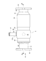
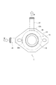
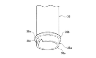
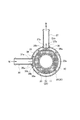
図1は第1実施形態の排気熱回収装置の側面図、図2は図1のA矢視図、図3は図1中B−B線に沿う断面図、図4(a)は同排気熱回収装置の冷却媒体入口管周辺の部分断面図、図4(b)は同冷却媒体入口管の要部の斜視図、図5は図3中C−C線に沿う断面図である。 1 is a side view of the exhaust heat recovery apparatus according to the first embodiment, FIG. 2 is a view taken along the arrow A in FIG. 1, FIG. 3 is a cross-sectional view taken along line BB in FIG. FIG. 4B is a perspective view of the main part of the cooling medium inlet pipe, and FIG. 5 is a sectional view taken along the line CC in FIG.
この排気熱回収装置(排気熱回収器)1は、上流側から下流側へ向かって排気ガスGが流れる図示しない排気管の途中に設けられるもので、図1〜図3に示すように、内管10と外管20と冷却媒体ジャケット部材30と開閉弁16と下流側連絡管50及び取付フランジ18,53等から構成されている。
This exhaust heat recovery device (exhaust heat recovery device) 1 is provided in the middle of an exhaust pipe (not shown) through which exhaust gas G flows from the upstream side toward the downstream side. As shown in FIGS. The
図3に示すように、内管10は、排気ガスGが流れるバイパス通路11を形成する小径の円形配管からなり、その上流側にはテーパ部13を介して大径の上流側連絡管12が一体に形成されている。この上流側連絡管12の上流端には、排気管に接続するための上流側取付フランジ18が溶接で接合されている。
As shown in FIG. 3, the
また、内管10の上流側の管壁の全周には、バイパス通路11の上流端に導入された排気ガスGをバイパス通路11から後述する円環状の熱交換通路21の上流側に導入可能な多数の連通孔15が設けられている。
Further, exhaust gas G introduced to the upstream end of the
さらに、バイパス通路11を構成する内管10の下流端には、開いた状態で排気ガスGをバイパス通路11に流通させ、閉じた状態で排気ガスGを連通孔15を通して円環状の熱交換通路21に図3中実線の矢印のように流通させる開閉弁16が設けられている。この開閉弁16は支軸17を介して後述する下流側連絡管50に開閉自在に取り付けられており、図示しない電気制御アクチュエータにより開閉される。尚、開閉弁16を、冷却媒体温度感知アクチュエータや排気圧感知アクチュエータ等の他のアクチュエータにより開閉させるようにしても良い。
Further, at the downstream end of the
図3及び図5に示すように、外管20は、内管10の外周側に同心に配置され、内管10の外周面10bとの間に円環状の熱交換通路21を形成している。即ち、外管20は、内管10よりも大径の円形管で構成され、その内周面20aに外管20と一体に設けられた円環状の伝熱部材22を備えている。この伝熱部材22は、断面円形の円環状に形成され、その中心部に内管10が挿通する断面円形の中空部22aを有している。また、この円環状の伝熱部材22は、円環状の熱交換通路21の略中央に配置されており、円環状の熱交換通路21を軸方向に流れる排気ガスGから熱を受け取る役目を果たす。尚、円環状の伝熱部材22としては、軸線方向に貫通した多数のセルを伝熱隔壁で画成したハニカム構造体や多数のフィンを放射状に配設したフィン構造体等を使用する。
As shown in FIGS. 3 and 5, the
また、外管20は、その外周側に冷却媒体ジャケット部材30を一体に備えている。冷却媒体ジャケット部材30は、円環状の膨出部31と、その上流側及び下流側のストレート管部32,33とを有し、円環状の膨出部31と外管20との間に円環状の冷却媒体通路35を形成している。この円環状の冷却媒体通路35は、その中を流れる冷却媒体(例えばクーラント)Wに伝熱部材22の受け取った熱を有効に伝えることができるように、円環状の伝熱部材22の外周側に設けられている。尚、円環状の冷却媒体通路35の軸方向長さは、円環状の伝熱部材22の軸方向長さに対応させてある。
Further, the
外管20及び冷却媒体ジャケット部材30は、冷却媒体ジャケット部材30のストレート管部32の端部を円環板状の支持板41を介して上流側連絡管12に溶接で固定し、かつ、冷却媒体ジャケット部材30のストレート管部33の端部を後述する下流側連絡管50内に溶接で固定すると共に、内管10の端部を下流側連絡管50に溶接で固定された円環板状の支持板42に挿通自在(摺動自在)に支持することで、内管10の熱による伸びが吸収されるようになっている。尚、上流側支持板41は閉塞板として構成されているが、下流側支持板42には、排気ガスGを流通させるための開口孔43が形成されている。
The
また、外管20及び冷却媒体ジャケット部材30の下流端には下流側連絡管50が接続され、下流側連絡管50の下流側にテーパ部51を介して設けられた小径連絡管52の下流端には、排気管に接続するための下流側取付フランジ53が溶接で接合されている。
A
また、図3及び図5に示すように、冷却媒体ジャケット部材30の円環状の膨出部31の周壁には円形で一対の取付孔31a,31bが所定距離隔てて形成されており、この一対の取付孔31a,31bには円筒状の冷却媒体入口管36と円筒状の冷却媒体出口管37がそれぞれ取り付けられている。これら冷却媒体入口管36と冷却媒体出口管37は、円環状の冷却媒体通路35の周方向の異なる位置(図示例では、90°周方向に離れた位置)に配置されている。尚、高温の排気ガスGが冷却媒体出口管37の存在する側に流れて冷却媒体出口管37の近傍において冷却媒体Wの過度の加熱(沸騰)により気泡が発生する場合があるので、その気泡発生時の気泡の排出性から、図5に示すように、冷却媒体ジャケット部材30の上部に冷却媒体出口管37を設けた方が良い。
As shown in FIGS. 3 and 5, a pair of mounting
図3及び図4(a),(b)に示すように、円筒状の冷却媒体入口管36の冷却媒体通路35側の端部36aには、低温の冷却媒体Wが冷却媒体通路35の排気ガスGのガス導入側に相対向する部位(冷却媒体Wが沸騰し易い部位)H側に流れるように制御させる制御部材38が設けられている。この制御部材38は、円筒状の冷却媒体入口管36の端部36aを更に円筒状に延ばすことで該端部36aに一体形成されている。即ち、制御部材38は、冷却媒体入口管36の端部36aと一体の円筒状の管材で形成されていて、円環状の冷却媒体通路35の排気ガスGのガス導入側に相対向する部位H側に傾斜部38bを有している。この傾斜部38bは、図4(a)に示すように、冷却媒体入口管36の端部36aと一体に形成された円筒状の管材をその先端部38aから冷却媒体入口管36の鍔部36b側に向けて斜めに切断することにより形成されている。そして、制御部材38の傾斜部38bを円環状の冷却媒体通路35の排気ガスGのガス導入側に相対向する部位H側に向けたことにより、冷却媒体入口管36から供給された低温の冷却媒体Wが円環状の冷却媒体通路35の排気ガスGのガス導入側に相対向する部位H側に流れるようになっている。
As shown in FIGS. 3, 4 (a) and 4 (b), the low-temperature cooling medium W is exhausted from the cooling
また、図4(a)に示すように、制御部材38の先端部38aと外管20の外周面20bとの間には隙間tが形成されている。尚、図4(a)及び図5に示すように、冷却媒体入口管36は、その端部36aを冷却媒体ジャケット部材30の膨出部31の取付孔31aに嵌め込み、鍔部36bを膨出部31に溶接することで冷却媒体ジャケット部材30に固定されている。また、図5に示すように、冷却媒体出口管37は、その端部37aを冷却媒体ジャケット部材30の膨出部31の取付孔31bに嵌め込み、鍔部37bを膨出部31に溶接することで冷却媒体ジャケット部材30に固定されている。
Further, as shown in FIG. 4A, a gap t is formed between the
次に作用を述べる。 Next, the operation will be described.
排気熱回収装置1の開閉弁16が開いている場合には、排気ガスGはバイパス通路11を流れて下流側に到達する。この開閉弁16が開いている時は、排気ガスGはバイパス通路11から円環状の熱交換通路21に流れないため、排気ガスGの熱は、円環状の伝熱部材22に受け渡されることはない。よって、排気ガスGの熱は、円環状の冷却媒体通路35を流れる冷却媒体Wに伝達されて回収されることはない熱の非回収状態となる。
When the on-off
一方、排気熱回収装置1の開閉弁16が閉じている場合には、図3中実線の矢印で示すように、排気ガスGはバイパス通路11から円環状の熱交換通路21に流れ、支持板42の開口孔43を経て下流側連絡管50に流れる。この間に、排気ガスGの熱は、円環状の伝熱部材22に受け渡され、この円環状の伝熱部材22に受け渡され熱が、図5に示すように、円環状の冷却媒体通路35を流れる冷却媒体Wに伝達されて回収される。
On the other hand, when the on-off
この際に、図5に示すように、中心部に内管10が挿通する中空部22aを有する円環状の伝熱部材22が、軸線方向に貫通した多数のセルを伝熱隔壁で画成したハニカム構造体で構成されている場合は、円環状の熱交換通路21を流通する排気ガスGの流れを阻害せずに効率よく排気ガスGの熱を円環状の伝熱部材22で受け取ることができ、熱回収効率の向上を図ることができる。
At this time, as shown in FIG. 5, an annular
この排気熱回収装置1によれば、冷却媒体入口管36の端部36aと一体の円筒状の管材で制御部材38を形成し、この制御部材38が円環状の冷却媒体通路35の排気ガスGのガス導入側に相対向する部位H側に傾斜部38bを有しているため、冷却媒体入口管36から供給された低温の冷却媒体Wが円環状の冷却媒体通路35の排気ガスGのガス導入側に相対向する部位H側に流れるように制御される。即ち、制御部材38に傾斜部38bを形成するだけの簡単な構造により、低温の冷却媒体Wを沸騰し易い部位H側に流れるように制御させることができる。これにより、排気ガスGの加熱で沸騰し易い冷却媒体Wが低温の冷却媒体Wで冷やされるため、排気ガスGの加熱による冷却媒体Wの沸騰を確実に抑制することができる。
According to the exhaust
また、図4(a)に示すように、制御部材38の傾斜部38bを円環状の冷却媒体通路35の排気ガスGのガス導入側に相対向する部位H側に向けたことにより、低温の冷却媒体Wを円環状の冷却媒体通路35の排気ガスGのガス導入側に相対向する部位H側に流すように制御することで、円環状の冷却媒体通路35のガス導入側の冷却媒体流量を上昇させることができるため、排気ガスGの加熱による冷却媒体Wの沸騰を確実に抑制することができる。
Further, as shown in FIG. 4A, the
さらに、冷却媒体入口管36の端部36aを円筒状に延ばして制御部材38を端部36aに一体形成したことにより、冷却媒体入口管36の端部36aに制御部材38を簡単かつ低コストで設けることができる。
Further, the
図6は第2実施形態の排気熱回収装置の冷却媒体入口管周辺の部分断面図、図7は同冷却媒体入口管の要部の斜視図である。 FIG. 6 is a partial cross-sectional view around the cooling medium inlet pipe of the exhaust heat recovery apparatus of the second embodiment, and FIG. 7 is a perspective view of the main part of the cooling medium inlet pipe.
この第2実施形態では、制御部材38は、円環状の冷却媒体通路35の排気ガスGのガス導入側に相対向する部位H側に逆U字状の切欠き部38cを有した冷却媒体入口管36の端部36aと一体の円筒状の管材で形成されている。尚、他の構成は、前記第1実施形態と同様であるため、同一構成部分には、同一符号を付して詳細な説明は省略する。
In the second embodiment, the
この第2実施形態によれば、制御部材38の逆U字状の切欠き部38cを円環状の冷却媒体通路35の排気ガスGのガス導入側に相対向する部位H側に向けたことにより、冷却媒体入口管36から供給された低温の冷却媒体Wを、円環状の冷却媒体通路35の排気ガスGのガス導入側に相対向する部位H側に流れるように制御することができるため、前記第1実施形態と同様に、排気ガスGの加熱による冷却媒体Wの沸騰を確実に抑制することができる。
According to the second embodiment, the inverted
図8は第3実施形態の排気熱回収装置の冷却媒体入口管周辺の部分断面図、図9は同冷却媒体入口管の要部の斜視図である。 FIG. 8 is a partial cross-sectional view of the vicinity of the cooling medium inlet pipe of the exhaust heat recovery apparatus of the third embodiment, and FIG. 9 is a perspective view of the main part of the cooling medium inlet pipe.
この第3実施形態では、制御部材38は、円環状の冷却媒体通路35の排気ガスGのガス導入側に相対向する部位H側に開口部38dを有した冷却媒体入口管36の端部36aと一体の半円筒状の管材で形成されている。尚、他の構成は、前記第1実施形態と同様であるため、同一構成部分には、同一符号を付して詳細な説明は省略する。
In the third embodiment, the
この第3実施形態によれば、制御部材38の開口部38dを円環状の冷却媒体通路35の排気ガスGのガス導入側に相対向する部位H側に向けたことにより、冷却媒体入口管36から供給された低温の冷却媒体Wを、円環状の冷却媒体通路35の排気ガスGのガス導入側に相対向する部位H側に流れるように制御することができるため、前記第1実施形態と同様に、排気ガスGの加熱による冷却媒体Wの沸騰を確実に抑制することができる。
According to the third embodiment, the
図10は第4実施形態の図3中C−C線に沿う断面図である。 FIG. 10 is a sectional view taken along the line CC in FIG. 3 of the fourth embodiment.
この第4実施形態では、冷却媒体入口管36と冷却媒体出口管37の両方の各端部36a,37aに傾斜部38bを有した制御部材38がそれぞれ一体に形成されている。尚、他の構成は、前記第1実施形態と同様であるため、同一構成部分には、同一符号を付して詳細な説明は省略する。
In the fourth embodiment,
この第4実施形態によれば、各制御部材38の傾斜部38bを円環状の冷却媒体通路35の排気ガスGのガス導入側に相対向する部位H側にそれぞれ向けたことにより、冷却媒体入口管36から供給されて冷却媒体出口管37へ流出する低温の冷却媒体Wを、円環状の冷却媒体通路35の排気ガスGのガス導入側に相対向する部位H側に流れるように制御することができるため、前記第1実施形態と同様に、排気ガスGの加熱による冷却媒体Wの沸騰を確実に抑制することができる。
According to the fourth embodiment, the
尚、前記各実施形態では、冷却媒体入口管に制御部材を設けたり、冷却媒体入口管と冷却媒体出口管の両方に制御部材をそれぞれ設けた場合について説明したが、冷却媒体出口管にのみ制御部材を設けても良い。この場合には、冷却媒体出口管の近傍において冷却媒体の過度の加熱(沸騰)により気泡が発生するのを確実に抑制することができる。 In each of the embodiments described above, the control member is provided in the cooling medium inlet pipe, or the control member is provided in both the cooling medium inlet pipe and the cooling medium outlet pipe. However, the control is performed only on the cooling medium outlet pipe. A member may be provided. In this case, it is possible to reliably suppress the generation of bubbles due to excessive heating (boiling) of the cooling medium in the vicinity of the cooling medium outlet pipe.
1 排気熱回収装置
10 内管
11 バイパス通路
15 連通孔
16 開閉弁
20 外管
21 円環状の熱交換通路(環状の熱交換通路)
22 円環状の伝熱部材(環状の伝熱部材)
35 円環状の冷却媒体通路(環状の冷却媒体通路)
36 冷却媒体入口管
36a 端部
37 冷却媒体出口管
37a 端部
38 制御部材
38b 傾斜部
38c 逆U字状の切欠き部
38d 開口部
G 排気ガス
W 冷却媒体
H 冷却媒体通路の排気ガスのガス導入側に相対向する部位(冷却媒体が沸騰し易い部位)
DESCRIPTION OF
22 Annular heat transfer member (annular heat transfer member)
35 Annular coolant passage (annular coolant passage)
36 Cooling
Claims (5)
前記排気ガス(G)が流れるバイパス通路(11)を形成する内管(10)と、
前記内管(10)の外周側に配置され、前記内管(10)の外周との間に環状の熱交換通路(21)を形成する外管(20)と、
前記環状の熱交換通路(21)に配置され、該環状の熱交換通路(21)を軸方向に流れる排気ガス(G)から熱を受け取る環状の伝熱部材(22)と、
前記環状の伝熱部材(22)の受け取った熱を、流通する冷却媒体(W)に伝達するように前記環状の伝熱部材(22)の外周側に配置され、かつ、前記外管(20)の外周側に形成された環状の冷却媒体通路(35)と、
前記環状の冷却媒体通路(35)の周方向の異なる位置に設けられた冷却媒体入口管(36)及び冷却媒体出口管(37)と、
前記内管(10)の上流側の管壁に穿設され、前記バイパス通路(11)の上流端に導入された排気ガス(G)を前記バイパス通路(11)から前記環状の熱交換通路(21)の上流側に導入可能な多数の連通孔(15)と、
前記バイパス通路(11)の下流側に設けられ、開いた状態で排気ガス(G)を前記バイパス通路(11)に流通させ、閉じた状態で排気ガス(G)を前記連通孔(15)を通して前記環状の熱交換通路(21)に流通させる開閉弁(16)と、を備え、
前記冷却媒体入口管(36)と前記冷却媒体出口管(37)の少なくとも一方に、前記冷却媒体(W)を前記環状の冷却媒体通路(35)の前記排気ガス(G)のガス導入側に相対向する部位(H)側に流れるように制御させる制御部材(38)を設けたことを特徴とする排気熱回収装置。 In the exhaust heat recovery device (1) for recovering the exhaust heat by transferring the heat of the exhaust gas (G) to the cooling medium (W) through the heat transfer member (22),
An inner pipe (10) forming a bypass passage (11) through which the exhaust gas (G) flows;
An outer pipe (20) disposed on the outer peripheral side of the inner pipe (10) and forming an annular heat exchange passage (21) with the outer circumference of the inner pipe (10);
An annular heat transfer member (22) disposed in the annular heat exchange passage (21) and receiving heat from exhaust gas (G) flowing in the axial direction through the annular heat exchange passage (21);
It arrange | positions at the outer peripheral side of the said annular heat-transfer member (22) so that the heat received by the said annular heat-transfer member (22) may be transmitted to the circulating cooling medium (W), and the said outer tube (20) ) An annular cooling medium passage (35) formed on the outer peripheral side of
A cooling medium inlet pipe (36) and a cooling medium outlet pipe (37) provided at different positions in the circumferential direction of the annular cooling medium passage (35);
Exhaust gas (G) drilled in the upstream pipe wall of the inner pipe (10) and introduced into the upstream end of the bypass passage (11) is transferred from the bypass passage (11) to the annular heat exchange passage ( 21) a number of communication holes (15) that can be introduced upstream of
Provided downstream of the bypass passage (11), the exhaust gas (G) flows through the bypass passage (11) in an open state, and the exhaust gas (G) passes through the communication hole (15) in a closed state. An on-off valve (16) that circulates in the annular heat exchange passage (21),
The cooling medium (W) is placed on at least one of the cooling medium inlet pipe (36) and the cooling medium outlet pipe (37) on the gas introduction side of the exhaust gas (G) in the annular cooling medium passage (35). An exhaust heat recovery apparatus, characterized in that a control member (38) is provided for controlling the flow so as to flow toward the opposite part (H).
前記制御部材(38)は、前記環状の冷却媒体通路(35)の前記排気ガス(G)のガス導入側に相対向する部位(H)側に傾斜部(38b)を有した筒状の管材で形成されていることを特徴とする排気熱回収装置。 An exhaust heat recovery device (1) according to claim 1,
The control member (38) is a tubular tube member having an inclined portion (38b) on a portion (H) side facing the gas introduction side of the exhaust gas (G) of the annular cooling medium passage (35). An exhaust heat recovery device, characterized in that it is formed by.
前記制御部材(38)は、前記環状の冷却媒体通路(35)の前記排気ガス(G)のガス導入側に相対向する部位(H)側に逆U字状の切欠き部(38c)を有した筒状の管材で形成されていることを特徴とする排気熱回収装置。 An exhaust heat recovery device (1) according to claim 1,
The control member (38) has an inverted U-shaped notch (38c) on the side (H) of the annular cooling medium passage (35) facing the gas introduction side of the exhaust gas (G). An exhaust heat recovery apparatus, characterized in that the exhaust heat recovery apparatus is formed of a cylindrical tubular material.
前記制御部材(38)は、前記環状の冷却媒体通路(35)の前記排気ガス(G)のガス導入側に相対向する部位(H)側に開口部(38d)を有した半筒状の管材で形成されていることを特徴とする排気熱回収装置。 An exhaust heat recovery device (1) according to claim 1,
The control member (38) has a semi-cylindrical shape having an opening (38d) on the side (H) of the annular cooling medium passage (35) facing the gas introduction side of the exhaust gas (G). An exhaust heat recovery device, characterized by being formed of a tube material.
前記制御部材(38)は、前記冷却媒体入口管(36)と前記冷却媒体出口管(37)の少なくとも一方の前記環状の冷却媒体通路(35)側の端部(36a,37a)を筒状に延ばして一体に形成されていることを特徴とする排気熱回収装置。 An exhaust heat recovery device (1) according to any one of claims 2 to 4,
The control member (38) has a cylindrical end (36a, 37a) on the annular cooling medium passage (35) side of at least one of the cooling medium inlet pipe (36) and the cooling medium outlet pipe (37). An exhaust heat recovery device, wherein the exhaust heat recovery device is formed integrally with the exhaust heat.
Priority Applications (1)
| Application Number | Priority Date | Filing Date | Title |
|---|---|---|---|
| JP2016083420A JP2017193972A (en) | 2016-04-19 | 2016-04-19 | Exhaust heat recovery device |
Applications Claiming Priority (1)
| Application Number | Priority Date | Filing Date | Title |
|---|---|---|---|
| JP2016083420A JP2017193972A (en) | 2016-04-19 | 2016-04-19 | Exhaust heat recovery device |
Publications (1)
| Publication Number | Publication Date |
|---|---|
| JP2017193972A true JP2017193972A (en) | 2017-10-26 |
Family
ID=60155313
Family Applications (1)
| Application Number | Title | Priority Date | Filing Date |
|---|---|---|---|
| JP2016083420A Pending JP2017193972A (en) | 2016-04-19 | 2016-04-19 | Exhaust heat recovery device |
Country Status (1)
| Country | Link |
|---|---|
| JP (1) | JP2017193972A (en) |
Cited By (1)
| Publication number | Priority date | Publication date | Assignee | Title |
|---|---|---|---|---|
| JP2020084860A (en) * | 2018-11-21 | 2020-06-04 | フタバ産業株式会社 | Exhaust heat recovery apparatus |
-
2016
- 2016-04-19 JP JP2016083420A patent/JP2017193972A/en active Pending
Cited By (1)
| Publication number | Priority date | Publication date | Assignee | Title |
|---|---|---|---|---|
| JP2020084860A (en) * | 2018-11-21 | 2020-06-04 | フタバ産業株式会社 | Exhaust heat recovery apparatus |
Similar Documents
| Publication | Publication Date | Title |
|---|---|---|
| KR101317373B1 (en) | Heat exchanger | |
| EP2208874B1 (en) | Heat recovery system | |
| CN101405484B (en) | Exhaust gas heat recovery device | |
| WO2010150877A1 (en) | Heat exchanger using multiple-conduit pipes | |
| JP2013539006A (en) | Waste heat boiler | |
| JPWO2016190445A1 (en) | Heat exchanger tank structure and manufacturing method thereof | |
| JP2017203420A (en) | Exhaust heat recovery device | |
| JP2017166403A (en) | Exhaust heat recovery device | |
| JP2006314180A (en) | Thermal power generator | |
| JP2016108980A (en) | Exhaust heat recovery device | |
| JP2007192535A (en) | Heat exchanger device | |
| JP2017193972A (en) | Exhaust heat recovery device | |
| JP2005127684A (en) | Double tube type heat exchanger | |
| JP2006200490A (en) | Exhaust gas cooling device for exhaust gas recirculating system | |
| JP2006266168A (en) | Egr cooler | |
| JP2006200861A (en) | Multi-fluid heat exchanger | |
| JP3180377U (en) | Heat exchanger | |
| CN109945716B (en) | A kind of high-temperature cooler supporting device for heat exchange tube bundle | |
| CN109945718B (en) | A kind of cooling device for preventing high-temperature cooler prime tube bundle support plate from overheating | |
| JP2008175461A (en) | Heat exchanger | |
| US20170343302A1 (en) | Heat exchanger | |
| JP2017002811A (en) | Exhaust heat recovery device | |
| JP2017133362A (en) | Exhaust heat recovery device | |
| JP2006057988A (en) | Heat exchanger for recovering waste heat of combustion type heat source machine | |
| CN214250613U (en) | Wine steam condensing equipment and wine making system |