JP2017193715A - Composite article having fiber with longitudinally-varying geometry - Google Patents
Composite article having fiber with longitudinally-varying geometry Download PDFInfo
- Publication number
- JP2017193715A JP2017193715A JP2017100624A JP2017100624A JP2017193715A JP 2017193715 A JP2017193715 A JP 2017193715A JP 2017100624 A JP2017100624 A JP 2017100624A JP 2017100624 A JP2017100624 A JP 2017100624A JP 2017193715 A JP2017193715 A JP 2017193715A
- Authority
- JP
- Japan
- Prior art keywords
- fiber
- fibers
- cross
- shape
- along
- Prior art date
- Legal status (The legal status is an assumption and is not a legal conclusion. Google has not performed a legal analysis and makes no representation as to the accuracy of the status listed.)
- Granted
Links
- 239000000835 fiber Substances 0.000 title claims abstract description 775
- 239000002131 composite material Substances 0.000 title claims abstract description 159
- 239000011159 matrix material Substances 0.000 claims abstract description 111
- 238000000034 method Methods 0.000 claims description 25
- 230000003068 static effect Effects 0.000 claims description 6
- 238000004519 manufacturing process Methods 0.000 claims description 5
- 230000001902 propagating effect Effects 0.000 claims description 3
- 230000003287 optical effect Effects 0.000 abstract description 14
- 239000003733 fiber-reinforced composite Substances 0.000 abstract description 3
- 239000010410 layer Substances 0.000 description 135
- 239000000463 material Substances 0.000 description 56
- 230000008859 change Effects 0.000 description 25
- 239000011521 glass Substances 0.000 description 11
- 239000011324 bead Substances 0.000 description 9
- 230000008878 coupling Effects 0.000 description 8
- 238000010168 coupling process Methods 0.000 description 8
- 238000005859 coupling reaction Methods 0.000 description 8
- 230000005484 gravity Effects 0.000 description 8
- 238000010521 absorption reaction Methods 0.000 description 5
- 230000000737 periodic effect Effects 0.000 description 5
- -1 polyethylene Polymers 0.000 description 5
- 239000005388 borosilicate glass Substances 0.000 description 4
- 239000000919 ceramic Substances 0.000 description 4
- 230000006870 function Effects 0.000 description 4
- 229910010272 inorganic material Inorganic materials 0.000 description 4
- 239000011147 inorganic material Substances 0.000 description 4
- 230000003993 interaction Effects 0.000 description 4
- 230000035515 penetration Effects 0.000 description 4
- 229920000728 polyester Polymers 0.000 description 4
- 229920002635 polyurethane Polymers 0.000 description 4
- 239000004814 polyurethane Substances 0.000 description 4
- 230000004044 response Effects 0.000 description 4
- 239000004698 Polyethylene Substances 0.000 description 3
- 239000004744 fabric Substances 0.000 description 3
- 230000006872 improvement Effects 0.000 description 3
- 229920000573 polyethylene Polymers 0.000 description 3
- 239000003381 stabilizer Substances 0.000 description 3
- 239000012815 thermoplastic material Substances 0.000 description 3
- 229920001187 thermosetting polymer Polymers 0.000 description 3
- 230000007704 transition Effects 0.000 description 3
- XQUPVDVFXZDTLT-UHFFFAOYSA-N 1-[4-[[4-(2,5-dioxopyrrol-1-yl)phenyl]methyl]phenyl]pyrrole-2,5-dione Chemical compound O=C1C=CC(=O)N1C(C=C1)=CC=C1CC1=CC=C(N2C(C=CC2=O)=O)C=C1 XQUPVDVFXZDTLT-UHFFFAOYSA-N 0.000 description 2
- KXGFMDJXCMQABM-UHFFFAOYSA-N 2-methoxy-6-methylphenol Chemical compound [CH]OC1=CC=CC([CH])=C1O KXGFMDJXCMQABM-UHFFFAOYSA-N 0.000 description 2
- ZOXJGFHDIHLPTG-UHFFFAOYSA-N Boron Chemical compound [B] ZOXJGFHDIHLPTG-UHFFFAOYSA-N 0.000 description 2
- OKTJSMMVPCPJKN-UHFFFAOYSA-N Carbon Chemical compound [C] OKTJSMMVPCPJKN-UHFFFAOYSA-N 0.000 description 2
- 239000004593 Epoxy Substances 0.000 description 2
- 239000004677 Nylon Substances 0.000 description 2
- 239000004696 Poly ether ether ketone Substances 0.000 description 2
- 239000004952 Polyamide Substances 0.000 description 2
- 239000004697 Polyetherimide Substances 0.000 description 2
- 239000004642 Polyimide Substances 0.000 description 2
- 239000004743 Polypropylene Substances 0.000 description 2
- YKTSYUJCYHOUJP-UHFFFAOYSA-N [O--].[Al+3].[Al+3].[O-][Si]([O-])([O-])[O-] Chemical compound [O--].[Al+3].[Al+3].[O-][Si]([O-])([O-])[O-] YKTSYUJCYHOUJP-UHFFFAOYSA-N 0.000 description 2
- NIXOWILDQLNWCW-UHFFFAOYSA-N acrylic acid group Chemical group C(C=C)(=O)O NIXOWILDQLNWCW-UHFFFAOYSA-N 0.000 description 2
- 239000000853 adhesive Substances 0.000 description 2
- 230000001070 adhesive effect Effects 0.000 description 2
- 230000008901 benefit Effects 0.000 description 2
- 229910052796 boron Inorganic materials 0.000 description 2
- 229910052799 carbon Inorganic materials 0.000 description 2
- 230000007423 decrease Effects 0.000 description 2
- 230000000694 effects Effects 0.000 description 2
- NBVXSUQYWXRMNV-UHFFFAOYSA-N fluoromethane Chemical compound FC NBVXSUQYWXRMNV-UHFFFAOYSA-N 0.000 description 2
- 239000003365 glass fiber Substances 0.000 description 2
- 239000002241 glass-ceramic Substances 0.000 description 2
- 239000011229 interlayer Substances 0.000 description 2
- 239000012528 membrane Substances 0.000 description 2
- 239000007769 metal material Substances 0.000 description 2
- 229920001778 nylon Polymers 0.000 description 2
- 239000005304 optical glass Substances 0.000 description 2
- 229920001568 phenolic resin Polymers 0.000 description 2
- 239000005011 phenolic resin Substances 0.000 description 2
- 229920003192 poly(bis maleimide) Polymers 0.000 description 2
- 229920001652 poly(etherketoneketone) Polymers 0.000 description 2
- 229920002647 polyamide Polymers 0.000 description 2
- 239000004417 polycarbonate Substances 0.000 description 2
- 229920000515 polycarbonate Polymers 0.000 description 2
- 229920002530 polyetherether ketone Polymers 0.000 description 2
- 229920001601 polyetherimide Polymers 0.000 description 2
- 229920001721 polyimide Polymers 0.000 description 2
- 229920000642 polymer Polymers 0.000 description 2
- 229920001155 polypropylene Polymers 0.000 description 2
- 230000002787 reinforcement Effects 0.000 description 2
- 239000005368 silicate glass Substances 0.000 description 2
- HBMJWWWQQXIZIP-UHFFFAOYSA-N silicon carbide Chemical compound [Si+]#[C-] HBMJWWWQQXIZIP-UHFFFAOYSA-N 0.000 description 2
- 229910010271 silicon carbide Inorganic materials 0.000 description 2
- 235000012239 silicon dioxide Nutrition 0.000 description 2
- 230000015572 biosynthetic process Effects 0.000 description 1
- 230000000295 complement effect Effects 0.000 description 1
- 230000006835 compression Effects 0.000 description 1
- 238000007906 compression Methods 0.000 description 1
- 230000032798 delamination Effects 0.000 description 1
- 238000006073 displacement reaction Methods 0.000 description 1
- 238000010438 heat treatment Methods 0.000 description 1
- 230000001788 irregular Effects 0.000 description 1
- 210000003734 kidney Anatomy 0.000 description 1
- 230000004048 modification Effects 0.000 description 1
- 238000012986 modification Methods 0.000 description 1
- 239000011368 organic material Substances 0.000 description 1
- 239000002861 polymer material Substances 0.000 description 1
- 230000002028 premature Effects 0.000 description 1
- 230000008569 process Effects 0.000 description 1
- 230000003014 reinforcing effect Effects 0.000 description 1
- 239000007787 solid Substances 0.000 description 1
- 239000013306 transparent fiber Substances 0.000 description 1
- 239000011800 void material Substances 0.000 description 1
- 239000002759 woven fabric Substances 0.000 description 1
Images


Classifications
-
- B—PERFORMING OPERATIONS; TRANSPORTING
- B29—WORKING OF PLASTICS; WORKING OF SUBSTANCES IN A PLASTIC STATE IN GENERAL
- B29C—SHAPING OR JOINING OF PLASTICS; SHAPING OF MATERIAL IN A PLASTIC STATE, NOT OTHERWISE PROVIDED FOR; AFTER-TREATMENT OF THE SHAPED PRODUCTS, e.g. REPAIRING
- B29C70/00—Shaping composites, i.e. plastics material comprising reinforcements, fillers or preformed parts, e.g. inserts
- B29C70/04—Shaping composites, i.e. plastics material comprising reinforcements, fillers or preformed parts, e.g. inserts comprising reinforcements only, e.g. self-reinforcing plastics
- B29C70/06—Fibrous reinforcements only
- B29C70/08—Fibrous reinforcements only comprising combinations of different forms of fibrous reinforcements incorporated in matrix material, forming one or more layers, and with or without non-reinforced layers
- B29C70/083—Combinations of continuous fibres or fibrous profiled structures oriented in one direction and reinforcements forming a two dimensional structure, e.g. mats
-
- F—MECHANICAL ENGINEERING; LIGHTING; HEATING; WEAPONS; BLASTING
- F16—ENGINEERING ELEMENTS AND UNITS; GENERAL MEASURES FOR PRODUCING AND MAINTAINING EFFECTIVE FUNCTIONING OF MACHINES OR INSTALLATIONS; THERMAL INSULATION IN GENERAL
- F16S—CONSTRUCTIONAL ELEMENTS IN GENERAL; STRUCTURES BUILT-UP FROM SUCH ELEMENTS, IN GENERAL
- F16S1/00—Sheets, panels, or other members of similar proportions; Constructions comprising assemblies of such members
- F16S1/10—Composite members, e.g. with ribs or flanges attached
-
- B—PERFORMING OPERATIONS; TRANSPORTING
- B29—WORKING OF PLASTICS; WORKING OF SUBSTANCES IN A PLASTIC STATE IN GENERAL
- B29C—SHAPING OR JOINING OF PLASTICS; SHAPING OF MATERIAL IN A PLASTIC STATE, NOT OTHERWISE PROVIDED FOR; AFTER-TREATMENT OF THE SHAPED PRODUCTS, e.g. REPAIRING
- B29C70/00—Shaping composites, i.e. plastics material comprising reinforcements, fillers or preformed parts, e.g. inserts
- B29C70/04—Shaping composites, i.e. plastics material comprising reinforcements, fillers or preformed parts, e.g. inserts comprising reinforcements only, e.g. self-reinforcing plastics
- B29C70/06—Fibrous reinforcements only
- B29C70/10—Fibrous reinforcements only characterised by the structure of fibrous reinforcements, e.g. hollow fibres
- B29C70/16—Fibrous reinforcements only characterised by the structure of fibrous reinforcements, e.g. hollow fibres using fibres of substantial or continuous length
-
- B—PERFORMING OPERATIONS; TRANSPORTING
- B29—WORKING OF PLASTICS; WORKING OF SUBSTANCES IN A PLASTIC STATE IN GENERAL
- B29C—SHAPING OR JOINING OF PLASTICS; SHAPING OF MATERIAL IN A PLASTIC STATE, NOT OTHERWISE PROVIDED FOR; AFTER-TREATMENT OF THE SHAPED PRODUCTS, e.g. REPAIRING
- B29C70/00—Shaping composites, i.e. plastics material comprising reinforcements, fillers or preformed parts, e.g. inserts
- B29C70/04—Shaping composites, i.e. plastics material comprising reinforcements, fillers or preformed parts, e.g. inserts comprising reinforcements only, e.g. self-reinforcing plastics
- B29C70/28—Shaping operations therefor
- B29C70/54—Component parts, details or accessories; Auxiliary operations, e.g. feeding or storage of prepregs or SMC after impregnation or during ageing
- B29C70/545—Perforating, cutting or machining during or after moulding
-
- B—PERFORMING OPERATIONS; TRANSPORTING
- B32—LAYERED PRODUCTS
- B32B—LAYERED PRODUCTS, i.e. PRODUCTS BUILT-UP OF STRATA OF FLAT OR NON-FLAT, e.g. CELLULAR OR HONEYCOMB, FORM
- B32B17/00—Layered products essentially comprising sheet glass, or glass, slag, or like fibres
- B32B17/06—Layered products essentially comprising sheet glass, or glass, slag, or like fibres comprising glass as the main or only constituent of a layer, next to another layer of a specific material
- B32B17/067—Layered products essentially comprising sheet glass, or glass, slag, or like fibres comprising glass as the main or only constituent of a layer, next to another layer of a specific material of fibres or filaments
-
- B—PERFORMING OPERATIONS; TRANSPORTING
- B32—LAYERED PRODUCTS
- B32B—LAYERED PRODUCTS, i.e. PRODUCTS BUILT-UP OF STRATA OF FLAT OR NON-FLAT, e.g. CELLULAR OR HONEYCOMB, FORM
- B32B18/00—Layered products essentially comprising ceramics, e.g. refractory products
-
- B—PERFORMING OPERATIONS; TRANSPORTING
- B32—LAYERED PRODUCTS
- B32B—LAYERED PRODUCTS, i.e. PRODUCTS BUILT-UP OF STRATA OF FLAT OR NON-FLAT, e.g. CELLULAR OR HONEYCOMB, FORM
- B32B27/00—Layered products comprising a layer of synthetic resin
- B32B27/04—Layered products comprising a layer of synthetic resin as impregnant, bonding, or embedding substance
-
- B—PERFORMING OPERATIONS; TRANSPORTING
- B32—LAYERED PRODUCTS
- B32B—LAYERED PRODUCTS, i.e. PRODUCTS BUILT-UP OF STRATA OF FLAT OR NON-FLAT, e.g. CELLULAR OR HONEYCOMB, FORM
- B32B5/00—Layered products characterised by the non- homogeneity or physical structure, i.e. comprising a fibrous, filamentary, particulate or foam layer; Layered products characterised by having a layer differing constitutionally or physically in different parts
- B32B5/22—Layered products characterised by the non- homogeneity or physical structure, i.e. comprising a fibrous, filamentary, particulate or foam layer; Layered products characterised by having a layer differing constitutionally or physically in different parts characterised by the presence of two or more layers which are next to each other and are fibrous, filamentary, formed of particles or foamed
- B32B5/24—Layered products characterised by the non- homogeneity or physical structure, i.e. comprising a fibrous, filamentary, particulate or foam layer; Layered products characterised by having a layer differing constitutionally or physically in different parts characterised by the presence of two or more layers which are next to each other and are fibrous, filamentary, formed of particles or foamed one layer being a fibrous or filamentary layer
- B32B5/28—Layered products characterised by the non- homogeneity or physical structure, i.e. comprising a fibrous, filamentary, particulate or foam layer; Layered products characterised by having a layer differing constitutionally or physically in different parts characterised by the presence of two or more layers which are next to each other and are fibrous, filamentary, formed of particles or foamed one layer being a fibrous or filamentary layer impregnated with or embedded in a plastic substance
-
- B—PERFORMING OPERATIONS; TRANSPORTING
- B64—AIRCRAFT; AVIATION; COSMONAUTICS
- B64C—AEROPLANES; HELICOPTERS
- B64C1/00—Fuselages; Constructional features common to fuselages, wings, stabilising surfaces or the like
-
- F—MECHANICAL ENGINEERING; LIGHTING; HEATING; WEAPONS; BLASTING
- F41—WEAPONS
- F41H—ARMOUR; ARMOURED TURRETS; ARMOURED OR ARMED VEHICLES; MEANS OF ATTACK OR DEFENCE, e.g. CAMOUFLAGE, IN GENERAL
- F41H5/00—Armour; Armour plates
- F41H5/02—Plate construction
- F41H5/04—Plate construction composed of more than one layer
-
- Y—GENERAL TAGGING OF NEW TECHNOLOGICAL DEVELOPMENTS; GENERAL TAGGING OF CROSS-SECTIONAL TECHNOLOGIES SPANNING OVER SEVERAL SECTIONS OF THE IPC; TECHNICAL SUBJECTS COVERED BY FORMER USPC CROSS-REFERENCE ART COLLECTIONS [XRACs] AND DIGESTS
- Y02—TECHNOLOGIES OR APPLICATIONS FOR MITIGATION OR ADAPTATION AGAINST CLIMATE CHANGE
- Y02T—CLIMATE CHANGE MITIGATION TECHNOLOGIES RELATED TO TRANSPORTATION
- Y02T50/00—Aeronautics or air transport
- Y02T50/40—Weight reduction
-
- Y—GENERAL TAGGING OF NEW TECHNOLOGICAL DEVELOPMENTS; GENERAL TAGGING OF CROSS-SECTIONAL TECHNOLOGIES SPANNING OVER SEVERAL SECTIONS OF THE IPC; TECHNICAL SUBJECTS COVERED BY FORMER USPC CROSS-REFERENCE ART COLLECTIONS [XRACs] AND DIGESTS
- Y10—TECHNICAL SUBJECTS COVERED BY FORMER USPC
- Y10T—TECHNICAL SUBJECTS COVERED BY FORMER US CLASSIFICATION
- Y10T29/00—Metal working
- Y10T29/49—Method of mechanical manufacture
- Y10T29/49826—Assembling or joining
- Y10T29/49863—Assembling or joining with prestressing of part
-
- Y—GENERAL TAGGING OF NEW TECHNOLOGICAL DEVELOPMENTS; GENERAL TAGGING OF CROSS-SECTIONAL TECHNOLOGIES SPANNING OVER SEVERAL SECTIONS OF THE IPC; TECHNICAL SUBJECTS COVERED BY FORMER USPC CROSS-REFERENCE ART COLLECTIONS [XRACs] AND DIGESTS
- Y10—TECHNICAL SUBJECTS COVERED BY FORMER USPC
- Y10T—TECHNICAL SUBJECTS COVERED BY FORMER US CLASSIFICATION
- Y10T428/00—Stock material or miscellaneous articles
- Y10T428/249921—Web or sheet containing structurally defined element or component
- Y10T428/249924—Noninterengaged fiber-containing paper-free web or sheet which is not of specified porosity
- Y10T428/249928—Fiber embedded in a ceramic, glass, or carbon matrix
-
- Y—GENERAL TAGGING OF NEW TECHNOLOGICAL DEVELOPMENTS; GENERAL TAGGING OF CROSS-SECTIONAL TECHNOLOGIES SPANNING OVER SEVERAL SECTIONS OF THE IPC; TECHNICAL SUBJECTS COVERED BY FORMER USPC CROSS-REFERENCE ART COLLECTIONS [XRACs] AND DIGESTS
- Y10—TECHNICAL SUBJECTS COVERED BY FORMER USPC
- Y10T—TECHNICAL SUBJECTS COVERED BY FORMER US CLASSIFICATION
- Y10T428/00—Stock material or miscellaneous articles
- Y10T428/249921—Web or sheet containing structurally defined element or component
- Y10T428/249924—Noninterengaged fiber-containing paper-free web or sheet which is not of specified porosity
- Y10T428/24994—Fiber embedded in or on the surface of a polymeric matrix
-
- Y—GENERAL TAGGING OF NEW TECHNOLOGICAL DEVELOPMENTS; GENERAL TAGGING OF CROSS-SECTIONAL TECHNOLOGIES SPANNING OVER SEVERAL SECTIONS OF THE IPC; TECHNICAL SUBJECTS COVERED BY FORMER USPC CROSS-REFERENCE ART COLLECTIONS [XRACs] AND DIGESTS
- Y10—TECHNICAL SUBJECTS COVERED BY FORMER USPC
- Y10T—TECHNICAL SUBJECTS COVERED BY FORMER US CLASSIFICATION
- Y10T428/00—Stock material or miscellaneous articles
- Y10T428/29—Coated or structually defined flake, particle, cell, strand, strand portion, rod, filament, macroscopic fiber or mass thereof
- Y10T428/2913—Rod, strand, filament or fiber
- Y10T428/2922—Nonlinear [e.g., crimped, coiled, etc.]
-
- Y—GENERAL TAGGING OF NEW TECHNOLOGICAL DEVELOPMENTS; GENERAL TAGGING OF CROSS-SECTIONAL TECHNOLOGIES SPANNING OVER SEVERAL SECTIONS OF THE IPC; TECHNICAL SUBJECTS COVERED BY FORMER USPC CROSS-REFERENCE ART COLLECTIONS [XRACs] AND DIGESTS
- Y10—TECHNICAL SUBJECTS COVERED BY FORMER USPC
- Y10T—TECHNICAL SUBJECTS COVERED BY FORMER US CLASSIFICATION
- Y10T428/00—Stock material or miscellaneous articles
- Y10T428/29—Coated or structually defined flake, particle, cell, strand, strand portion, rod, filament, macroscopic fiber or mass thereof
- Y10T428/2913—Rod, strand, filament or fiber
- Y10T428/2973—Particular cross section
- Y10T428/2976—Longitudinally varying
Abstract
Description
本発明は、概して複合部品に関し、具体的には、弾道性能及び光学性能を改善させた繊維強化複合品に関する。 The present invention relates generally to composite parts, and in particular to fiber reinforced composite articles having improved ballistic and optical performance.
複合構造は、典型的には、繊維を埋め込んで強化したマトリックスから構成される。複合構造は、典型的には、繊維の長さに沿って荷重を伝達するように設計される。一の繊維からの荷重は、マトリックス材を通過することにより、同じ層内の別の繊維に移動するか、又は隣接する層内の繊維に移動する。しかしながら、通常マトリックスは繊維より弱いため、マトリックスを通って一の繊維から別の繊維へ伝達される荷重が大きすぎると、マトリックスが破壊される。マトリックスが破壊されると、複合構造内で繊維が移動可能となる。 A composite structure is typically composed of a matrix embedded with fibers and reinforced. Composite structures are typically designed to transmit loads along the length of the fiber. The load from one fiber moves through the matrix material to another fiber in the same layer or to a fiber in an adjacent layer. However, since the matrix is usually weaker than the fibers, if the load transmitted from one fiber to another through the matrix is too great, the matrix is destroyed. When the matrix is broken, the fibers can move within the composite structure.
複合パネルが弾丸による衝撃を受ける弾道事象の間に、繊維がマトリックス内部で移動可能であることは、複合パネルの弾道性能に影響を与えうる。例えば、マトリックス内の繊維が移動であることは、弾丸の貫通に対する複合パネルの耐性に影響を与えうる。透明な複合パネルの場合、マトリックスに対して繊維が移動することは、複合パネルの光学性能にも影響を与えうる。これに関して、弾道事象の間にマトリックスに対して繊維が移動することは、弾丸の衝撃によって光学性能が低下する領域の大きさに影響を与えうる。 The ability of fibers to move within the matrix during a ballistic event where the composite panel is impacted by a bullet can affect the ballistic performance of the composite panel. For example, the movement of the fibers in the matrix can affect the composite panel's resistance to bullet penetration. In the case of a transparent composite panel, the movement of fibers relative to the matrix can also affect the optical performance of the composite panel. In this regard, the movement of fibers relative to the matrix during a ballistic event can affect the size of the area where optical performance is degraded by the impact of a bullet.
したがって、従来技術には、マトリックス内における繊維の移動を制御することにより複合構造の弾道性能及び光学性能を改善した複合構造に対する需要が存在する。 Accordingly, there is a need in the prior art for composite structures that improve the ballistic and optical performance of the composite structure by controlling the movement of fibers within the matrix.
本発明は、複合品に関連した上記需要に特に対処してそれに応えるものであり、一実施形態において、マトリックスと、マトリックスに埋め込まれた複数の繊維を有する複合品を提供する。繊維の一つ一つは、繊維長と繊維形状を有する。繊維の少なくとも一部の繊維形状は、繊維長に沿って変化しうる。 The present invention addresses and responds specifically to the above demands associated with composite articles, and in one embodiment provides a composite article having a matrix and a plurality of fibers embedded in the matrix. Each of the fibers has a fiber length and a fiber shape. The fiber shape of at least a portion of the fibers can vary along the fiber length.
さらなる実施形態では、複合品の製造方法が開示される。この方法は、各々が繊維長と繊維形状とを有する複数の繊維を提供するステップを含む。方法は、さらに、繊維の少なくとも一部について、繊維長に沿って繊維形状を変えるステップを含む。方法は、加えて、マトリックス中に繊維を埋め込むステップを含む。 In a further embodiment, a method for manufacturing a composite article is disclosed. The method includes providing a plurality of fibers each having a fiber length and a fiber shape. The method further includes changing the fiber shape along the fiber length for at least a portion of the fibers. The method additionally includes the step of embedding fibers in the matrix.
さらには、ビークルの複合パネルのような複合品の装着方法が開示される。この方法は、各々が繊維長と、繊維長に沿って変化する繊維形状とを有する複数の繊維がマトリックスに埋め込まれた複合品を提供することを含む。方法は、静的装着条件を満たす第1の状態で複合品を配置することを含みうる。方法は、さらに、動的装着条件を満たす第2の状態で複合品を配置することを含みうる。 Furthermore, a method for mounting a composite item such as a composite panel of a vehicle is disclosed. The method includes providing a composite article in which a plurality of fibers, each having a fiber length and a fiber shape that varies along the fiber length, are embedded in a matrix. The method can include placing the composite article in a first state that satisfies a static mounting condition. The method may further include placing the composite article in a second state that satisfies the dynamic loading condition.
有利には、繊維形状の変化により、繊維とマトリックスとの機械的連結が向上する。さらに、繊維形状の変化により、隣接する繊維間の機械的連結が向上する。繊維形状の変化によって提供される機械的連結は、マトリックスに対する繊維の移動を制御する手段となりうる。機械的連結は、直接隣接する繊維のすべり又は移動を制御する手段となりうる。 Advantageously, the change in fiber shape improves the mechanical connection between the fiber and the matrix. Furthermore, the mechanical connection between adjacent fibers is improved by the change in the fiber shape. The mechanical connection provided by the change in fiber shape can be a means to control the movement of the fiber relative to the matrix. Mechanical coupling can be a means of controlling the sliding or movement of directly adjacent fibers.
繊維のすべりを制御することは、繊維の、衝撃事象に関与する繊維長の部分を制御する手段となりうる。衝撃事象に関与する繊維の長さを制御することにより、繊維のエネルギー吸収能が向上し、これにより、弾丸による衝撃に対する複合品の弾道性能及び/又は光学性能が向上する。 Controlling the slip of the fiber can be a means of controlling the portion of the fiber that is involved in the impact event. By controlling the length of the fiber involved in the impact event, the energy absorption capacity of the fiber is improved, thereby improving the ballistic performance and / or optical performance of the composite against impact by a bullet.
上述のフィーチャ、機能及び利点は、本発明の様々な実施形態において独立して達成可能であるか、又は他の実施形態において組み合わせることができる。これらの実施形態について、後述の説明及び添付図面を参照してさらに詳細に説明する。 The features, functions and advantages described above can be achieved independently in various embodiments of the invention or can be combined in other embodiments. These embodiments will be described in more detail with reference to the following description and attached drawings.
本発明の上述のフィーチャ及び他のフィーチャは、添付図面からさらに明らかとなる。図面を通して、同様の参照番号は同様の部品を示す。 These and other features of the present invention will become more apparent from the accompanying drawings. Throughout the drawings, like reference numbers indicate like parts.
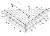
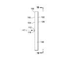
ここで、本発明の好適な種々の実施形態を例示することを目的とする図面を参照する。図1は複合品10を示している。複合品10は、マトリックス18と、マトリックス18内部に埋め込まれた複数の繊維22とを含む繊維強化複合パネル14として製作される。有利には、繊維22は、繊維22の長さに沿って変化する繊維形状32を備える。繊維22の繊維長34に沿った繊維形状32の変化は、繊維22とマトリックス18との間の機械的連結(例えば、繊維−マトリックス間の連結)を促進する。繊維22の繊維長34に沿った繊維形状32の変化は、同一層20内において隣接する繊維22間の機械的連結、及び/又は異なる層20内における繊維22間の機械的連結も促進することができる。
Reference will now be made to the drawings which are intended to illustrate various preferred embodiments of the invention. FIG. 1 shows a
繊維−マトリックス間の機械的連結は、マトリックス18に対する繊維22の移動又はすべりを制御する手段を提供する。繊維−繊維間の機械的連結は、繊維−繊維間の移動又はすべりを制御する手段を提供する。繊維22の長さに沿って繊維形状32を変化させることにより、繊維長34の、衝撃事象に関与する部分を制御することができる。有利には、繊維長34に沿って繊維形状32を変化させることにより、複合品10に激突又は進入する弾丸を減速させる能力が向上する。
The fiber-matrix mechanical connection provides a means of controlling the movement or sliding of the
繊維22とマトリックス18との間のすべりの量は、複合品10に弾丸が入った距離又は深さの関数として、繊維22の破壊を制御する手段にもなりうる。これに関して、本発明は、有利には、各繊維22の、弾丸事象に関与する長さ部分を制御するか、又は選択的に増加させることにより、各繊維22中の引張ひずみを分散させる繊維22の長さを増加させることができるという技術的効果を提供する。繊維22の、弾丸事象に関与する長さ部分を制御する(例えば、増加させる)ことにより、衝撃事象の間に繊維22によって吸収される総エネルギー量を制御する(例えば、増大させる)ことができる。これに関して、繊維22中の引張荷重は、繊維22が最大ひずみ値に達するときの繊維22の早期破損を防ぐ手段として制御可能である。
The amount of slip between the
さらに、繊維長34に沿って繊維形状32を選択的に変化させることにより、繊維が弾道衝撃事象に関与する時間の量を制御する手段として繊維22の相対的な移動を制御することができる。繊維が弾道衝撃事象に関与する時間の量は、弾丸を減速させて繊維22によって吸収されうる弾丸エネルギーの量を増加させるために繊維22が有する時間の量の増加に相関しうる。マトリックス18に対する、及び互いに対する繊維22のすべりを制御することは、さらに、適切な最大ひずみ値及び/又は適切なひずみ速度応答を有する材料から繊維22を形成することにより、影響を受けるか、又は改善する。これについては後述でさらに詳細に説明する。これに関して、繊維22は、繊維22の破壊を防ぐとともに弾丸による複合品10の貫通に抵抗する又は貫通を防止する最大ひずみを有する材料から形成することができる。
Furthermore, by selectively changing the
図1は、表面12を有する複合品10を示している。複合品10は、パネル表面16と、マトリックス18内部に埋め込まれた複数の繊維22とを含む複合パネル14として形成されている。繊維22は、マトリックス18の構造強化として機能し、複合品10の機械性能及び弾道性能を向上させることができる。これに関して、繊維22は、繊維22の引張強さ、及び目標弾性係数(例えば、剛性)を高める結果として複合品10の特定の剛性を調整する構造強化を提供する。本明細書では、強度、ひずみ、及び剛性といった特性は、動的特性又は高ひずみ速度特性の観点から記載される。
FIG. 1 shows a
図2は、図1の複合品10又は複合パネル14の分解図であり、複数の層20を示している。層20の各々において、繊維22は、横並び70の構成に配置されている。各繊維22は、繊維長34と長手軸36とを有している。各層20内の繊維22の繊維形状32は、繊維長34に沿って変化している。繊維形状32は、断面積38及び断面形状40から構成され、それらの一方又は両方は、繊維長34に沿って変化することができる。各層20内の繊維22は互いに概ね整列しており、所与の層20内の繊維22の長手軸36はほぼ平行である。しかしながら、本明細書に記載される実施形態のいずれにおいても、繊維22は、マトリックス内において織物層(図示しない)に組み込むことができ、層内において互いに横並びに整列した関係に限定されることも、層内において互いにほぼ平行な関係に限定されることもない。さらに、ここに開示される繊維22の実施形態のいずれもが、マトリックスを有さないファブリック(図示しない)において実施することができ、この場合、繊維−繊維の連結により、本明細書に記載したものと同様にして、弾丸によるファブリックの貫通抵抗に関する利点が提供される。
FIG. 2 is an exploded view of the
一実施形態では、一の層20内の繊維22の長手軸36の方向は、直接隣接する層20内の繊維22の長手軸36に対して角度を有している。例えば、図2には、一の層20内の繊維22の長手軸36が、それに直接隣接する層20内の繊維22の長手軸36に対して直角である様子が示されている。しかしながら、隣接する層20の繊維22の長手軸36は、複合品10の所望のプライの積み重ねに応じて、互いにどのような角度に配向されてもよい。
In one embodiment, the direction of the
図3は、図2の複合品10の部分拡大図であり、複数の層20を示している。層20の各々は、繊維長34に沿って変化する繊維形状32を有する繊維22を含んでいる。図示のように、層20は、直接隣接する層20の繊維22に対して任意の方向に配向されうる繊維22を含む。例えば、図3には、一の層20の繊維22が、直接隣接する層20の繊維22に対して直角に配向されている交差プライ構成が示されている。図3は、複合品10の非限定的な一実施形態を示しているのであって、マトリックス18内部における繊維22の代替え的構成を制限しているのではない。例えば、層20内の繊維22は、図3に示すように、他の層20内の繊維22に対して直角に配向されても、垂直でない方向(例えば、15度、22.5度、45度、60度、75度など)に配向されてもよい。
FIG. 3 is a partially enlarged view of the
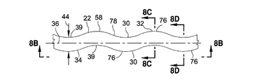
図4は、繊維22の繊維長34に沿った繊維形状32の変化を示す繊維22からなる層20の上面図である。繊維22の繊維形状32は、繊維長34に沿った所与の位置における繊維22の断面積38(図3)、及び/又は繊維長34に沿った所与の位置における繊維22の断面形状を特徴とする。しかしながら、繊維形状32は、限定しないが、繊維22の第1の部分52と繊維22の第2の部分54との間の遷移の形状を含む他のパラメータを特徴としてもよい。例えば、繊維形状32は、図4に示すような、第1の部分52と第2の部分54との間の、丸みを帯びた遷移、又は半径が滑らかに変化する遷移を特徴とすることができる。異なる構成では、形状は、図12A〜12Dの実施形態に示して後述するような、比較的はっきりとした繊維、又は急激な遷移を特徴とすることができる。
FIG. 4 is a top view of the
図4では、繊維形状32は、繊維長34に沿って周期的58に変化している。これに関して、繊維22は、間にほぼ均一な間隔を置いてほぼ一様に分散された一連の第2の部分54を含むことができる。二つの第2の部分は、それぞれ第1の部分52によって分離されている。繊維形状32の周期的58な構成は、繊維長34に沿って反復されるほぼ類似した繊維形状32からなる。本明細書には、繊維長34に沿って周期的58に変化する繊維形状32が記載されているが、繊維22は半周期的64に(図15)変化する繊維形状32を具備してもよい。例えば、繊維22の第2の部分間の間隔が次第に又は漸次増加又は減少するというように、隣接する二つの第2の部分54の間の距離が次第に大きくなるか、又は次第に小さくなるように、繊維形状32を変化させることができる。加えて、繊維形状32は、繊維22の繊維長34の任意の部分に沿って反復式に変化させてもよい(例えば、図15)。繊維形状32は、繊維超34に沿って非周期的に、又はランダムに(図示しない)構成してもよい。
In FIG. 4, the
図4では、各繊維22はほぼ同様に構成されている。繊維22はそれぞれ側面30を有し、隣接する繊維22との間に空隙72が形成されるように構成されている。空隙72の各々は、繊維22がマトリックス18内部に埋め込まれると実質的にマトリックス18材で充填される。繊維22の繊維長34に沿った繊維形状32の変化は、繊維22とマトリックス18との間の機械的連結を向上させる。加えて、図4に示すように、繊維22は、繊維22の第2の部分54が隣接する繊維22の第1の部分52と少なくとも部分的に入れ子74になるように構成することができる。有利には、繊維22の少なくとも部分的な入れ子関係により、繊維22の機械的連結(例えば、繊維−繊維の連結)が向上する。上述のように、繊維22の機械的連結は、繊維−繊維間のすべり又は移動を低減することができ、これにより繊維長34の、弾道事象に関与する部分を制御する手段が提供される。これに関して、繊維−繊維間のすべりが低減すると、弾道事象に関与する繊維22の量が増大しうる。弾道事象に関与する繊維22の量が増大すると、繊維22の全体的なエネルギー吸収能が増大し、これにより、上述のように、複合品10の弾道性能及び/又は衝撃後光学性能が向上しうる。
In FIG. 4, each
図5Aは、図4の繊維22の上面図である。図示の実施形態では、繊維形状32の変化は、繊維長34に沿って第1の部分52と第2の部分54とが周期的58に変化することからなっている。長手軸36に関してほぼ対称な構成を有するように図示されているが、長手軸36の一方の側の繊維22の構成が長手軸36の反対側の繊維22の構成と異なる非対称な構成(図示しない)を有する繊維形状32も考慮可能である。繊維22は、繊維長34に沿った任意の位置における繊維22の最大幅と定義される繊維幅44を有する。本明細書に開示される繊維の実施形態のいずれにおいても、図示の繊維形状は分り易く示すために誇張されているか、又は誇張されていない。
FIG. 5A is a top view of the
図5Bは、図5Aの繊維22の側面図である。繊維22は概ね平坦な構成を有し、繊維長34に沿ってほぼ一定な繊維厚42を定義する互いにほぼ平行な上面26と下面28とを有している。繊維22の繊維厚42は、繊維幅44に垂直に測定されたものと定義される。一実施形態においては、繊維22の上面26と下面28とは、互いに平行でなくともよい。
FIG. 5B is a side view of the
図5Cは、図5Aの繊維22の第1の部分52の断面である。繊維形状32(図5A)は、断面積38及び断面形状40(図3)を有している。図5Cでは、繊維22の第1の部分52は第1の断面積38aと、長方形の第1の断面形状40aとを有している。長方形の断面形状は、短軸86と長軸88とを有している。図5Dは、第2の断面積38bと、長方形である第1の断面形状40aに類似の第2の断面形状40bとを有する第2の部分54(図5A)を示している。これに関して、図5A〜5Dは、繊維長34(図5A)に沿って断面積38が可変であり、繊維長34に沿って断面形状40がほぼ一定(例えば、長方形)である繊維22(図5B)の一実施形態を表している。図5Aの繊維22の繊維長34に沿った断面積38が変化するのは、長軸88に沿って長方形の断面形状40のアスペクト比が増大するためである。図5A〜5Dに示す繊維22の実施形態は、面内方向内での(例えば、層内での)繊維−繊維間の機械的連結を促進する。
FIG. 5C is a cross section of the
図6Aは、別の実施形態による繊維22の一つの上面図であり、繊維22は第1の部分52と第2の部分54とを交互に含んでいる。第2の部分54は、繊維22を少なくとも部分的に又は完全に貫通する穴又はスロットのような開口66を含んでいる。有利には、繊維22の第2の部分54は、繊維長34に沿って、繊維22の第1の部分52の断面形状が繊維22の第2の部分54の断面形状に対して変化するように構成される。加えて、図6Aに示す実施形態では、繊維22の第2の部分54の断面積は、繊維22の第1の部分52の断面積とほぼ等しい。繊維22の荷重担持能(例えば、引張荷重)は、繊維22の長さに沿った任意の地点における最小断面積の荷重担持能に限定される。図6Aでは、繊維22の最小断面積は第1の部分52に位置している。第2の部分54の断面積を第1の部分52の断面積にほぼ等しく制限することにより、繊維22の断面積の拡大に関連付けられる重量ペナルティがあったとしても、それは最小化される。
FIG. 6A is a top view of one of the
図6Bは、図6Aの繊維22の側面図である。繊維22は、図5A〜5Dの実施形態の繊維22について上述したように、概ね平坦な構成を有している。これに関して、図6A〜6Dに示される繊維22は、繊維長34に沿ってほぼ一定の繊維厚42を有している。しかしながら、一実施形態では、一定でない厚みを有する繊維22が使用されうる。
6B is a side view of the
図6Cは、図6Aの繊維22の第1の部分52の断面である。第1の部分52における繊維形状32は、第1の断面積38aを取り囲む、斜線の長方形部により表された第1の断面形状40aからなる。図6Dは、第2の断面積38bと第2の断面形状40bとを有する第2の部分54を示している。第2の断面形状40bは、二つの斜線領域の間の開口66によって分割された繊維22の概ね長方形の形状である。第2の部分54の第2の断面形状40bは、一対の斜線領域からなる総面積を含む。図6Dに示す一対の斜線部の総面積は、図6Cの斜線部の面積にほぼ等しい。これに関して、図6A〜6Dは、繊維22の断面積38が繊維長34(図6A)に沿ってほぼ一定であり、断面形状が繊維長34に沿って可変であるように構成された多数の繊維実施形態の一つを示している。
6C is a cross section of the
図7は、繊維長34に沿って変化する繊維形状32を有する繊維22の一実施形態を示している。繊維形状32は、互いに交互に並ぶ一連の第1の部分52と第2の部分54とからなっている。図では、第1の部分52及び第2の部分54は、繊維長34に沿って周期的58に配置されている。しかしながら、上述のように、繊維形状32は、図15に示して後述するように、半周期的64に構成されてもよい。繊維形状32は、非周期的に変化するように構成されてもよい。
FIG. 7 illustrates one embodiment of a
図7Bに示すように、繊維22は、繊維22の第1の部分52(図7A)を表す円形状の第1の断面積38aと第1の断面形状40aとを有している。図7Cは、やはり円形状の第2の断面積38bと第2の断面形状40bとを有する繊維22の第2の部分(図7A)を示している。図7A〜7Cは、繊維長34(図7A)に沿って変化する断面積38(図7C)と、繊維長34に沿ってほぼ一定の断面形状40とを有する繊維22の一実施形態を示している。図7B〜7Cにおける断面積38の変化は、円形の断面形状40の大きさの、半径方向に一定の増加又は拡大によるものである。
As shown in FIG. 7B, the
一実施形態では、繊維22の第2の部分54(図7A)の第2の断面積38b(図7C)は、第1の部分52(図7A)の第1の断面積38a(図7B)より、第1の部分の約50%未満だけ大きくすることができる。しかしながら、第1の部分の第1の断面積38aより、第1の部分の約50%を超える分だけ大きい第2の部分54の第2の断面積38bを有する繊維22が供給される実施形態も可能である。本明細書では、各第2の部分54の第2の断面積38bは、第1の部分52又は繊維コア50(図7A)の第1の断面積38aを包含、包囲、又は他の方法で含む。上述のように、繊維22の荷重担持能(例えば、引張荷重)は、第1の部分52に位置する繊維22最小断面の荷重担持能によって決定される。第2の部分54の大きさを制限することにより、繊維22の荷重を担持しない部分に関連付けられる重量ペナルティ及び/又はコスト的ペナルティは最小化される。
In one embodiment, the second
有利には、図7A〜7Cに示す繊維22の実施形態は、面内方向(例えば、層内)における繊維−繊維間の機械的連結と、面外方向(例えば、層間)における繊維−繊維間の機械的連結とを促進することができる。図示しないが、繊維22の面外の機械的連結は、一の層20内の繊維22の第2の部分54を、直接隣接する層20内の繊維22の第1の部分52と入れ子にすることにより促進される。
Advantageously, the embodiment of the
図8Aは、蛇行形状782を有する繊維22の一実施形態の上面図である。繊維22は、繊維長34に沿った複数の異なる位置39において長手軸36からずれた断面積38を有している。一実施形態では、繊維22の繊維幅44は、繊維長45に沿って概ね一定とすることができるが、繊維長34に沿って概ね可変の繊維幅44をもたせることもできる。図8Bに示すように、繊維22は、ほぼ一定の繊維厚42を規定する互いにほぼ平行な上面26と下面28とを有する。しかしながら、上述のように、一実施形態による繊維22においては、繊維表面24の一又は複数は、互いに平行でなくともよい。一実施形態では、図8Aに示される複数の繊維22は、横並びの構成(図示しない)に配置されて、繊維22のずれ76が少なくとも部分的に互いに入れ子状になっていることにより繊維−繊維間の連結が提供される層を形成している。
FIG. 8A is a top view of one embodiment of a
図8Cは、繊維22の長方形の断面積38を示す繊維22(図8B)の断面図である。断面積38は、繊維22の長手軸36(図8C)の一方の側又は両側にずれ76ていてよい面積重心48を規定している。図8Dは、繊維22のさらなる断面図であり、図8Cに示される断面重心48のずれ76に対し、長手軸36の一方の側にずれ76ている断面重心48を有する繊維22の長方形の断面積38を示している。図8A〜8Dの繊維22は、繊維長34に沿って、ほぼ一定の断面積38と、ほぼ一定の断面形状40(図8C)を有している。ずれ76は、長手軸36のそれぞれの側で互い違いに繊維長34に沿って周期的58(図8A)であるが、長手軸36の対向する側で、上述のように、半周期的又は非周期的でもよい。さらに、ずれ76は、図8C〜8Dに示すような一方向、例えば長軸88に沿ったずれ76に限定されず、短軸86方向を含む一又は複数の様々に異なる方向、或いは様々に異なる方向のいずれか一つにずれていてよい。
FIG. 8C is a cross-sectional view of the fiber 22 (FIG. 8B) showing the rectangular
図9Aは、繊維長34に沿って形成されたほぼ等しい大きさ及び構成の一連の突出部81を有する繊維22の一実施形態の上面図である。図示の突出部81は、長手軸36に沿って概ねセンタリングされている。しかしながら、突出部81は、長手軸36に対してどのような位置に設けてもよい。図示の繊維22は、ほぼ直線上の側面30を有しているが、繊維22は、限定しないが、図8Aに示すような蛇行形状78などの任意の形状、或いは他のいずれかの形状を有することができる。
FIG. 9A is a top view of one embodiment of the
図9Bは、図9Aの繊維22の側面図であり、繊維長34に沿ってほぼ一定の繊維厚42を示している。図示の突出部81は、繊維22の上面26と下面28の両方から交互に延びている。しかしながら、突出部81は、上面26及び下面28の一方のみに形成してもよい。或いは、突出部81は、上面26及び下面28上に、交互以外のパターンで(図示しない)形成されてもよい。図示の実施形態では、突出部81の各々が、繊維22の外側に向かって開口する空洞部84を随意で含むことができることにより、突出部81は、繊維22を含む複合品10(図4)の総重量を低減する穴を有することができる。
FIG. 9B is a side view of the
図9Cは、二つの突出部81の間の繊維22の部分に沿って取られた繊維22の断面図である。斜線部によって示されるように、繊維形状32は、長方形に形成された第1の断面形状40aによって規定される第1の断面積38aを有している。図9Dは、突出部81の一つを通る繊維22の断面図である。図示の位置における繊維形状32は、第2の断面積38bと、アーチ形状に形成された第2の断面形状40bとを有している。第2の断面積38bは、第1の断面積38a(図9C)より大きくすることができる。突出部81は、マトリックス18(図4)との機械的連結を促進することができる。加えて、図示しないが、繊維22の一の層20に含まれる突出部81は、直接隣接する層20の繊維22(図4)に含まれる突出部81の空洞部84(図9B)と入れ子になるような大きさ及び構成を有することができる。突出部81のこのような入れ子状態は、面外方向の(例えば、層20間の)機械的連結を促進することができ、これによって弾道事象に関与する繊維22の量が増加する。
FIG. 9C is a cross-sectional view of the
図10Aは、繊維長34に沿って形成された一連の大きな突出部82と小さな突出部83とを有する、一実施形態による繊維22の上面図である。図10Bは、上面26上に形成された大きな突出部82と、下面28上に形成された小さな突出部83とを示す繊維22の側面図である。図10Cは、小さな突出部83の一つを通る繊維22の断面図であり、斜線部は、アーチ状に形成された第1の断面積38aを表している。図10Dは、大きな突出部82の一つを通る繊維22の断面図であり、斜線部は、アーチ状に形成された第2の断面積38bを表している。繊維22の上面26及び下面28に異なる大きさの突出部を設けることにより、マトリックス18及び/又は他の繊維22との間に異なるレベルの機械的連結が提供される。
FIG. 10A is a top view of a
図11A〜11Bは、螺旋形状80に形成された繊維22の一実施形態を示している。繊維形状32は、長軸88を有する断面形状40を有している。断面形状40の長軸88の方向は、繊維長34に平行な方向に沿って繊維22を見たとき、繊維長34に沿って変化する。図示の実施形態では、繊維22の断面積38及び/又は断面形状40は、繊維長34に沿ってほぼ一定である。しかしながら、一実施形態による繊維22においては、断面積38及び/又は断面形状40は、繊維長34に沿って変化してもよい(図示しない)。図示の実施形態では、長軸88の方向は、繊維22を見る方向に応じて、連続的に、例えば時計回りに、又は反時計回りに変化する。図示の繊維22は、繊維長34に沿って長軸88の方向が定率で変化する螺旋形状80を有している。しかしながら、繊維22は、長軸88の方向が可変率で、又はランダムに変化するような構成を有することもできる。長軸88の方向は、繊維長34に沿ってツイストを繰り返してもよく(図11C〜11D)、螺旋形状80の、時計回りに定率で変化する方向に限定されない。
FIGS. 11A-11B illustrate one embodiment of the
図11C〜11Dは、ツイストを繰り返す形状79に形成された繊維22の一実施形態を示している。繊維形状32は、繊維長34に平行な方向に沿って繊維22を見たとき、長軸88(図11D)の方向が繊維長34に沿ってツイストを繰り返す(図11C)断面形状40を有している。例えば、図示の実施形態では、長軸88は、繊維長34に沿って約90度のツイストを繰り返している。しかしながら、繊維22は、長軸88が任意の角度量のツイストを繰り返すように構成してもよい。図11A〜11Dの繊維22の実施形態は、繊維長34に沿ってほぼ一定の断面積38を有している。有利には、繊維の負荷担持能は、通常、繊維の長さに沿った任意の地点における最小断面積の荷重担持能によって規定されるので、図11A〜11Dの実施形態による繊維22の断面積38がほぼ一定であることにより、別の構成において繊維長に沿う断面積を拡大させた繊維に関連付けられる重量ペナルティが最小化される。
FIGS. 11C-11D illustrate one embodiment of the
図12Aは、繊維長34に沿ってほぼ一定の断面形状40と、繊維長に沿って変化する断面積38とを有する繊維22の一実施形態の上面図である。図示の繊維22は、繊維長34に沿って断面形状40及び断面積38が周期的58に変化するという形で、概ね周期的58に変化する繊維形状32を有している。しかしながら、上述のように、繊維22の断面形状40及び断面積38は、半周期的に又は非周期的に変化するように構成してもよい。図12Bは、繊維長34に沿った繊維形状32の変化を示す繊維22の側面図である。図12Cは、第1の断面積38aと、概ね長方形である第1の第1の断面形状40aとを有する繊維22の断面図である。図12Dは、第2の断面積38bと、概ね正方形である第2の断面形状40bとを有する繊維22の、繊維長に沿った一地点において取られた断面図である。図示の実施形態では、第1の断面積38aと第2の断面積38bとはほぼ等しい。しかしながら、上述のように、断面積38は繊維長34に沿って可変である。
FIG. 12A is a top view of one embodiment of a
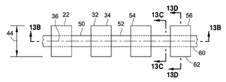
図13Aは、第1の材料60と第2の材料62とからなる繊維22の上面図である。一実施形態では、繊維22の第1の材料60は、繊維22の第1の部分52に含まれている。繊維22の第1の部分は、繊維コア50を含み、繊維22の長手軸36に沿って延びている。繊維22の第2の部分62は、繊維22の一又は複数の第2の部分54に含まれている。一実施形態では、第2の部分54は、繊維コア50の上に取り付けられるか、又は他の方法で配置される。図13Bは、繊維22の長手軸36沿って取った繊維22の断面図である。第1の材料60から形成されて、繊維径46を有する有する繊維コア50が示されている。さらには、第2の材料62から形成されて繊維コア50に取り付けられた複数の第2の部分54が示されている。図13Cは、繊維コア50に沿って取った断面図であり、繊維コア50の第1の断面積38aと、円形に形成された繊維コア50の第1の断面形状40aとを示している。
FIG. 13A is a top view of the
図13Dは、繊維22(図13A)の第2の部分54に沿って取った断面図である。図示の実施形態では、第2の部分54は、正方形に形成された第2の断面形状40bを有している。一実施形態では、第2の部分54の各々は、第2の材料62からなり、繊維コア50に取り付けられた(例えば、接着された)繊維ビーズ56として形成される。図では正方形に示されているが、繊維ビーズ56は様々な断面形状のいずれか一つを有することができる。例えば、繊維ビーズ56は、球、正立方体、直方体、多角形ビーズ、不規則形状のビーズ、概ね円形のビーズ、又は他の様々な大きさ、形状、及び構成のいずれか一つに形成することができる。
FIG. 13D is a cross-sectional view taken along the
図14A〜14Bは、第2の材料62から形成された球形の繊維ビーズ56を有する繊維22の一実施形態を示しており、このビーズ56は、第1の材料60から形成された繊維コア50に取り付けられている。一実施形態では、繊維ビーズ56は、外側の四角形と内側の円形によって画定された斜線部によって表されており、円形内部の斜線部により表される繊維コア50の断面積38より大きな断面積38を有していてよい。
FIGS. 14A-14B illustrate one embodiment of a
有利には、少なくとも二つの異なる材料から繊維22を形成することにより、マトリックス18(図4)に対する繊維22の結合の度合いを調節する追加的手段が提供される。例えば、第1の材料60のマトリックス18との相互作用は、第2の材料62とマトリックス18との相互作用とは異なる。これに関して、第1の材料60は、第1の材料60とマトリックス18との間の結合に異なる特性を生じさせることができる。例えば、第1の材料60は、第1の材料60とマトリックス18との接着結合に、第2の材料62とマトリックス18との接着結合の特性とは異なるレベルの強度、剛性、延性、破断点ひずみ、及び他の特性を付与することができる。
Advantageously, forming the
図15は、繊維長34に沿って半周期的64に変化する繊維形状32を有する繊維22の一実施形態を示している。例えば、繊維22は、繊維長34に沿って間隔を空けて位置する第2の部分54の組を含むことができる。第2の部分54の組は、小さな繊維幅44又は繊維径46を有する繊維22のセクションによって分離されており、ほぼ一定の断面積及び/又はほぼ一定の断面形状を有することができる。第2の部分54には、本明細書に開示される構成のいずれか一つを含む様々に異なる断面形状及び断面積のいずれか一つを付与することができる。有利には、第2の部分54の組は、ほぼ一定の間隔によって分離することができるか、又は二つの第2の部分54の組の間の間隔は可変とすることができる。第2の部分54の大きさと、繊維長34に沿った位置とは、マトリックスに対する繊維22に所望のレベルの機械的連結が提供されるように決めることができる。一実施形態では、第2の部分54は、第2の部分54が取り付けられる小さな径のコア50の材料とは異なる材料から形成される。異なる材料により、繊維22とマトリックス18(図3)との間に異なる相互作用が生じ、繊維22とマトリックス18との間の連結を制御する追加的手段が提供される。
FIG. 15 illustrates one embodiment of a
図15では、繊維形状32の半周期的64な構成は、繊維長34に沿ったマトリックスに対する繊維22の移動を離散的に制御するために調節又は構成可能である。例えば、弾丸の衝撃に起因する複合品10の光学的ひずみの面積を最小化することが望ましい実施形態の場合、第2の部分54の組は、繊維長34に沿って、弾道事象(例えば、弾丸の衝撃)に関与する繊維の範囲を最小化するような間隔で配置することができる。これに関して、第2の部分54の組は、互いに小さな間隔を空けて設けることができる。反対に、弾丸による衝撃の間に複合品10の弾道性能を最大化することが望ましい実施形態の場合、第2の部分54の組は、弾道事象に関与する繊維の範囲を最大化するように、互いに大きな間隔を空けて設けることができる。加えて、第2の部分54の大きさ及び形状は、マトリックスに対する繊維22の移動を離散的に又は定量的に制御するために調節又は構成可能である。
In FIG. 15, the semi-periodic 64 configuration of the
本明細書に開示される実施形態のいずれにおいても、繊維22の断面形状は、様々に異なる構成のいずれか一つとすることができる。例えば、繊維22の断面形状は、円形、閉じた半円、楕円、腎臓の形、三角形、四角形、長方形、多角形、又は様々に異なる断面形状のいずれか一とすることができる。さらに、一実施形態の繊維22は、繊維長に沿って二つ以上の異なる断面形状を含むように構成することができる。加えて、繊維22は、いずれかの不規則な又はランダムな断面形状を有することができ、その形状は既知の幾何学的形状に限定されない。繊維22の一又は複数は、ほぼ空洞の構成を有してもよく、すなわち繊維22は中実の構成に限定されない。繊維22は、随意で、互いにほぼ平行な、少なくとも一対の繊維表面24(図5B、6B、8B、9B、10B)を有する断面形状を含むことができる。加えて、繊維22には、ほぼ平坦な表面と湾曲した表面とを組み合わせた断面形状(図示しない)を付与してもよい。
In any of the embodiments disclosed herein, the cross-sectional shape of the
本明細書に開示される実施形態のいずれにおいても、マトリックス18(図4)及び/又は繊維22(図4)は、限定しないが、任意の適切な有機又は無機材料、熱可塑性プラスチック材料、熱硬化性材料、及び/又はガラス材料から形成することができる。例えば、繊維22に使用可能な種々の材料のいずれか一つを含むマトリックス18及び/又は繊維22は、アクリル、フルオロカーボン、ポリアミド(ナイロン)、ポリエチレン、ポリエステル、ポリプロピレン、ポリカーボネート、ポリウレタン、ポリエーテルエーテルケトン、ポリエーテルケトンケトン、ポリエーテルイミド、延伸ポリマー、及び他のいずれかの適切な熱可塑性プラスチック材料のうちの少なくとも一つを含む熱可塑性プラスチック材料から形成することができる。同様に、繊維22に使用可能な種々の材料のいずれか一つを含むマトリックス18及び/又は繊維22は、ポリウレタン、フェノール樹脂、ポリイミド、ビスマレイミド、ポリエステル、エポキシ、シルセスキオキサン、及び他のいずれかの適切な熱硬化性材料のうちのいずれか一つを含む熱硬化性材料から形成することができる。加えて、マトリックス18及び/又は繊維22は、炭素、炭化ケイ素、ホウ素、又は他の無機材料を含む無機材料から形成することができる。さらには、マトリックス18及び/又は繊維22は、限定しないが、E−glass(アルミニウム−ホウケイ酸ガラス)、S−glass(アルミニウム−ケイ酸塩ガラス)、純シリカ、ホウケイ酸ガラス、光学ガラス、セラミックス、ガラスセラミックス、及び他のいずれかのガラス材料を含むガラスから形成することができる。加えて、マトリックス18及び/又は繊維22は、少なくとも部分的に金属材料から構成されるか、又は金属材料を含む。
In any of the embodiments disclosed herein, the matrix 18 (FIG. 4) and / or the fibers 22 (FIG. 4) are not limited to any suitable organic or inorganic material, thermoplastic material, thermal It can be formed from a curable material and / or a glass material. For example, the
一実施形態では、繊維22(図4)は光学的にほぼ透明な繊維材料から形成されるが、繊維22は実質的に不透明な材料から形成されてもよい。マトリックス18(図4)は、光学的にほぼ透明な高分子材料、又は実質的に不透明な材料から形成することもできる。本明細書に開示される実施形態のいずれにおいても、繊維22は、フィラメントベースの繊維、非フィラメント繊維、ポリ成分繊維、及び他の繊維構成として形成することができる。一実施形態では、繊維22は、約三(3)ミクロン〜5000ミクロンの範囲の繊維厚42、繊維幅44、及び/又は繊維径46を有している。例えば、繊維22は、約三(3)ミクロン〜100ミクロンの範囲の繊維厚42、繊維幅44、及び/又は繊維径46を有することができる。さらなる実施形態では、繊維厚42、繊維幅44、及び/又は繊維径46は、約20ミクロン〜50ミクロンの範囲とすることができる。しかしながら、繊維22には、3ミクロンより小さいか、又は5000ミクロンより大きな繊維厚42、繊維幅44、又は繊維径46を付与することができる。
In one embodiment, the fibers 22 (FIG. 4) are formed from an optically substantially transparent fiber material, although the
複合品10(図4)は、様々に異なる形状、大きさ、及び構成のいずれか一つに構成することができる。これに関して、複合品10は、ビークルに関連する、又はビークルに関連しない任意の用途に使用するために構成することができる。例えば、複合品10は、航空機のようなビークルの透明シートとして構成することができる。複合品10は、航空機の風防、又はキャノピーのいずれかの部分も含むことができる。複合品10は、ビークルに関連する、又はビークルに関連しない用途において窓のいずれかの部分に使用するために構成することもできる。さらには、複合品10は、限定しないが、膜のいずれかの部分、装甲板、構造パネル、建築パネル、非構造パネル又は非構造品、層系、又は複合品10の他の実装態様のいずれかにおいて実施することができるか、或いはそれらに組み込むことができる。
The composite article 10 (FIG. 4) can be configured in any one of a variety of different shapes, sizes, and configurations. In this regard, the
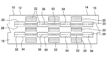
図16は、マトリックス18に埋め込まれた繊維22を有する複合品10の一部を示しており、図中、繊維22は、複数の層20において横並び70の構成に配置されている。各層20内の繊維22は、隣接する層20内の繊維22と直角に方向づけられている。複合品10は、一の層20内の繊維22を、直接隣接する層20内の繊維22に対して相補的に構成することにより、繊維22の係合92を促進する。これに関して、繊維22が、第1の部分52と第2の部分54とを交互に含むように、各繊維22の繊維形状32を繊維長34に沿って変化させることができる。複合品10に対してほぼ直角又は斜めに力90(図16B)を加えると、一の層20内の繊維22の第2の部分54は、直接隣接して位置する層20内の繊維22内部において少なくとも部分的に入れ子になる。
FIG. 16 shows a portion of the
図16Aは図16の複合品の端面図であり、交互になっている層20内の繊維22が、直接隣接する層20内の繊維22の第1の部分52と概ね整列している様子を示している。各層20内の繊維22は、当初、直接隣接する層20内の繊維の一番上の表面又は一番下の表面により規定される面の上方又は下方に配置される。例えば、図16Aの一番上の層20の繊維22の底面は、直接その下に位置する層20の繊維22の一番上の表面により規定される面の上方に位置している。
FIG. 16A is an end view of the composite article of FIG. 16, with the
図16Bは、図16Aの複合品10の端面図であり、繊維22に加わる力90を示している。力90は、複合品10に対する弾丸の衝撃に応答して発生する。図示のように、力90は、層20を互いに接近させ、繊維22を直接隣接する層内の繊維22と係合92させる。これに関して、各層20内の繊維22の第2の部分54は、直接隣接する繊維22の第1の部分52と少なくとも部分的にかみ合うか、又は少なくとも部分的に入れ子74状態になる。繊維22の係合92又は入れ子構成は、比較的大きな量の繊維22が弾道事象に関与するように、弾道事象の間に層20の繊維22を機械的に連結することができる。
FIG. 16B is an end view of the
本明細書に開示される実施形態のいずれにおいても、繊維長34に沿った繊維22の繊維形状34の変化によるマトリックス18と繊維22の機械的連結(例えば、繊維−マトリックス間の連結)は、複合品10の弾道性能及び/又は光学性能を向上させることができる。加えて、同じ層20内における繊維22の機械的な相互連結と、異なる層20内における繊維22の機械的連結と(例えば、面内の繊維−繊維間の連結と、面外の繊維−繊維間の連結)は、複合品10の弾道性能及び/又は光学性能を向上させうる。例えば、複合パネル14のような複合品10が弾丸の衝撃を受ける弾道事象の間に、繊維22が繊維22の長さに沿って長手方向に移動可能であることは、複合パネル14の弾道性能に影響しうる。
In any of the embodiments disclosed herein, the mechanical connection (eg, fiber-matrix connection) between the
上述のように、マトリックス18内で繊維22がマトリックス18に対して繊維長34に沿って長手方向に移動可能であることにより、繊維22が、破壊される前に長手方向に伸張する能力が向上しうる。繊維22の互いに対する移動又はすべりが可能であることによっても、繊維22が長手方向に伸張する能力が向上しうる。繊維22が長手方向に伸張できることにより、複合パネル14との激突の間の、繊維22の弾丸エネルギー吸収能が増大しうる。繊維22のエネルギー吸収能が増大することにより、弾丸112の貫通に対する複合パネル14の耐性が向上して複合パネル14の弾道性能が向上する。
As described above, the ability of the
ほぼ透明な複合パネル14の場合、マトリックス18に対する繊維22の移動と互いに対する繊維22の移動も、弾丸激突後の複合パネル14の光学性能に影響しうる。例えば、繊維22のエネルギー吸収能の増大により、衝撃部位116の周辺領域が縮小しうる(図17。反対に、マトリックス18に対する、及び互いに対する繊維22の移動能を増大させることにより、衝撃後の複合パネル14の光学性能は低下しうる。複合パネル14の衝撃後光学性能の低下は、衝撃部位116の周辺領域の拡大を特徴とする。
In the case of a substantially transparent
図17は、試験品100の正面104に弾丸112が激突する間の試験品100を示す側面図である。試験品100は、複数の繊維110がマトリックス108内に埋め込まれている複合品10の上述の実施形態(図1)と同様に構築されている。上述のように、繊維110は、繊維110の繊維長34(図4)に沿って変化する繊維形状32(図4)を有することができる。正面104に対する弾丸112の衝撃は、物品表面102の激突部位116に生じる。
FIG. 17 is a side view showing the
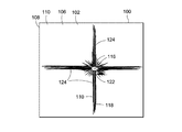
図18は、図17の試験品100の背面106を示しており、図17の試験品の正面104に対する弾丸112の激突に応答して、繊維−マトリックス間の連結、及び/又は繊維−繊維間の連結が比較的小さいことにより、比較的大きな面積にわたって繊維110が局所的及び全体的に影響を受けている様子を示している。図18では、繊維110の局所的関与122には、試験品100の反対側(すなわち、正面104)の、衝撃部位116を直接取り囲む繊維110の部分が含まれる。図示のように、繊維110の全体的関与124は、衝撃部位116を中心に、衝撃部位116から遠ざかる方向に広がっている。試験品100の正面104に対する弾丸112の激突による全体的関与124が比較的大きな範囲にわたっているのは、繊維−マトリックス間の連結及び/又は繊維−繊維間の連結が比較的小さいためである。
FIG. 18 shows the
図19は、試験品の背面図であり、図18に示す実施形態とは対照的に、繊維−マトリックス間の連結、及び/又は繊維−繊維間の連結の量を増大させることにより、繊維の局所的及び全体的関与が比較的小さい様子を示している。図19では、繊維−マトリックス間の連結、及び/又は繊維−繊維間の連結の量の増大は、繊維の繊維長に沿った繊維形状の変化の大きさを増大させることにより達成されている。繊維−マトリックス間の連結、及び/又は繊維−繊維間の連結の増大は、図15に示す半周期的64な構成において、隣接する第2の部分同士の間、又は第2の部分の組同士の間の間隔を小さくすることによって達成してもよい。 FIG. 19 is a rear view of the test article, in contrast to the embodiment shown in FIG. 18, by increasing the amount of fiber-matrix and / or fiber-fiber connections. It shows how local and global involvement is relatively small. In FIG. 19, increasing the amount of fiber-matrix coupling and / or fiber-fiber coupling is achieved by increasing the magnitude of the change in fiber shape along the fiber length of the fiber. The increase in the fiber-matrix connection and / or the fiber-fiber connection can be achieved between the adjacent second portions or between the sets of the second portions in the semi-periodic 64 configuration shown in FIG. It may be achieved by reducing the interval between the two.
図20〜21は、複合品10が、第1の層96及び第2の層98を有する積層形態に取り付けられている層系94の斜視図である。一実施形態では、第1の層96は、セラミック及び/又はガラス材料、或いは他の材料から構成され、層系94の、防弾面(strike face)(図示しない)を含むことができる。第2の層98は、比較的剛性の高い複合層(図示しない)として形成することができ、第1の層96に隣接して取り付けられる。複合品10は、層系94の背面又は後ろ側に位置するように、第2の層98を挟んで第1の層96とは反対側に取り付けられる。
FIGS. 20-21 are perspective views of a
図20〜21は層系94の後ろ側に位置する単一の複合品10を示しているが、任意の数の複合品10が具備されてよい。さらには、図20〜21には単一の第1の層96と単一の第2の層98とが示されているが、任意の数の複合品10と組み合わせて任意の数の第1の層96と第2の層98とが具備されてよい。さらには、層系94は、第1の層96と複合品10だけを含むように形成してもよい。一実施形態では、層系94は装甲パネルを含む。しかしながら、層系94は、限定しないが、任意の物品に組み込むことができ、装甲パネルに限定されない。
20-21 show a single
第1の層96は、セラミック及び/又はガラスからなるモノリシックな層といった、好ましくは比較的高い硬度及び剛性を有する材料から構成することができる。しかしながら、第1の層96は、好ましくは比較的高い剛性及び硬度を有する様々に異なる材料で形成することができる。第1の層96は、弾道的用途に使用される防弾面として機能するように構成することができる。例えば、第1の層96は、弾丸による衝撃を受けるように構成することができる。
The
図20〜21に示すように、第2の層98は第1の層96に隣接して位置することができる。第2の層98は、比較的剛性の高い複合層(図示しない)として形成される。第2の層98は、マトリックス(図示しない)に埋め込まれたガラス繊維(図示しない)を含むことができる。別の構成では、第2の層98は、一又は複数のガラス層又はシート、例えば一又は複数のガラスからなるモノリシックシートで構成される。第2の層98は、少なくとも部分的に、超高比重ポリエチレンといった強度及び/又は剛性の高い高分子材料から形成されて、マトリックス(図示しない)内部に埋め込まれるガラス繊維(図示しない)からなる剛性の高い複合層(図示しない)として形成することもできる。第1の層96、第2の層98、及び複合品10の組み合わせは、共同で、第1の層96の全体的な剛性を高め、層系94の弾道性能を高める補強層系94を形成する。
As shown in FIGS. 20-21, the
図22は、複合品10(図1)の製造方法200において実施される一又は複数の工程を示すフロー図である。方法200のステップ202は、各繊維22(図5A〜13A)が繊維長34(図5A〜13A)と繊維形状32(図5A〜13A)とを有する複数の繊維110(図18)を準備することを含む。
FIG. 22 is a flowchart showing one or a plurality of steps performed in the
ステップ204は、繊維長34(図5A〜14B)に沿って繊維22(図5A〜13A)の繊維形状32(図5A〜14B)を変化させることを含む。例えば、繊維形状32は、繊維長34に沿って第1の部分52(図4)によって分離された一連の第2の部分54(図4)を含むことにより、繊維長34に沿って変形する。一実施形態では、繊維形状32は、繊維長34に沿って周期的58に(図4)変化する。しかしながら、繊維形状32は、半周期的又は非周期的に変化してもよい。
Step 204 includes changing the fiber shape 32 (FIGS. 5A-14B) of the fibers 22 (FIGS. 5A-13A) along the fiber length 34 (FIGS. 5A-14B). For example, the
繊維形状32(図5A〜14B)は、繊維長34(図5A〜14B)に沿って繊維22の断面形状40(図3)を変化させることにより、及び/又は繊維長34に沿って繊維22(図5A〜14B)の断面積38(図3)を変化させることにより、変化させることができる。さらなる実施形態では、繊維形状32は、上述のように、他長手軸36を挟んで交互に繊維22の断面形状40をずらすことにより(図3)、又は繊維長34に沿って断面形状40の方向を変化させることにより、変化させることができる。一実施形態では、繊維22には、蛇行形状78(図8A)、螺旋形状80(図10A)、又は他の形状を付与することができる。繊維22は、上述のように、繊維22とマトリックス18(図3)との間に異なる相互作用を生じさせるために、繊維22とマトリックス18との連結に影響しうる一又は複数の材料から形成することができる。
The fiber shape 32 (FIGS. 5A-14B) is obtained by changing the cross-sectional shape 40 (FIG. 3) of the
方法200のステップ206は、繊維22(図5A〜14B)を横並び70(図3)の構成に配置することにより、層20(例えば、図1〜3、及び14〜14B)を形成することを含む。しかしながら、繊維は、互いに非平行な関係に配置することもできる。さらには、図示しないが、繊維は、互いに様々な角度の一又は複数に方向づけられているとき、織物ファブリックとして供給することができる。一実施形態では、繊維22は、上述のように、第1の部分52(図4)によって相互に結合された一連の第2の部分54(図4)を含むことができる。
Step 206 of
ステップ208は、繊維22の第2の部分54が、層20内の繊維22のうち直接隣接するものの第1の部分52と少なくとも部分的に入れ子74(図4)になるように繊維22を構成することを含む。例えば、図4は、層20内の繊維22の第2の部分54が、層20内で直接隣接する繊維22の第1の部分52と少なくとも部分的に入れ子になるような、層20内の繊維22の配置を示している。図示しない実施形態では、一の層20内の繊維22の第2の部分54は、複合品10の層20のうちの隣接する一の層に含まれる繊維22の第1の部分52と少なくとも部分的に入れ子になるように構成される。
Step 208 configures the
ステップ210は、マトリックス18(図4)に繊維22を埋め込むこと、及びマトリックス18を硬化又は凝固させて複合品10(図4)を形成することを含む。有利には、繊維22の繊維長34に沿った繊維形状32の変化は、弾道事象の間などの相対的な繊維の移動の度合いを調節する手段として、繊維−マトリックス間の機械的連結、及び/又は繊維−繊維間の機械的連結を促進することができる。マトリックスに対する繊維の移動、及び互いに対する繊維の移動の度合いを調節することにより、複合品の弾道性能及び衝撃後光学性能を制御又は改善することができる。
Step 210 includes embedding
一実施形態では、複合品10(図1)は、繊維長34に沿って周期的又は半周期的に変化する繊維形状32を有する繊維22を使用することで、構造性能を向上させるように構成される。例えば、断面積、断面形状、及び/又は方向が長さに沿って変化する繊維22から複合品10を形成することにより、複合品10の損傷許容性及び亀裂成長に対する耐性が、繊維長に沿って形状がほぼ変化しない繊維から形成された従来の複合品の損傷許容性及び亀裂成長に対する耐性と比較して向上する。
In one embodiment, the composite article 10 (FIG. 1) is configured to improve structural performance by using
有利には、本明細書に開示される複合品10(図1)には、繊維長34に沿って繊維形状32が変化することにより、マトリックス18材にいくらかの亀裂の偏向が生じる。これに関して、繊維形状32の変化により、複合品10のマトリックス18に、概ね直線状の経路に沿って伝播するのではなく、ねじれた経路に沿って伝播する亀裂が生じうる。ねじれた経路に沿った伝播は、繊維形状が繊維長に沿ってほぼ変化しない従来の繊維を有する従来の複合品のマトリックスにおける亀裂成長と比較して、マトリックス18内における亀裂成長を抑制できる。このような繊維形状が変化しない従来の繊維には、実質的に連続的な又は一定の断面形状、実質的に連続的な又は一定の断面積、及び/又は実質的に連続的な又は一定の断面形状の方向が含まれる。従来の繊維は、また、繊維長に沿ってほぼ不変の材料種類から形成することができる。
Advantageously, the composite article 10 (FIG. 1) disclosed herein causes some crack deflection in the
一実施形態では、本明細書に開示された複合品10(図1)には、マトリックスの亀裂が一の層20又は複数層20を通るねじれた経路に沿って伝播するように変化する繊維形状32を有する繊維22が含まれる。これに関して、繊維長34に沿った繊維形状の変化は、繊維形状が概ね変化しない従来の繊維を有する従来の複合品と比較して、複合品10の層内(例えば、一の層内部の)靭性及び/又は層間(例えば、隣接する層間の)靭性を高めることができる。層内靭性の向上は、層20内部におけるマトリックスの亀裂の伝播に対する耐性が全体的に増大すること、及び/又は繊維−マトリックス間のインターフェースの剥離部において亀裂伝播に対する耐性が向上することを意味しうる。層間靭性の向上は、隣接層20の層間はく離に対する耐性が全体的に増大することを意味しうる。一実施形態では、繊維22の繊維形状32は、モードI層間破壊靭性を増大させるように、及び/又はモードII層間破壊靭性を増大させるように、変化させることができる。モードI層間破壊靭性は、複合品10の隣接層20にほぼ直角な方向に沿った開離力又は剥離力に対する耐性と特徴づけられる。モードII層間破壊靭性は、複合品10の隣接層20にほぼ平行な剪断力に対する耐性と特徴づけられる。
In one embodiment, the
本明細書に開示される複合品10では、繊維22は、形状の変化によって亀裂成長又は亀裂伝播が抑制される結果、複合品の損傷許容性が向上するように構成される。損傷許容性は、衝撃後圧縮強度及び/又は有孔圧縮強度の上昇として測定することができる。衝撃後圧縮強度の上昇は、複合品に対するオブジェクトの低速度衝撃後の複合品10の残留強度の向上を意味しうる。低速度衝撃の非限定的な例として、ツールを落としたことによる衝撃、又は使用中に複合品10に対して異物が飛んだときの衝撃を挙げることができる。有孔圧縮強度の上昇は、圧縮荷重がかかったときの複合品10の挫屈強度の上昇を意味しうる。
In the
図24は、ビークル(図示しない)などに使用される複合品10(図1)を実装する方法400を示している。複合品10の使用方法400は、上述のようにマトリックス18(図1)に埋め込まれた複数の繊維22(図1)として複合品10を準備するステップ402を含み、これら繊維22の各々は繊維長34(図1)と繊維形状32(図1)とを有し、繊維形状32は繊維長34に沿って変化する。
FIG. 24 illustrates a
図24の方法400は、さらに、複合パネル14(図1)などの複合品10(図1)を、ビークルが実質的に移動していないビークルの第1の状態に置くステップ404を含む。複合パネル14は、静的荷重条件下(図示しない)にあってもよい。一実施形態では、ビークルは、空港ターミナルのゲートに駐機しているときのような、地上にある航空機を含む。図23は、本明細書に開示される複合品10(図1)の一又は複数の実施形態を包含する航空機300の斜視図である。航空機300は、一対の翼304と、垂直安定板312及び水平安定板310を含む尾部308とを有する胴体302を含んでいる。航空機300は、さらに、操縦面306と推進ユニット314とを含む。航空機300は、上述のような複合品の一又は複数を包含しうる様々なビークルの一つを一般的に表している。
The
一実施形態では、複合品10(図1)は、少なくとも部分的に透明で、及び/又は少なくとも部分的に不透明でありうる複合パネル14(図1)を含むことができる。静的荷重条件下では、複合パネル14にかかる荷重は、複合パネル14の質量に作用する重力に起因する荷重に限定される。荷重には、ビークルに対する複合パネル14の取り付けに起因する圧縮荷重も含まれる。静的荷重には、引張荷重、剪断荷重、及び/又は、ビークルに複合パネル14を取り付けたことに起因して、又は隣接する構造の差別的加熱といった他の現象に起因して、又は他の原因に起因して、複合パネル14に作用するねじり荷重が含まれる。
In one embodiment, the composite article 10 (FIG. 1) can include a composite panel 14 (FIG. 1) that can be at least partially transparent and / or at least partially opaque. Under static load conditions, the load applied to the
図24の方法400は、さらに、ビークルが移動中である、及び/又は複合パネル14が動的荷重条件(図示しない)下にある第2の状態に複合パネル14を置くステップ406を含む。例えば、ビークルは、離陸の間に滑走路上で移動中の航空機300(図23)を含む。動的荷重条件下では、複合パネル14にかかる荷重は、圧縮荷重、引張荷重、剪断荷重、及びねじり荷重のいずれか一つ、又はこれらの任意の組み合わせを含みうる。荷重には、弾丸又は飛来する異物による衝撃に起因して複合パネル14上に作用する局所的荷重も含まれる。上述のように、複合パネル14の繊維形状32の長さに沿った変化は、繊維22(図1)とマトリックス18との機械的連結(例えば、繊維−マトリックス間の連結)、及び/又は複合パネル14を形成する層20(図1)のうちの一又は複数内での隣接する繊維22間の機械的連結(例えば、繊維−繊維間の連結)を促進する。機械的連結は、マトリックスに対する繊維の移動、及び/又は繊維間の移動を制御することにより、複合パネル14に激突する弾丸を減速させる能力を増大させる手段となりうる。
The
図24の方法400は、さらに、マトリックス18中に亀裂がある場合に、その亀裂に、複合パネル14中の繊維22の繊維形状32を長方向に沿って変化させることにより得られたねじれた経路(図示しない)を伝播させるステップ408を含む。これに関して、ねじれた経路の方向は、繊維22の繊維形状32の変化によって規定される。亀裂伝播の経路がねじれていることにより、複合パネル14の、層内(例えば、一の層内の)破壊靭性、及び/又は層間(例えば、隣り合う層間の)破壊靭性が向上しうる。これに関して、亀裂がねじれて伝播することにより、航空機300(図23)が離陸又は着陸中に移動している場合に、複合パネル14がツール、滑走路の異物、又は砂利による衝撃といった低速度衝撃をうけたときの複合パネル14の衝撃後圧縮強度が向上しうる。さらには、亀裂がねじれて伝播することにより、圧縮荷重下において、複合パネル14の挫屈強度を上昇させる複合パネル14の有孔圧縮強度が向上しうる。
The
本発明の一態様によれば、マトリックスと、マトリックスに埋め込まれた複数の繊維であって、各々が繊維長と、繊維長に沿って変化する繊維形状とを有する複数の繊維とを備える複合品が提供される。有利には、繊維は第1の材料と第2の材料とからなる。有利には、マトリックス及び繊維の少なくとも一方が、アクリル、ナイロン、フルオロカーボン、ポリアミド、ポリエチレン、ポリエステル、ポリプロピレン、ポリカーボネート、ポリウレタン、ポリエーテルエーテルケトン、ポリエーテルケトンケトン、ポリエーテルイミド、及び延伸ポリマーのうちの少なくとも一つを含む熱可塑性プラスチック材料:ポリウレタン、フェノール樹脂、ポリイミド、ビスマレイミド、ポリエステル、エポキシ、及びシルセスキオキサンのうちの少なくとも一つを含む熱硬化性物質:炭素、炭化ケイ素、ホウ素、並びに、E−glass(アルミニウム−ホウケイ酸ガラス)、S−ガラス(アルミニウム−ケイ酸塩ガラス)、純シリカ、ホウケイ酸ガラス、光学ガラス、セラミックス、及びガラスセラミックスを含むガラスのうちの少なくとも一つを含む無機材料のうちの一つから形成される。有利には、繊維は不透明及び光学的にほぼ透明のうちの少なくとも一方であり、マトリックスは不透明及び光学的にほぼ透明のうちの少なくとも一方である。有利には、複合品は、風防、キャノピー、窓、膜、装甲板、構造パネル、建築パネル、非構造品、及び層系の少なくとも一つに含まれる。有利には、繊維長に沿った繊維形状の変化によりマトリックス中の亀裂がねじれた経路に沿って伝播するように、マトリックス内で繊維が配置され、ねじれた経路により、繊維長に沿って繊維形状がほぼ変化しない繊維を有する複合品のマトリックス中における亀裂成長と比較して、マトリックス中の亀裂成長が抑制される。有利には、ねじれた経路は、少なくとも部分的に、一の繊維層内のマトリックス材、隣り合う層の間のマトリックス材の少なくとも一方の内部に延びる。有利には、繊維の繊維形状は、モードI層間破壊靭性及びモードII層内破壊靭性といった損傷許容性の少なくとも一方を増大させるように変化する。 According to one aspect of the invention, a composite article comprising a matrix and a plurality of fibers embedded in the matrix, each having a fiber length and a fiber shape that varies along the fiber length. Is provided. Advantageously, the fiber consists of a first material and a second material. Advantageously, at least one of the matrix and fibers is selected from the group consisting of acrylic, nylon, fluorocarbon, polyamide, polyethylene, polyester, polypropylene, polycarbonate, polyurethane, polyetheretherketone, polyetherketoneketone, polyetherimide, and stretched polymer. Thermoplastic material including at least one: polyurethane, phenolic resin, polyimide, bismaleimide, polyester, epoxy, and thermosetting material including at least one of silsesquioxane: carbon, silicon carbide, boron, and , E-glass (aluminum-borosilicate glass), S-glass (aluminum-silicate glass), pure silica, borosilicate glass, optical glass, ceramics, and glass ceramic One is formed from one of an inorganic material containing at least one of glass, including a scan. Advantageously, the fibers are at least one of opaque and optically substantially transparent and the matrix is at least one of opaque and optically substantially transparent. Advantageously, the composite article is included in at least one of a windshield, a canopy, a window, a membrane, an armor plate, a structural panel, a building panel, a non-structural article, and a layer system. Advantageously, the fibers are arranged in the matrix such that a crack in the matrix propagates along the twisted path due to changes in the fiber shape along the fiber length, and the twisted path causes the fiber shape along the fiber length. Compared to the crack growth in the matrix of a composite article with fibers with almost no change, crack growth in the matrix is suppressed. Advantageously, the twisted path extends at least partially within at least one of the matrix material in one fiber layer and between the adjacent layers. Advantageously, the fiber shape of the fiber is varied to increase at least one of damage tolerance, such as Mode I interlaminar fracture toughness and Mode II interlaminar fracture toughness.
本発明のまた別の態様によれば、複合日の製造方法が提供され、この方法は、各々が繊維長と繊維形状とを有する複数の繊維であって、繊維の少なくとも一つが繊維長に沿って変化する繊維形状を有する複数の繊維を準備するステップと、マトリックス内に繊維を埋め込むステップとを含む。有利には、繊維の形成には第1の材料と第2の材料とが含まれる。有利には、さらなるステップは、層を形成するために、各々が第1の部分によって分離された一連の第2の部分を有する繊維を横並びの構成に構成することと、層内の繊維の一つの第2の部分が、層内の繊維のうちの直接隣接する一つの第1の部分と少なくとも部分的に入れ子になるように、繊維を配置することとを含む。 According to yet another aspect of the present invention, there is provided a method of manufacturing a composite date, wherein the method is a plurality of fibers each having a fiber length and a fiber shape, at least one of the fibers being along the fiber length. Providing a plurality of fibers having varying fiber shapes and embedding the fibers in a matrix. Advantageously, the fiber formation includes a first material and a second material. Advantageously, the further step consists in configuring the fibers in a side-by-side configuration, each having a series of second parts separated by a first part, to form a layer, and Placing the fibers such that the second portion is at least partially nested with the first portion of one of the fibers in the layer that is immediately adjacent.
本発明のさらなる態様によれば、繊維長と繊維形状とを有し、繊維形状が繊維長の少なくとも一部に沿って変化する、複合品のための繊維が提供される。有利には、繊維形状は、繊維長に沿って可変の断面積を有する。有利には、繊維形状は、繊維長に沿って可変の断面形状を有する。有利には、繊維形状は、繊維長に沿ってほぼ一定の断面積を有する。有利には、繊維は繊維長に沿って延びる長手軸を有し、繊維形状は断面積を有し、断面積は、繊維長に沿った複数の異なる位置において長手軸からずれている。有利には、繊維形状の変化は、繊維長に沿った一連の第1の部分と第2の部分から構成される。有利には、繊維は約3ミクロン〜5000ミクロンの範囲の繊維厚を有している。 According to a further aspect of the invention, there is provided a fiber for a composite article having a fiber length and a fiber shape, wherein the fiber shape varies along at least a portion of the fiber length. Advantageously, the fiber shape has a variable cross-sectional area along the fiber length. Advantageously, the fiber shape has a variable cross-sectional shape along the fiber length. Advantageously, the fiber shape has a substantially constant cross-sectional area along the fiber length. Advantageously, the fibers have a longitudinal axis extending along the fiber length, the fiber shape has a cross-sectional area, and the cross-sectional area is offset from the longitudinal axis at a plurality of different locations along the fiber length. Advantageously, the change in fiber shape consists of a series of first and second portions along the fiber length. Advantageously, the fibers have a fiber thickness in the range of about 3 microns to 5000 microns.
当業者には、本発明の他の修正例及び改良例が明らかであろう。したがって、本明細書に記載及び例示した部品の具体的な組み合わせは、本発明の特定の実施形態を表しているに過ぎず、本発明の精神及び範囲に含まれる別の実施形態又はデバイスを限定するものではない。 Other modifications and improvements of the invention will be apparent to those skilled in the art. Accordingly, the specific combinations of components described and illustrated herein are merely representative of particular embodiments of the invention and are intended to limit other embodiments or devices that fall within the spirit and scope of the invention. Not what you want.
10 複合品
12 複合品の表面
14 複合パネル
16 パネル表面
18 マトリックス
20 層
22 繊維
24 繊維表面
26 繊維の上面
28 繊維の下面
30 繊維の側面
32 繊維形状
34 繊維長
36 長手軸
38 断面積
38a 第1の断面積
38b 第2の断面積
39 繊維長に沿った位置
40 断面形状
40a 第1の断面形状
40b 第2の断面形状
42 繊維厚
44 繊維幅
46 繊維径
48 断面重心
50 繊維コア
52 繊維の第1の部分
54 繊維の第2の部分
56 繊維ビーズ
58 周期的
60 第1の材料
62 第2の材料
64 半周期的
70 横並び
72 空隙
74 入れ子
76 ずれ
78 蛇行形状
80 螺旋形状
81 突出部
82 大きな突出部
83 小さな突出部
84 空洞部
86 短軸
88 長軸
90 力
92 係合
94 層系
96 第1の層
98 第2の層
100 試験品
102 物品表面
104 正面
106 背面
108 マトリックス
110 繊維
112 弾丸
116 激突部位
122 局所的関与
124 全体的関与
300 航空機
302 胴体
304 翼
306 操縦面
308 尾部
310 水平安定板
312 垂直安定板
314 推進ユニット
DESCRIPTION OF
Claims (15)
マトリックス(18)に埋め込まれた複数の繊維(22)であって、
各々が、繊維長(34)と、繊維長(34)に沿って変化する繊維形状(32)とを有する繊維(22)と
を備える複合品。 Matrix (18);
A plurality of fibers (22) embedded in a matrix (18),
A composite article comprising a fiber (22), each having a fiber length (34) and a fiber shape (32) that varies along the fiber length (34).
断面積が繊維長(34)に沿って可変である、
請求項1に記載の複合品。 The fiber shape (32) has a cross-sectional area, and the cross-sectional area is variable along the fiber length (34);
The composite article according to claim 1.
断面形状が繊維長(34)に沿って可変である、
請求項1又は2に記載の複合品。 The fiber shape (32) has a cross-sectional shape, and the cross-sectional shape is variable along the fiber length (34);
The composite article according to claim 1 or 2.
繊維形状(32)が断面積を有し、且つ
断面積が繊維長(34)に沿った異なる位置において長手軸からずれている、
請求項1ないし3のいずれか一項に記載の複合品。 The fiber (22) has a longitudinal axis extending along the fiber length (34);
The fiber shape (32) has a cross-sectional area, and the cross-sectional area is offset from the longitudinal axis at different positions along the fiber length (34);
The composite article according to any one of claims 1 to 3.
長軸が、繊維長(34)に沿って変化する方向を有している、
請求項1ないし4のいずれか一項に記載の複合品。 The fiber shape (32) has a cross-sectional shape with a major axis, and the major axis has a direction that varies along the fiber length (34),
The composite article according to any one of claims 1 to 4.
層(20)内の繊維(22)の少なくとも一部が、一連の第1の部分と第2の部分とからなっており、且つ
繊維(22)の一つの第2の部分が、層(20)内の繊維(22)のうち直接隣接する繊維の第1の部分と少なくとも部分的に入れ子になるように、繊維(22)が構成されている、
請求項1ないし5のいずれか一項に記載の複合品。 The fibers (22) are arranged in a side-by-side configuration to form a layer (20);
At least a portion of the fibers (22) in the layer (20) consist of a series of first and second portions, and one second portion of the fibers (22) is the layer (20 The fibers (22) are configured to be at least partially nested with the first portion of the fibers (22) directly adjacent within
The composite article according to any one of claims 1 to 5.
マトリックス(18)が、不透明及び光学的に実質的に透明のうちの少なくとも一方である、
請求項1ないし6のいずれか一項に記載の複合品。 The fibers (22) are at least one of opaque and optically substantially transparent, and the matrix (18) is at least one of opaque and optically substantially transparent;
The composite article according to any one of claims 1 to 6.
各々が繊維長(34)と繊維形状(32)とを有する複数の繊維(22)を準備するステップであって、繊維(22)の少なくとも一つが、繊維長(34)に沿って変化する繊維形状(32)を有するステップと、
マトリックス(18)に繊維(22)を埋め込むステップと
を含む方法。 A method of manufacturing a composite product,
Preparing a plurality of fibers (22) each having a fiber length (34) and a fiber shape (32), wherein at least one of the fibers (22) varies along the fiber length (34) Having a shape (32);
Embedding fibers (22) in a matrix (18).
繊維長(34)に沿って繊維(22)の断面形状を変化させるステップ
を含む請求項8に記載の方法。 further,
The method of claim 8, comprising changing the cross-sectional shape of the fiber (22) along the fiber length (34).
繊維長(34)に沿って繊維(22)の断面積を変化させるステップ
を含む請求項8又は9に記載の方法。 further,
10. A method according to claim 8 or 9, comprising the step of varying the cross-sectional area of the fiber (22) along the fiber length (34).
繊維(22)の長手軸から繊維(22)の断面形状をずらすステップ
を含む請求項8ないし10のいずれか一項に記載の方法。 further,
11. A method according to any one of claims 8 to 10, comprising the step of shifting the cross-sectional shape of the fiber (22) from the longitudinal axis of the fiber (22).
繊維(22)を横並びの構成に構成して層(20)を形成するステップであって、繊維(22)の各々が、第1の部分によって分離された一連の第2の部分を有するステップと、
層(20)内の繊維(22)の一つの第2の部分が、層(20)内の繊維(22)のうち直接隣接する繊維の第1の部分と少なくとも部分的に入れ子になるように、繊維(22)を配置するステップと
を含む請求項8ないし11のいずれか一項に記載の複合品。 further,
Configuring the fibers (22) in a side-by-side configuration to form a layer (20), each of the fibers (22) having a series of second portions separated by a first portion; ,
One second portion of the fibers (22) in the layer (20) is at least partially nested with the first portion of the fibers (22) in the layer (20) that are directly adjacent. A composite article according to any one of claims 8 to 11, comprising the step of arranging fibers (22).
マトリックス(18)に埋め込まれた複数の繊維(22)として複合品(10)を準備するステップであって、繊維(22)の各々が、繊維長(34)と、繊維長(34)に沿って変化する繊維形状(32)とを有するステップと、
複合品(10)を、静的荷重条件を満たす第1の状態におくステップと、
複合品(10)を、動的荷重条件を満たす第2の状態におくステップと、
を含む方法。 A method of applying a load to a composite product of a vehicle,
Preparing a composite article (10) as a plurality of fibers (22) embedded in a matrix (18), each of the fibers (22) extending along a fiber length (34) and a fiber length (34); And changing fiber shape (32)
Placing the composite article (10) in a first state satisfying a static load condition;
Placing the composite article (10) in a second state satisfying a dynamic load condition;
Including methods.
繊維長(34)に沿って変化する繊維形状(32)により、マトリックス(18)中の亀裂を、ねじれた経路に沿って伝播させるステップ
を含む請求項13に記載の方法。 further,
14. The method of claim 13, comprising the step of propagating cracks in the matrix (18) along a twisted path with a fiber shape (32) that varies along the fiber length (34).
動的荷重条件が、移動中のビークルに関連付けられる、
請求項13又は14に記載の方法。 A static load condition is associated with the vehicle that is not substantially moving, and a dynamic load condition is associated with the moving vehicle.
15. A method according to claim 13 or 14.
Applications Claiming Priority (2)
| Application Number | Priority Date | Filing Date | Title |
|---|---|---|---|
| US13/450,823 | 2012-04-19 | ||
| US13/450,823 US8790777B2 (en) | 2012-04-19 | 2012-04-19 | Composite articles having fibers with longitudinally-varying geometry |
Related Parent Applications (1)
| Application Number | Title | Priority Date | Filing Date |
|---|---|---|---|
| JP2013086429A Division JP6196461B2 (en) | 2012-04-19 | 2013-04-17 | Composite product having fibers whose shape is variable in the longitudinal direction |
Publications (2)
| Publication Number | Publication Date |
|---|---|
| JP2017193715A true JP2017193715A (en) | 2017-10-26 |
| JP6510585B2 JP6510585B2 (en) | 2019-05-08 |
Family
ID=48128178
Family Applications (2)
| Application Number | Title | Priority Date | Filing Date |
|---|---|---|---|
| JP2013086429A Active JP6196461B2 (en) | 2012-04-19 | 2013-04-17 | Composite product having fibers whose shape is variable in the longitudinal direction |
| JP2017100624A Active JP6510585B2 (en) | 2012-04-19 | 2017-05-22 | Composite article with fibers whose shape is variable in the longitudinal direction |
Family Applications Before (1)
| Application Number | Title | Priority Date | Filing Date |
|---|---|---|---|
| JP2013086429A Active JP6196461B2 (en) | 2012-04-19 | 2013-04-17 | Composite product having fibers whose shape is variable in the longitudinal direction |
Country Status (9)
| Country | Link |
|---|---|
| US (1) | US8790777B2 (en) |
| EP (3) | EP3406426A1 (en) |
| JP (2) | JP6196461B2 (en) |
| KR (1) | KR101975064B1 (en) |
| CN (2) | CN105965906B (en) |
| AU (2) | AU2016203503B2 (en) |
| CA (1) | CA2804844C (en) |
| ES (1) | ES2701416T3 (en) |
| RU (3) | RU2758653C2 (en) |
Families Citing this family (15)
| Publication number | Priority date | Publication date | Assignee | Title |
|---|---|---|---|---|
| US10005256B2 (en) * | 2012-06-14 | 2018-06-26 | The Boeing Company | Selectively weakened stretched films |
| US9452587B2 (en) * | 2012-08-06 | 2016-09-27 | The Regents Of The University Of California | Shock and impact resistant materials |
| US20140357761A1 (en) * | 2013-06-04 | 2014-12-04 | James Kelly Williamson | Carbon fiber tubule rod reinforced concrete |
| US9242079B2 (en) * | 2013-11-12 | 2016-01-26 | Gyrus Acmi, Inc. | Ureteral stents with waveform interlayers and interstitching |
| EP3023669B1 (en) * | 2014-11-20 | 2020-12-30 | Airbus (Sas) | Device for absorbing kinetic energy and aircraft comprising such a device |
| US9821530B2 (en) | 2014-11-25 | 2017-11-21 | The Boeing Company | Composite laminate including interlayers with through-plane regions fused to fiber beds |
| JP5880671B1 (en) * | 2014-11-28 | 2016-03-09 | 株式会社豊田自動織機 | Shock absorber and method for producing shock absorber |
| CN106747533B (en) * | 2016-06-13 | 2017-12-19 | 北京航空航天大学 | A kind of fiber architecture mode for improving numbers of hot-side engine component ceramic matric composite mechanical property |
| CN108046797A (en) * | 2017-11-30 | 2018-05-18 | 华中科技大学 | It is a kind of to utilize preparation method of crystal whisker toughened zirconium oxide thin plate and products thereof |
| CN108309424A (en) * | 2018-01-18 | 2018-07-24 | 江苏百易得医疗科技有限公司 | A kind of distal radial palmar lockplate |
| CN109610045B (en) * | 2018-08-23 | 2021-09-21 | 成都市宏智达科技有限公司 | Preparation method of high-temperature-resistant and high-strength silicon carbide fiber |
| US11446884B2 (en) * | 2018-10-29 | 2022-09-20 | Airbus Operations Gmbh | Process for producing a component which is two-dimensional in regions from a fibre composite material |
| CN110230952A (en) * | 2019-05-20 | 2019-09-13 | 大连金玛硼业科技集团股份有限公司 | A kind of structure and ceramics pretreating process of monoblock type boron carbide bulletproof plate |
| CN110627379A (en) * | 2019-10-28 | 2019-12-31 | 河南交通职业技术学院 | Preparation method of basalt fiber swab for concrete |
| CN113028901A (en) * | 2021-03-22 | 2021-06-25 | 苏州第一元素纳米技术有限公司 | Bulletproof composite armor and preparation method thereof |
Citations (8)
| Publication number | Priority date | Publication date | Assignee | Title |
|---|---|---|---|---|
| JP2000037790A (en) * | 1998-07-21 | 2000-02-08 | Bridgestone Corp | Band element for pneumatic tire and manufacture thereof |
| US6060163A (en) * | 1996-09-05 | 2000-05-09 | The Regents Of The University Of Michigan | Optimized geometries of fiber reinforcement of cement, ceramic and polymeric based composites |
| US6340522B1 (en) * | 2000-07-13 | 2002-01-22 | Wr Grace & Co.-Conn. | Three-dimensional twisted fibers and processes for making same |
| US20020037409A1 (en) * | 2000-09-06 | 2002-03-28 | George Tunis | Wire reinforced thermoplastic coating |
| JP2005022396A (en) * | 2002-11-14 | 2005-01-27 | Toray Ind Inc | Reinforced fiber base material, composite material and their manufacturing method |
| JP2007296721A (en) * | 2006-04-28 | 2007-11-15 | Kobe Steel Ltd | Apparatus for manufacturing filament-reinforced resin strand |
| US20110003150A1 (en) * | 2008-02-28 | 2011-01-06 | Measom Ronald J | Uncured Composite Rope Including a Plurality of Different Fiber Materials |
| JP2011062007A (en) * | 2009-09-11 | 2011-03-24 | Toshiba Corp | Transformer protection system and device for the same |
Family Cites Families (21)
| Publication number | Priority date | Publication date | Assignee | Title |
|---|---|---|---|---|
| JPS5042151Y1 (en) * | 1970-04-25 | 1975-11-29 | ||
| FR2623786B1 (en) * | 1987-11-30 | 1990-03-23 | Michelin & Cie | DEVICE AND METHOD FOR APPLYING WIRES ON A SUPPORT IN PARTICULAR IN A SINUOUS FORM |
| DE68925259T2 (en) | 1988-10-05 | 1996-09-19 | Asahi Chemical Ind | Viscose fiber with an excellent appearance |
| CA2011515C (en) | 1990-03-05 | 1994-10-11 | Roger Boulanger | Method for producing a non-woven fabric with a thermally activated adhesive surface, resulting product and applications thereof |
| US5888609A (en) * | 1990-12-18 | 1999-03-30 | Valtion Teknillinen Tutkimuskeskus | Planar porous composite structure and method for its manufacture |
| DE4226744A1 (en) * | 1992-08-13 | 1994-02-17 | Vulkan Harex Stahlfasertech | Fiber for reinforcing concrete or the like from wire or flat ribbon and device for producing such fibers |
| US5665450A (en) * | 1992-08-21 | 1997-09-09 | The Curators Of The University Of Missouri | Optically transparent composite material and process for preparing same |
| JPH08218220A (en) * | 1995-02-15 | 1996-08-27 | Kuraray Co Ltd | Thick fiber suitable for reinforcing |
| US6454989B1 (en) | 1998-11-12 | 2002-09-24 | Kimberly-Clark Worldwide, Inc. | Process of making a crimped multicomponent fiber web |
| FR2792950B1 (en) * | 1999-04-27 | 2006-07-28 | Max Sardou | FIBER COMPOSITE MATERIALS OPTIMIZED TO INCREASE SERVICE CONSTRAINTS AND FATIGUE |
| AU2001229311A1 (en) * | 2000-01-13 | 2001-07-24 | The Dow Chemical Company | Small cross-section composites of longitudinally oriented fibers and a thermoplastic resin as concrete reinforcement |
| US7261945B2 (en) * | 2003-04-28 | 2007-08-28 | The Johns Hopkins University | Impact resistant flexible body device |
| US7786026B2 (en) * | 2003-12-19 | 2010-08-31 | Saint-Gobain Technical Fabrics America, Inc. | Enhanced thickness fabric and method of making same |
| US20050227564A1 (en) | 2004-01-30 | 2005-10-13 | Bond Eric B | Shaped fiber fabrics |
| NL2000232C2 (en) * | 2006-09-12 | 2008-03-13 | Gtm Consulting B V | Skin panel for an aircraft fuselage. |
| DE102007019716A1 (en) * | 2007-04-26 | 2008-10-30 | Airbus Deutschland Gmbh | Fiber metal laminate panel |
| JP5328401B2 (en) * | 2009-02-10 | 2013-10-30 | 本田技研工業株式会社 | Shock absorbing member |
| CN101524903A (en) * | 2009-04-09 | 2009-09-09 | 哈尔滨工业大学 | Carbon fiber metal laminate |
| EP2405670B1 (en) | 2010-07-08 | 2012-09-12 | Harman Becker Automotive Systems GmbH | Vehicle audio system with headrest incorporated loudspeakers |
| US8559779B2 (en) | 2010-10-08 | 2013-10-15 | The Boeing Company | Transparent composites with organic fiber |
| US8530027B2 (en) * | 2010-12-15 | 2013-09-10 | The Boeing Company | Fibers with interlocking shapes |
-
2012
- 2012-04-19 US US13/450,823 patent/US8790777B2/en active Active
-
2013
- 2013-02-05 CA CA2804844A patent/CA2804844C/en active Active
- 2013-02-25 KR KR1020130019952A patent/KR101975064B1/en active IP Right Grant
- 2013-03-28 CN CN201610281660.0A patent/CN105965906B/en active Active
- 2013-03-28 CN CN201310104995.1A patent/CN103373011B/en active Active
- 2013-04-15 RU RU2017143924A patent/RU2758653C2/en active
- 2013-04-15 RU RU2017143925A patent/RU2760022C2/en active
- 2013-04-15 RU RU2013117042A patent/RU2640061C2/en active
- 2013-04-17 JP JP2013086429A patent/JP6196461B2/en active Active
- 2013-04-17 EP EP18183002.7A patent/EP3406426A1/en active Pending
- 2013-04-17 ES ES13164189T patent/ES2701416T3/en active Active
- 2013-04-17 EP EP13164189.6A patent/EP2653293B1/en active Active
- 2013-04-17 EP EP18183003.5A patent/EP3406427A1/en active Pending
-
2016
- 2016-05-27 AU AU2016203503A patent/AU2016203503B2/en active Active
-
2017
- 2017-05-22 JP JP2017100624A patent/JP6510585B2/en active Active
- 2017-06-28 AU AU2017204407A patent/AU2017204407B2/en active Active
Patent Citations (8)
| Publication number | Priority date | Publication date | Assignee | Title |
|---|---|---|---|---|
| US6060163A (en) * | 1996-09-05 | 2000-05-09 | The Regents Of The University Of Michigan | Optimized geometries of fiber reinforcement of cement, ceramic and polymeric based composites |
| JP2000037790A (en) * | 1998-07-21 | 2000-02-08 | Bridgestone Corp | Band element for pneumatic tire and manufacture thereof |
| US6340522B1 (en) * | 2000-07-13 | 2002-01-22 | Wr Grace & Co.-Conn. | Three-dimensional twisted fibers and processes for making same |
| US20020037409A1 (en) * | 2000-09-06 | 2002-03-28 | George Tunis | Wire reinforced thermoplastic coating |
| JP2005022396A (en) * | 2002-11-14 | 2005-01-27 | Toray Ind Inc | Reinforced fiber base material, composite material and their manufacturing method |
| JP2007296721A (en) * | 2006-04-28 | 2007-11-15 | Kobe Steel Ltd | Apparatus for manufacturing filament-reinforced resin strand |
| US20110003150A1 (en) * | 2008-02-28 | 2011-01-06 | Measom Ronald J | Uncured Composite Rope Including a Plurality of Different Fiber Materials |
| JP2011062007A (en) * | 2009-09-11 | 2011-03-24 | Toshiba Corp | Transformer protection system and device for the same |
Also Published As
| Publication number | Publication date |
|---|---|
| CN105965906B (en) | 2018-10-26 |
| EP2653293A1 (en) | 2013-10-23 |
| AU2016203503A1 (en) | 2016-06-16 |
| CA2804844A1 (en) | 2013-10-19 |
| CN103373011B (en) | 2016-05-11 |
| KR101975064B1 (en) | 2019-05-03 |
| KR20130118231A (en) | 2013-10-29 |
| RU2013117042A (en) | 2014-10-20 |
| AU2017204407B2 (en) | 2018-04-26 |
| RU2017143925A3 (en) | 2021-03-15 |
| US8790777B2 (en) | 2014-07-29 |
| RU2760022C2 (en) | 2021-11-22 |
| EP3406427A1 (en) | 2018-11-28 |
| RU2017143924A3 (en) | 2021-04-02 |
| RU2017143924A (en) | 2019-02-14 |
| EP3406426A1 (en) | 2018-11-28 |
| ES2701416T3 (en) | 2019-02-22 |
| RU2758653C2 (en) | 2021-11-01 |
| AU2013200649A1 (en) | 2013-11-07 |
| CN105965906A (en) | 2016-09-28 |
| CN103373011A (en) | 2013-10-30 |
| AU2016203503B2 (en) | 2017-06-15 |
| EP2653293B1 (en) | 2018-09-12 |
| RU2017143925A (en) | 2019-06-14 |
| JP2013224816A (en) | 2013-10-31 |
| CA2804844C (en) | 2021-01-12 |
| JP6196461B2 (en) | 2017-09-13 |
| RU2640061C2 (en) | 2017-12-26 |
| US20130280516A1 (en) | 2013-10-24 |
| AU2017204407A1 (en) | 2017-07-20 |
| JP6510585B2 (en) | 2019-05-08 |
Similar Documents
| Publication | Publication Date | Title |
|---|---|---|
| JP6196461B2 (en) | Composite product having fibers whose shape is variable in the longitudinal direction | |
| EP2652432B1 (en) | Controlled fiber-matrix adhesion for polymer fiber composites | |
| EP2651625B1 (en) | Composite material comprising fibers with interlocking shapes, and method to manufacture it | |
| EP3257670A1 (en) | Selectively coupled fibers in composites |
Legal Events
| Date | Code | Title | Description |
|---|---|---|---|
| A131 | Notification of reasons for refusal |
Free format text: JAPANESE INTERMEDIATE CODE: A131 Effective date: 20180703 |
|
| A521 | Request for written amendment filed |
Free format text: JAPANESE INTERMEDIATE CODE: A523 Effective date: 20181002 |
|
| TRDD | Decision of grant or rejection written | ||
| A01 | Written decision to grant a patent or to grant a registration (utility model) |
Free format text: JAPANESE INTERMEDIATE CODE: A01 Effective date: 20190312 |
|
| A61 | First payment of annual fees (during grant procedure) |
Free format text: JAPANESE INTERMEDIATE CODE: A61 Effective date: 20190404 |
|
| R150 | Certificate of patent or registration of utility model |
Ref document number: 6510585 Country of ref document: JP Free format text: JAPANESE INTERMEDIATE CODE: R150 |
|
| R250 | Receipt of annual fees |
Free format text: JAPANESE INTERMEDIATE CODE: R250 |
|
| R250 | Receipt of annual fees |
Free format text: JAPANESE INTERMEDIATE CODE: R250 |
|
| R250 | Receipt of annual fees |
Free format text: JAPANESE INTERMEDIATE CODE: R250 |