JP2017193396A - Spiral coil laminate and stacked body of spiral coil laminate - Google Patents
Spiral coil laminate and stacked body of spiral coil laminate Download PDFInfo
- Publication number
- JP2017193396A JP2017193396A JP2016083731A JP2016083731A JP2017193396A JP 2017193396 A JP2017193396 A JP 2017193396A JP 2016083731 A JP2016083731 A JP 2016083731A JP 2016083731 A JP2016083731 A JP 2016083731A JP 2017193396 A JP2017193396 A JP 2017193396A
- Authority
- JP
- Japan
- Prior art keywords
- spiral coil
- layer
- copper
- coil
- copper tube
- Prior art date
- Legal status (The legal status is an assumption and is not a legal conclusion. Google has not performed a legal analysis and makes no representation as to the accuracy of the status listed.)
- Pending
Links
Images


Landscapes
- Winding Filamentary Materials (AREA)
Abstract
Description
本発明は、エアコン、エコキュートなどのクロスフィン型熱交換器の伝熱銅管として用いられる銅管が巻き回されている積層コイルに関する。 The present invention relates to a laminated coil around which a copper tube used as a heat transfer copper tube of a cross fin type heat exchanger such as an air conditioner or an ecocute is wound.
従来より、ルームエアコン、パッケージエアコンなどの空調機用熱交換器、冷凍機等の伝熱管又は冷媒配管には、銅管が用いられてきたが、これらの銅管は、銅又は銅合金から所定の加工が施された後、コイル状に巻かれ、次いで、焼鈍等の熱処理が施された後、エアコンメーカー等に搬送される。そして、コイル状に巻かれた銅管は、エアコンメーカーで巻き解かれ、それぞれの用途に応じた形状に加工されて使用される。 Conventionally, copper pipes have been used for heat transfer pipes or refrigerant pipes for air conditioners such as room air conditioners and packaged air conditioners, and refrigerators. These copper pipes are made of copper or copper alloy. After being processed, it is wound in a coil shape, and then subjected to a heat treatment such as annealing, and then conveyed to an air conditioner manufacturer or the like. And the copper pipe wound by the coil shape is unwound by an air-conditioner maker, and is processed and used for the shape according to each use.
コイル状に巻かれた銅管としては、レベルワウンドコイルが一般的である。このレベルワウンドコイルは、銅管をボビンにコイル状に整列巻し、それを多数積層させることにより作製される。具体的には、例えば、図12〜図14に示すように、先ず、銅管22が、コイルからの取り外し可能なボビン21の内筒24の周りに端から他端まで(図13中、符号25で示す矢印の方向)、コイルの中心軸の延長方向に整列巻されて、一層目の整列巻きコイル23aが形成され、次いで、一層目の上に、一層目とは反対の方向(図13中、符号26で示す矢印の方向)に、銅管が整列巻されて、二層目の整列巻きコイル23bが形成される。そして、これが繰り返されて、銅管が整列巻きされている整列巻きコイルが、コイルの中心軸に対し垂直な方向に多層積層されているレベルワウンドコイル21が作製される。
As the copper tube wound in a coil shape, a level-wound coil is generally used. This level-wound coil is produced by aligning and winding a copper tube around a bobbin in a coil shape and laminating a number of them. Specifically, for example, as shown in FIGS. 12 to 14, first, the
そして、作製されたレベルワウンドコイル20は、図14に示すように、コイルの中心軸の延長方向が垂直方向になるように、敷板16上に置かれて、エアコンメーカー等に搬送され、エアコンメーカー等で、レベルワウンドコイルの内側から、銅管22が繰り出されて、コイルが巻き解かれる。図15に示すように、レベルワウンドコイル20が、コイルの中心軸の延長方向33が垂直方向になるように置かれると、レベルワウンドコイル20には、上から下に向かって順に巻き解かれる整列巻きコイル23aと、反対に、下から上に向かって順に巻き解かれる整列巻きコイル23bとが、交互に存在する。そして、コイルの巻き解き時において、上から下に向かって順に巻き解かれる整列巻きコイル23aが、一番下の銅管22aまで巻き解かれたら、次は、一つ外側の整列巻きコイル23bが、今度は、下から上に向かって順に巻き解かれることになる。下から上に向かって順に巻き解かれる整列巻きコイル23bの一番下の銅管22bには、その層の全銅管の重さがかかっているため、一番下の銅管22bが敷板16に接していたのでは、一番下の銅管22bが敷板16と上にある銅管との間に挟まって、銅管22bの繰り出しができなくなる。
Then, as shown in FIG. 14, the produced level wound coil 20 is placed on the
そこで、特開2002−370869号公報(特許文献1)には、図16に示すように、コイルの中心軸の延長方向が垂直方向になるように置いた時に、下から上に向かって順に巻き解かれることとなる整列巻きコイル27bについては、上から下に向かって順に巻き解かれることとなる整列巻きコイル27aよりも上方に引き上げて、整列巻きコイル27bの一番下の銅管22bの下と敷板16との間に隙間を形成させることにより、一番下の銅管22bが敷板16と上にある銅管との間に挟まるのを防ぐレベルワウンドコイル(いわいる段落ちコイル)が開示されている。この段落ちコイルでは、上から下に向かって順に巻き解かれることとなる整列巻きコイルの一番下の銅管と敷板との間に形成される隙間の大きさは、銅管の銅管径の半分程度に設定される。
Therefore, in Japanese Patent Application Laid-Open No. 2002-370869 (Patent Document 1), as shown in FIG. 16, when the extension direction of the central axis of the coil is placed in the vertical direction, winding is performed in order from the bottom to the top. The aligned
レベルワンドコイルが上に置かれる敷板は、運搬時にコイルの一番下の銅管が潰れないように、ある程度柔らかい材質でなければならない。そのため、特許文献1の段落ちレベルワウンドコイルでは、上から下に向かって順に巻き解かれることとなる整列巻きコイルの一番下の銅管は、敷板にある程度めり込むことになる。
The floorboard on which the level wand coil is placed must be made of a material that is soft to some extent so that the copper pipe at the bottom of the coil is not crushed during transportation. Therefore, in the step-down level wound coil of
そして、上から下に向かって順に巻き解かれることとなる整列巻きコイルの一番下の銅管の敷板へのめり込みが大きくなり過ぎると、下から上に向かって順に巻き解かれることとなる整列巻きコイルの一番下の銅管までもが、敷板に接触してしまい、一番下の銅管が繰り出されるときに、敷板により抵抗を受けて、一番下の銅管に余分な力がかってしまう。そのため、そのことが、銅管の折れを発生させてしまい、繰り出しトラブルの原因になるという問題があった。特に、銅管の径が小さくなる程、特に銅管径が5mm以下になると、下から上に向かって順に巻き解かれることとなる整列巻きコイルの一番下の銅管と敷板との間の隙間が小さくなるため、このような銅管の繰り出しトラブルの問題が起こり易い。 And if the amount of squeezing into the bottom copper tube base plate of the aligned winding coil that will be unwound in order from the top to the bottom becomes too large, the aligned winding will be unwound in order from the bottom to the top. Even the bottom copper tube of the coil comes into contact with the bottom plate, and when the bottom copper tube is drawn out, resistance is received by the bottom plate, and extra force is applied to the bottom copper tube. End up. For this reason, there is a problem in that this causes breakage of the copper tube and causes a feeding trouble. In particular, the smaller the diameter of the copper tube, especially when the diameter of the copper tube is 5 mm or less, between the bottom copper tube and the bottom plate of the aligned winding coil that will be unwound in order from the bottom to the top. Since the gap becomes small, such a problem of copper pipe feeding trouble is likely to occur.
また、図16に示すような段落ちレベルワウンドコイルでは、銅管は、他の銅管と重なりが密であるため、最終熱処理時に、銅管同士の溶着による貼り付きが起こった場合、線状に長く貼り付きが起こる。そのため、銅管を繰り出す時に、銅管が剥がれ難くなり、それが銅管の折れを発生させてしまい、繰り出しトラブルの原因となるという問題があった。 Further, in the stepped level wound coil as shown in FIG. 16, since the copper tube is densely overlapped with other copper tubes, when sticking occurs due to welding of the copper tubes during the final heat treatment, Long sticking occurs. For this reason, when the copper tube is fed out, the copper tube is difficult to peel off, which causes the copper tube to be broken, which causes a feeding trouble.
また、σ0.2が70MPa未満の純銅軟質材からなる銅管では、銅管が巻き解かれる際、上方に繰り出された銅管が、下方の巻き解かれた銅管の自重により直状に整直され、コイルの巻き径が小さくなり、コイルの中心軸の方へ引き寄せられることで、銅管がコイルの巻列より離れるため、未だ巻き解かれていないコイルの内側の銅管に引っ掛かること無く繰り出される。それに対して、σ0.2が70MPa以上の高強度銅からなる銅管では、この自重による整直が生じ難いため、下方の巻き解かれた銅管が巻き曲率を保ったまま、バネ状の螺旋管となって上方に繰り出されることになる。そのため、繰り出し時に、未だ巻き解かれていないコイルの内側の銅管に、曲率を保ったままの巻き解かれた銅管が引っ掛かる繰り出しトラブルが生じ易い。 In addition, in a copper pipe made of a pure copper soft material having a σ0.2 of less than 70 MPa, when the copper pipe is unwound, the copper pipe fed upward is straightened by the weight of the lower unrolled copper pipe. Because the coil diameter is reduced and the coil winding diameter is reduced and pulled toward the central axis of the coil, the copper pipe is separated from the coil winding line, so that it is not caught by the copper pipe inside the coil that has not yet been unwound. It is paid out. On the other hand, in a copper tube made of high-strength copper having a σ0.2 of 70 MPa or more, it is difficult for this self-weight to cause straightening. Therefore, the unrolled copper tube below has a spring-like spiral while maintaining the winding curvature. It becomes a pipe and is fed upward. Therefore, at the time of unwinding, the unrolled copper tube that is not yet unrolled easily catches unrolled copper tube with its curvature maintained.
また、高強度銅からなる銅管では、最終熱処理温度が高いため、熱処理時の銅管同士の融着による貼り付きが生じ易くなるので、貼り付きが原因の繰り出しトラブルが起こり易い。 In addition, since the final heat treatment temperature is high in a copper tube made of high-strength copper, sticking due to fusion of the copper tubes during heat treatment is likely to occur, so that a feeding trouble due to sticking is likely to occur.
従って、本発明の目的は、かかる従来の問題点を解決することであり、多層に巻かれたコイルから銅管を繰り出す時に、上記のような銅管の繰り出しトラブルの問題が生じ難い高強度銅からなる銅管の多層コイルを提供することにある。 Accordingly, an object of the present invention is to solve such a conventional problem, and when a copper tube is drawn out from a coil wound in multiple layers, the problem of the above-mentioned copper tube drawing trouble is unlikely to occur. It is providing the multilayer coil of the copper pipe which consists of these.
上記課題は、以下に示す本発明により解決される。
すなわち、本発明(1)は、銅管が渦巻き状に巻かれている渦巻きコイルが、コイル積層体の中心軸の延長方向に、多数積層されているコイル積層体であり、
最も内側が1つ上の層の渦巻きコイルの最も内側と繋がり且つ最も外側が1つ下の層の渦巻きコイルの最も外側に繋がるA層渦巻きコイルと、最も外側が1つ上の層の渦巻きコイルの最も外側と繋がり且つ最も内側が1つ下の層の渦巻きコイルの最も内側に繋がるB層渦巻きコイルと、からなり、
該A層渦巻きコイルと該B層渦巻きコイルとが交互に繰り返されており、
各層の該渦巻きコイルの銅管は、曲率半径が連続して変化し、且つ、隣り合う銅管同士の隙間が銅管径より小さくなるように巻かれており、
該銅管は、Cu含有量が95質量%以上且つ0.2%耐力値σ0.2が70MPa以上の銅管であること、
を特徴とする渦巻きコイル積層体を提供するものである。
The above problems are solved by the present invention described below.
That is, the present invention (1) is a coil laminate in which a large number of spiral coils in which a copper tube is wound in a spiral shape are laminated in the extending direction of the central axis of the coil laminate,
A-layer spiral coil with the innermost side connected to the innermost side of the uppermost layer spiral coil and the outermost side connected to the outermost side of the lowermost layer spiral coil, and the outermost side spiral coil of the uppermost layer A B-layer spiral coil connected to the outermost side of the innermost layer and connected to the innermost side of the spiral coil of the lowermost layer on the innermost side,
The A layer spiral coil and the B layer spiral coil are alternately repeated,
The copper tube of the spiral coil of each layer is wound so that the radius of curvature continuously changes and the gap between adjacent copper tubes is smaller than the copper tube diameter,
The copper pipe is a copper pipe having a Cu content of 95% by mass or more and a 0.2% proof stress value σ0.2 of 70 MPa or more,
The spiral coil laminated body characterized by the above is provided.
また、本発明(2)は、(1)の渦巻きコイル積層体が、コイル積層体の中心軸の延長方向に、2以上積み重ねられており、
上下の渦巻きコイル積層体の銅管が、接続部材で繋がれていること、
を特徴とする渦巻きコイル積層体の積み重ね体を提供するものである。
Further, in the present invention (2), two or more spiral coil laminates of (1) are stacked in the extending direction of the central axis of the coil laminate,
The copper tubes of the upper and lower spiral coil laminates are connected by a connecting member,
A stack of spiral coil laminates is provided.
本発明によれば、多層に巻かれたコイルから銅管を繰り出す時に、上記のような銅管の繰り出しトラブルの問題が生じ難い高強度銅からなる銅管の多層コイルを提供することができる。 According to the present invention, it is possible to provide a copper coil multilayer coil made of high-strength copper, which is less likely to cause the above-described problem of copper pipe feeding trouble when the copper pipe is fed out of a coil wound in multiple layers.
本発明の渦巻きコイル積層体は、銅管が渦巻き状に巻かれている渦巻きコイルが、コイル積層体の中心軸の延長方向に、多数積層されているコイル積層体であり、
最も内側が1つ上の層の渦巻きコイルの最も内側と繋がり且つ最も外側が1つ下の層の渦巻きコイルの最も外側に繋がるA層渦巻きコイルと、最も外側が1つ上の層の渦巻きコイルの最も外側と繋がり且つ最も内側が1つ下の層の渦巻きコイルの最も内側に繋がるB層渦巻きコイルと、からなり、
該A層渦巻きコイルと該B層渦巻きコイルとが交互に繰り返されており、
各層の該渦巻きコイルの銅管は、曲率半径が連続して変化し、且つ、隣り合う銅管同士の隙間が銅管径より小さくなるように巻かれており、
該銅管は、Cu含有量が95質量%以上且つ0.2%耐力値σ0.2が70MPa以上の銅管であること、
を特徴とする渦巻きコイル積層体である。
The spiral coil laminate of the present invention is a coil laminate in which a plurality of spiral coils in which a copper tube is spirally wound are laminated in the extending direction of the central axis of the coil laminate,
A-layer spiral coil with the innermost side connected to the innermost side of the uppermost layer spiral coil and the outermost side connected to the outermost side of the lowermost layer spiral coil, and the outermost side spiral coil of the uppermost layer A B-layer spiral coil connected to the outermost side of the innermost layer and connected to the innermost side of the spiral coil of the lowermost layer on the innermost side,
The A layer spiral coil and the B layer spiral coil are alternately repeated,
The copper tube of the spiral coil of each layer is wound so that the radius of curvature continuously changes and the gap between adjacent copper tubes is smaller than the copper tube diameter,
The copper pipe is a copper pipe having a Cu content of 95% by mass or more and a 0.2% proof stress value σ0.2 of 70 MPa or more,
It is a spiral coil laminated body characterized by these.
本発明の渦巻きコイル積層体の形状について、図1〜図6を参照して説明する。図1は、本発明の渦巻きコイル積層体の形態例の模式的な斜視図である。図2は、図1に示す渦巻きコイル積層体の平面図である。図3は、図1に示す渦巻きコイル積層体の側面図であり、図3(a)は、図2中の符号11で示す矢印の方向から見た図であり、図3(b)は、図2中の符号12で示す矢印の方向から見た図である。図4は、図1に示す渦巻きコイル積層体の断面図であり、図4(a)は、図1中のx−x線断面図であり、図4(b)は、図1中のy−y線断面図である。図5Aは、図1に示す渦巻きコイル積層体中の各層の渦巻きコイルを示す平面図であり、図5A(a)は、A層渦巻きコイル1つ分を取り出した図であり、図5A(b)は、B層渦巻きコイル1つ分を取り出した図であり、それぞれ、左が渦巻きコイルの平面図であり、右が銅管の稜線を示す図である。図5Bの上の図は、A層渦巻きコイル1つ分の断面図であり、図5Bの下の図は、A層渦巻きコイル1つ分の側面図である。図5Cの上の図は、B層渦巻きコイル1つ分の断面図であり、図5Cの下の図は、B層渦巻きコイル1つ分の側面図である。図6は、渦巻きコイル積層体中での、A層渦巻きコイルの稜線とB層渦巻きコイルの稜線の位置関係を示す図である。
The shape of the spiral coil laminate of the present invention will be described with reference to FIGS. FIG. 1 is a schematic perspective view of an embodiment of the spiral coil laminate of the present invention. FIG. 2 is a plan view of the spiral coil laminate shown in FIG. FIG. 3 is a side view of the spiral coil laminate shown in FIG. 1, FIG. 3 (a) is a view seen from the direction of the arrow indicated by
図1〜図4に示すように、渦巻きコイル積層体1は、1本の連続した銅管2で作製されており、銅管2が渦巻き状に巻かれている渦巻きコイル3が、コイル積層体の中心軸の延長方向13に、多数積層されているコイル積層体である。つまり、渦巻きコイル積層体1は、一番上の層の渦巻きコイルから、一番下の層の渦巻きコイルまで、一続きの銅管2で作製されている。
As shown in FIGS. 1 to 4, the
渦巻きコイル積層体1は、2種類の渦巻きコイル、すなわち、A層渦巻きコイル3aとB層渦巻きコイル3bとからなり、コイル積層体の中心軸の延長方向13に、A層渦巻きコイル3aとB層渦巻きコイル3bとが交互に繰り返し積層されている。
The
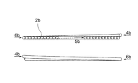
図5に示すように、A層渦巻きコイル3aは、最も内側5aが1つ上の層の渦巻きコイルの最も内側5bと繋がり且つ最も外側4aが1つ下の層の渦巻きコイルの最も外側4bに繋がっている。また、B層渦巻きコイル3bは、最も外側4bが1つ上の層の渦巻きコイルの最も外側4aと繋がり且つ最も内側5bが1つ下の層の渦巻きコイルの最も内側5aに繋がっている。
As shown in FIG. 5, the
図5A(a)に示すように、A層渦巻きコイル3aの銅管2aを上から見ると、最も内側5aから最も外側4aまで渦巻き状になっている。また、図5A(a)の右図に示すように、A層渦巻きコイル3aでは、銅管2aの曲率半径が連続して変化しており、且つ、隣り合う銅管2a同士の隙間が銅管径より小さくなっている。
As shown in FIG. 5A (a), when the
また、図4(a)及び図5Bに示すように、A層渦巻きコイル3aの銅管2aを横から見ると、銅管は、位置7aから最も外側4aまでの部分は、上下方向に同じ位置で渦巻き状に巻かれている。また、最も内側5aは1つ上の層のB層渦巻きコイル3bに繋がっているので、最も内側5aは、1つ上の層のB層渦巻きコイル3bと上下方向に同じ位置であり、そこから銅管の位置が徐々に下がっていき、位置7aで、位置7aから最も外側4aまでの部分と上下方向に同じ位置になる。よって、A層渦巻きコイル3aの最も内側とは、1つ上の層のB層渦巻きコイル3bの銅管の上下方向の位置が下がり始める位置であり、また、A層渦巻きコイル3aの最も外側とは、銅管が1つ下の層のB層渦巻きコイル3bに向かって上下方向の位置が下がり始める直前の位置である。そして、最も内側5aから最も外側4aまでが、A層渦巻きコイル3aである。
Also, as shown in FIGS. 4A and 5B, when the
図5A(b)に示すように、B層渦巻きコイル3bの銅管2bを上から見ると、最も内側5bから最も外側4bまで渦巻き状になっている。また、図5A(b)の右図に示すように、B層渦巻きコイル3bでは、銅管2bの曲率半径が連続して変化しており、且つ、隣り合う銅管2b同士の隙間が銅管径より小さくなっている。
As shown in FIG. 5A (b), when the
また、図3(a)及び図5Cに示すように、B層渦巻きコイル3bの銅管2bを横から見ると、銅管は、最も内側5bから位置6bまでの部分は、上下方向に同じ位置で渦巻き状に巻かれている。また、最も外側4bは1つ上の層のA層渦巻きコイル3aに繋がっているので、最も外側4bは、1つ上の層のA層渦巻きコイル3aと上下方向に同じ位置であり、そこから銅管の位置が徐々に下がっていき、位置6bで、最も内側5bから位置6bまでの部分と上下方向に同じ位置になる。よって、B層渦巻きコイル3bの最も外側とは、1つ上の層のA層渦巻きコイル3aの銅管の上下方向の位置が下がり始める位置であり、また、B層渦巻きコイル3bの最も内側とは、銅管が1つ下の層のA層渦巻きコイル3aに向かって上下方向の位置が下がり始める直前の位置である。そして、最も外側4bから最も内側5bまでが、B層渦巻きコイル3bである。
Further, as shown in FIGS. 3A and 5C, when the
渦巻きコイル積層体1において、A層渦巻きコイル3aの隣り合う銅管2a同士の間隔とB層渦巻きコイル3bの隣り合う銅管2b同士の間隔は、必ずしも等しくなくてもよく、A層渦巻きコイル3aの隣り合う銅管2a同士の間隔とB層渦巻きコイル3bの隣り合う銅管2b同士の間隔は、等しくても等しくなくてもよい。
In the
図5Aに示すように、A層渦巻きコイル3aとB層渦巻きコイル3bとは、両者が繋がっている最も内側の位置5a、5bを始点として見たときに、逆回りの渦巻きになっている。そのため、理論的には、A層渦巻きコイル3aの銅管2aの稜線とB層渦巻きコイル3bの銅管2bの稜線は、線状には重ならず、交差する。図6は、A層渦巻きコイル3aとB層渦巻きコイル3bとの重なりを示す図であり、A層渦巻きコイル3aの銅管2aの稜線を実線で、B層渦巻きコイル3bの銅管2bの稜線を点線で示している。このようなことから、実際の渦巻きコイル積層体中では、A層渦巻きコイル3aの銅管2aとB層渦巻きコイル3bの銅管2bの重なる部分が非常に少なくなる。
As shown in FIG. 5A, the
渦巻きコイル積層体1から銅管2を繰り出して、コイルを巻き解く様子を、図7及び図8を参照して説明する。図7は、図1に示す渦巻きコイル積層体から銅管を繰り出している様子を示す模式的な斜視図である。図8は、図1に示す渦巻きコイル積層体から銅管を繰り出している様子を示す模式的な断面図であり、渦巻きコイル積層体の断面の片側半分を示す図である。図7に示すように、渦巻きコイル積層体1は、敷板16の上に、コイル積層体の中心軸の延長方向が垂直方向になるように置かれて、渦巻きコイルの上の層から順に巻き解かれる。そして、図8に示すように、A層渦巻きコイル3aは、矢印で示すように、内側から外側に向かって順に巻き解かれていき、A層渦巻きコイル3aの最も外側の銅管2aまで繰り出されると、次に、そのA層渦巻きコイル3aの下の層であるB層渦巻きコイル3bが、矢印で示すように、外側から内側に向かって順に巻き解かれていき、B層渦巻きコイル3bの最も内側の銅管2bまで繰り出されると、以降は、同様に、A層渦巻きコイルが、内側から外側に向かって順に巻き解かれ、次いで、B層渦巻きコイルが、外側から内側に向かって順に巻き解かれるということが繰り返される。この時、図6に示すように、繰り出されるのは、常に、最も上にある銅管2であり、レベルワウンドコイルのように、最も下にある銅管が繰り出されるようなことはない。
The manner in which the
本発明の渦巻きコイル積層体は、全てが1本の連続した銅管で作製されている。本発明の渦巻きコイル積層体を形成する銅管は、Cu含有量が95質量%以上且つ0.2%耐力値σ0.2が70MPa以上の銅管であり、継目無銅管である。銅管を構成する銅のCu含有量は、95質量%以上、好ましくは99質量%以上である。また、銅管を構成する銅の0.2%耐力値σ0.2は、70MPa以上である。また、銅管を構成する銅の0.2%耐力値σ0.2が高い程、本発明の効果が表れ易くなり、銅管を構成する銅の0.2%耐力値σ0.2は、特に制限されないが、通常、銅管を構成する銅の0.2%耐力値σ0.2の上限値は320MPa程度である。銅管を構成する銅は、銅の含有量が上記範囲未満とならない範囲で、Sn、Zr、P、Fe、Cr、Ni、Co、Ti、Mn等の種々の合金成分を含有することができる。また、銅管を構成する銅では、上記以外に、O、H、S等の不可避不純物の含有は、許容される。 All the spiral coil laminates of the present invention are made of one continuous copper tube. The copper tube forming the spiral coil laminate of the present invention is a copper tube having a Cu content of 95% by mass or more and a 0.2% proof stress value σ0.2 of 70 MPa or more, and is a seamless copper tube. The Cu content of the copper constituting the copper tube is 95% by mass or more, preferably 99% by mass or more. Moreover, 0.2% yield strength value (sigma) 0.2 of the copper which comprises a copper pipe is 70 Mpa or more. In addition, the higher the 0.2% proof stress value σ0.2 of the copper constituting the copper tube, the more easily the effect of the present invention appears. The 0.2% proof stress value σ0.2 of the copper constituting the copper tube is particularly Although not limited, the upper limit value of 0.2% proof stress value σ0.2 of copper constituting the copper tube is usually about 320 MPa. The copper constituting the copper tube can contain various alloy components such as Sn, Zr, P, Fe, Cr, Ni, Co, Ti, and Mn as long as the copper content is not less than the above range. . Moreover, in copper which comprises a copper pipe, inclusion of inevitable impurities, such as O, H, and S, is accept | permitted besides the above.
銅管を構成する銅としては、例えば、
・りん脱酸銅(JIS H3300 C1220)の半硬質材(σ0.2:230MPa以上)
・JIS H3300 C1565の軟質材(σ0.2:70〜105MPa)
・JIS H3300 C1565の1/2硬質材(σ0.2:120〜265MPa)
・JIS H3300 C1565の3/4硬質材(σ0.2:130〜310MPa)
・JIS H3300 C1862の軟質材(σ0.2:105〜160MPa)
・JIS H3300 C1862の1/2硬質材(σ0.2:135〜300MPa)
・JIS H3300 C1862の3/4硬質材(σ0.2:145〜335MPa)
・JIS H3300 C5010の軟質材(σ0.2:70〜90MPa)
・JIS H3300 C5010の1/2硬質材(σ0.2:120〜270MPa)
・JIS H3300 C1565の3/4硬質材(σ0.2:130〜310MPa)
・JIS H3300 C5015の軟質材(σ0.2:100〜140MPa)
・JIS H3300 C5015の1/2硬質材(σ0.2:110〜290MPa)
・JIS H3300 C5015の3/4硬質材(σ0.2:140〜300MPa)
等のCu含有量が99質量%以上の銅が挙げられる。
また、銅管を構成する銅としては、例えば、
・Cu−0.05〜1.0質量%P系銅合金(σ0.2:70〜160MPa)
・Cu−0.01〜0.06%Fe−0.004〜0.040%P系銅合金(σ0.2:70〜95MPa)
・Cu−0.04〜0.06%Ni−0.004〜0.040%P系銅合金(σ0.2:70〜90MPa)
・Cu−0.02〜0.5%Cr−0.015〜0.05%P系銅合金(σ0.2:70〜160MPa)
等のCu含有量が99質量%以上の銅が挙げられる。
また、銅管を構成する銅としては、例えば、
・Cu−0.80〜1.20%Fe−0.20〜0.40%P系銅合金(σ0.2:80〜140MPa)
・Cu−0.4〜3.5%Ni−0.1〜0.5%P系銅合金(σ0.2:90〜160MPa)
・Cu−0.80〜1.20%Ti−0.015〜0.10%P系銅合金(σ0.2:80〜150MPa)
・Cu−0.35〜1.20%Co−0.20〜0.50%P系銅合金(σ0.2:80〜150MPa)
・Cu−0.40〜1.20%Mn−0.20〜0.40%P系銅合金(σ0.2:80〜150MPa)
・Cu−0.58〜0.72%Sn−0.005〜0.35%Zr−0.004〜0.040P系銅合金(σ0.2:70〜130MPa)
等のCu含有量が95質量%以上の銅が挙げられる。
As copper constituting the copper tube, for example,
・ Phosphorus deoxidized copper (JIS H3300 C1220) semi-hard material (σ0.2: 230 MPa or more)
・ Soft material of JIS H3300 C1565 (σ0.2: 70 to 105 MPa)
・ 1/2 hard material of JIS H3300 C1565 (σ0.2: 120 to 265 MPa)
-3/4 hard material of JIS H3300 C1565 (σ0.2: 130-310 MPa)
・ Soft material of JIS H3300 C1862 (σ0.2: 105 to 160 MPa)
・ 1/2 hard material of JIS H3300 C1862 (σ0.2: 135-300 MPa)
・ 3/4 hard material of JIS H3300 C1862 (σ0.2: 145-335 MPa)
・ Soft material of JIS H3300 C5010 (σ0.2: 70 to 90 MPa)
・ 1/2 hard material of JIS H3300 C5010 (σ0.2: 120 to 270 MPa)
-3/4 hard material of JIS H3300 C1565 (σ0.2: 130-310 MPa)
-Soft material of JIS H3300 C5015 (σ0.2: 100 to 140 MPa)
・ 1/2 hard material of JIS H3300 C5015 (σ0.2: 110-290 MPa)
・ 3/4 hard material of JIS H3300 C5015 (σ0.2: 140 to 300 MPa)
Examples thereof include copper having a Cu content of 99% by mass or more.
Moreover, as copper which comprises a copper pipe, for example,
Cu-0.05 to 1.0 mass% P-based copper alloy (σ0.2: 70 to 160 MPa)
Cu-0.01 to 0.06% Fe-0.004 to 0.040% P-based copper alloy (σ0.2: 70 to 95 MPa)
Cu-0.04-0.06% Ni-0.004-0.040% P-based copper alloy (σ0.2: 70-90 MPa)
Cu-0.02-0.5% Cr-0.015-0.05% P-based copper alloy (σ0.2: 70-160 MPa)
Examples thereof include copper having a Cu content of 99% by mass or more.
Moreover, as copper which comprises a copper pipe, for example,
Cu-0.80-1.20% Fe-0.20-0.40% P-based copper alloy (σ0.2: 80-140 MPa)
Cu-0.4-3.5% Ni-0.1-0.5% P-based copper alloy (σ0.2: 90-160 MPa)
Cu-0.80 to 1.20% Ti-0.015 to 0.10% P-based copper alloy (σ0.2: 80 to 150 MPa)
Cu-0.35 to 1.20% Co-0.20 to 0.50% P-based copper alloy (σ0.2: 80 to 150 MPa)
Cu-0.40 to 1.20% Mn-0.20 to 0.40% P-based copper alloy (σ0.2: 80 to 150 MPa)
Cu-0.58 to 0.72% Sn-0.005 to 0.35% Zr-0.004 to 0.040P-based copper alloy (σ0.2: 70 to 130 MPa)
Examples thereof include copper having a Cu content of 95% by mass or more.
そして、本発明の渦巻きコイル積層体は、銅管が渦巻き状に巻かれている渦巻きコイルが、コイル積層体の中心軸の延長方向に、多数積層されているコイル積層体であり、2種類の渦巻きコイル、すなわち、A層渦巻きコイルとB層渦巻きコイルとからなり、コイル積層体の中心軸の延長方向に、A層渦巻きコイルとB層渦巻きコイルとが交互に繰り返し積層されている。よって、本発明の渦巻きコイル積層体では、銅管は、一番上の層の渦巻きコイルにある銅管の一方の銅管端から一番下の層の渦巻きコイルにある銅管の他方の銅管端まで、連続している。なお、渦巻き状とは、各層の渦巻きコイルを上から見た場合の、銅管の形状を指す。 The spiral coil laminate of the present invention is a coil laminate in which a spiral coil in which a copper tube is wound in a spiral shape is laminated in the extension direction of the central axis of the coil laminate. It consists of a spiral coil, that is, an A layer spiral coil and a B layer spiral coil, and the A layer spiral coil and the B layer spiral coil are alternately and repeatedly stacked in the extending direction of the central axis of the coil laminate. Therefore, in the spiral coil laminate of the present invention, the copper tube is connected to the other copper of the copper tube in the spiral coil in the lowermost layer from the end of the copper tube in the spiral coil in the uppermost layer. Continuous to the end of the tube. The spiral shape means the shape of the copper tube when the spiral coil of each layer is viewed from above.
A層渦巻きコイルは、最も内側が1つ上の層の渦巻きコイルの最も内側と繋がり且つ最も外側が1つ下の層の渦巻きコイルの最も外側に繋がっている。また、B層渦巻きコイルは、最も外側が1つ上の層の渦巻きコイルの最も外側と繋がり且つ最も内側が1つ下の層の渦巻きコイルの最も内側に繋がっている。 In the A-layer spiral coil, the innermost side is connected to the innermost side of the uppermost spiral coil and the outermost side is connected to the outermost side of the lowermost spiral coil. In addition, the outermost layer of the B layer spiral coil is connected to the outermost side of the spiral coil of the uppermost layer, and the innermost side is connected to the innermost side of the spiral coil of the lowermost layer.
そして、A層渦巻きコイルとその下にあるB層渦巻きコイルとが繋がっている最も外側の位置を始点として見たときに、両者は逆回りの渦巻きになっており、且つ、B層渦巻きコイルとその下にあるA層渦巻きコイルとが繋がっている最も内側の位置を始点として見たときに、両者は逆回りの渦巻きになっている。なお、図5Aに示す形態例では、最も内側の位置を始点としたときに、A層渦巻きコイルは左巻きの渦巻きに巻かれ、且つ、B層渦巻きコイルは右巻きの渦巻きに巻かれているが、これに制限されず、本発明の渦巻きコイル積層体では、最も内側の位置を始点としたときに、A層渦巻きコイルは左巻きの渦巻きに巻かれ、且つ、B層渦巻きコイルは右巻きの渦巻きに巻かれていてもよいし、あるいは、最も内側の位置を始点としたときに、A層渦巻きコイルは右巻きの渦巻きに巻かれ、且つ、B層渦巻きコイルは左巻きの渦巻きに巻かれていてもよい。なお、A層渦巻きコイルとB層渦巻きコイルの最も外側の位置を始点としたときも、A層渦巻きコイルとB層渦巻きコイルは、逆回りの渦巻きになる。 When the outermost position where the A layer spiral coil and the B layer spiral coil below it are connected is seen as the starting point, both are spirals in the reverse direction, and the B layer spiral coil When the innermost position where the lower layer A spiral coil is connected is viewed as the starting point, the two spirals are reversed. In the embodiment shown in FIG. 5A, the A layer spiral coil is wound in a left-handed spiral and the B layer spiral coil is wound in a right-handed spiral, starting from the innermost position. In the spiral coil laminate of the present invention, the A layer spiral coil is wound in the left-handed spiral and the B layer spiral coil is the right-handed spiral in the innermost position. Or the A-layer spiral coil is wound in a right-handed spiral and the B-layer spiral coil is wound in a left-handed spiral, starting from the innermost position. Also good. Even when the outermost position of the A layer spiral coil and the B layer spiral coil is used as the starting point, the A layer spiral coil and the B layer spiral coil are reversed.
A層渦巻きコイルは、上下方向の位置が徐々に下がりながら巻かれている部分と、上下方向が同じ位置で渦巻き状に巻かれている部分と、からなる。図5Aに示す形態例では、最も内側5aから位置7aまでの部分が、上下方向の位置が徐々に下がりながら巻かれている部分に相当し、また、位置7aから最も外側4aまでの部分が、上下方向が同じ位置で渦巻き状に巻かれている部分に相当する。本発明の渦巻きコイル積層体では、上下方向が同じ位置で渦巻き状に巻かれている部分が、各層を形成するので、A層渦巻きコイルのうちの、上下方向が同じ位置で渦巻き状に巻かれている部分の上下方向の位置を、A層の位置とする。B層渦巻きコイルでも同様に、B層渦巻きコイルのうちの、上下方向が同じ位置で渦巻き状に巻かれている部分の上下方向の位置を、B層の位置とする。そのため、A層渦巻きコイルの銅管を横から見ると、A層渦巻きコイルの銅管の最も内側の上下方向の位置は、1つ上のB層の位置と同じ位置であり、そこから銅管の位置は徐々に下がっていき、A層の位置まで、銅管の外径1つ分下がる。そして、A層の位置まで下がったところから最も外側までは、銅管の上下方向の位置は同じである。つまり、A層渦巻きコイルの最も内側とは、銅管の上下方向の位置が1つ上の層のB層渦巻きコイルのB層の位置からA層の位置に向かって下がり始める位置であり、また、A層渦巻きコイルの最も外側とは、銅管の上下方向の位置が1つ下の層のB層渦巻きコイルのB層の位置に向かって下がり始める直前の位置である。図4に示す形態例では、最も内側の位置から渦巻きの中心を中心とする中心角で約180°分かけて、銅管の上下方向の位置が、B層の位置からA層の位置まで下がっているが、これに制限されず、本発明の効果を損なわない範囲で適宜選択される。そして、本発明の渦巻きコイル積層体では、最も内側の位置から渦巻きの中心を中心とする中心角で90〜270°分かけて、銅管の上下方向の位置が、B層の位置からA層の位置まで下がっていることが好ましい。
The A-layer spiral coil is composed of a portion that is wound while the position in the vertical direction is gradually lowered, and a portion that is wound in a spiral shape at the same position in the vertical direction. In the example shown in FIG. 5A, the portion from the
また、B層渦巻きコイルは、上下方向の位置が徐々に下がりながら巻かれている部分と、上下方向が同じ位置で渦巻き状に巻かれている部分と、からなる。図5Aに示す形態例では、最も外側4bから位置6bまでの部分が、上下方向の位置が徐々に下がりながら巻かれている部分に相当し、また、位置6bから最も内側5bまでの部分が、上下方向が同じ位置で渦巻き状に巻かれている部分に相当する。そのため、B層渦巻きコイルの銅管を横から見ると、B層渦巻きコイルの銅管の最も外側の上下方向の位置は、1つ上のA層の位置と同じ位置であり、そこから銅管の位置は徐々に下がっていき、B層の位置まで、略銅管の外径1つ分下がる。そして、B層の位置まで下がったところから最も内側までは、銅管の上下方向の位置は同じである。つまり、B層渦巻きコイルの最も外側とは、銅管の上下方向の位置が1つ上の層のA層渦巻きコイルのA層の位置からB層の位置に向かって下がり始める位置であり、また、B層渦巻きコイルの最も内側とは、銅管の上下方向の位置が1つ下の層のA層渦巻きコイルのA層の位置に向かって下がり始める直前の位置である。図3に示す形態例では、最も外側の位置から渦巻きの中心を中心とする中心角で約180°分かけて、銅管の上下方向の位置が、A層の位置からB層の位置まで下がっているが、これに制限されず、本発明の効果を損なわない範囲で適宜選択される。そして、本発明の渦巻きコイル積層体では、最も外側の位置から渦巻きの中心を中心とする中心角で90〜270°分かけて、銅管の上下方向の位置が、A層の位置からB層の位置まで下がっていることが好ましい。
Further, the B layer spiral coil is composed of a portion that is wound while the position in the vertical direction is gradually lowered, and a portion that is wound in a spiral shape at the same position in the vertical direction. In the example shown in FIG. 5A, the portion from the outermost 4b to the
A層渦巻きコイルでは、銅管の曲率半径は連続して変化しており、且つ、隣り合う銅管同士の隙間が銅管の直径より小さくなるように巻かれている。B層渦巻きコイルでも、同様に、銅管の曲率半径は連続して変化しており、且つ、隣り合う銅管同士の隙間が銅管の直径より小さくなるように巻かれている。 In the A layer spiral coil, the radius of curvature of the copper pipe is continuously changed, and the gap between adjacent copper pipes is wound so as to be smaller than the diameter of the copper pipe. Similarly, in the B layer spiral coil, the radius of curvature of the copper tube is continuously changed, and the gap between adjacent copper tubes is wound so as to be smaller than the diameter of the copper tube.
なお、本発明の渦巻きコイル積層体の銅管の渦巻き形状とは、理論的には、銅管の曲率半径が連続して変化し、且つ、隣り合う銅管同士の隙間が銅管径より小さい形状を指すが、本発明の効果を損なわないものであれば、それに近似する形状のものも、本発明の渦巻きコイル積層体に含まれる。つまり、本発明の効果を損なわない範囲であれば、銅管の曲率半径が連続して変化していない箇所があったり、あるいは、隣り合う銅管同士の隙間が銅管径より大きくなっている箇所があってもよい。 The spiral shape of the copper tube of the spiral coil laminate of the present invention theoretically means that the radius of curvature of the copper tube continuously changes and the gap between adjacent copper tubes is smaller than the copper tube diameter. The shape refers to a shape, but if it does not impair the effect of the present invention, a shape approximate to that is also included in the spiral coil laminate of the present invention. That is, as long as the effect of the present invention is not impaired, there are places where the radius of curvature of the copper pipe does not continuously change, or the gap between adjacent copper pipes is larger than the copper pipe diameter. There may be places.
本発明の渦巻きコイル積層体を形成する銅管は、ルームエアコン、パッケージエアコンなどの空調機用熱交換器、冷凍機等の伝熱銅管又は冷媒配銅管として用いられる伝熱銅管であり、平滑銅管又は内面溝付銅管である。 The copper tube forming the spiral coil laminate of the present invention is a heat transfer copper tube used as a heat exchanger for air conditioners such as room air conditioners and packaged air conditioners, a heat transfer copper tube such as a refrigerator, or a refrigerant copper distribution tube. A smooth copper tube or an internally grooved copper tube.
銅管の外径は、特に制限されないが、好ましくは3〜13mm、特に好ましくは3〜10mmである。特に、本発明の渦巻きコイル積層体は、渦巻きコイル積層体を形成する銅管の外径が3〜7mmと小さくても、銅管の繰り出しトラブルが起こり難くい。 The outer diameter of the copper tube is not particularly limited, but is preferably 3 to 13 mm, particularly preferably 3 to 10 mm. In particular, in the spiral coil laminate of the present invention, even if the outer diameter of the copper tube forming the spiral coil laminate is as small as 3 to 7 mm, troubles in feeding out the copper tube hardly occur.
A層渦巻きコイル又はB層渦巻きコイル1つ当たりの銅管の巻き数は、特に制限されないが、好ましくは10〜200、特に好ましくは30〜60である。 The number of turns of the copper tube per A-layer spiral coil or B-layer spiral coil is not particularly limited, but is preferably 10-200, particularly preferably 30-60.
図1に示す形態例では、渦巻きコイル積層体は、一番上がA層渦巻きコイルの層であり、順に下に、B層、A層、B層、A層、B層・・・と交互に繰り返されて、一番下がA層渦巻きコイルの層となっているが、これに限定されるものではなく、A層渦巻きコイルとB層渦巻きコイルが交互に繰り返されて積層されているのであれば、一番上がA層渦巻きコイルであってもB層渦巻きコイルであってもよく、また、一番下がA層渦巻きコイルであってもB層渦巻きコイルであってもよい。 In the embodiment shown in FIG. 1, the spiral coil laminate is the layer of the A-layer spiral coil at the top, and in turn, B layer, A layer, B layer, A layer, B layer,. The bottom layer is the layer of the A layer spiral coil, but the layer is not limited to this, and the A layer spiral coil and the B layer spiral coil are alternately stacked. If so, the uppermost layer may be an A-layer spiral coil or a B-layer spiral coil, and the lowermost layer may be an A-layer spiral coil or a B-layer spiral coil.
本発明の渦巻きコイル積層体では、一番上の渦巻きコイルの層の上には渦巻きコイルの層がないことから、一番上の渦巻きコイルの層の銅管は、1つ上の層の渦巻きコイルの層とは繋がっていない。そのため、本発明の渦巻きコイル積層体では、一番上の層の渦巻きコイルには、上下方向の位置から徐々に低くなっていく部分がなくてもよい。 In the spiral coil laminate of the present invention, since there is no spiral coil layer above the top spiral coil layer, the copper coil of the top spiral coil layer is the spiral of the upper layer. It is not connected to the coil layer. Therefore, in the spiral coil laminate of the present invention, the spiral coil in the uppermost layer may not have a portion that gradually decreases from the vertical position.
本発明の渦巻きコイル積層体では、A層渦巻きコイル及びB層渦巻きコイルの合計層数は、特に限定されないが、好ましくは10〜250、特に好ましくは20〜80である。 In the spiral coil laminate of the present invention, the total number of layers of the A layer spiral coil and the B layer spiral coil is not particularly limited, but is preferably 10 to 250, particularly preferably 20 to 80.
本発明の渦巻きコイル積層体に係るA層渦巻きコイルにおいて、隣り合う銅管同士の間には隙間が形成されている。また、本発明の渦巻きコイル積層体に係るB層渦巻きコイルにおいて、隣り合う銅管同士の間には隙間が形成されている。そして、本発明の渦巻きコイル積層体では、銅管の外径に対する銅管間の隙間の比が、好ましくは0.01以上1.0未満、特に好ましくは0.05〜0.2である。銅管の外径に対する銅管間の隙間の比が上記範囲にあることにより、銅管の間に、1つ上又は1つ下の層の銅管が入り込み難くなる。なお、銅管の外径に対する銅管間の隙間の比(p)は、以下の式(1)によって算出される。
p=(W−d×n)/(n−1) (1)
式(1)中、Wは渦巻きコイルの断面における片側半分の幅であり、図4中の符号Wで示す長さであり、また、dは銅管の外径であり、また、nは渦巻きコイルの断面における片側半分に存在する銅管の数である。
In the A-layer spiral coil according to the spiral coil laminate of the present invention, a gap is formed between adjacent copper tubes. In the B layer spiral coil according to the spiral coil laminate of the present invention, a gap is formed between adjacent copper tubes. And in the spiral coil laminated body of this invention, ratio of the clearance gap between copper tubes with respect to the outer diameter of a copper tube becomes like this. Preferably it is 0.01 or more and less than 1.0, Most preferably, it is 0.05-0.2. When the ratio of the gap between the copper pipes with respect to the outer diameter of the copper pipe is in the above range, the copper pipe of the upper layer or the lower layer is difficult to enter between the copper pipes. In addition, ratio (p) of the clearance gap between copper pipes with respect to the outer diameter of a copper pipe is computed by the following formula | equation (1).
p = (W−d × n) / (n−1) (1)
In the formula (1), W is the width of one half of the cross section of the spiral coil, is the length indicated by the symbol W in FIG. 4, d is the outer diameter of the copper tube, and n is the spiral It is the number of copper tubes existing on one half of the cross section of the coil.
なお、本発明おいて、隣り合う銅管同士の間隔とは、図9に示すように、銅管の銅管軸方向に垂直な面で切った断面において、隣り合う銅管の中心間の距離(符号8)を指す。この隣り合う銅管同士の間隔は、銅管の稜線間の距離に等しい。また、本発明において、銅管間の隙間とは、図9に示すように、銅管の銅管軸方向に垂直な面で切った断面において、隣り合う銅管間にできる隙間(符号9)を指す。なお、図9は、図4中の点線で囲った部分(符号A)の拡大図である。 In addition, in this invention, as shown in FIG. 9, the space | interval of adjacent copper tubes is the distance between the centers of adjacent copper tubes in the cross section cut by the surface perpendicular | vertical to the copper tube axial direction of a copper tube. (Reference numeral 8). The interval between the adjacent copper tubes is equal to the distance between the ridge lines of the copper tubes. Further, in the present invention, the gap between the copper pipes, as shown in FIG. 9, is a gap formed between adjacent copper pipes (symbol 9) in a cross section cut by a plane perpendicular to the copper pipe axial direction of the copper pipe. Point to. FIG. 9 is an enlarged view of a portion (symbol A) surrounded by a dotted line in FIG.
渦巻きコイルの外径(図4中、符号D1で示す長さ)及び渦巻きコイルの内径(図4中、符号D2で示す長さ)は、銅管の外径及び巻き数に応じて適宜選択されるが、渦巻きコイルの外径は、好ましくは800〜1500mm、特に好ましくは1000〜1100mmであり、また、渦巻きコイルの内径は、好ましくは300〜1000mm、特に好ましくは500〜700mmである。 (In FIG. 4, the length indicated by reference numeral D1) the outer diameter of the spiral coil (in FIG. 4, the length indicated by a symbol D 2) the inner diameter of and a spiral coil, appropriately selected depending on the outer diameter and number of turns of copper pipe However, the outer diameter of the spiral coil is preferably 800 to 1500 mm, particularly preferably 1000 to 1100 mm, and the inner diameter of the spiral coil is preferably 300 to 1000 mm, particularly preferably 500 to 700 mm.
本発明の渦巻きコイル積層体では、A層渦巻きコイルとB層渦巻きコイルとは、両者が繋がっている位置を始点として見たときに、逆回りの渦巻きになっているので、理論的には、A層渦巻きコイルの銅管の稜線とB層渦巻きコイルの銅管の稜線が、線状には重ならずに交差する。このようなことから、実際の渦巻きコイル積層体中では、A層渦巻きコイルの銅管の稜線とB層渦巻きコイルの銅管の稜線の重なる部分が非常に少なくなる。そのため、最終熱処理時に、銅管同士の溶着による貼り付きが起こっても、従来の段落ちレベルワウンドコイルのように、銅管が線状に貼り付くということが起こり難いので、本発明の渦巻きコイル積層体は、高強度銅からなる銅管のコイル積層体でありながら、銅管の線状の貼り付きを原因とする銅管の繰り出しトラブルが起こり難い。 In the spiral coil laminate of the present invention, the A-layer spiral coil and the B-layer spiral coil are in a reverse spiral when viewed from the position where both are connected, theoretically, The ridge line of the copper tube of the A layer spiral coil intersects the ridge line of the copper tube of the B layer spiral coil without overlapping in a linear shape. For this reason, in the actual spiral coil laminate, there are very few overlapping portions of the ridge line of the copper tube of the A layer spiral coil and the ridge line of the copper tube of the B layer spiral coil. Therefore, even if sticking due to welding of copper tubes occurs during the final heat treatment, unlike the conventional step-down level wound coil, it is unlikely that the copper tube sticks linearly, so the spiral coil of the present invention Although the laminate is a coil laminate of a copper tube made of high-strength copper, it is difficult to cause a trouble of feeding out the copper tube due to the linear sticking of the copper tube.
また、本発明の渦巻きコイル積層体では、上の層の渦巻きコイルから順に巻き解かれるので、本発明の渦巻きコイル積層体中の銅管は、上から他の銅管の荷重がかかっているような状態で繰り出されることはない。そのため、本発明の渦巻きコイル積層体では、銅管が繰り出されるときに、段落ちレベルワンドコイルのような、敷板の抵抗を原因とする銅管の繰り出しトラブルが起こらない。また、本発明の渦巻きコイル積層体では、例え、巻き解き時に、自重による整直が生じ難いため、下方の巻き解かれた銅管が巻き曲率を保ったまま、バネ状の螺旋管となって上方に繰り出されたとしても、繰り出し時の引っ掛かりが起こらないので、繰り出しトラブルが生じ易い。 Further, in the spiral coil laminate of the present invention, the copper coil in the spiral coil laminate of the present invention seems to be loaded from the other copper tube from the top because it is unwound in order from the spiral coil of the upper layer. It will not be paid out in a bad state. Therefore, in the spiral coil laminated body of the present invention, when the copper pipe is drawn out, there is no trouble of drawing out the copper pipe due to the resistance of the floor plate, such as a step-down level wand coil. Further, in the spiral coil laminate of the present invention, for example, when unwinding, it is difficult for straightening due to its own weight, so that the unrolled copper tube below becomes a spring-like spiral tube while maintaining the winding curvature. Even if it is fed upward, there is no catch at the time of feeding, so that a feeding trouble is likely to occur.
本発明の渦巻きコイル積層体の積み重ね体は、本発明の渦巻きコイル積層体が、コイル積層体の中心軸の延長方向に、2以上積み重ねられており、
上下の渦巻きコイル積層体の銅管が、接続部材で繋がれていること、
を特徴とする渦巻きコイル積層体の積み重ね体である。
In the stack of the spiral coil laminate of the present invention, the spiral coil laminate of the present invention is stacked two or more in the extending direction of the central axis of the coil laminate,
The copper tubes of the upper and lower spiral coil laminates are connected by a connecting member,
Is a stack of spiral coil laminates.
図11には、渦巻きコイル積層体1a、1bが、コイル積層体の中心軸の延長方向に、2つ積み重ねられている渦巻きコイル積層体の積み重ね体を示す。本発明の渦巻きコイル積層体は、通常、2〜3個が、コイル積層体の中心軸の延長方向に積み重ねられた状態で、銅管の使用場所に置かれ、巻き解かれる。
FIG. 11 shows a stack of spiral coil stacks in which two
このとき、図12(a)に示すように、上にある渦巻きコイル積層体の一番下の層の渦巻きコイルの銅管2aの銅管端と、その下にある渦巻きコイル積層体の一番上の層の渦巻きコイルの銅管2bの銅管端とを近づけ、次いで、図12(b)に示すように、接続部材17で、上の渦巻きコイル積層体の銅管2aと下の渦巻きコイル積層体の銅管2bとが繋がれている。なお、図12は、上下の渦巻きコイル積層体の銅管が、接続部材で繋がれている様子を示す模式図である。
At this time, as shown in FIG. 12 (a), the copper tube end of the
接続部材で繋がれている2以上の渦巻きコイル積層体を巻き解きしていく際、銅銅管のねじれを接続部材で吸収するため、接続部材は一定のねじれ強度を有するチューブなどを用いることができる。例えば、塩化ビニル性のチューブや、樹脂製チューブ、銅管などを用いることができる。 When unwinding two or more spiral coil laminates connected by a connecting member, the connecting member absorbs the torsion of the copper-copper tube by the connecting member, so that the connecting member uses a tube having a certain torsional strength. it can. For example, a vinyl chloride tube, a resin tube, a copper tube, or the like can be used.
そして、本発明の渦巻きコイル積層体が、コイル積層体の中心軸の延長方向に、2以上積み重ねられ、上下の渦巻きコイル積層体の銅管が、接続部材で繋がれていることにより、上の渦巻きコイル積層体の銅管が全て繰り出された後、途切れることなく連続して、下の渦巻きコイル積層体の銅管が繰り出される。 And the spiral coil laminated body of the present invention is stacked two or more in the extension direction of the central axis of the coil laminated body, and the copper tubes of the upper and lower spiral coil laminated bodies are connected by connecting members, After all the copper tubes of the spiral coil laminate are drawn out, the copper tubes of the lower spiral coil laminate are drawn out continuously without interruption.
1 渦巻きコイル積層体
2、2a、2b、22 銅管
3a A層渦巻きコイル
3b B層渦巻きコイル
4a、4b 渦巻きコイルの最も外側
5a、5b 渦巻きコイルの最も内側
8 隣り合う銅管同士の間隔
9 銅管間の隙間
13 コイル積層体の中心軸
16 敷板
17 接続部材
20 レベルワウンドコイル
21 ボビン
23a、23b、27a、27b 整列巻きコイル
24 ボビンの内筒
33 レベルワウンドコイルの中心軸の延長方向
D1 渦巻きコイルの外径
D2 渦巻きコイルの内径
W 渦巻きコイルの片側半分の幅
DESCRIPTION OF
Claims (4)
最も内側が1つ上の層の渦巻きコイルの最も内側と繋がり且つ最も外側が1つ下の層の渦巻きコイルの最も外側に繋がるA層渦巻きコイルと、最も外側が1つ上の層の渦巻きコイルの最も外側と繋がり且つ最も内側が1つ下の層の渦巻きコイルの最も内側に繋がるB層渦巻きコイルと、からなり、
該A層渦巻きコイルと該B層渦巻きコイルとが交互に繰り返されており、
各層の該渦巻きコイルの銅管は、曲率半径が連続して変化し、且つ、隣り合う銅管同士の隙間が銅管径より小さくなるように巻かれており、
該銅管は、Cu含有量が95質量%以上且つ0.2%耐力値σ0.2が70MPa以上の銅管であること、
を特徴とする渦巻きコイル積層体。 A spiral coil in which a copper tube is wound in a spiral shape is a coil laminate in which a large number of layers are laminated in the extending direction of the central axis of the coil laminate,
A-layer spiral coil with the innermost side connected to the innermost side of the uppermost layer spiral coil and the outermost side connected to the outermost side of the lowermost layer spiral coil, and the outermost side spiral coil of the uppermost layer A B-layer spiral coil connected to the outermost side of the innermost layer and connected to the innermost side of the spiral coil of the lowermost layer on the innermost side,
The A layer spiral coil and the B layer spiral coil are alternately repeated,
The copper tube of the spiral coil of each layer is wound so that the radius of curvature continuously changes and the gap between adjacent copper tubes is smaller than the copper tube diameter,
The copper pipe is a copper pipe having a Cu content of 95% by mass or more and a 0.2% proof stress value σ0.2 of 70 MPa or more,
A spiral coil laminate characterized by the following.
上下の渦巻きコイル積層体の銅管が、接続部材で繋がれていること、
を特徴とする渦巻きコイル積層体の積み重ね体。 Two or more spiral coil laminates according to any one of claims 1 to 3 are stacked in the extending direction of the central axis of the coil laminate,
The copper tubes of the upper and lower spiral coil laminates are connected by a connecting member,
A stack of spiral coil laminates characterized by
Priority Applications (1)
| Application Number | Priority Date | Filing Date | Title |
|---|---|---|---|
| JP2016083731A JP2017193396A (en) | 2016-04-19 | 2016-04-19 | Spiral coil laminate and stacked body of spiral coil laminate |
Applications Claiming Priority (1)
| Application Number | Priority Date | Filing Date | Title |
|---|---|---|---|
| JP2016083731A JP2017193396A (en) | 2016-04-19 | 2016-04-19 | Spiral coil laminate and stacked body of spiral coil laminate |
Publications (1)
| Publication Number | Publication Date |
|---|---|
| JP2017193396A true JP2017193396A (en) | 2017-10-26 |
Family
ID=60156272
Family Applications (1)
| Application Number | Title | Priority Date | Filing Date |
|---|---|---|---|
| JP2016083731A Pending JP2017193396A (en) | 2016-04-19 | 2016-04-19 | Spiral coil laminate and stacked body of spiral coil laminate |
Country Status (1)
| Country | Link |
|---|---|
| JP (1) | JP2017193396A (en) |
Cited By (1)
| Publication number | Priority date | Publication date | Assignee | Title |
|---|---|---|---|---|
| WO2023276258A1 (en) * | 2021-06-30 | 2023-01-05 | 株式会社フジクラ | Accommodation unit and wound body |
-
2016
- 2016-04-19 JP JP2016083731A patent/JP2017193396A/en active Pending
Cited By (1)
| Publication number | Priority date | Publication date | Assignee | Title |
|---|---|---|---|---|
| WO2023276258A1 (en) * | 2021-06-30 | 2023-01-05 | 株式会社フジクラ | Accommodation unit and wound body |
Similar Documents
| Publication | Publication Date | Title |
|---|---|---|
| EP2846961B1 (en) | Tube for a heat exchanger | |
| US10995884B1 (en) | Multilayer composite pipe and pipe assemblies including reflective insulation | |
| JPH11510117A (en) | Cladding shape memory alloy composite structure and method | |
| JP5913660B1 (en) | Swirl coil laminate and stack of spiral coil laminate | |
| JP2017193396A (en) | Spiral coil laminate and stacked body of spiral coil laminate | |
| US7631828B2 (en) | Level wound coil, method of manufacturing same, and package for same | |
| US20060201839A1 (en) | Level wound coil mounted on pallet, and package for same | |
| JP2005327834A (en) | Coil and its manufacturing method | |
| JP7089839B2 (en) | Manufacturing method of spiral coil laminated body, manufacturing method of stacked body of spiral coil laminated body | |
| JP2021054555A (en) | Wire winding method and aligned winding coil | |
| JP5276298B2 (en) | Continuous segment core material used for rotor laminated core and rotor laminated core using the same | |
| JP4001179B2 (en) | Level-wound coil, manufacturing method thereof, and package for level-wound coil | |
| CN101410913A (en) | Magnetic flux return path with collated bands of wire | |
| CN109517965B (en) | Horizontal winding coil for metallurgical heat treatment of metal tubes in multilayer construction | |
| JP2007084207A (en) | Pipe feeding method for level wound coil | |
| JP4311962B2 (en) | Level-wound coil, level-wound coil package, pipe supply method from level-wound coil, pipe supply method from level-wound coil package | |
| JP4133733B2 (en) | Method of supplying pipe from level wound coil, method of supplying pipe from package of level wound coil and unwinding device | |
| JP5132845B2 (en) | Seamless tube, coil, level-wound coil, method for manufacturing level-wound coil, cross-fin tube type heat exchanger, and method for manufacturing cross-fin tube type heat exchanger | |
| WO2022123906A1 (en) | Multilayer hose | |
| JP3599110B2 (en) | Method of supplying pipe from level-wound coil and method of supplying pipe from level-wound coil package | |
| CN108087636A (en) | A kind of metal shock reducing multiple tube that can be used for welding and preparation method thereof | |
| JP6648924B2 (en) | Level wound coil, method of manufacturing level wound coil, and method of unwinding level wound coil | |
| JP5260374B2 (en) | Level wound coil package | |
| JP2014053396A (en) | Laminated inductor | |
| JP2004142854A (en) | Level wound coil laminate body, package body of level wound coil, and pipe feeding method from level wound coil |
Legal Events
| Date | Code | Title | Description |
|---|---|---|---|
| A621 | Written request for application examination |
Free format text: JAPANESE INTERMEDIATE CODE: A621 Effective date: 20190411 |
|
| RD02 | Notification of acceptance of power of attorney |
Free format text: JAPANESE INTERMEDIATE CODE: A7422 Effective date: 20190411 |
|
| A977 | Report on retrieval |
Free format text: JAPANESE INTERMEDIATE CODE: A971007 Effective date: 20200210 |
|
| A131 | Notification of reasons for refusal |
Free format text: JAPANESE INTERMEDIATE CODE: A131 Effective date: 20200218 |
|
| A521 | Written amendment |
Free format text: JAPANESE INTERMEDIATE CODE: A523 Effective date: 20200413 |
|
| A02 | Decision of refusal |
Free format text: JAPANESE INTERMEDIATE CODE: A02 Effective date: 20201006 |