JP2017192889A - Ion exchange device - Google Patents

Ion exchange device Download PDF

Info

Publication number
JP2017192889A
JP2017192889A JP2016083623A JP2016083623A JP2017192889A JP 2017192889 A JP2017192889 A JP 2017192889A JP 2016083623 A JP2016083623 A JP 2016083623A JP 2016083623 A JP2016083623 A JP 2016083623A JP 2017192889 A JP2017192889 A JP 2017192889A
Authority
JP
Japan
Prior art keywords
water
valve
unit
raw water
operation tool
Prior art date
Legal status (The legal status is an assumption and is not a legal conclusion. Google has not performed a legal analysis and makes no representation as to the accuracy of the status listed.)
Pending
Application number
JP2016083623A
Other languages
Japanese (ja)
Inventor
佐藤 元
Hajime Sato
元 佐藤
Current Assignee (The listed assignees may be inaccurate. Google has not performed a legal analysis and makes no representation or warranty as to the accuracy of the list.)
Miura Co Ltd
Original Assignee
Miura Co Ltd
Priority date (The priority date is an assumption and is not a legal conclusion. Google has not performed a legal analysis and makes no representation as to the accuracy of the date listed.)
Filing date
Publication date
Application filed by Miura Co Ltd filed Critical Miura Co Ltd
Priority to JP2016083623A priority Critical patent/JP2017192889A/en
Publication of JP2017192889A publication Critical patent/JP2017192889A/en
Pending legal-status Critical Current

Links

Images

Landscapes

  • Treatment Of Water By Ion Exchange (AREA)

Abstract

PROBLEM TO BE SOLVED: To provide an ion exchange device, when a user or an operator changes a bypass changeover valve or a raw water strainer or a treatment water strainer is cleaned, capable of performing required operations using the operation tools arranged at an operation tool arrangement part.SOLUTION: Provided is an ion exchange device comprising: a pressure tank; a regenerated liquid feed unit; a piping unit; a flow passage control valve unit; and an enclosure. The enclosure is provided with an operation tool arrangement part 621 at any of the front, rear, left and right faces, the piping unit being an assembly including: bypass changeover valve operation tools 5151, 5311; a raw water strainer operational tool 5111; and a treatment water strainer operational tool 5221. This assembly is arranged in the vicinity at the face provided with the operation tool arrangement part 621 to the enclosure, and the bypass changeover operation tools 5151, 5311, the raw water strainer operation tool 5111 and the treatment water strainer operation tool 5221 are arranged so as to be assembled at the operation tool arrangement part 621.SELECTED DRAWING: Figure 10

Description

本発明は、硬水軟化装置等のイオン交換装置に関する。   The present invention relates to an ion exchange device such as a water softening device.

近年、一般家庭の生活用水や食品製造業の加工用水として、軟水の特性や効能が注目されるようになり、軟水を製造するためのイオン交換装置(いわゆる、硬水軟化装置)が普及し始めている。軟水製造用のイオン交換装置は、水道水や地下水等の原水に含まれる硬度成分(カルシウムイオン及びマグネシウムイオン)を陽イオン交換樹脂により吸着して除去し、処理水である軟水を製造する(特許文献1参照)。   In recent years, the characteristics and effectiveness of soft water have attracted attention as water for domestic use and processing water in the food manufacturing industry, and ion exchange devices for producing soft water (so-called soft water softening devices) have begun to spread. . The ion-exchange device for soft water production produces soft water, which is treated water, by adsorbing and removing hardness components (calcium ions and magnesium ions) contained in raw water such as tap water and groundwater with a cation exchange resin (patent) Reference 1).

上記のような硬水軟化装置において、イオン交換樹脂床は、所定の採水量に達すると、イオン交換基が硬度成分でほぼ飽和状態になり、イオン交換能力を失う状態(即ち破過状態)になる。そこで、硬水軟化装置では、イオン交換樹脂床が破過状態になる前に、イオン交換樹脂床が収容される圧力タンクへ再生液としての塩水を供給してイオン交換能力を回復させる再生動作が行われる。再生液としての塩水は、再生液タンク(塩水タンク)に貯留される。   In the water softening device as described above, when the ion exchange resin bed reaches a predetermined amount of water, the ion exchange group becomes almost saturated with the hardness component and loses the ion exchange ability (that is, breakthrough state). . Therefore, in the water softening device, before the ion exchange resin bed becomes a breakthrough state, a regeneration operation is performed to restore ion exchange capacity by supplying salt water as a regeneration solution to the pressure tank in which the ion exchange resin bed is accommodated. Is called. Salt water as a regenerating solution is stored in a regenerating solution tank (salt water tank).

一般的な硬水軟化装置は、イオン交換樹脂床が収容される圧力タンクと、再生液としての塩水が貯留される再生液タンクと、原水を導入する原水導入部及び圧力タンク内でイオン交換樹脂により処理された処理水を導出する処理水導出部を有する配管部とを備えて構成される。圧力タンクには、通水工程や再生工程等の流路を切り換えるためのコントロールバルブが設けられ、このコントロールバルブを介して、圧力タンクは、配管部と接続される。更に、家庭用の硬水軟化装置では、これらの要素に加えて、圧力タンク、再生液タンク及び配管部を収容する筐体を備えて構成される。   A general water softening device includes a pressure tank in which an ion-exchange resin bed is accommodated, a regenerated liquid tank in which salt water as a regenerated liquid is stored, a raw water introduction unit for introducing raw water, and an ion exchange resin in the pressure tank. And a piping unit having a treated water deriving unit for deriving treated treated water. The pressure tank is provided with a control valve for switching a flow path such as a water flow process and a regeneration process, and the pressure tank is connected to a piping section through the control valve. Furthermore, the home water softening device is configured to include a housing for accommodating a pressure tank, a regenerated liquid tank, and a piping portion in addition to these elements.

更に、硬水軟化装置には、手動で操作される操作部がいくつか設けられる。例えば、バイパス切替バルブ操作部、原水ストレーナ操作部、処理水ストレーナ操作部、等である。バイパス切替バルブ操作部は、バイパス切替バルブにより水の流通経路を切り替える際に手動で操作される。原水ストレーナ操作部は、原水ストレーナを洗浄する際に手動で操作される。処理水ストレーナ操作部は、処理水ストレーナを洗浄する際に手動で操作される。   Furthermore, the water softening device is provided with several operation units that are manually operated. For example, a bypass switching valve operation unit, a raw water strainer operation unit, a treated water strainer operation unit, and the like. The bypass switching valve operation unit is manually operated when the water flow path is switched by the bypass switching valve. The raw water strainer operation unit is manually operated when cleaning the raw water strainer. The treated water strainer operation unit is manually operated when cleaning the treated water strainer.

特開2015−166070号公報Japanese Patent Laying-Open No. 2015-166070

しかしながら、従来の硬水軟化装置において、手動で操作される様々な操作部は、バラバラの位置に設けられていた。そのため、操作部にアクセスすることが面倒である、という不都合があった。   However, in the conventional water softening device, various operation units that are manually operated are provided at different positions. Therefore, there is a problem that it is troublesome to access the operation unit.

本発明は、使用者や作業者がバイパス切替弁を切り替える際や、原水ストレーナ又は処理水ストレーナを洗浄する際に、それらの操作具にアクセスすることが容易であるイオン交換装置を提供することを目的とする。   The present invention provides an ion exchange device that allows easy access to these operation tools when a user or an operator switches a bypass switching valve or when cleaning a raw water strainer or a treated water strainer. Objective.

本発明は、原水を導入することにより処理水を製造するイオン交換樹脂床が収容される圧力タンクと、イオン交換樹脂床に対して再生液を供給する再生液供給ユニットと、原水導入部及び処理水導出部を有する配管ユニットと、前記圧力タンク、前記再生液供給ユニット及び前記配管ユニットと接続され、流路を切り換える流路制御バルブユニットと、前記圧力タンク、前記再生液供給ユニット、前記配管ユニット及び前記流路制御バルブユニットを収容する筐体と、を備え、前記筐体は、前後左右面のいずれかに操作具配置部が設けられ、前記配管ユニットは、(a)前記原水導入部と前記流路制御バルブユニットの原水流入ポートとを連絡する原水配管と、(b)前記流路制御バルブユニットの処理水流出ポートと前記処理水導出部とを連絡する処理水配管と、(c)前記原水配管と前記処理水配管とを接続するバイパス配管と、(d)原水を前記バイパス配管に流入させずに前記流路制御バルブユニットに流入させる非バイパス経路、又は原水を前記流路制御バルブユニットに流入させずに前記バイパス配管に流入させるバイパス経路に切替可能なバイパス切替弁と、(e)前記原水配管に設けられた原水ストレーナと、(f)前記処理水配管に設けられた処理水ストレーナと、(g)前記バイパス切替弁を切り替える際に手動で操作されるバイパス切替弁操作具と、(h)前記原水ストレーナを洗浄する際に手動で操作される原水ストレーナ操作具と、(i)前記処理水ストレーナを洗浄する際に手動で操作される処理水ストレーナ操作具と、を含む組立体であり、前記配管ユニットの組立体は、前記筐体に対して前記操作具配置部が設けられた面の近傍に配置され、前記バイパス切替弁操作具、前記原水ストレーナ操作具及び前記処理水ストレーナ操作具は、前記操作具配置部に集合して配置されている、イオン交換装置に関する。   The present invention relates to a pressure tank in which an ion exchange resin bed for producing treated water by introducing raw water is accommodated, a regenerated liquid supply unit that supplies regenerated liquid to the ion exchange resin bed, a raw water introduction section, and a treatment A piping unit having a water outlet, the pressure tank, the regeneration liquid supply unit, and the piping unit, and a flow path control valve unit that switches the flow path, the pressure tank, the regeneration liquid supply unit, and the piping unit And a housing that houses the flow path control valve unit, wherein the housing is provided with an operation tool arrangement portion on one of front, rear, left and right surfaces, and the piping unit includes: (a) the raw water introduction portion; A raw water pipe that communicates with the raw water inflow port of the flow path control valve unit; and (b) a treated water outflow port of the flow path control valve unit and the treated water outlet. A treated water pipe that is entangled, (c) a bypass pipe that connects the raw water pipe and the treated water pipe, and (d) a non-bypass that feeds the raw water into the flow path control valve unit without flowing into the bypass pipe. A bypass switching valve that can be switched to a bypass path that allows the flow path or raw water to flow into the bypass pipe without flowing into the flow path control valve unit; (e) a raw water strainer provided in the raw water pipe; A treated water strainer provided in the treated water piping; (g) a bypass switching valve operating tool manually operated when switching the bypass switching valve; and (h) manually operated when cleaning the raw water strainer. A raw water strainer operating tool, and (i) a treated water strainer operating tool that is manually operated when cleaning the treated water strainer. The assembly of the unit is disposed in the vicinity of the surface on which the operation tool placement unit is provided with respect to the housing, and the bypass switching valve operation tool, the raw water strainer operation tool, and the treated water strainer operation tool are The present invention relates to an ion exchange device that is arranged in an operation tool arrangement unit.

また、前記操作具配置部は、前記筐体の前後左右面いずれかの上部に配置されている、ことが好ましい。   Moreover, it is preferable that the said operation tool arrangement | positioning part is arrange | positioned at the upper part in either the front-back, left-right surface of the said housing | casing.

また、前記操作具配置部は、前記バイパス切替弁操作具、前記原水ストレーナ操作具及び前記処理水ストレーナ操作具を格納する操作具ボックスとして構成され、前記操作具ボックスは、閉蓋時に前記筐体の外面と略面一になる蓋板部材を備える、ことが好ましい。   In addition, the operation tool arrangement unit is configured as an operation tool box that stores the bypass switching valve operation tool, the raw water strainer operation tool, and the treated water strainer operation tool, and the operation tool box is configured to be in the housing when the lid is closed. It is preferable to provide a cover plate member that is substantially flush with the outer surface of the cover plate.

また、前記配管ユニットは、(j)前記原水配管の上流側から下流側に向かって順に設けられた真空逃し弁、逆止め弁、減圧弁及び圧力逃し弁からなる弁群を更に含み、前記原水配管からの前記バイパス配管の分岐部は、前記逆止め弁と前記減圧弁の間に配置される、ことが好ましい。   The piping unit further includes (j) a valve group including a vacuum relief valve, a check valve, a pressure reducing valve, and a pressure relief valve provided in order from the upstream side to the downstream side of the raw water piping, The branch portion of the bypass pipe from the pipe is preferably disposed between the check valve and the pressure reducing valve.

本発明によれば、使用者や作業者がバイパス切替弁を切り替える際や、原水ストレーナ又は処理水ストレーナを洗浄する際に、それらの操作具にアクセスすることが容易である。そのため、手動操作の利便性が向上する。   According to the present invention, when a user or an operator switches the bypass switching valve, or when the raw water strainer or the treated water strainer is washed, it is easy to access those operating tools. Therefore, the convenience of manual operation is improved.

本発明のイオン交換装置の一実施形態としての硬水軟化装置の流路制御バルブが第1の状態にあるときの、水処理工程を示す全体構成図である。It is a whole block diagram which shows a water treatment process when the flow-path control valve of the water softening apparatus as one Embodiment of the ion exchange apparatus of this invention exists in a 1st state. 本実施形態に係る硬水軟化装置の外蓋部材を開けた状態を示す斜視図である。It is a perspective view which shows the state which opened the outer cover member of the water softening apparatus which concerns on this embodiment. 本実施形態に係る硬水軟化装置の外蓋部材及び正面側板を省略し、内蓋部材を開けた状態を示す斜視図である。It is a perspective view which shows the state which abbreviate | omitted the outer cover member and front side board of the water softening apparatus which concerns on this embodiment, and opened the inner cover member. 本実施形態に係る硬水軟化装置における塩水供給ユニットの一部を断面にして示す斜視図である。It is a perspective view which shows a part of salt water supply unit in the water softening apparatus which concerns on this embodiment in cross section. 本実施形態に係る硬水軟化装置における塩水供給ユニットの分解斜視図である。It is a disassembled perspective view of the salt water supply unit in the water softening apparatus which concerns on this embodiment. 塩水プレートを下部タンク内に収容した状態を示す斜視図である。It is a perspective view which shows the state which accommodated the salt water plate in the lower tank. 本実施形態に係る硬水軟化装置における下部タンクの内部を模式的に示す断面図である。It is sectional drawing which shows typically the inside of the lower tank in the water softening apparatus which concerns on this embodiment. (A)は、本実施形態に係る硬水軟化装置における中間パネル部材、内蓋部材及び制御ボックスを分解して示す分解斜視図である。(B)は、本実施形態に係る硬水軟化装置における中間パネル部材のパッキン部材を分解して示す底面側から見た分解斜視図である。(A) is an exploded perspective view showing the intermediate panel member, the inner lid member, and the control box in the water softening device according to the present embodiment in an exploded manner. (B) is the disassembled perspective view seen from the bottom face side which decomposes | disassembles and shows the packing member of the intermediate | middle panel member in the water softening apparatus which concerns on this embodiment. 本実施形態に係る硬水軟化装置における配管ユニットを示す斜視図である。It is a perspective view which shows the piping unit in the water softening apparatus which concerns on this embodiment. 操作具配置部の拡大図である。It is an enlarged view of an operation tool arrangement | positioning part. (A)は、本実施形態に係る硬水軟化装置における流路制御バルブユニットにコネクタ及び圧力逃し弁を取り付けた状態を示す斜視図である。(B)は、(A)の流路制御バルブユニット、コネクタ及び圧力逃し弁を分解して示す斜視図である。(A) is a perspective view which shows the state which attached the connector and the pressure relief valve to the flow-path control valve unit in the water softening apparatus which concerns on this embodiment. (B) is an exploded perspective view showing the flow path control valve unit, connector and pressure relief valve of (A).

以下、本発明のイオン交換装置を硬水軟化装置に適用した実施形態について、図面を参照しながら説明する。   Hereinafter, an embodiment in which an ion exchange device of the present invention is applied to a water softening device will be described with reference to the drawings.

本実施形態に係る硬水軟化装置1は、水道水、地下水、工業用水等の原水中に含まれる硬度成分をナトリウムイオン(又は、カリウムイオン)へ置換して、処理水としての軟水を生成する。硬水軟化装置1は、軟水を各種の用水として需要箇所へ供給する目的で使用される。硬水軟化装置1は、家屋やマンション等の居住建物、ホテルや大衆浴場等の集客施設、医院や病院等の医療提供施設、ボイラやクーリングタワー等の冷熱機器、食品加工装置や洗浄装置等の水使用機器等に接続される。特に、硬水軟化装置1は、一般家庭において水道水を軟水化するのに適している。   The hard water softening device 1 according to the present embodiment substitutes sodium ions (or potassium ions) for hardness components contained in raw water such as tap water, groundwater, and industrial water to generate soft water as treated water. The hard water softening device 1 is used for the purpose of supplying soft water as various types of water to demand points. The water softening device 1 uses water from residential buildings such as houses and condominiums, customer collection facilities such as hotels and public baths, medical provision facilities such as clinics and hospitals, refrigeration equipment such as boilers and cooling towers, food processing equipment and cleaning equipment. Connected to equipment. In particular, the hard water softening device 1 is suitable for softening tap water in a general household.

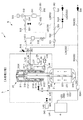
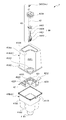
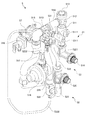
まず、図1〜図3を参照して、本実施形態に係る硬水軟化装置1を構成する各構成要素について説明する。本実施形態に係る硬水軟化装置1は、圧力タンク2と、流路制御バルブユニット3と、再生液供給ユニットとしての塩水供給ユニット4(図4〜図7も参照)と、配管ユニット5(図9〜図11も参照)と、筐体6と、中間パネル7(図8も参照)と、を備える。以下の説明において「ライン」とは、流路、経路、管路等の総称である。   First, with reference to FIGS. 1-3, each component which comprises the water softening apparatus 1 which concerns on this embodiment is demonstrated. The water softening apparatus 1 according to the present embodiment includes a pressure tank 2, a flow path control valve unit 3, a salt water supply unit 4 (see also FIGS. 4 to 7) as a regenerating liquid supply unit, and a piping unit 5 (FIG. 9 to FIG. 11), a housing 6, and an intermediate panel 7 (see also FIG. 8). In the following description, “line” is a general term for a flow path, a path, a pipeline, and the like.

[圧力タンク2]
圧力タンク2は、丸みを帯びた底部を有する筒状の耐圧容器(例えば、外周は平面視で略円形)であり、上部に開口21を有している。圧力タンク2の内部には、開口21の中央部から圧力タンク2の底部付近まで延びる集配液管231(図1参照)が設けられる。圧力タンク2の開口21において集配液管231を除く領域には、頂部スクリーン241が設けられる。集配液管231の下端部と圧力タンク2の底部との間には、底部スクリーン242が設けられる。そのため、集配液管231の上端部から圧力タンク2に流入した液体は、集配液管231内を下降して、その下端部から底部スクリーン242を通って集配液管231の外側に出て、集配液管231の外側における圧力タンク2の内部空間を上昇して、頂部スクリーン241を通って圧力タンク2から外に出る。反対に、頂部スクリーン241を通って圧力タンク2に流入した液体は、圧力タンク2の内部空間を下降して、底部スクリーン242を通って集配液管231の中に入り、集配液管231内を上昇して、その上端部から圧力タンク2の外に出る。なお、頂部スクリーン241及び底部スクリーン242は、その機能から、ディストリビュータやコレクタとも呼称される。
[Pressure tank 2]
The pressure tank 2 is a cylindrical pressure-resistant container (for example, the outer periphery is substantially circular in plan view) having a rounded bottom portion, and has an opening 21 at the top. Inside the pressure tank 2, a liquid collection / distribution pipe 231 (see FIG. 1) extending from the center of the opening 21 to the vicinity of the bottom of the pressure tank 2 is provided. A top screen 241 is provided in an area of the opening 21 of the pressure tank 2 excluding the liquid collection and distribution pipe 231. A bottom screen 242 is provided between the lower end of the liquid collection and distribution pipe 231 and the bottom of the pressure tank 2. Therefore, the liquid that has flowed into the pressure tank 2 from the upper end of the liquid collection / distribution pipe 231 descends in the liquid collection / distribution pipe 231 and exits from the lower end through the bottom screen 242 to the outside of the liquid collection / distribution pipe 231. The interior space of the pressure tank 2 outside the liquid pipe 231 rises and exits from the pressure tank 2 through the top screen 241. On the contrary, the liquid that has flowed into the pressure tank 2 through the top screen 241 descends the internal space of the pressure tank 2, enters the collection / distribution pipe 231 through the bottom screen 242, and enters the collection / distribution pipe 231. It rises and comes out of the pressure tank 2 from its upper end. The top screen 241 and the bottom screen 242 are also referred to as a distributor or a collector because of their functions.

集配液管231の外側における圧力タンク2の内部空間には、イオン交換樹脂ビーズ(典型的には水軟化に使用される陽イオン交換樹脂ビーズ)からなるイオン交換樹脂床211、及び濾過砂利からなる支持床212が収容される。支持床212は、圧力タンク2の底部側に配置される。支持床212は、イオン交換樹脂床211に対する流体の整流部材として機能する。イオン交換樹脂床211は、支持床212の上方に積層される。イオン交換樹脂床211は、原水(例えば、水道水)W1を導入することにより処理水としての軟水W2を製造する処理材として機能する。   The internal space of the pressure tank 2 outside the collection and distribution pipe 231 is composed of an ion exchange resin bed 211 made of ion exchange resin beads (typically cation exchange resin beads used for water softening), and filtered gravel. A support floor 212 is accommodated. The support floor 212 is disposed on the bottom side of the pressure tank 2. The support floor 212 functions as a fluid rectifying member for the ion exchange resin bed 211. The ion exchange resin bed 211 is laminated above the support floor 212. The ion exchange resin bed 211 functions as a treatment material for producing soft water W2 as treated water by introducing raw water (for example, tap water) W1.

[流路制御バルブユニット3]
流路制御バルブユニット3は、圧力タンク2の上部の開口21(図1参照)に取り付けられる。流路制御バルブユニット3は、圧力タンク2、塩水供給ユニット4及び配管ユニット5と接続されて、所要の運転動作に応じて流路を切り換える。
[Flow path control valve unit 3]
The flow path control valve unit 3 is attached to the upper opening 21 (see FIG. 1) of the pressure tank 2. The flow path control valve unit 3 is connected to the pressure tank 2, the salt water supply unit 4, and the piping unit 5, and switches the flow path according to a required operation.

図11に示すように、流路制御バルブユニット3は、バルブハウジング300と、後述するメインバルブ31、ブラインバルブ35、及びドレンバルブ36を駆動するための駆動機構(例えば、モータ、ギア、アーム、カム等から構成される駆動機構:図示省略)とを備えている。バルブハウジング300には、圧力タンク2の開口21に取り付けられる下部開口301と、原水流入ポート302と、処理水流出ポートとしての軟水流出ポート303と、再生液流入ポートとしての塩水流入ポート304と、ドレンポート305とが形成されている。原水流入ポート302及び軟水流出ポート303には、配管ユニット5のコネクタ57(後述)が取り付けられる。塩水流入ポート304には、第1管継手54a(後述)が接続される。ドレンポート305には、第1排水管551(後述)の一端が接続される。駆動機構は、防水カバー306により覆われる。   As shown in FIG. 11, the flow path control valve unit 3 includes a valve housing 300 and a driving mechanism (for example, a motor, a gear, an arm, and the like) for driving a main valve 31, a brine valve 35, and a drain valve 36, which will be described later. And a drive mechanism composed of a cam or the like (not shown). The valve housing 300 includes a lower opening 301 attached to the opening 21 of the pressure tank 2, a raw water inflow port 302, a soft water outflow port 303 as a treated water outflow port, a salt water inflow port 304 as a regenerated liquid inflow port, A drain port 305 is formed. A connector 57 (described later) of the piping unit 5 is attached to the raw water inflow port 302 and the soft water outflow port 303. A first pipe joint 54 a (described later) is connected to the salt water inflow port 304. One end of a first drain pipe 551 (described later) is connected to the drain port 305. The drive mechanism is covered with a waterproof cover 306.

流路制御バルブユニット3は、図1に示すように、メインバルブ31と、エゼクタ33と、ストレーナ34と、ブラインバルブ35と、ドレンバルブ36とを含んで構成されており、これらの要素は、バルブハウジング300に組み込まれている。更に、バルブハウジング300には、原水ラインL12と、軟水ラインL21、L22、L23、L24と、希釈水ラインL31、L32と、塩水ラインL42、L43、L44と、排水ラインL51、L52とが流体の輸送チャンネルとして形成されている。なお、軟水ラインL21〜L24、希釈水ラインL31、L32、塩水ラインL44は、原水ラインとしても機能する。軟水ラインL21は、塩水ラインとしても機能する。   The flow path control valve unit 3 includes a main valve 31, an ejector 33, a strainer 34, a brine valve 35, and a drain valve 36, as shown in FIG. It is incorporated in the valve housing 300. Further, the valve housing 300 includes a raw water line L12, soft water lines L21, L22, L23, L24, dilution water lines L31, L32, salt water lines L42, L43, L44, and drainage lines L51, L52. It is formed as a transport channel. The soft water lines L21 to L24, the dilution water lines L31 and L32, and the salt water line L44 also function as raw water lines. The soft water line L21 also functions as a salt water line.

メインバルブ31は、バルブハウジング300に形成された一端部が開口するシリンダ部311と、このシリンダ部311の内部に収容されるバルブ本体312とを備える。バルブ本体312は、シリンダ部311の軸線方向に沿って摺動可能に構成される。シリンダ部311は、その周壁に、軸線方向に沿って所定の間隔を隔てて4つの孔3111〜3114を備える。バルブ本体312は、3つのシール部3121〜3123を備える。3つのシール部3121〜3123は、軸線方向に沿って所定の間隔を隔てて周壁から外方へ張り出している。バルブ本体312は、その頂部に1つの孔3124を備える。   The main valve 31 includes a cylinder part 311 formed in the valve housing 300 and having one end opened, and a valve body 312 accommodated in the cylinder part 311. The valve body 312 is configured to be slidable along the axial direction of the cylinder portion 311. The cylinder portion 311 includes four holes 3111 to 3114 at a predetermined interval along the axial direction on the peripheral wall. The valve body 312 includes three seal portions 3121 to 3123. The three seal portions 3121 to 3123 protrude outward from the peripheral wall at a predetermined interval along the axial direction. The valve body 312 has one hole 3124 at the top.

バルブハウジング300の下部開口301が圧力タンク2の開口21に取り付けられると、流路制御バルブ31の開口端部は、圧力タンク2の集配液管231の上端部に水密に取り付けられる。原水ラインL12の一端は、バルブハウジング300の原水流入ポート302に接続される。原水ラインL12の他端は、シリンダ部311の第1孔3111に接続される。   When the lower opening 301 of the valve housing 300 is attached to the opening 21 of the pressure tank 2, the opening end of the flow path control valve 31 is attached to the upper end of the collection and distribution pipe 231 of the pressure tank 2 in a watertight manner. One end of the raw water line L12 is connected to the raw water inflow port 302 of the valve housing 300. The other end of the raw water line L12 is connected to the first hole 3111 of the cylinder portion 311.

軟水ラインL21の一端は、圧力タンク2の開口21において集配液管231を除く領域に水密に接続される。軟水ラインL21の他端は、軟水ラインL22の一端と、塩水ラインL44の一端との接続点に接続される。軟水ラインL22の他端は、シリンダ部311の第3孔3113に接続される。軟水ラインL23の一端は、シリンダ部311の第2孔3112に接続される。軟水ラインL23の他端は、軟水ラインL24の一端と、希釈水ラインL31の一端との接続点に接続される。軟水ラインL24の他端は、軟水流出ポート303に接続される。   One end of the soft water line L21 is watertightly connected to a region excluding the liquid collection and distribution pipe 231 at the opening 21 of the pressure tank 2. The other end of the soft water line L21 is connected to a connection point between one end of the soft water line L22 and one end of the salt water line L44. The other end of the soft water line L22 is connected to the third hole 3113 of the cylinder portion 311. One end of the soft water line L23 is connected to the second hole 3112 of the cylinder portion 311. The other end of the soft water line L23 is connected to a connection point between one end of the soft water line L24 and one end of the dilution water line L31. The other end of the soft water line L24 is connected to the soft water outflow port 303.

希釈水ラインL31の他端は、ストレーナ34の一側に接続される。ストレーナ34の他側には、希釈水ラインL32の一端が接続される。希釈水ラインL32の他端は、エゼクタ33のノズル側に接続される。エゼクタ33のディフューザ側には、塩水ラインL44の他端が接続される。エゼクタ33の吸込み口には、塩水ラインL43の一端が接続される。塩水ラインL43の他端は、ブラインバルブ35の一側に接続される。ブラインバルブ35の他側は、塩水流入ポート304と連絡される。   The other end of the dilution water line L31 is connected to one side of the strainer 34. One end of a dilution water line L32 is connected to the other side of the strainer 34. The other end of the dilution water line L32 is connected to the nozzle side of the ejector 33. The other end of the salt water line L44 is connected to the diffuser side of the ejector 33. One end of a salt water line L43 is connected to the suction port of the ejector 33. The other end of the salt water line L43 is connected to one side of the brine valve 35. The other side of the brine valve 35 is in communication with the salt water inflow port 304.

排水ラインL51の一端は、シリンダ部311の第4孔3114に接続される。排水ラインL51の他端は、ドレンバルブ36の一側に接続される。ドレンバルブ36の他側は、ドレンポート305と連絡される。   One end of the drain line L51 is connected to the fourth hole 3114 of the cylinder portion 311. The other end of the drain line L51 is connected to one side of the drain valve 36. The other side of the drain valve 36 is in communication with the drain port 305.

メインバルブ31は、採水及び再生に関して、原水W1を圧力タンク2の底部スクリーン242へ配液しながら、頂部スクリーン241で集液することにより原水W1の上昇流を生成して、軟水W2を製造する水処理工程の水(原水W1、軟水W2)の流れ、及び、再生液としての塩水W3を頂部スクリーン241へ配液しながら、底部スクリーン242で集液することにより塩水W3の下降流を生成して、イオン交換樹脂床211を再生させる再生工程の塩水W3の流れを、切り換え可能なバルブである。   The main valve 31 produces soft water W2 by collecting the raw water W1 to the bottom screen 242 of the pressure tank 2 while collecting the raw water W1 to the bottom screen 242 and collecting the raw water W1 with respect to sampling and regeneration. Water flow (raw water W1, soft water W2) in the water treatment process to be performed, and salt water W3 as a regenerating liquid is distributed to the top screen 241 and collected at the bottom screen 242 to generate a downward flow of the salt water W3. Thus, the flow of the salt water W3 in the regeneration process for regenerating the ion exchange resin bed 211 is a valve that can be switched.

(第1の状態)
図1に示すように、メインバルブ31において、バルブ本体312の第1シール部3121がシリンダ部311の第1孔3111と第2孔3112との間に位置するときに、バルブ本体312の第2シール部3122は、シリンダ部311の第3孔3113と第4孔3114との間に位置し、バルブ本体312の第3シール部3123は、シリンダ部311の第4孔3114と開口端部との間に位置する。このとき、シリンダ部311の第1孔3111は、シリンダ部311の周壁内面とバルブ本体312の周壁外面との間の所定の間隙、シリンダ部311の頂部内側の空間、及びバルブ本体312の頂部の孔3124を介して、バルブ本体312の内側の空間と連通する。即ち、シリンダ部311の第1孔3111は、圧力タンク2の集配液管231の上端部と連通する。バルブハウジング311の第2孔3112と第3孔3113とは、シリンダ部311の周壁内面とバルブ本体312の周壁外面との間の所定の間隙を介して、互いに連通する。シリンダ部311の第4孔3114は、他の孔又はバルブ本体312の内側の空間とは連通しない。以下、この位置関係を流路制御バルブ31の「第1の状態」という。
(First state)
As shown in FIG. 1, in the main valve 31, when the first seal portion 3121 of the valve body 312 is positioned between the first hole 3111 and the second hole 3112 of the cylinder portion 311, The seal portion 3122 is located between the third hole 3113 and the fourth hole 3114 of the cylinder portion 311, and the third seal portion 3123 of the valve body 312 is formed between the fourth hole 3114 of the cylinder portion 311 and the opening end portion. Located between. At this time, the first hole 3111 of the cylinder portion 311 has a predetermined gap between the inner surface of the peripheral wall of the cylinder portion 311 and the outer peripheral surface of the valve body 312, the space inside the top portion of the cylinder portion 311, and the top portion of the valve body 312. It communicates with the space inside the valve body 312 through the hole 3124. That is, the first hole 3111 of the cylinder portion 311 communicates with the upper end portion of the liquid collection and distribution pipe 231 of the pressure tank 2. The second hole 3112 and the third hole 3113 of the valve housing 311 communicate with each other via a predetermined gap between the inner surface of the peripheral wall of the cylinder portion 311 and the outer surface of the peripheral wall of the valve body 312. The fourth hole 3114 of the cylinder portion 311 does not communicate with other holes or the space inside the valve body 312. Hereinafter, this positional relationship is referred to as a “first state” of the flow path control valve 31.

メインバルブ31には、他に、第2の状態、第3の状態及び第4の状態がある。これらについては、本願と同一出願人による特願2016−018129における第2の状態、第3の状態及び第4の状態に関する説明をそれぞれ援用することにより、本明細書での詳細な説明を省略する。   In addition, the main valve 31 has a second state, a third state, and a fourth state. About these, the detailed description in this specification is abbreviate | omitted by using the description regarding the 2nd state in the Japanese Patent Application No. 2006-018129 by the same applicant as this application, the 3rd state, and the 4th state, respectively. .

[配管ユニット5]
図1に示すように、流路制御バルブユニット3には、原水導入部510から(後述するコネクタ57を介して)原水流入ポート302に至る原水ラインL11、及び軟水流出ポート303から(コネクタ57を介して)軟水導出部520に至る軟水ラインL25が接続される。原水ラインL11と軟水ラインL25とは、バイパスラインL61で接続される。原水ラインL11は、原水配管51から構成される。軟水ラインL25は、軟水配管52から構成される。バイパスラインL61は、バイパス配管53から構成される。
[Piping unit 5]
As shown in FIG. 1, the flow path control valve unit 3 includes a raw water line L11 extending from the raw water inlet 510 to the raw water inlet port 302 (via a connector 57 described later), and a soft water outlet port 303 (connector 57). A soft water line L25 leading to the soft water outlet 520 is connected. The raw water line L11 and the soft water line L25 are connected by a bypass line L61. The raw water line L <b> 11 includes a raw water pipe 51. The soft water line L25 includes a soft water pipe 52. The bypass line L61 includes a bypass pipe 53.

配管ユニット5は、原水配管51と、処理水配管としての軟水配管52と、バイパス配管53と、第1のバイパス切替弁515と、第2のバイパス切替弁531と、後述する様々な弁群と、を含む組立体である。よって、配管ユニット5は、原水導入部510、及び処理水導出部としての軟水導出部520を備える。   The piping unit 5 includes a raw water pipe 51, a soft water pipe 52 as a treated water pipe, a bypass pipe 53, a first bypass switching valve 515, a second bypass switching valve 531, and various valve groups described later. The assembly including. Therefore, the piping unit 5 includes a raw water introducing unit 510 and a soft water deriving unit 520 as a treated water deriving unit.

図9、図11に示すように、配管ユニット5は、原水配管51及び軟水配管52を流路制御バルブユニット3に接続するための一体成形されたコネクタ57を備える。このコネクタ57は、原水配管51が接続される第1ポート571と、第1ポート571と連通し、原水流入ポート302と接続される第2ポート572と、軟水流出ポート303と接続される第3ポート573と、第3ポート573と連通し、軟水配管52が接続される第4ポート574と、を備える。第1ポート571と第2ポート572との中間位置には、原水流路としての中間ポート575が設けられる。中間ポート575には、後述する圧力逃し弁518が接続される。即ち、圧力逃し弁518は、原水配管51に代えて、第1ポート571と第2ポート572とを連通する中間ポート575に接続される。   As shown in FIGS. 9 and 11, the piping unit 5 includes an integrally formed connector 57 for connecting the raw water piping 51 and the soft water piping 52 to the flow path control valve unit 3. The connector 57 communicates with the first port 571 to which the raw water pipe 51 is connected, the second port 572 connected to the raw water inflow port 302, and the third port connected to the soft water outflow port 303. A port 573 and a fourth port 574 that communicates with the third port 573 and is connected to the soft water pipe 52 are provided. An intermediate port 575 serving as a raw water flow path is provided at an intermediate position between the first port 571 and the second port 572. A pressure relief valve 518 described later is connected to the intermediate port 575. That is, the pressure relief valve 518 is connected to an intermediate port 575 that communicates the first port 571 and the second port 572 instead of the raw water pipe 51.

図1及び図9に示すように、原水ラインL11(原水配管51)には、原水導入部510に近い側から順に、原水ストレーナ511、フィルタ513を有する真空逃し弁512、逆止め弁514、第1のバイパス切替弁515、減圧弁516、フロースイッチ517、圧力逃し弁518が設けられる。原水ストレーナ511は、原水W1に含まれる微細粒子の流通を阻止する。真空逃し弁512は、系内での負圧発生時に開弁して大気を吸入する。逆止め弁514は、原水W1の流れを一方向に規制して原水W1の逆流を防止する。   As shown in FIGS. 1 and 9, the raw water line L11 (raw water pipe 51) includes, in order from the side close to the raw water introduction section 510, a raw water strainer 511, a vacuum relief valve 512 having a filter 513, a check valve 514, 1 bypass switching valve 515, pressure reducing valve 516, flow switch 517, and pressure relief valve 518 are provided. The raw water strainer 511 prevents the distribution of fine particles contained in the raw water W1. The vacuum relief valve 512 is opened when a negative pressure is generated in the system and sucks air. The check valve 514 regulates the flow of the raw water W1 in one direction to prevent the backflow of the raw water W1.

第1のバイパス切替弁515は、第2のバイパス切替弁531と協働して、原水ラインL11と後述するバイパスラインL61との間で入口流路を切替える。減圧弁516は、原水W1を所定の水圧まで減圧する。フロースイッチ517は、所定流量の原水W1が流通したことを検知すると、検出信号を後述する制御ボックス73の電子機器731に出力する。圧力逃し弁518は、原水W1の水圧や硬水軟化装置1の二次側からの背圧が所定値以上になった場合に、過剰な圧力を系外に逃がすことにより、圧力タンク2や流路制御バルブユニット3を保護する。   The first bypass switching valve 515 switches the inlet flow path between the raw water line L11 and a later-described bypass line L61 in cooperation with the second bypass switching valve 531. The pressure reducing valve 516 reduces the raw water W1 to a predetermined water pressure. When the flow switch 517 detects that the raw water W1 having a predetermined flow rate has circulated, the flow switch 517 outputs a detection signal to the electronic device 731 of the control box 73 described later. The pressure relief valve 518 allows the excess pressure to escape outside the system when the water pressure of the raw water W1 or the back pressure from the secondary side of the water softening device 1 exceeds a predetermined value. The control valve unit 3 is protected.

軟水ラインL25(軟水配管52)には、流路制御バルブユニット3に近い側から順に、逆止め弁521、処理水ストレーナとしての軟水ストレーナ522、切替弁523が設けられる。逆止め弁521は、軟水W2の流れを一方向に規制して軟水W2の逆流を防止する。軟水ストレーナ522は、軟水W2に混入した異物(イオン交換樹脂の細粒や破砕片)を捕捉可能であり、検水コック5221を開けることによりその異物を、ストレーナ排出管5222(ストレーナ排出ラインL62)を介して系外に排出する。   In the soft water line L25 (soft water pipe 52), a check valve 521, a soft water strainer 522 as a treated water strainer, and a switching valve 523 are provided in this order from the side close to the flow path control valve unit 3. The check valve 521 prevents the back flow of the soft water W2 by restricting the flow of the soft water W2 in one direction. The soft water strainer 522 can capture foreign matter (fine particles or crushed pieces of ion exchange resin) mixed in the soft water W2, and the foreign matter is removed by opening the water inspection cock 5221 to the strainer discharge pipe 5222 (strainer discharge line L62). Through the system.

原水ラインL11(原水配管51)の逆止め弁514と第1のバイパス切替弁515との接続点と、軟水ラインL25(軟水配管52)の切替弁523の下流側との間には、バイパスラインL61が接続される。バイパスラインL61は、原水配管51と軟水配管52とを接続するバイパス配管53を構成する。原水配管51からのバイパス配管53の分岐部は、逆止め弁514と減圧弁516との間に配置される。バイパスラインL61(バイパス配管53)には、原水ラインL11に近い側から順に、第2のバイパス切替弁531、逆止め弁532が設けられる。   Between the connection point between the check valve 514 of the raw water line L11 (raw water pipe 51) and the first bypass switching valve 515 and the downstream side of the switching valve 523 of the soft water line L25 (soft water pipe 52), a bypass line is provided. L61 is connected. The bypass line L61 constitutes a bypass pipe 53 that connects the raw water pipe 51 and the soft water pipe 52. A branch portion of the bypass pipe 53 from the raw water pipe 51 is disposed between the check valve 514 and the pressure reducing valve 516. In the bypass line L61 (bypass pipe 53), a second bypass switching valve 531 and a check valve 532 are provided in order from the side closer to the raw water line L11.

第2のバイパス切替弁531は、第1のバイパス切替弁515と協働して入口流路を切替えると共に、切替弁523と協働して出口流路を切替える。具体的には、第1のバイパス切替弁515を開放し、且つ第2のバイパス切替弁531を閉止すると、原水W1は、バイパス配管53には流入せずに、流路制御バルブユニット3に流入する。反対に、第1のバイパス切替弁515を閉止し、且つ第2のバイパス切替弁531を開放すると、原水W1は、流路制御バルブユニット3には流入せずに、バイパス配管53に流入する。   The second bypass switching valve 531 switches the inlet flow path in cooperation with the first bypass switching valve 515 and switches the outlet flow path in cooperation with the switching valve 523. Specifically, when the first bypass switching valve 515 is opened and the second bypass switching valve 531 is closed, the raw water W1 does not flow into the bypass pipe 53 but flows into the flow path control valve unit 3. To do. On the contrary, when the first bypass switching valve 515 is closed and the second bypass switching valve 531 is opened, the raw water W1 flows into the bypass pipe 53 without flowing into the flow path control valve unit 3.

例えば、イオン交換樹脂床211の交換や流路制御バルブユニット3の修理を行う際には、流路制御バルブユニット3及び圧力タンク2への水の流れを止める一方で、硬水軟化装置1を設置した家屋の室内への給水は継続する必要がある。そのため、この場合には、第2のバイパス切替弁531を開放し、且つ第1のバイパス切替弁515及び切替弁523を閉止した状態で、メンテナンスを行う。   For example, when the ion exchange resin bed 211 is replaced or the flow path control valve unit 3 is repaired, the water softening device 1 is installed while the flow of water to the flow path control valve unit 3 and the pressure tank 2 is stopped. It is necessary to continue water supply to the house. Therefore, in this case, maintenance is performed with the second bypass switching valve 531 open and the first bypass switching valve 515 and the switching valve 523 closed.

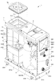
図3に示すように、原水配管51、軟水配管52及びバイパス配管53を含む配管ユニット5の組立体は、圧力タンク2の上方及び側方に亘って配置される。圧力タンク2の外周は平面視で略円形であり、配管ユニット5は、圧力タンク2の円形の外周に沿って配置される。   As shown in FIG. 3, the assembly of the
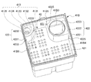
 piping unit 5 including the raw water piping 51, the soft water piping 52, and the bypass piping 53 is arranged over and over the pressure tank 2. The outer periphery of the pressure tank 2 is substantially circular in plan view, and the piping unit 5 is disposed along the circular outer periphery of the pressure tank 2.

[塩水供給ユニット4]
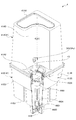
塩水供給ユニット4は、主として、図4〜図7に示されるように、圧力タンク2内のイオン交換樹脂床211に対して、原料薬剤としての塩Sから生成した塩水W3を供給する。塩水供給ユニット4は、再生液タンクとしての塩水タンク41と、再生液プレートとしての塩水プレート42と、再生液流通管としての塩水バルブパイプ43と、再生液バルブとしての塩水バルブ44と、を備えて構成される。塩水タンク41は、塩Sを収容可能な原料収容部411と、塩Sと補給水とから生成される塩水W3を貯留可能な再生液貯留部としての塩水貯留部412とを有する。塩水プレート42は、塩水タンク41の内部に配置され、塩Sが載置される載置面421を有する。塩水バルブパイプ43には、塩水タンク41から導出される塩水W3又は塩水タンク41に導入される補給水が流通する。塩水バルブ44は、塩水バルブパイプ43と接続され、補給水の流れ及び塩水W3の流れを制御すると共に、塩水タンク41内の水位が予め設定された規定水位WL(図7参照)に達した場合に補給水の流れを遮断する機能を有する。塩水バルブ44、塩水バルブパイプ43、及び後述する上方覆い部としての閉塞部材4224は、塩水バルブ組立体(再生液バルブ組立体)45として一体に組み立てられる。
[Salt water supply unit 4]
The salt water supply unit 4 mainly supplies salt water W3 generated from the salt S as the raw material drug to the ion exchange resin bed 211 in the pressure tank 2 as shown in FIGS. The salt water supply unit 4 includes a salt water tank 41 as a regenerating liquid tank, a salt water plate 42 as a regenerating liquid plate, a salt water valve pipe 43 as a regenerating liquid circulation pipe, and a salt water valve 44 as a regenerating liquid valve. Configured. The salt water tank 41 includes a raw material storage unit 411 that can store the salt S, and a salt water storage unit 412 as a regenerative liquid storage unit that can store the salt water W3 generated from the salt S and makeup water. The salt water plate 42 is disposed inside the salt water tank 41 and has a placement surface 421 on which the salt S is placed. In the salt water valve pipe 43, salt water W3 led out from the salt water tank 41 or makeup water introduced into the salt water tank 41 circulates. The salt water valve 44 is connected to the salt water valve pipe 43 and controls the flow of makeup water and the flow of the salt water W3, and the water level in the salt water tank 41 reaches a preset specified water level WL (see FIG. 7). Has the function of blocking the flow of makeup water. The salt water valve 44, the salt water valve pipe 43, and a closing member 4224 as an upper cover portion described later are integrally assembled as a salt water valve assembly (regeneration liquid valve assembly) 45.

塩水タンク41は、上部タンク41Aと、下部タンク41Bとに分割される。上部タンク41A及び下部タンク41Bを上下方向に連結することにより、塩水タンク41は、一体に構成される。下部タンク41Bは、概して角筒状の筒状体である。下部タンク41Bの底部は、塩水バルブ44が設置される領域に対応する第1底部41B1と、第1底部41B1よりも高い位置に設定され、塩水W3の供給停止位置BL(図7参照)に対応する第2底部41B2とで構成される。第1底部41B1は、下部タンク41Bの1つのコーナー部の近傍に配置される。第1底部41B1は、塩水タンク41が硬水軟化装置1の所定位置に設置されるときに、硬水軟化装置1の前面側に位置する。   The salt water tank 41 is divided into an upper tank 41A and a lower tank 41B. The salt water tank 41 is integrally formed by connecting the upper tank 41A and the lower tank 41B in the vertical direction. The lower tank 41B is a generally rectangular tubular body. The bottom of the lower tank 41B is set to a position that is higher than the first bottom 41B1 and the first bottom 41B1 corresponding to the region where the salt water valve 44 is installed, and corresponds to the salt water W3 supply stop position BL (see FIG. 7). And the second bottom portion 41B2. The first bottom portion 41B1 is disposed in the vicinity of one corner portion of the lower tank 41B. The first bottom 41B1 is located on the front side of the water softening device 1 when the salt water tank 41 is installed at a predetermined position of the water softening device 1.

下部タンク41Bには、下部タンク41Bの第2底部41B2から所定の高さに段部41B3が設けられる。段部41B3は、これよりも上方における下部タンク41Bの横断面の大きさに比べて、これよりも下方における下部タンク41Bの横断面の大きさが小さくなった段部である。下部タンク41Bの内部において、この段部41B3の上に、塩水プレート42が配置される。塩水プレート42には、塩Sが載置される。下部タンク41Bにおいて、塩水プレート42の載置面421を境界として、載置面421よりも下方は、塩水貯留部412として機能する。一方、境界よりも上方は、原料収容部411として機能する。   The lower tank 41B is provided with a step 41B3 at a predetermined height from the second bottom 41B2 of the lower tank 41B. The step portion 41B3 is a step portion in which the size of the cross section of the lower tank 41B below the lower tank 41B is smaller than the size of the cross section of the lower tank 41B above the step portion 41B3. Inside the lower tank 41B, a salt water plate 42 is disposed on the step 41B3. The salt S is placed on the salt water plate 42. In the lower tank 41 </ b> B, the lower surface than the mounting surface 421 functions as a salt water storage unit 412 with the mounting surface 421 of the salt water plate 42 as a boundary. On the other hand, the part above the boundary functions as a raw material container 411.

上部タンク41Aは、専ら原料収容部411として機能する。これは、塩水タンク41が有する原料収容部411及び塩水貯留部412のうち、上部タンク41Aは、原料収容部411としての機能のみを果たし、塩水貯留部412としての機能は果たさない、という意味である。原料収容部411と塩水貯留部412との境界は、塩水プレート42の載置面421によって決められる。塩水プレート42は、下部タンク41Bの内部に配置される。そのため、下部タンク41Bは、塩水貯留部412としての機能を果たすだけでなく、原料収容部411としての機能も一部果たす。従って、上部タンク41Aは、専ら原料収容部411として機能することになる。   The upper tank 41A functions exclusively as the raw material container 411. This means that among the raw material storage unit 411 and the salt water storage unit 412 of the salt water tank 41, the upper tank 41A serves only as the raw material storage unit 411 and does not function as the salt water storage unit 412. is there. The boundary between the raw material container 411 and the salt water reservoir 412 is determined by the placement surface 421 of the salt water plate 42. The salt water plate 42 is disposed inside the lower tank 41B. Therefore, the lower tank 41 </ b> B not only functions as the salt water storage unit 412 but also partially functions as the raw material storage unit 411. Therefore, the upper tank 41A functions exclusively as the raw material storage unit 411.

図6に示すように、塩水タンク41には、原料収容部411と連通する開口4133を介して内部の過剰な塩水W3を外部に排出するオーバーフロー部413が設けられる。オーバーフロー部413は、下部タンク41Bの内部に配置される。具体的には、下部タンク41Bの第1底部41B1が形成されているコーナー部とは異なるコーナー部には、段部41B3から所定の高さにオーバーフロー部413が設けられる。即ち、オーバーフロー部413が設けられる下部タンク41Bのコーナー部には、第2底部41B2からオーバーフロー高さまで下部タンク41Bの横方向内側に凹んだ凹部4131を備える。凹部4131の上面は、開口4133を有するオーバーフロー面4132を構成する。オーバーフロー面4132には、開口4133から下向きに延びる筒状の排水筒4134が設けられる。排水筒4134の底部開口4135には、第2排水管552の一端が接続される。第2排水管552の他端は、共用排水管554に接続される。   As shown in FIG. 6, the salt water tank 41 is provided with an overflow portion 413 that discharges excess salt water W3 inside through an opening 4133 communicating with the raw material storage portion 411. The overflow part 413 is disposed inside the lower tank 41B. Specifically, an overflow portion 413 is provided at a predetermined height from the step portion 41B3 at a corner portion different from the corner portion where the first bottom portion 41B1 of the lower tank 41B is formed. That is, the corner portion of the lower tank 41B where the overflow portion 413 is provided is provided with a recess 4131 that is recessed inward in the lateral direction of the lower tank 41B from the second bottom portion 41B2 to the overflow height. The upper surface of the recess 4131 constitutes an overflow surface 4132 having an opening 4133. The overflow surface 4132 is provided with a cylindrical drain tube 4134 extending downward from the opening 4133. One end of the second drain pipe 552 is connected to the bottom opening 4135 of the drain cylinder 4134. The other end of the second drain pipe 552 is connected to the common drain pipe 554.

塩水プレート42は、載置面421よりも隆起し、塩水バルブ44における載置面421よりも上方に位置する部分を覆う再生液バルブ用隆起部としての塩水バルブ用隆起部422と、載置面421よりも隆起し、オーバーフロー部413の開口4133を覆うオーバーフロー部用隆起部423と、を備える。即ち、塩水バルブ用隆起部422は、塩水プレート42に連結され且つ塩水バルブ44における載置面421よりも上方に位置する部分を側方から覆う側方覆い部4221と、塩水バルブ44における載置面421よりも上方に位置する部分を上方から覆う上方覆い部4222及び4224とで構成される。側方覆い部4221(及びこれと一体の上方覆い部4222)と、上方覆い部4224とは、分離自在に構成される。   The salt water plate 42 protrudes from the mounting surface 421 and covers the portion of the salt water valve 44 that is located above the mounting surface 421. And an overflow portion bulge portion 423 that is higher than 421 and covers the opening 4133 of the overflow portion 413. That is, the salt water valve bulge 422 is connected to the salt water plate 42 and has a side cover 4221 that covers a portion of the salt water valve 44 located above the placement surface 421 from the side, and the salt water valve 44 placement. It is comprised by the upper cover parts 4222 and 4224 which cover the part located above the surface 421 from upper direction. The side cover portion 4221 (and the upper cover portion 4222 integrated with the side cover portion 4221) and the upper cover portion 4224 are configured to be separable.

具体的には、塩水バルブ用隆起部422は、下部タンク41Bの第1底部41B1に設置した塩水バルブ44を実質的に収容する所定の高さまで載置面421よりも隆起する。塩水バルブ用隆起部422は、側方覆い部としての隔壁4221と、上方覆い部としての隔板4222及び閉塞部材4224とで構成される。即ち、隔壁4221は、下部タンク41Bの第1底部41B1が配置されるコーナー部の近傍において、第1底部41B1に設置した塩水バルブ44をこのコーナー部の近傍領域内に隔離するように、このコーナー部を構成する下部タンク41Bの第1の側壁41B4から隣接する第2の側壁41B5までを所要の高さで覆う。隔板4222は、隔壁4221の上縁に連なり、下部タンク41Bの第1の側壁41B4及び第2の側壁41B5に対して実質的に接する領域を覆う。隔板4222には、下部タンク41Bの第1底部41B1の真上位置に、例えば円形の開口4223が設けられる。上方覆い部としての閉塞部材4224は、隔板4222の開口4223を、上部タンク41Aの開口41A3とともに一体的に閉塞する。   Specifically, the salt water valve bulge 422 bulges from the mounting surface 421 to a predetermined height that substantially accommodates the salt water valve 44 installed at the first bottom 41B1 of the lower tank 41B. The salinity valve bulge portion 422 includes a partition wall 4221 as a side cover portion, and a partition plate 4222 and a closing member 4224 as upper cover portions. That is, the partition wall 4221 has a corner in the vicinity of the corner where the first bottom 41B1 of the lower tank 41B is disposed so that the salt water valve 44 installed in the first bottom 41B1 is isolated in the vicinity of the corner. Covering from the first side wall 41B4 of the lower tank 41B constituting the part to the adjacent second side wall 41B5 at a required height. The partition plate 4222 continues to the upper edge of the partition wall 4221 and covers a region substantially in contact with the first side wall 41B4 and the second side wall 41B5 of the lower tank 41B. In the partition plate 4222, for example, a circular opening 4223 is provided at a position directly above the first bottom 41B1 of the lower tank 41B. A closing member 4224 serving as an upper cover integrally closes the opening 4223 of the partition plate 4222 together with the opening 41A3 of the upper tank 41A.

オーバーフロー部用隆起部423は、塩水プレート42の載置面421よりも隆起し、オーバーフロー部413のオーバーフロー面4132及び開口4133を覆う。具体的には、オーバーフロー部用隆起部423は、塩水バルブ用隆起部422と実質的に同程度の高さまで載置面421よりも隆起する。オーバーフロー部用隆起部423は、側方覆い部としての隔壁4231と、上方覆い部としての隔板4232とで構成される。具体的には、隔壁4231は、下部タンク41Bのオーバーフロー部413が設けられたコーナー部を隔離するように、このコーナー部を構成する第2の側壁41B5から隣接する第3の側壁41B6までを所要の高さで覆う。隔板4232は、隔壁4231の上縁に連なり、下部タンク41Bの第2の側壁41B5及び第3の側壁41B6に対して実質的に接する領域を覆う。   The overflow portion raised portion 423 rises from the mounting surface 421 of the salt water plate 42 and covers the overflow surface 4132 and the opening 4133 of the overflow portion 413. Specifically, the overflow portion raised portion 423 rises from the placement surface 421 to a height substantially the same as the salt water valve raised portion 422. The overflow portion raised portion 423 includes a partition wall 4231 as a side cover portion and a partition plate 4232 as an upper cover portion. Specifically, the partition wall 4231 requires from the second side wall 41B5 constituting the corner portion to the adjacent third side wall 41B6 so as to isolate the corner portion where the overflow portion 413 of the lower tank 41B is provided. Cover with the height of. The partition plate 4232 is connected to the upper edge of the partition wall 4231 and covers a region substantially in contact with the second side wall 41B5 and the third side wall 41B6 of the lower tank 41B.

図6、図7に示すように、塩水バルブ用隆起部422の側端縁と、塩水タンク41の内壁(第1の側壁41B4及び第2の側壁41B5)との間には、間隙4225が設けられる。この間隙4225は、塩Sが補給水に溶解する際に生じる塩水貯留部412の濃度差に起因する対流の流路として機能する。オーバーフロー部用隆起部423の側端縁と、塩水タンク41の内壁(第2の側壁41B5及び第3の側壁41B6)との間には、間隙4233が設けられる。この間隙4233は、塩水貯留部412の適正液量を超えて原料収容部411の規定位置まで増えた塩水をオーバーフロー部413のオーバーフロー面4132から排出する流路として機能する。その一方で、この間隙4233は、塩Sが補給水に溶解する際に生じる塩水貯留部412の濃度差に起因する対流の流路としても機能する。   As shown in FIGS. 6 and 7, a gap 4225 is provided between the side edge of the salt water valve bulge 422 and the inner wall of the salt water tank 41 (first side wall 41B4 and second side wall 41B5). It is done. The gap 4225 functions as a convection flow path resulting from a difference in concentration of the salt water reservoir 412 that occurs when the salt S is dissolved in the makeup water. A gap 4233 is provided between the side edge of the overflow ridge 423 and the inner wall (second side wall 41B5 and third side wall 41B6) of the salt water tank 41. The gap 4233 functions as a flow path for discharging salt water that has exceeded the appropriate amount of liquid in the salt water storage unit 412 and has reached the specified position of the raw material storage unit 411 from the overflow surface 4132 of the overflow unit 413. On the other hand, the gap 4233 also functions as a convection flow path due to a difference in concentration of the salt water reservoir 412 that occurs when the salt S is dissolved in the makeup water.

上部タンク41Aは、塩水バルブ用隆起部422の上方に、原料収容部411とはタンク壁41A5を介して区画され、少なくとも上方に開放する開放空間41A1を有する。この開放空間41A1には、塩水バルブパイプ43が配置される。具体的には、上部タンク41Aは、下部タンク41Bの筒状体に対応する筒状体とは一部異なる。即ち、下部タンク41Bの第1底部41B1の真上に位置する上部タンク41Aの部分は、上部タンク41Aの高さを通じて上部タンク41Aの横方向及び下方向の内側に凹んだ開放空間としての凹部41A1を備える。凹部41A1の最下部には、上部タンク41Aの他の部分と一体に連なる底板41A2が設けられる。底板41A2には、下部タンク41Bの第1底部41B1の真上位置に、例えば円形の開口41A3が設けられる。上部タンク41Aの上面には、原料薬剤(塩)を導入するための原料導入口41A4が設けられる。   The upper tank 41A has an open space 41A1 that is partitioned above the salt water valve bulge 422 and separated from the raw material container 411 via a tank wall 41A5 and opens upward. A salt water valve pipe 43 is disposed in the open space 41A1. Specifically, the upper tank 41A is partially different from the cylindrical body corresponding to the cylindrical body of the lower tank 41B. That is, the portion of the upper tank 41A located directly above the first bottom portion 41B1 of the lower tank 41B is a recess 41A1 as an open space that is recessed in the lateral and downward directions of the upper tank 41A through the height of the upper tank 41A. Is provided. A bottom plate 41A2 is provided at the lowermost portion of the recess 41A1 so as to be integrated with other parts of the upper tank 41A. In the bottom plate 41A2, for example, a circular opening 41A3 is provided at a position directly above the first bottom portion 41B1 of the lower tank 41B. On the upper surface of the upper tank 41A, a raw material inlet 41A4 for introducing a raw chemical (salt) is provided.

塩水バルブパイプ43は、塩水タンク41から導出される塩水W3又は塩水タンク41に導入される補給水が流通する。具体的には、塩水バルブパイプ43は、例えば再生工程において、貯留する塩水W3を圧力タンク2に供給するための塩水ラインL41の一部を構成する。塩水W3は、陽イオン交換樹脂ビーズを用いる硬水軟化装置1においては、塩化ナトリウム、塩化カリウムの各水溶液等を利用することができる。   In the salt water valve pipe 43, salt water W3 led out from the salt water tank 41 or makeup water introduced into the salt water tank 41 circulates. Specifically, the salt water valve pipe 43 constitutes a part of a salt water line L41 for supplying the salt water W3 to be stored to the pressure tank 2 in, for example, a regeneration process. In the water softening apparatus 1 using cation exchange resin beads, the salt water W3 can use aqueous solutions of sodium chloride and potassium chloride.

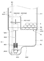
図7に示すように、塩水タンク41の内部は、塩水プレート42により、原料収容部411と、塩水貯留部412とに区画される。原料収容部411は、再生液の原料としての塩S(例えば、塩化ナトリウムや塩化カリウム)を収容可能な領域である。塩水貯留部412は、原料収容部411に収容された塩Sと外部から導入される補給水とから生成される塩水W3を貯留可能な領域である。   As shown in FIG. 7, the inside of the salt water tank 41 is partitioned into a raw material storage unit 411 and a salt water storage unit 412 by a salt water plate 42. The raw material storage unit 411 is a region that can store a salt S (for example, sodium chloride or potassium chloride) as a raw material of the regenerated liquid. The salt water storage part 412 is an area | region which can store the salt water W3 produced | generated from the salt S accommodated in the raw material accommodating part 411 and the supplementary water introduce | transduced from the outside.

塩水プレート42には、原料収容部411に収容される塩Sが載置される。塩水プレート42に載置された塩Sの一部は、塩水プレート42を通じて塩水貯留部412に溶け出し、補給水と混じり合うことにより塩水W3となる。塩水バルブ44の下部は、塩水タンク41の第1底部41B1に設置される。第1底部41B1の横断面積は、例えば、塩水バルブ44の下部の面積の1.2倍以下であることが好ましい。第2底部41B2の高さは、例えば、塩水の供給停止位置BLよりも2〜5cm低いことが好ましい。   The salt S accommodated in the raw material accommodating part 411 is mounted on the salt water plate 42. A part of the salt S placed on the salt water plate 42 is dissolved into the salt water storage part 412 through the salt water plate 42 and mixed with makeup water to become salt water W3. The lower part of the salt water valve 44 is installed in the first bottom 41B1 of the salt water tank 41. The cross-sectional area of the first bottom 41B1 is preferably 1.2 times or less the area under the salt water valve 44, for example. For example, the height of the second bottom portion 41B2 is preferably 2 to 5 cm lower than the salt water supply stop position BL.

塩水バルブ44は、流路制御バルブユニット3からの補給水の流れ及び流路制御バルブユニット3への塩水W3の流れを制御すると共に、塩水タンク41内の水位が予め設定された規定水位WLに達した場合に補給水の流れを遮断する機能を有する。塩水バルブ44は、水位検出用フロート4401と、フロートロッド4404と、塩水バルブパイプ43と、エアチェックハウジング部4420と、を備える。水位検出用フロート4401は、塩水タンク41の内部に貯留された塩水W3の水位を検出する。水位検出用フロート4401は、垂直断面において逆凹形となる円筒状に形成される。水位検出用フロート4401は、補給水よりも比重の小さい材料により構成される。そのため、水位検出用フロート4401は、補給水及び塩水W3に対して浮力を有する。フロートロッド4404は、水位検出用フロート4401に連動して上下に移動する棒状の部材である。フロートロッド4404の上端は、水位検出用フロート4401に連結される。フロートロッド4404の下端は、弁体としての補水ストッパ(図示せず)に連結される。   The salt water valve 44 controls the flow of makeup water from the flow path control valve unit 3 and the flow of salt water W3 to the flow path control valve unit 3, and the water level in the salt water tank 41 is set to a preset specified water level WL. When it reaches, it has a function to block the flow of makeup water. The salt water valve 44 includes a water level detection float 4401, a float rod 4404, a salt water valve pipe 43, and an air check housing part 4420. The water level detection float 4401 detects the water level of the salt water W3 stored in the salt water tank 41. The water level detection float 4401 is formed in a cylindrical shape having a reverse concave shape in a vertical section. The water level detection float 4401 is made of a material having a specific gravity smaller than that of makeup water. Therefore, the water level detection float 4401 has buoyancy with respect to the makeup water and the salt water W3. The float rod 4404 is a rod-shaped member that moves up and down in conjunction with the water level detection float 4401. The upper end of the float rod 4404 is connected to the water level detection float 4401. The lower end of the float rod 4404 is connected to a water replenishing stopper (not shown) as a valve body.

塩水バルブパイプ43は、塩水タンク41から外部に供給される塩水W3、及び外部から塩水タンク41に供給される補給水が流通する筒状の部材である。塩水バルブパイプ43の下方の端部は、下部エアチェックハウジング(図示せず)に接続される。エアチェックハウジング部4420は、塩水バルブフィルタ4421と、上部エアチェックハウジングと、補水ストッパと、ボールホルダと、フロートボールと、下部エアチェックハウジングと、金属ボールと、プラグと、を備える。エアチェックハウジング部4420の詳細を含む塩水バルブ44の構成及び作用については、本願と同一出願人による特開2015−174074号公報を援用することにより、本明細書での詳細な説明を省略する。   The salt water valve pipe 43 is a cylindrical member through which salt water W3 supplied from the salt water tank 41 to the outside and makeup water supplied from the outside to the salt water tank 41 flow. The lower end of the salt water valve pipe 43 is connected to a lower air check housing (not shown). The air check housing part 4420 includes a salt water valve filter 4421, an upper air check housing, a water replenishing stopper, a ball holder, a float ball, a lower air check housing, a metal ball, and a plug. About the structure and effect | action of the salt water valve 44 including the detail of the air check housing part 4420, detailed description in this specification is abbreviate | omitted by using Unexamined-Japanese-Patent No. 2015-174074 by the same applicant as this application.

図4、図5に示すように、塩水バルブ組立体45は、塩水バルブ44と、塩水バルブパイプ43と、塩水プレート42の塩水バルブ用隆起部422の閉塞部材4224とが一体に構成される。塩水バルブパイプ43の先端には、塩水配管54の第3接続用端部543が接続される。塩水バルブパイプ43を上方に引き上げると、閉塞部材4224及び塩水バルブ44は、共に引き上げられる。塩水タンク41の原料導入口41A4の閉鎖については、後述する。   As shown in FIGS. 4 and 5, the salt water valve assembly 45 includes a salt water valve 44, a salt water valve pipe 43, and a blocking member 4224 of the salt water valve bulge 422 of the salt water plate 42. A third connection end 543 of the salt water pipe 54 is connected to the tip of the salt water valve pipe 43. When the saltwater valve pipe 43 is pulled upward, both the closing member 4224 and the saltwater valve 44 are lifted. The closing of the raw material inlet 41A4 of the salt water tank 41 will be described later.

[塩水配管]
流路制御バルブユニット3には、イオン交換樹脂床211の再生時に塩水を導入するための塩水配管が接続される。図1に示すように、流路制御バルブユニット3の塩水流入ポート304には、塩水ラインL42の一端が接続される。塩水ラインL42の他端は、塩水流量計545の一側に接続される。塩水流量計545の他側には、塩水ラインL41の一端が接続される。塩水ラインL41の他端は、塩水供給ユニット4の塩水バルブパイプ43に接続される。具体的には、塩水ラインL42の他端は、図11に示すように、第1管継手54aの第1接続用端部541を構成する。第1管継手54aの第1接続用端部541には、塩水流量計545の一側が接続される。塩水流量計545の他側には、第2管継手54bの第2接続用端部542が接続される。
[Salt water piping]
The flow path control valve unit 3 is connected to a salt water pipe for introducing salt water when the ion exchange resin bed 211 is regenerated. As shown in FIG. 1, one end of a salt water line L <b> 42 is connected to the salt water inflow port 304 of the flow path control valve unit 3. The other end of the salt water line L42 is connected to one side of the salt water flow meter 545. One end of a salt water line L41 is connected to the other side of the salt water flow meter 545. The other end of the salt water line L41 is connected to the salt water valve pipe 43 of the salt water supply unit 4. Specifically, the other end of the salt water line L42 constitutes a first connection end 541 of the first pipe joint 54a as shown in FIG. One end of the salt water flow meter 545 is connected to the first connection end 541 of the first pipe joint 54a. The other end 542 of the second pipe joint 54b is connected to the other side of the salt water flow meter 545.

一方、図3、図4に示すように、塩水供給ユニット4の塩水バルブパイプ43の先端には、第3管継手54cの第3接続用端部543が接続される。第2管継手54bの第2接続用端部542と、第3管継手54cの第3接続用端部543とは、フレキシブルチューブ(図示省略)で接続される。即ち、塩水ラインL41は、このフレキシブルチューブと各管継手54a〜54cからなる塩水配管から構成される。流路制御バルブユニット3の塩水流入ポート304と、塩水バルブパイプ43の先端とは、この塩水配管によって接続される。   On the other hand, as shown in FIGS. 3 and 4, the third connection end 543 of the third pipe joint 54 c is connected to the tip of the salt water valve pipe 43 of the salt water supply unit 4. The second connection end 542 of the second pipe joint 54b and the third connection end 543 of the third pipe joint 54c are connected by a flexible tube (not shown). That is, the salt water line L41 is configured by a salt water pipe including the flexible tube and the pipe joints 54a to 54c. The salt water inlet port 304 of the flow path control valve unit 3 and the tip of the salt water valve pipe 43 are connected by this salt water pipe.

[排水配管]
流路制御バルブユニット3、塩水供給ユニット4、及び配管ユニット5には、各種排水を導出するための排水配管が接続される。図1に示すように、流路制御バルブユニット3のドレンポート305には、排水ラインL52の一端が接続される。排水ラインL52は、第1排水管551から構成される。第1排水管551には、イオン交換樹脂床211の再生時に排出される再生排水が流通する。塩水供給ユニット4のオーバーフロー部413には、排水ラインL53の一端が接続される。排水ラインL53は、第2排水管552から構成される。第2排水管552には、塩水タンク41からのオーバーフロー排水が流通する。配管ユニット5の圧力逃し弁518には、排水ラインL54の一端が接続される。排水ラインL54は、第3排水管553から構成される。第3排水管553には、圧力逃し弁518の作動時に排出される原水排水が流通する。第1排水管551の他側、第2排水管552の他側、及び第3排水管553の他側は、いずれも共用排水管554に接続される。
[Drainage piping]
The flow path control valve unit 3, the salt water supply unit 4, and the piping unit 5 are connected to drain piping for deriving various types of drainage. As shown in FIG. 1, one end of a drain line L52 is connected to the drain port 305 of the flow path control valve unit 3. The drain line L52 includes a first drain pipe 551. In the first drain pipe 551, recycled waste water discharged when the ion exchange resin bed 211 is regenerated flows. One end of a drainage line L53 is connected to the overflow part 413 of the salt water supply unit 4. The drain line L53 includes a second drain pipe 552. Overflow drainage from the salt water tank 41 flows through the second drainage pipe 552. One end of a drain line L54 is connected to the pressure relief valve 518 of the piping unit 5. The drain line L54 includes a third drain pipe 553. Raw water drainage discharged when the pressure relief valve 518 is operated flows through the third drain pipe 553. The other side of the first drain pipe 551, the other side of the second drain pipe 552, and the other side of the third drain pipe 553 are all connected to the common drain pipe 554.

共用排水管554は、複数種の排水を単一の流路で、単一の排水部としての排水継手550に導く。共用排水管554と第1排水管551との接続部及び共用排水管554と第2排水管552との接続部よりも下流側の共用排水管554には、水封式のトラップ5541が設けられる。トラップ5541は、共用排水管554への再生排水の流通によって封水を保持するように構成される。   The common drain pipe 554 guides a plurality of types of drainage to a drainage joint 550 as a single drainage part through a single flow path. A water-sealed trap 5541 is provided in the common drain pipe 554 on the downstream side of the connection part between the common drain pipe 554 and the first drain pipe 551 and the connection part between the common drain pipe 554 and the second drain pipe 552. . The trap 5541 is configured to hold sealed water by circulation of the regenerated waste water to the common drain pipe 554.

[装置内部のレイアウト]
次に、圧力タンク2と、流路制御バルブユニット3と、塩水供給ユニット4と、配管ユニット5との配置関係について説明する。図3に示すように、圧力タンク2は、硬水軟化装置1の左右方向中央に配置される。流路制御バルブユニット3は、圧力タンク2の上方に配置される。塩水供給ユニット4は、圧力タンク2の一側(左側)に配置される。配管ユニット5は、圧力タンク2の他側(右側)に配置される。圧力タンク2及び流路制御バルブユニット3が占める高さは、塩水タンク41が占める高さよりも低く設定される。
[Internal layout]
Next, the arrangement relationship among the pressure tank 2, the flow path control valve unit 3, the salt water supply unit 4, and the piping unit 5 will be described. As shown in FIG. 3, the pressure tank 2 is arranged at the center in the left-right direction of the water softening device 1. The flow path control valve unit 3 is disposed above the pressure tank 2. The salt water supply unit 4 is disposed on one side (left side) of the pressure tank 2. The piping unit 5 is disposed on the other side (right side) of the pressure tank 2. The height occupied by the pressure tank 2 and the flow path control valve unit 3 is set lower than the height occupied by the salt water tank 41.

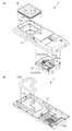
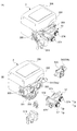
筐体6は、圧力タンク2、流路制御バルブユニット3、塩水供給ユニット4、及び配管ユニット5を収容する。筐体6は、圧力タンク2及び塩水供給ユニット4を支持する基台61と、圧力タンク2、流路制御バルブユニット3、塩水供給ユニット4、及び配管ユニット5の側方を取り囲む第1側板62及び第2側板63と、圧力タンク2、流路制御バルブユニット3、塩水供給ユニット4、及び配管ユニット5の上方を覆う外蓋部材64と、を備える。筐体6は、全体視で直方体状である。なお、筐体6が直方体状ではなく、筐体6の側板の外面は、丸みを帯びていてもよい。
流路制御バルブユニット3は、圧力タンク2に取り付けられて、圧力タンク2によって支持される。配管ユニット5は、流路制御バルブユニット3に取り付けられて、流路制御バルブユニット3によって支持される。
The housing 6 accommodates the pressure tank 2, the flow path control valve unit 3, the salt water supply unit 4, and the piping unit 5. The housing 6 includes a base 61 that supports the pressure tank 2 and the salt water supply unit 4, and a first side plate 62 that surrounds the side of the pressure tank 2, the flow path control valve unit 3, the salt water supply unit 4, and the piping unit 5. And a second side plate 63, a pressure tank 2, a flow path control valve unit 3, a salt water supply unit 4, and an outer lid member 64 that covers the piping unit 5. The housing 6 has a rectangular parallelepiped shape as a whole. In addition, the housing | casing 6 is not a rectangular parallelepiped shape, The outer surface of the side plate of the housing | casing 6 may be rounded.
The flow path control valve unit 3 is attached to the pressure tank 2 and supported by the pressure tank 2. The piping unit 5 is attached to the flow path control valve unit 3 and supported by the flow path control valve unit 3.

図2、図3に示すように、基台61は、平面視で矩形の形状を有する。基台61は、平面視で両長辺及び両短辺の全周面にアンカー取付部613を備える。基台61は、樹脂材料からなる。アンカー取付部613は、基台61と同じ樹脂材料からなり、基台61と一体成形される。アンカー取付部613には、アンカー金具614が取り付けられる。例えば、アンカーボルト(図示せず)を用いてアンカー金具614を固定することによって、硬水軟化装置1は、設置場所に強固に設置される。なお、全てのアンカー取付部613を用いる必要は無く、設置場所や必要な設置強度などに応じて、一部のアンカー取付部613のみ用いてもよい。   As shown in FIGS. 2 and 3, the base 61 has a rectangular shape in plan view. The base 61 includes anchor attachment portions 613 on the entire peripheral surfaces of both long sides and both short sides in plan view. The base 61 is made of a resin material. The anchor attachment portion 613 is made of the same resin material as the base 61 and is integrally formed with the base 61. An anchor fitting 614 is attached to the anchor attachment portion 613. For example, by fixing the anchor fitting 614 using an anchor bolt (not shown), the water softening device 1 is firmly installed at the installation location. Note that it is not necessary to use all the anchor attachment portions 613, and only some of the anchor attachment portions 613 may be used according to the installation location, the required installation strength, and the like.

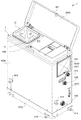
図2に示すように、第1側板62及び第2側板63は、下縁部で基台61に固定される。第1側板62は、硬水軟化装置1の背面及び左右両側面を覆い、第2側板63は、硬水軟化装置1の前面を覆う。第1側板62の右側面には、配管ユニット5の原水導入部510及び軟水導出部520、排水継手550が設けられる。図10に示すように、第1側板62の右側面の上部には、操作具配置部としての操作具ボックス621が設けられる。操作具ボックス621の内部には、第1のバイパス切替弁515を切り替える際に手動で操作される第1のバイパス切替弁操作具5151と、第2のバイパス切替弁531を切り替える際に手動で操作される第2のバイパス切替弁操作具5311と、原水ストレーナ511を洗浄する際に手動で操作される原水ストレーナ操作具としての原水ストレーナ蓋5111と、処理水ストレーナ522を洗浄する際に手動で操作される処理水ストレーナ操作具としての検水コック5221と、が集合して配置(格納)される。
検水コック5221は、ストレーナ排出管5222(ストレーナ排出ラインL62)に設けられる。なお、操作具の形態は制限されず、ハンドル、レバー、ツマミ(摘み)、ノブが例示される。
As shown in FIG. 2, the first side plate 62 and the second side plate 63 are fixed to the base 61 at the lower edge portion. The first side plate 62 covers the back surface and the left and right side surfaces of the water softening device 1, and the second side plate 63 covers the front surface of the water softening device 1. On the right side surface of the first side plate 62, a raw water introduction portion 510, a soft water lead-out portion 520, and a drainage joint 550 of the piping unit 5 are provided. As shown in FIG. 10, an operation tool box 621 serving as an operation tool placement unit is provided on the upper portion of the right side surface of the first side plate 62. Inside the operation tool box 621, the first bypass switching valve operating tool 5151 that is manually operated when switching the first bypass switching valve 515 and the manual operation when switching the second bypass switching valve 531 are performed. Second bypass switching valve operating tool 5311, a raw water strainer lid 5111 as a raw water strainer operating tool that is manually operated when cleaning the raw water strainer 511, and a manual operation when cleaning the treated water strainer 522. The test water cock 5221 as the treated water strainer operating tool is arranged and stored (stored).
The water inspection cock 5221 is provided in the strainer discharge pipe 5222 (strainer discharge line L62). The form of the operation tool is not limited, and examples thereof include a handle, a lever, a knob (a knob), and a knob.

操作具ボックス621の右下手前には、水抜き口6211が設けられる。水抜き口6211は、例えば検水コック5221のストレーナ排出管5222から漏れる漏水を、操作具ボックス621の内部から排出するためのものである。操作具ボックス621は、操作具ボックス621を覆って蓋をする蓋板部材622を備える。蓋板部材622の右下には、水抜き口6211の上方を覆うように手前に膨出した膨出部6221が設けられる。蓋板部材622は、その上縁部を操作具ボックス621の係止部に下から差し込んだ状態で、下縁部の中央孔に挿通した化粧ネジ6222を操作具ボックス621のボス穴6212にネジ留めすることにより、操作具ボックス621に取り付けられる。蓋板部材622は、操作具ボックス621に取り付けられたときに、第1側板62の右側面と略面一になる。図3、図9に示すように、配管ユニット5の組立体は、筐体6に対して操作具ボックス621が設けられた面の近傍に配置される。   A drain port 6211 is provided in front of the operation tool box 621 on the lower right side. The drain port 6211 is for discharging, for example, water leaking from the strainer discharge pipe 5222 of the water inspection cock 5221 from the inside of the operation tool box 621. The operation tool box 621 includes a cover plate member 622 that covers and covers the operation tool box 621. A bulging portion 6221 bulging forward is provided at the lower right of the cover plate member 622 so as to cover the upper side of the drain port 6211. The cover plate member 622 is screwed into the boss hole 6212 of the operation tool box 621 with a decorative screw 6222 inserted through the center hole of the lower edge portion with the upper edge portion inserted into the locking portion of the operation tool box 621 from below. By fastening, it is attached to the operation tool box 621. The lid plate member 622 is substantially flush with the right side surface of the first side plate 62 when attached to the operation tool box 621. As shown in FIGS. 3 and 9, the assembly of the piping unit 5 is arranged in the vicinity of the surface of the housing 6 on which the operation tool box 621 is provided.

第1側板62及び第2側板63の上縁部には、中間パネル7が載置される。中間パネル7は、中間パネル部材71と、内蓋部材72と、制御ボックス73とを備える。中間パネル部材71は、第1側板62の両側面の上縁部に固定される。外蓋部材64は、背面側に枢支軸を設けて中間パネル部材71に対して開閉自在に取り付けられる。外蓋部材64の前面側の中央には、シリンダ錠641が固定される。中間パネル部材71の前面側の中央には、シリンダ錠641を受け入れて保持するための保持部642が固定される。外蓋部材64を閉じてシリンダ錠641をロックしておくことにより、無断で外蓋部材64が開けられて予期せぬ事故が起こりかねない事態を未然に防止することができる。   The intermediate panel 7 is placed on the upper edges of the first side plate 62 and the second side plate 63. The intermediate panel 7 includes an intermediate panel member 71, an inner lid member 72, and a control box 73. The intermediate panel member 71 is fixed to the upper edge portions of both side surfaces of the first side plate 62. The outer lid member 64 is attached to the intermediate panel member 71 so as to be openable and closable by providing a pivot shaft on the back side. A cylinder lock 641 is fixed at the center of the front side of the outer lid member 64. A holding portion 642 for receiving and holding the cylinder lock 641 is fixed at the center of the front side of the intermediate panel member 71. By closing the outer lid member 64 and locking the cylinder lock 641, it is possible to prevent a situation in which the outer lid member 64 is opened without permission and an unexpected accident may occur.

図2、図3、図8に示すように、中間パネル部材71は、外蓋部材64の下方において、圧力タンク2、流路制御バルブユニット3、塩水供給ユニット4、及び配管ユニット5の上方を覆って配置される。中間パネル部材71は、塩水タンク41の上方位置に原料投入口711、712を備える。具体的には、第1原料投入口711は、中間パネル部材71の上面から上向きに突出するフランジで囲まれた領域である。第2原料投入口712は、第1原料投入口711の僅かに下方において、中間パネル部材71の下面から下向きに突出するフランジで囲まれた領域である。第2原料投入口712は、塩水タンク41の原料導入口41A4と相似形で僅かに小さい形状である。第1原料投入口711及び第2原料投入口712は、上下方向に互いに連通する。   As shown in FIGS. 2, 3, and 8, the intermediate panel member 71 is located above the pressure tank 2, the flow path control valve unit 3, the salt water supply unit 4, and the piping unit 5 below the outer lid member 64. It is placed over. The intermediate panel member 71 includes raw material inlets 711 and 712 at a position above the salt water tank 41. Specifically, the first raw material inlet 711 is a region surrounded by a flange that protrudes upward from the upper surface of the intermediate panel member 71. The second raw material inlet 712 is an area surrounded by a flange that protrudes downward from the lower surface of the intermediate panel member 71 slightly below the first raw material inlet 711. The second raw material inlet 712 is similar to the raw material inlet 41A4 of the salt water tank 41 and has a slightly smaller shape. The first raw material input port 711 and the second raw material input port 712 communicate with each other in the vertical direction.

下向きフランジ状の第2原料投入口712の外周には、パッキン部材7121が装着される。パッキン部材7121の内周は、第2原料投入口712の下向きフランジの外周全体に密着する形状及び大きさを有する。パッキン部材7121の外周は、塩水タンク41の原料導入口41A4の内周全体に密着する形状及び大きさを有する。そのため、中間パネル部材71のパッキン部材7121が装着された第2原料投入口712を塩水タンク41の原料導入口41A4に対して上方から押し込むと、原料導入口41A4の内側に第2原料投入口712が一体に接続される。第1原料投入口711の上向きフランジに内蓋部材72を被せることによって、第1原料投入口711は閉鎖され、従って、第2原料投入口712も閉鎖される。   A packing member 7121 is attached to the outer periphery of the second raw material charging port 712 having a downward flange shape. The inner periphery of the packing member 7121 has a shape and a size that are in close contact with the entire outer periphery of the downward flange of the second raw material inlet 712. The outer periphery of the packing member 7121 has a shape and a size that are in close contact with the entire inner periphery of the raw material introduction port 41A4 of the salt water tank 41. Therefore, when the second raw material inlet 712 to which the packing member 7121 of the intermediate panel member 71 is attached is pushed into the raw material inlet 41A4 of the salt water tank 41 from above, the second raw material inlet 712 is placed inside the raw material inlet 41A4. Are connected together. By covering the upward flange of the first raw material charging port 711 with the inner lid member 72, the first raw material charging port 711 is closed, and thus the second raw material charging port 712 is also closed.

中間パネル部材71は、硬性樹脂材料からなり、具体的には、アクリロニトリルスチレンアクリレート(略称:ASA)からなる。内蓋部材72は、軟性樹脂材料からなり、具体的には、低密度ポリエチレン(略称:LDPE)からなる。中間パネル部材71及び内蓋部材72は、シール性を向上させるための別部材及び/又はコーティングを備えていない。尚、上部タンク41Aは、ポリプロピレン(略称:PP)からなる。   The intermediate panel member 71 is made of a hard resin material, specifically, acrylonitrile styrene acrylate (abbreviation: ASA). The inner lid member 72 is made of a soft resin material, specifically, low-density polyethylene (abbreviation: LDPE). The intermediate panel member 71 and the inner lid member 72 do not include another member and / or a coating for improving the sealing performance. The upper tank 41A is made of polypropylene (abbreviation: PP).

制御ボックス73は、塩水タンク41の上方から外れた位置において、中間パネル部材71の下側に固定される。制御ボックス73には、硬水軟化装置1の制御に用いる電子機器731が格納される。電子機器731は、商用交流電力を直流電力に変換するスイッチング電源7311と、スイッチング電源7311で変換された直流電力で駆動され、流路制御バルブユニット3の動作を制御するためのマイコン7312とを備える。マイコン7312の駆動電圧は、5〜24Vの範囲である。マイコン7312は、少なくともCPU(図示せず)、メモリ(図示せず)、表示機器7313及び操作ボタン7314が実装されたワンボードマイコンとして構成される。中間パネル部材71には、制御ボックス73の固定状態において表示機器7313及び操作ボタン7314の位置に対応するように、表示機器7313を視認可能で、且つ操作ボタン7314を押下可能な表示操作領域732が設けられる。   The control box 73 is fixed to the lower side of the intermediate panel member 71 at a position removed from above the salt water tank 41. The control box 73 stores an electronic device 731 used for controlling the water softening device 1. The electronic device 731 includes a switching power supply 7311 that converts commercial AC power into DC power, and a microcomputer 7312 that is driven by the DC power converted by the switching power supply 7311 and controls the operation of the flow path control valve unit 3. . The drive voltage of the microcomputer 7312 is in the range of 5 to 24V. The microcomputer 7312 is configured as a one-board microcomputer on which at least a CPU (not shown), a memory (not shown), a display device 7313, and operation buttons 7314 are mounted. The intermediate panel member 71 has a display operation area 732 in which the display device 7313 can be visually recognized and the operation button 7314 can be pressed so as to correspond to the positions of the display device 7313 and the operation button 7314 when the control box 73 is fixed. Provided.

[硬水軟化装置1の運転動作]
次に、本実施形態における硬水軟化装置1の運転動作について説明する。硬水軟化装置1は、運転モードとして水処理モードと、再生モードと、洗浄モードと、補水モードと、待機モードと、を有する。
[Operation of water softening device 1]
Next, the operation | movement operation | movement of the water softening apparatus 1 in this embodiment is demonstrated. The water softening device 1 has a water treatment mode, a regeneration mode, a cleaning mode, a water replenishment mode, and a standby mode as operation modes.

水処理モードは、圧力タンク2に原水W1を導入することにより処理水(軟水W2)を製造するモードである。水処理モードにおいて、マイコン7312は、水処理工程を実行する。   The water treatment mode is a mode for producing treated water (soft water W2) by introducing the raw water W1 into the pressure tank 2. In the water treatment mode, the microcomputer 7312 executes a water treatment process.

再生モードは、圧力タンク2に再生液としての塩水W3を導入することによりイオン交換樹脂床211を再生するモードである。再生モードにおいて、マイコン7312は、再生工程、押出工程及びエア抜き工程を順に実行する。   The regeneration mode is a mode in which the ion exchange resin bed 211 is regenerated by introducing salt water W3 as a regeneration solution into the pressure tank 2. In the regeneration mode, the microcomputer 7312 sequentially performs a regeneration process, an extrusion process, and an air bleeding process.

洗浄モードは、圧力タンク2に洗浄液としての原水W1を導入することにより、圧力タンク2内に上昇流を生成し、イオン交換樹脂床211を洗浄するモードである。水処理モードにおいて、マイコン7312は、洗浄工程を実行する。   The cleaning mode is a mode for cleaning the ion exchange resin bed 211 by generating an upward flow in the pressure tank 2 by introducing raw water W1 as a cleaning liquid into the pressure tank 2. In the water treatment mode, the microcomputer 7312 executes a cleaning process.

補水モードは、原水W1を塩水タンク4へ補給するモードである。補水モードにおいて、マイコン7312は、補水工程を実行する。
待機モードは、圧力タンク2内における液体の制御を行わない(圧力タンク2に流体を導入しない)モードである。待機モードにおいて、マイコン7312は、待機工程を実行する。
The water replenishment mode is a mode in which the raw water W1 is replenished to the salt water tank 4. In the water replenishment mode, the microcomputer 7312 executes a water replenishment process.
The standby mode is a mode in which the liquid in the pressure tank 2 is not controlled (fluid is not introduced into the pressure tank 2). In the standby mode, the microcomputer 7312 executes a standby process.

マイコン7312は、所定の移行条件(イベント)に基づいて、各運転モードを切り換えるように流路制御バルブユニット3を制御する。各運転モードの切換えの詳細については、本願と同一出願人による特願2016−018129における図10及びこれに関連する説明を援用することにより、本明細書での詳細な説明を省略する。   The microcomputer 7312 controls the flow path control valve unit 3 so as to switch each operation mode based on a predetermined transition condition (event). The details of the switching of each operation mode will be omitted by using FIG. 10 and the description related thereto in Japanese Patent Application No. 2006-018129 by the same applicant as the present application.

以下、上述した運転モードで実行される工程を説明する。流路制御バルブユニット3は、マイコン7312からの指示に従ってメインバルブ31の状態並びにブラインバルブ35及びドレンバルブ36の開閉状態を切り換え、運転モード毎に規定された工程を実行する。まず、水処理工程について説明し、他の工程については、水処理工程との相違点のみ説明する。
なお、以下の各工程において、ユーザーやメンテナンス員が操作しない限り、第1のバイパス切替弁515は開位置にあり、第2のバイパス切替弁531は閉位置にあり、検水コック5221は閉位置にある。
Hereafter, the process performed in the operation mode mentioned above is demonstrated. The flow path control valve unit 3 switches the state of the main valve 31 and the open / close state of the brine valve 35 and the drain valve 36 in accordance with an instruction from the microcomputer 7312 and executes a process defined for each operation mode. First, a water treatment process is demonstrated and about a different process, only a difference with a water treatment process is demonstrated.
In each of the following steps, the first bypass switching valve 515 is in the open position, the second bypass switching valve 531 is in the closed position, and the water inspection cock 5221 is in the closed position unless operated by a user or maintenance personnel. It is in.

[水処理工程]
図1に示すように、水処理工程では、流路制御バルブユニット3において、メインバルブ31は第1の状態にあり、ブラインバルブ35及びドレンバルブ36はいずれも閉位置にある。そのため、原水導入部510から硬水軟化装置1に導入される原水W1は、原水ラインL11、原水ラインL12、流路制御バルブ31の第1孔3111及び孔3124を順次流れて、圧力タンク2の集配液管231に供給され、底部スクリーン242から配水される。底部スクリーン242から配水された原水W1は、イオン交換樹脂床211を上昇流で通過する。原水W1が圧力タンク2の内部を上昇流で通過する過程において、原水W1の硬度成分は、ナトリウムイオン(又は、カリウムイオン)へ置換され、原水W1は軟水化される。イオン交換樹脂床211を通過した処理水(軟水W2)は、圧力タンク2の頂部で頂部スクリーン241へ集水される。その後、軟水W2は、軟水ラインL21、軟水ラインL22、流路制御バルブ31の第3孔3113及び第2孔3112、軟水ラインL23、軟水ラインL24、軟水ラインL25を順次流れて、軟水導出部520から硬水軟化装置1の外部へ導出されて、軟水W2の需要箇所へ供給される。
[Water treatment process]
As shown in FIG. 1, in the water treatment process, in the flow path control valve unit 3, the main valve 31 is in the first state, and both the brine valve 35 and the drain valve 36 are in the closed position. Therefore, the raw water W1 introduced into the hard water softening device 1 from the raw water introduction unit 510 sequentially flows through the raw water line L11, the raw water line L12, the first hole 3111 and the hole 3124 of the flow path control valve 31, and the collection and distribution of the pressure tank 2 The liquid is supplied to the liquid pipe 231 and distributed from the bottom screen 242. The raw water W1 distributed from the bottom screen 242 passes through the ion exchange resin bed 211 in an upward flow. In the process in which the raw water W1 passes through the inside of the pressure tank 2 in an upward flow, the hardness component of the raw water W1 is replaced with sodium ions (or potassium ions), and the raw water W1 is softened. The treated water (soft water W <b> 2) that has passed through the ion exchange resin bed 211 is collected on the top screen 241 at the top of the pressure tank 2. Thereafter, the soft water W2 sequentially flows through the soft water line L21, the soft water line L22, the third hole 3113 and the second hole 3112 of the flow path control valve 31, the soft water line L23, the soft water line L24, and the soft water line L25, and the soft water deriving unit 520 To the outside of the hard water softening device 1 and supplied to the demand point of the soft water W2.

[再生工程]
再生工程では、流路制御バルブユニット3において、メインバルブ31は第2の状態にあり、ブラインバルブ35及びドレンバルブ36はいずれも開位置にある。再生工程の詳細については、本願と同一出願人による特願2016−018129における第1実施形態に係る再生プロセスに関する説明を援用することにより、本明細書での詳細な説明を省略する。
[Regeneration process]
In the regeneration process, in the flow path control valve unit 3, the main valve 31 is in the second state, and the brine valve 35 and the drain valve 36 are both in the open position. About the detail of a reproduction | regeneration process, detailed description in this specification is abbreviate | omitted by using description regarding the reproduction | regeneration process which concerns on 1st Embodiment in Japanese Patent Application No. 2006-018129 by the same applicant as this application.

[押出工程]
押出工程では、流路制御バルブユニット3において、メインバルブ31は第2の状態にあり、ブラインバルブ35は閉位置にあり、ドレンバルブ36は開位置にある。押出工程の詳細については、本願と同一出願人による特願2016−018129における第1実施形態に係る押出プロセスに関する説明を援用することにより、本明細書での詳細な説明を省略する。
[Extrusion process]
In the extrusion process, in the flow path control valve unit 3, the main valve 31 is in the second state, the brine valve 35 is in the closed position, and the drain valve 36 is in the open position. About the detail of an extrusion process, detailed description in this specification is abbreviate | omitted by using the description regarding the extrusion process which concerns on 1st Embodiment in Japanese Patent Application No. 2006-018129 by the same applicant as this application.

[エア抜き工程]
エア抜き工程では、流路制御バルブユニット3において、メインバルブ31は第3の状態にあり、ブラインバルブ35は閉位置にあり、ドレンバルブ36は開位置にある。エア抜き工程の詳細については、本願と同一出願人による特願2016−018129における第1実施形態に係る上昇プロセスに関する説明を援用することにより、本明細書での詳細な説明を省略する。
[Air bleeding process]
In the air venting process, in the flow path control valve unit 3, the main valve 31 is in the third state, the brine valve 35 is in the closed position, and the drain valve 36 is in the open position. About the detail of an air bleeding process, detailed description in this specification is abbreviate | omitted by using description regarding the raising process which concerns on 1st Embodiment in Japanese Patent Application No. 2006-018129 by the same applicant as this application.

[洗浄工程]
洗浄工程では、流路制御バルブユニット3において、メインバルブ31は第4の状態にあり、ブラインバルブ35は閉位置にあり、ドレンバルブ36は開位置にある。洗浄工程の詳細については、本願と同一出願人による特願2016−018129における第1実施形態に係る下降プロセスに関する説明を援用することにより、本明細書での詳細な説明を省略する。
[Washing process]
In the cleaning process, in the flow path control valve unit 3, the main valve 31 is in the fourth state, the brine valve 35 is in the closed position, and the drain valve 36 is in the open position. About the detail of a washing | cleaning process, detailed description in this specification is abbreviate | omitted by using description regarding the descending process which concerns on 1st Embodiment in Japanese Patent Application No. 2006-018129 by the same applicant as this application.

[補水工程]
補水工程では、流路制御バルブユニット3において、メインバルブ31は第1の状態にあり、ブラインバルブ35は開位置にあり、ドレンバルブ36は閉位置にある。補水工程の詳細については、本願と同一出願人による特願2016−018129における第1実施形態に係る補水プロセスに関する説明を援用することにより、本明細書での詳細な説明を省略する。
[Water replenishment process]
In the water replenishment process, in the flow path control valve unit 3, the main valve 31 is in the first state, the brine valve 35 is in the open position, and the drain valve 36 is in the closed position. About the detail of a water replenishment process, the detailed description in this specification is abbreviate | omitted by using the description regarding the water replenishment process which concerns on 1st Embodiment in Japanese Patent Application No. 2006-018129 by the same applicant as this application.

[待機工程]
待機工程では、流路制御バルブユニット3において、メインバルブ31は第2の状態にあり、ブラインバルブ35及びドレンバルブ36はいずれも閉位置にある。待機工程の詳細については、本願と同一出願人による特願2016−018129における第1実施形態に係る待機プロセスに関する説明を援用することにより、本明細書での詳細な説明を省略する。
[Standby process]
In the standby process, in the flow path control valve unit 3, the main valve 31 is in the second state, and both the brine valve 35 and the drain valve 36 are in the closed position. About the detail of a standby process, detailed description in this specification is abbreviate | omitted by using description regarding the standby process which concerns on 1st Embodiment in Japanese Patent Application No. 2006-018129 by the same applicant as this application.

[手動バイパスの操作]
硬水軟化装置1の給水を手動によりバイパスさせる場合、ユーザーやメンテナンス員は、次のように操作する。すなわち、硬水軟化装置1が水処理モード(流路制御バルブユニット3が水処理工程の状態)の実行中において、操作具ボックス621を開いて第1のバイパス切替弁515を閉位置とし、第2のバイパス切替弁531を開位置とする。
[Manual bypass operation]
When bypassing the water supply of the water softening apparatus 1 manually, a user and a maintenance worker operate as follows. That is, when the water softening device 1 is in the water treatment mode (the flow path control valve unit 3 is in the water treatment step), the operation tool box 621 is opened to place the first bypass switching valve 515 in the closed position, and the second The bypass switching valve 531 is set to the open position.

この操作により、原水導入部510から硬水軟化装置1に導入される原水W1は、原水ラインL11の原水ストレーナ511、真空逃し弁512、逆止め弁514を順次流れ、続いて、バイパスラインL61の第2のバイパス切替弁531、逆止め弁532を順次流れ、続いて、軟水ラインL25の切替弁523の下流側を順次流れて、軟水W2の需要箇所へ供給される。   By this operation, the raw water W1 introduced into the hard water softening device 1 from the raw water introduction unit 510 sequentially flows through the raw water strainer 511, the vacuum relief valve 512, and the check valve 514 of the raw water line L11, and then the first of the bypass line L61. 2 sequentially flows through the bypass switching valve 531 and the check valve 532, and then sequentially flows downstream of the switching valve 523 of the soft water line L25 to be supplied to the demand point of the soft water W2.

[軟水ストレーナ洗浄の操作]
軟水ストレーナ522の洗浄を行う場合、ユーザーやメンテナンス員は、次のように操作する。すなわち、硬水軟化装置1が水処理モード(流路制御バルブユニット3が水処理工程の状態)の実行中において、操作具ボックス621を開いて第1のバイパス切替弁515を閉位置とし、第2のバイパス切替弁531を開位置とする。そして、検水コック5221を開位置とする。
[Operation of soft water strainer cleaning]
When cleaning the soft water strainer 522, a user or a maintenance staff operates as follows. That is, when the water softening device 1 is in the water treatment mode (the flow path control valve unit 3 is in the water treatment step), the operation tool box 621 is opened to place the first bypass switching valve 515 in the closed position, and the second The bypass switching valve 531 is set to the open position. Then, the water inspection cock 5221 is set to the open position.

この操作により、原水導入部510から硬水軟化装置1に導入される原水W1は、原水ラインL11の原水ストレーナ511、真空逃し弁512、逆止め弁514を順次流れ、続いて、バイパスラインL61の第2のバイパス切替弁531、逆止め弁532を順次流れ、続いて、軟水ラインL25の切替弁523、軟水ストレーナ522を順次流れ、最後に検水コック5221及びストレーナ排出管5222(ストレーナ排出ラインL62)を通って排出される。このとき、先行して軟水ストレーナ522が捕捉していた軟水W2に混入した異物(イオン交換樹脂の細粒や破砕片)は、検水コック5221を開けることにより、ストレーナ排出管5222(ストレーナ排出ラインL62)を通って系外に排出される。   By this operation, the raw water W1 introduced into the hard water softening device 1 from the raw water introduction unit 510 sequentially flows through the raw water strainer 511, the vacuum relief valve 512, and the check valve 514 of the raw water line L11, and then the first of the bypass line L61. 2 sequentially flows through the bypass switching valve 531 and the check valve 532, and then sequentially flows through the switching valve 523 and the soft water strainer 522 of the soft water line L25, and finally the test water cock 5221 and the strainer discharge pipe 5222 (strainer discharge line L62). Discharged through. At this time, foreign matter (fine particles or crushed pieces of ion exchange resin) mixed in the soft water W2 previously captured by the soft water strainer 522 opens the test water cock 5221, thereby causing the strainer discharge pipe 5222 (strainer discharge line). L62) is discharged out of the system.

上記実施形態では、操作具ボックス621を第1側板62の右側面の上部に設けたが、本発明は、これに限定されない。例えば、第1側板62の左側面若しくは背面又は第2側板63の前面のいずれかに、操作具ボックス621を設けてもよい。   In the above embodiment, the operation tool box 621 is provided on the upper portion of the right side surface of the first side plate 62, but the present invention is not limited to this. For example, the operation tool box 621 may be provided on either the left side surface or the back surface of the first side plate 62 or the front surface of the second side plate 63.

また、上記実施形態では、原水導入部510、軟水導出部520及び排水継手550を第1側板62の右側面に設けたが、本発明は、これに限定されない。例えば、第1側板62の左側面若しくは背面又は第2側板63の前面のいずれかに、排水継手550を設けてもよい。   Moreover, in the said embodiment, although the raw | natural water introducing | transducing part 510, the soft water derivation | leading-out part 520, and the drainage coupling 550 were provided in the right side surface of the 1st side plate 62, this invention is not limited to this. For example, the drainage joint 550 may be provided on either the left side surface or the back surface of the first side plate 62 or the front surface of the second side plate 63.

また、塩水バルブ組立体45は、塩水(再生液)が所定の塩水濃度に達しているか否かを検出するためのフロートスイッチ(図示せず)を備えてもよい。   Further, the salt water valve assembly 45 may include a float switch (not shown) for detecting whether or not the salt water (regeneration liquid) has reached a predetermined salt water concentration.

上述した本実施形態の硬水軟化装置1によれば、例えば、以下のような様々な効果が奏される。
本実施形態の硬水軟化装置1は、原水W1を導入することにより軟水W2を製造するイオン交換樹脂床211が収容される圧力タンク2と、イオン交換樹脂床211に対して塩水W3を供給する塩水供給ユニット4と、原水導入部510及び軟水導出部520を有する配管ユニット5と、圧力タンク2、塩水供給ユニット4及び配管ユニット5と接続され、流路を切り換える流路制御バルブユニット3と、圧力タンク2、塩水供給ユニット4、配管ユニット5及び流路制御バルブユニット3を収容する筐体6と、を備える。筐体6は、前後左右面のいずれかに操作具配置部621が設けられ、配管ユニット5は、(a)原水導入部510と流路制御バルブユニット3の原水流入ポート302とを連絡する原水配管51と、(b)流路制御バルブユニット3の軟水流出ポート303と軟水導出部520とを連絡する軟水配管52と、(c)原水配管510と軟水配管520とを接続するバイパス配管53と、(d)原水W1をバイパス配管53に流入させずに流路制御バルブユニット3に流入させる非バイパス経路、又は原水W1を流路制御バルブユニット3に流入させずにバイパス配管53に流入させるバイパス経路に切替可能なバイパス切替弁515、531と、(e)原水配管51に設けられた原水ストレーナ511と、(f)軟水配管52に設けられた軟水ストレーナ522と、(g)バイパス切替弁515、531を切り替える際に手動で操作されるバイパス切替弁操作具5151、5311と、(h)原水ストレーナ511を洗浄する際に手動で操作される原水ストレーナ操作具5111と、(i)軟水ストレーナ522を洗浄する際に手動で操作される軟水ストレーナ操作具5221と、を含む組立体である。配管ユニット5の組立体は、筐体6に対して操作具配置部621が設けられた面の近傍に配置され、バイパス切替弁操作具5151、5311、原水ストレーナ操作具5111及び軟水ストレーナ操作具5221は、操作具配置部621に集合して配置されている。
According to the water softening apparatus 1 of this embodiment mentioned above, the following various effects are show | played, for example.
The water softening device 1 of the present embodiment includes a pressure tank 2 in which an ion exchange resin bed 211 that produces soft water W2 is introduced by introducing raw water W1, and salt water that supplies salt water W3 to the ion exchange resin bed 211. A flow path control valve unit 3 that is connected to the supply unit 4, the pipe unit 5 having the raw water introduction part 510 and the soft water lead-out part 520, the pressure tank 2, the salt water supply unit 4 and the pipe unit 5, and switches the flow path; A tank 2, a salt water supply unit 4, a piping unit 5, and a housing 6 that houses the flow path control valve unit 3. The casing 6 is provided with an operation tool arrangement portion 621 on either the front, back, left, or right side, and the piping unit 5 is connected to (a) the raw water introduction port 510 and the raw water inflow port 302 of the flow path control valve unit 3. A pipe 51, (b) a soft water pipe 52 connecting the soft water outflow port 303 of the flow path control valve unit 3 and the soft water outlet 520, and (c) a bypass pipe 53 connecting the raw water pipe 510 and the soft water pipe 520. (D) A non-bypass path for flowing the raw water W1 into the flow path control valve unit 3 without flowing into the bypass pipe 53, or a bypass for flowing the raw water W1 into the bypass pipe 53 without flowing into the flow path control valve unit 3 Bypass switching valves 515 and 531 that can be switched to a path, (e) raw water strainer 511 provided in the raw water pipe 51, and (f) soft water provided in the soft water pipe 52. A trainer 522; (g) bypass switch valve operating tools 5151 and 5311 that are manually operated when switching the bypass switch valves 515 and 531; and (h) a raw water strainer that is manually operated when cleaning the raw water strainer 511. The assembly includes an operation tool 5111 and (i) a soft water strainer operation tool 5221 that is manually operated when the soft water strainer 522 is cleaned. The assembly of the piping unit 5 is disposed in the vicinity of the surface of the housing 6 where the operation tool placement unit 621 is provided. Bypass switching valve operation tools 5151 and 5311, raw water strainer operation tool 5111, and soft water strainer operation tool 5221. Are arranged together in the operation tool arrangement part 621.

そのため、使用者や作業者がバイパス切替弁515、531を切り替える際や、原水ストレーナ511又は軟水ストレーナ522を洗浄する際に、操作具配置部621に配置されたバイパス切替弁操作具5151、5311、原水ストレーナ操作具5111又は軟水ストレーナ操作具5221を用いて必要な操作を行うことができる。そのため、各操作具にアクセスすることが容易であり、手動操作の利便性が向上する。   Therefore, when a user or an operator switches the bypass switching valves 515 and 531 or when the raw water strainer 511 or the soft water strainer 522 is washed, the bypass switching valve operation tools 5151 and 5311 disposed in the operation tool placement unit 621 are provided. Necessary operations can be performed using the raw water strainer operation tool 5111 or the soft water strainer operation tool 5221. Therefore, it is easy to access each operation tool, and the convenience of manual operation is improved.

また、操作具配置部621は、筐体6の前後左右面いずれかの上部に配置されている。詳細には、操作具配置部621は、筐体6の右側面の上部に配置されている。そのため、比較的背の低い硬水軟化装置1であっても、使用者や作業者があまり屈んだりせずに、必要な手動操作を行うことができる。   In addition, the operating tool placement unit 621 is placed on either the front, back, left, or right side of the housing 6. Specifically, the operation tool placement unit 621 is placed on the upper part of the right side surface of the housing 6. Therefore, even if it is the comparatively short water softening apparatus 1, a required manual operation can be performed, without a user and an operator bending much.

また、操作具配置部621は、バイパス切替弁操作具5151、5311、原水ストレーナ操作具5111及び軟水ストレーナ操作具5221を格納する操作具ボックス621として構成され、操作具ボックス621は、閉蓋時に筐体6の外面と略面一になる蓋板部材622を備える。そのため、蓋板部材622が操作具ボックス621を閉じている通常時には、操作具ボックス621目立ちにくく、外観性に優れる。   In addition, the operation tool placement unit 621 is configured as an operation tool box 621 for storing bypass switch valve operation tools 5151 and 5311, raw water strainer operation tool 5111, and soft water strainer operation tool 5221. The operation tool box 621 is enclosed when closed. A cover plate member 622 that is substantially flush with the outer surface of the body 6 is provided. Therefore, when the cover plate member 622 normally closes the operation tool box 621, the operation tool box 621 is hardly noticeable and has excellent appearance.

また、配管ユニット5は、(j)原水配管51の上流側から下流側に向かって順に設けられた真空逃し弁512、逆止め弁514、減圧弁516及び圧力逃し弁518からなる弁群を更に含み、原水配管51からのバイパス配管53の分岐部は、逆止め弁514と減圧弁516との間に配置される。そのため、バイパス切替弁515、531を流路制御バルブユニット3から離れた位置に配置することが容易であり、ひいてはバイパス切替弁操作具5151、5311を筐体6の右側面に配置させることが容易である。   The piping unit 5 further includes (j) a valve group including a vacuum relief valve 512, a check valve 514, a pressure reducing valve 516, and a pressure relief valve 518 provided in order from the upstream side to the downstream side of the raw water piping 51. A branch portion of the bypass pipe 53 including the raw water pipe 51 is disposed between the check valve 514 and the pressure reducing valve 516. Therefore, it is easy to dispose the bypass switching valves 515 and 531 at a position away from the flow path control valve unit 3, and as a result, it is easy to dispose the bypass switching valve operating tools 5151 and 5311 on the right side surface of the housing 6. It is.

以上、本発明の好ましい実施形態について説明した。しかし、本発明は、上述した実施形態に限定されることなく、種々の形態で実施することができる。   The preferred embodiments of the present invention have been described above. However, the present invention is not limited to the above-described embodiments, and can be implemented in various forms.

尚、上記実施形態では、操作具配置部621を、筐体6の右側面の上部に配置した。しかしながら、筐体6の左側面、前面又は背面のいずれかの上部に、操作具配置部621を配置してもよい。更に、筐体6の前後左右面のいずれかにおいて上部に限らない位置に、操作具配置部621を配置してもよい。   In the above embodiment, the operation tool placement unit 621 is placed on the upper right side of the housing 6. However, the operation tool placement portion 621 may be placed on the left side, front, or back of the housing 6. Furthermore, the operation tool placement unit 621 may be placed at a position not limited to the upper part on any of the front, rear, left, and right surfaces of the housing 6.

1 硬水軟化装置(イオン交換装置)
2 圧力タンク
211 イオン交換樹脂床
3 流路制御バルブユニット
302 原水流入ポート
303 軟水流出ポート(処理水流出ポート)
4 塩水供給ユニット(再生液供給ユニット)
5 配管ユニット
51 原水配管
510 原水導入部
511 原水ストレーナ
5111 原水ストレーナ蓋(原水ストレーナ操作具)
512 真空逃し弁
514 逆止め弁
515 第1のバイパス切替弁
5151 第1のバイパス切替弁操作具
516 減圧弁
518 圧力逃し弁
52 軟水配管(処理水配管)
520 軟水導出部(処理水導出部)
522 軟水ストレーナ(処理水ストレーナ)
5221 検水コック(処理水ストレーナ操作具)
53 バイパス配管
531 第2のバイパス切替弁
5311 第2のバイパス切替弁操作具
6 筐体
621 操作具ボックス(操作具配置部)
W1 原水
W2 軟水(処理水)
W3 塩水(再生液)
1 Water softener (ion exchanger)
2 Pressure tank 211 Ion exchange resin bed 3 Flow path control valve unit 302 Raw water inflow port 303 Soft water outflow port (treated water outflow port)
4 Salt water supply unit (regenerated liquid supply unit)
5 Piping unit 51 Raw water piping 510 Raw water introduction part 511 Raw water strainer 5111 Raw water strainer lid (raw water strainer operation tool)
512 Vacuum Relief Valve 514 Check Valve 515 First Bypass Switch Valve 5151 First Bypass Switch Valve Operating Tool 516 Pressure Reducing Valve 518 Pressure Relief Valve 52 Soft Water Pipe (Treatment Water Pipe)
520 Soft water outlet (treated water outlet)
522 Soft water strainer (treated water strainer)
5221 Water inspection cock (treated water strainer operation tool)
53 Bypass piping 531 2nd bypass switching valve 5311 2nd bypass switching valve operation tool 6 Case 621 Operation tool box (operation tool arrangement part)
W1 Raw water W2 Soft water (treated water)
W3 Brine (regenerated liquid)

Claims (4)

原水を導入することにより処理水を製造するイオン交換樹脂床が収容される圧力タンクと、
イオン交換樹脂床に対して再生液を供給する再生液供給ユニットと、
原水導入部及び処理水導出部を有する配管ユニットと、
前記圧力タンク、前記再生液供給ユニット及び前記配管ユニットと接続され、流路を切り換える流路制御バルブユニットと、
前記圧力タンク、前記再生液供給ユニット、前記配管ユニット及び前記流路制御バルブユニットを収容する筐体と、を備え、
前記筐体には、前後左右面のいずれかに操作具配置部が設けられ、
前記配管ユニットは、(a)前記原水導入部と前記流路制御バルブユニットの原水流入ポートとを連絡する原水配管と、(b)前記流路制御バルブユニットの処理水流出ポートと前記処理水導出部とを連絡する処理水配管と、(c)前記原水配管と前記処理水配管とを接続するバイパス配管と、(d)原水を前記バイパス配管に流入させずに前記流路制御バルブユニットに流入させる非バイパス経路、又は原水を前記流路制御バルブユニットに流入させずに前記バイパス配管に流入させるバイパス経路に切替可能なバイパス切替弁と、(e)前記原水配管に設けられた原水ストレーナと、(f)前記処理水配管に設けられた処理水ストレーナと、(g)前記バイパス切替弁を切り替える際に手動で操作されるバイパス切替弁操作具と、(h)前記原水ストレーナを洗浄する際に手動で操作される原水ストレーナ操作具と、(i)前記処理水ストレーナを洗浄する際に手動で操作される処理水ストレーナ操作具と、を含む組立体であり、
前記配管ユニットの組立体は、前記筐体に対して前記操作具配置部が設けられた面の近傍に配置され、
前記バイパス切替弁操作具、前記原水ストレーナ操作具及び前記処理水ストレーナ操作具は、前記操作具配置部に集合して配置されている、
イオン交換装置。
A pressure tank containing an ion exchange resin bed for producing treated water by introducing raw water;
A regenerative liquid supply unit for supplying the regenerative liquid to the ion exchange resin bed;
A piping unit having a raw water inlet and a treated water outlet;
A flow path control valve unit that is connected to the pressure tank, the regeneration liquid supply unit, and the piping unit, and switches the flow path;
A housing for housing the pressure tank, the regeneration liquid supply unit, the piping unit, and the flow path control valve unit;
The casing is provided with an operation tool arrangement portion on one of the front, rear, left and right sides,
The piping unit includes: (a) raw water piping that connects the raw water introduction unit and the raw water inflow port of the flow path control valve unit; and (b) a treated water outflow port of the flow path control valve unit and the treated water lead-out. A treated water pipe that communicates with the section; (c) a bypass pipe that connects the raw water pipe and the treated water pipe; and (d) a raw water that flows into the flow path control valve unit without flowing into the bypass pipe. A bypass switching valve that can be switched to a non-bypass path to be made, or a bypass path that allows raw water to flow into the bypass pipe without flowing into the flow path control valve unit, and (e) a raw water strainer provided in the raw water pipe, (F) a treated water strainer provided in the treated water pipe, (g) a bypass switching valve operating tool manually operated when switching the bypass switching valve, and (h) Serial raw water strainer raw water strainer operation member which is operated manually when cleaning the a assembly comprising a treated water strainer operation member which is operated manually when cleaning the (i) the treated water strainer,
The assembly of the piping unit is disposed in the vicinity of the surface on which the operation tool placement unit is provided with respect to the housing.
The bypass switching valve operation tool, the raw water strainer operation tool, and the treated water strainer operation tool are arranged together in the operation tool placement unit,
Ion exchange device.
前記操作具配置部は、前記筐体の前後左右面いずれかの上部に配置されている、
請求項1に記載のイオン交換装置。
The operation tool arrangement part is arranged on the upper part of either the front, rear, left, or right side of the housing.
The ion exchange apparatus according to claim 1.
前記操作具配置部は、前記バイパス切替弁操作具、前記原水ストレーナ操作具及び前記処理水ストレーナ操作具を格納する操作具ボックスとして構成され、
前記操作具ボックスは、閉蓋時に前記筐体の外面と略面一になる蓋板部材を備える、
請求項1又は2に記載のイオン交換装置。
The operation tool arrangement unit is configured as an operation tool box that stores the bypass switching valve operation tool, the raw water strainer operation tool, and the treated water strainer operation tool,
The operation tool box includes a cover plate member that is substantially flush with the outer surface of the housing when the lid is closed.
The ion exchange apparatus according to claim 1 or 2.
前記配管ユニットは、(j)前記原水配管の上流側から下流側に向かって順に設けられた真空逃し弁、逆止め弁、減圧弁及び圧力逃し弁からなる弁群を更に含み、
前記原水配管からの前記バイパス配管の分岐部は、前記逆止め弁と前記減圧弁との間に配置される、
請求項1〜3のいずれかに記載のイオン交換装置。
The piping unit further includes (j) a valve group including a vacuum relief valve, a check valve, a pressure reducing valve, and a pressure relief valve provided in order from the upstream side to the downstream side of the raw water piping,
A branch portion of the bypass pipe from the raw water pipe is disposed between the check valve and the pressure reducing valve.
The ion exchange apparatus in any one of Claims 1-3.
JP2016083623A 2016-04-19 2016-04-19 Ion exchange device Pending JP2017192889A (en)

Priority Applications (1)

Application Number Priority Date Filing Date Title
JP2016083623A JP2017192889A (en) 2016-04-19 2016-04-19 Ion exchange device

Applications Claiming Priority (1)

Application Number Priority Date Filing Date Title
JP2016083623A JP2017192889A (en) 2016-04-19 2016-04-19 Ion exchange device

Publications (1)

Publication Number Publication Date
JP2017192889A true JP2017192889A (en) 2017-10-26

Family

ID=60155777

Family Applications (1)

Application Number Title Priority Date Filing Date
JP2016083623A Pending JP2017192889A (en) 2016-04-19 2016-04-19 Ion exchange device

Country Status (1)

Country Link
JP (1) JP2017192889A (en)

Similar Documents

Publication Publication Date Title
JP6642231B2 (en) Regeneration liquid supply unit
JP6743468B2 (en) Regeneration liquid supply unit
JP6221865B2 (en) Ion exchanger
JP6701914B2 (en) Ion exchange device
JP6660017B2 (en) Regeneration liquid supply unit
JP5754164B2 (en) Ion exchanger
JP2017192889A (en) Ion exchange device
JP6701915B2 (en) Ion exchange device
CN210764688U (en) Water treatment machine
JP6672979B2 (en) Ion exchange equipment
JP6682981B2 (en) Regeneration liquid supply unit
JP6662171B2 (en) Ion exchange equipment
JP6672980B2 (en) Ion exchange equipment
CN210764693U (en) Water treatment machine
JP6688570B2 (en) Water softening device and method of regenerating water softening device
JP2003159590A (en) Water softener
KR101335813B1 (en) Sterilization apparatus and method of water purifier
JP2005261991A (en) Soft water feeder
JP6641110B2 (en) Water softener
JP6688571B2 (en) Water softener
JP2012166133A (en) Ion exchange device
CN214433683U (en) Water making component and water making equipment
JP2015174075A (en) Ion exchanger
JP2000254641A (en) Water softening device
JP6248719B2 (en) Ion exchanger

Legal Events

Date Code Title Description
A621 Written request for application examination

Free format text: JAPANESE INTERMEDIATE CODE: A621

Effective date: 20190122

A977 Report on retrieval

Free format text: JAPANESE INTERMEDIATE CODE: A971007

Effective date: 20191030

A131 Notification of reasons for refusal

Free format text: JAPANESE INTERMEDIATE CODE: A131

Effective date: 20191105

A521 Written amendment

Free format text: JAPANESE INTERMEDIATE CODE: A523

Effective date: 20191219

A02 Decision of refusal

Free format text: JAPANESE INTERMEDIATE CODE: A02

Effective date: 20200204