JP2017192568A - Supply pipe, absorption mat forming apparatus, and absorption mat forming method - Google Patents
Supply pipe, absorption mat forming apparatus, and absorption mat forming method Download PDFInfo
- Publication number
- JP2017192568A JP2017192568A JP2016084719A JP2016084719A JP2017192568A JP 2017192568 A JP2017192568 A JP 2017192568A JP 2016084719 A JP2016084719 A JP 2016084719A JP 2016084719 A JP2016084719 A JP 2016084719A JP 2017192568 A JP2017192568 A JP 2017192568A
- Authority
- JP
- Japan
- Prior art keywords
- superabsorbent resin
- supply
- supply port
- passage
- supply pipe
- Prior art date
- Legal status (The legal status is an assumption and is not a legal conclusion. Google has not performed a legal analysis and makes no representation as to the accuracy of the status listed.)
- Granted
Links
Images

Landscapes
- Absorbent Articles And Supports Therefor (AREA)
Abstract
Description
本件は、吸収マットを形成する装置および方法と、これらの装置および方法で用いられる高吸水性樹脂の供給管に関する。 The present invention relates to an apparatus and method for forming an absorbent mat and a superabsorbent resin supply pipe used in these apparatuses and methods.
従来、紙おむつや生理用ナプキンといった吸収性物品が知られている。吸収性物品には、着用者から排泄される尿や経血などの液体を吸収する吸収マットが設けられている。この吸収マットの一つとして、パルプやレーヨンなどの繊維材料に粉粒状の高吸水性樹脂が混合されたものが開発されている。繊維材料によって拡散された液体が高吸水性樹脂に保持されることで、吸収マットの吸液性を高めることができる。 Conventionally, absorbent articles such as paper diapers and sanitary napkins are known. The absorbent article is provided with an absorbent mat that absorbs liquid such as urine and menstrual blood excreted from the wearer. As one of the absorbent mats, a material in which a powdery superabsorbent resin is mixed with a fiber material such as pulp or rayon has been developed. Since the liquid diffused by the fiber material is held in the highly water-absorbent resin, the liquid absorption of the absorbent mat can be increased.
吸収マットでは、高吸水性樹脂の混合状態を調整することにより、吸液特性を向上させることができる。そこで、吸収マットにおいて高吸水性樹脂を所定の状態に混合する技術が提案されている。
たとえば、ラップシートで被包される吸収マットに混合される高吸水性樹脂を分級する技術が検討されている。この技術では、ラップシートの細孔径よりも大きい粒径と小さい粒径とに高吸水性樹脂が分級されたうえで、大きい粒径の高吸水性樹脂のみが散布されたラップシートに対して、パルプに混合された小さい粒径の高吸水性樹脂が積層される。このようにして得られた吸収マットによれば、ラップシートの目詰まりが抑えられ、液透過性が高められるとされる(特許文献1参照)。
In the absorbent mat, the liquid absorption characteristics can be improved by adjusting the mixing state of the superabsorbent resin. Therefore, a technique for mixing a highly water-absorbent resin in a predetermined state in an absorbent mat has been proposed.
For example, a technique for classifying a superabsorbent resin mixed in an absorbent mat encapsulated with a wrap sheet has been studied. In this technique, after the superabsorbent resin is classified into a particle size larger and smaller than the pore size of the wrap sheet, the wrap sheet in which only the superabsorbent resin having a large particle size is sprayed, A superabsorbent resin having a small particle size mixed with pulp is laminated. According to the absorbent mat thus obtained, clogging of the wrap sheet is suppressed and the liquid permeability is improved (see Patent Document 1).
しかしながら、吸収マットにおいて高吸水性樹脂のみが散布された層では、パルプが含まれないことから、液体の拡散性が低下するおそれがある。そのうえ、高吸水性樹脂が吸収した液体を保持することで膨張(膨潤)することにより、液体の透過が妨げられる現象(以下「ゲルブロック」という)が発生しうる。そのため、却って吸収マットの吸液性の低下を招くおそれがある。 However, in the layer in which only the superabsorbent resin is dispersed in the absorbent mat, since the pulp is not included, the liquid diffusibility may be lowered. In addition, a phenomenon (hereinafter referred to as “gel block”) in which the liquid is prevented from permeating can be caused by swelling (swelling) by holding the liquid absorbed by the superabsorbent resin. Therefore, on the contrary, there is a possibility that the liquid absorption property of the absorbent mat is lowered.
本件の供給管および吸収マットの形成装置ならびに吸収マットの形成方法は、上記のような課題に鑑みて創案されたものであり、吸収マットの吸液性を高めることを目的の一つとする。なお、この目的に限らず、後述する「発明を実施するための形態」に示す各構成から導き出される作用および効果であって、従来の技術では得られない作用および効果を奏することも、本件の他の目的として位置付けることができる。 The supply pipe, the absorbent mat forming apparatus, and the absorbent mat forming method of the present invention have been devised in view of the above-described problems, and one of the purposes is to increase the liquid absorbency of the absorbent mat. Note that the present invention is not limited to this purpose, and is an operation and effect derived from each configuration shown in “Mode for Carrying Out the Invention” to be described later. It can be positioned as another purpose.
(1)ここで開示する供給管は、繊維材料に混合された高吸水性樹脂を有する吸収マットを形成する形成装置において、前記繊維材料が分散されたダクトの内部に前記高吸水性樹脂を供給する。
本供給管は、前記高吸水性樹脂を少なくとも二つに分級する分級部と、前記分級部で分級された一方の前記高吸水性樹脂を第一供給口から供給する第一通路と、前記分級部で分級された他方の前記高吸水性樹脂を第二供給口から供給する第二通路とを備える。
(1) The supply pipe disclosed here supplies the superabsorbent resin into a duct in which the fibrous material is dispersed in a forming apparatus that forms an absorbent mat having the superabsorbent resin mixed with the fibrous material. To do.
The supply pipe includes a classification unit that classifies the superabsorbent resin into at least two, a first passage that supplies one superabsorbent resin classified by the classification unit from a first supply port, and the classification And a second passage for supplying the other superabsorbent resin classified by the section from the second supply port.
(2)前記第一通路または前記第二通路は分岐した複数の副通路を有することが好ましい。
(3)さらに、前記複数の副通路のうち少なくとも一つを除く前記副通路に前記分級部が設けられ、前記分級部のそれぞれは、異なる粒径に前記高吸水性樹脂を分級することが好ましい。
(2) Preferably, the first passage or the second passage has a plurality of branched sub-passages.
(3) Furthermore, it is preferable that the classification part is provided in the sub-passage except at least one of the plurality of sub-passages, and each of the classification parts classifies the superabsorbent resin into different particle sizes. .
(4)前記第一供給口の開口面積と前記第二供給口の開口面積とが等しいことが好ましい。
(5)または、前記第一供給口の開口面積と前記第二供給口の開口面積とが相違することが好ましい。
(4) It is preferable that the opening area of said 1st supply port and the opening area of said 2nd supply port are equal.
(5) Or it is preferable that the opening area of said 1st supply port and the opening area of said 2nd supply port differ.
(6)ここで開示する吸収マットの形成装置は、上記の供給管と、前記ダクトで外周の一部が覆われ、前記繊維材料および前記高吸水性樹脂を前記外周の一部に積層して前記吸収マットを形成するドラムとを備える。
(7)前記第一供給口および前記第二供給口は、前記ドラムの周方向に沿って配置されることが好ましい。
(8)また、前記第一供給口および前記第二供給口は、前記ドラムの軸方向に沿って配置されることが好ましい。
(6) In the absorbent mat forming apparatus disclosed herein, a part of the outer periphery is covered with the supply pipe and the duct, and the fiber material and the superabsorbent resin are laminated on a part of the outer periphery. A drum for forming the absorbent mat.
(7) It is preferable that said 1st supply port and said 2nd supply port are arrange | positioned along the circumferential direction of the said drum.
(8) Moreover, it is preferable that said 1st supply port and said 2nd supply port are arrange | positioned along the axial direction of the said drum.
(9)前記外周の一部に対する前記第一供給口の最短距離と前記外周の一部に対する前記第二供給口の最短距離とが相違することが好ましい。
(10)または、前記外周の一部に対する前記第一供給口の最短距離と前記外周の一部に対する前記第二供給口の最短距離とが等しいことが好ましい。
(11)前記分級部は、前記ダクトの内部に配置されることが好ましい。
(9) It is preferable that a shortest distance of the first supply port with respect to a part of the outer periphery is different from a shortest distance of the second supply port with respect to a part of the outer periphery.
(10) Or it is preferable that the shortest distance of the said 1st supply port with respect to a part of said outer periphery and the shortest distance of the said 2nd supply port with respect to a part of said outer periphery are equal.
(11) It is preferable that the classification part is disposed inside the duct.
(12)ここで開示するマットの形成方法は、繊維材料が分散されたダクトの内部に高吸水性樹脂を供給する供給工程を有する。
前記供給工程は、前記高吸水性樹脂を少なくとも二つに分級する分級工程と、前記分級工程で分級された一方の前記高吸水性樹脂を供給する第一供給工程と、前記分級工程で分級された他方の前記高吸水性樹脂を供給する第二供給工程とを有する。
なお、本形成方法は、前記供給工程で供給された前記高吸水性樹脂と前記繊維材料とを積層する積層工程も有する。
(12) The mat forming method disclosed herein includes a supplying step of supplying the superabsorbent resin into the duct in which the fiber material is dispersed.
The supply step is classified in the classification step of classifying the superabsorbent resin into at least two, the first supply step of supplying one superabsorbent resin classified in the classification step, and the classification step. A second supply step of supplying the other superabsorbent resin.
In addition, this formation method also has a lamination process which laminates | stacks the said highly water-absorbing resin and the said fiber material which were supplied at the said supply process.
本件で示す供給管によれば、粒径に応じて高吸水性樹脂の流通する通路が類別されることで、繊維材料が分散されたダクトの内部に供給口のそれぞれから供給される高吸水性樹脂の粒径を相違させることができる。よって、高吸水性樹脂のみの層を形成することなく、繊維材料と高吸水性樹脂との混合状態を調整することができる。そのため、高吸水性樹脂の積層状態を調整することができ、吸収マットの吸液性を高めることができる。
同様に、本件で示す吸収マットの形成装置および形成方法によれば、吸液性が高められた吸収マットを形成することができる。
According to the supply pipe shown in the present case, the high water absorption property that is supplied from each of the supply ports to the inside of the duct in which the fiber material is dispersed is classified according to the passage through which the high water absorption resin flows according to the particle size. The particle size of the resin can be made different. Therefore, the mixed state of the fiber material and the superabsorbent resin can be adjusted without forming a layer composed of the superabsorbent resin alone. Therefore, the lamination state of the highly water-absorbent resin can be adjusted, and the liquid absorbency of the absorbent mat can be increased.
Similarly, according to the forming apparatus and forming method of the absorbent mat shown in the present case, it is possible to form the absorbent mat with improved liquid absorbency.
図面を参照して、実施形態としての供給管および吸収マットの形成装置ならびに吸収マットの形成方法について説明する。なお、以下に示す実施形態はあくまでも例示に過ぎず、以下の実施形態で明示しない種々の変形や技術の適用を排除する意図はない。本実施形態の各構成は、それらの趣旨を逸脱しない範囲で種々変形して実施することができる。また、必要に応じて取捨選択することができ、あるいは適宜組み合わせることができる。 With reference to the drawings, a supply pipe, an absorbent mat forming apparatus, and an absorbent mat forming method as embodiments will be described. Note that the embodiment described below is merely an example, and there is no intention to exclude various modifications and technical applications that are not explicitly described in the following embodiment. Each configuration of the present embodiment can be implemented with various modifications without departing from the spirit thereof. Further, they can be selected as necessary, or can be appropriately combined.
本実施形態の装置および方法で形成される吸収マットは、吸液性のマット部材である。この吸収マットは、吸収性物品に設けられる。吸収性物品とは、着用者に装着され、尿や経血といった液体を吸収マットで吸収する補助具である。この吸収性物品としては、テープ型やパンツ型の紙おむつ(いわゆる「使い捨て紙おむつ」),尿パッド,生理用ナプキン,パンティーライナーなどが挙げられる。 The absorbent mat formed by the apparatus and method of this embodiment is a liquid-absorbing mat member. This absorption mat is provided in an absorbent article. The absorbent article is an auxiliary tool that is attached to a wearer and absorbs liquid such as urine and menstrual blood with an absorbent mat. Examples of the absorbent article include tape-type and pants-type paper diapers (so-called “disposable paper diapers”), urine pads, sanitary napkins, panty liners, and the like.
本実施形態では、高吸水性樹脂の供給管とドラムとを用いた吸収マットの形成について説明する。また、吸収マットの形成装置については、ドラムの軸心を基準に軸方向および周方向を定める。この形成装置における供給管については、特に断らない限り、高吸水性樹脂の流通方向を基準に上流および下流を定める。さらに、形成される吸収マットについては、着用者の肌に向かう側(着用された状態で内側)を肌面側とし、肌面側と反対側(着用された状態で外側)を非肌面側とする。そのほか、重力の作用方向を下方とし、下方の反対方向を上方とする。
以下、二つの実施形態を例示する。
In the present embodiment, the formation of an absorption mat using a superabsorbent resin supply pipe and a drum will be described. Further, with respect to the absorbent mat forming apparatus, the axial direction and the circumferential direction are determined based on the axis of the drum. About the supply pipe | tube in this formation apparatus, unless otherwise indicated, upstream and downstream are defined on the basis of the distribution direction of super absorbent polymer. Furthermore, with respect to the formed absorbent mat, the side facing the wearer's skin (inner side when worn) is the skin side, and the side opposite to the skin side (outside when worn) is the non-skin side And In addition, the direction of gravity is defined as the downward direction, and the opposite direction is defined as the upward direction.
Hereinafter, two embodiments will be exemplified.
[I.第一実施形態]
[1.構成]
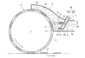
まず、図1を参照して、吸収マットの形成装置について、構成を述べる。
この装置で形成される吸収マット4には、パルプ繊維(繊維材料)4aおよび高吸水性樹脂(いわゆるSAP〈Superabsorbent polymer〉,高吸水性高分子あるいは高吸水性ポリマーとも称される)4bが含有される。たとえば、パルプ繊維4aによって拡散された液体を高吸水性樹脂4bが吸収し保持する。なお、パルプ繊維4aに替えてまたは加えて、繊維状のレーヨンやコットンといった繊維材料を用いてもよい。
[I. First embodiment]
[1. Constitution]
First, referring to FIG. 1, the configuration of an absorbent mat forming apparatus will be described.
ここでは、粒径分布の中央(以下「所定粒径」という)に一つのピークをもつ粉粒状の高吸水性樹脂4bが用いられる。言い換えれば、所定粒径の割合が多い高吸水性樹脂4bが用いられている。ただし、粒径分布に複数のピークをもつ高吸水性樹脂4bを用いてもよい。
高吸水性樹脂4bは、粒径が大きくなるほど、単位体積あたりの表面積(すなわち「比表面積」)が小さくなることから、液体の吸収速度が抑えられ、液体の保持量が高められる傾向にある。仮に、吸収マット4に高吸水性樹脂4bのみの層が形成されれば、この層ではゲルブロックが発生しやすくなる傾向にある。
Here, powdery
As the particle diameter of the
この形成装置には、パルプ繊維4aの供給路を形成する一つのダクト5と、ダクト5内部への高吸水性樹脂4bの供給路を形成する供給管7と、ダクト5および供給管7から供給されるパルプ繊維4aおよび高吸水性樹脂4bを外周2に積層して回転しながら吸収マット4を形成するドラム1とが設けられる。
In this forming apparatus, one
〈ダクト〉
ダクト5には、ドラム1の外周2の一部2a(図1では右上の外周縁部)を覆うように配置された下流端部5aに開口が設けられる。このダクト5は、下流端部5aに向けて広げられたスカート状に設けられる。また、ダクト5の内部では、粉砕あるいは解繊されたパルプ繊維4aが分散した状態でドラム1に向けて空気流で吹き付けられる。
<duct>
The
〈供給管〉
供給管7には、ダクト5の内部に配置された下流端部(ここでは下方)に開口が設けられる。この供給管7は、複数に分岐しており、分岐数に応じた数の開口を有するパイプ部材(「多岐管」や「マニホールド」などとも称される)である。これらの開口が高吸水性樹脂4bの供給口として設けられている。ここでは、供給管7が上下に延びて配置されている。
<Supply pipe>
The
なお、供給管7の上流端部(図示省略)は大気圧開放されている。これに対して、ダクト5の内部は、パルプ繊維4aが流通していることから大気圧よりも低い気圧となっている。そのため、大気圧とダクト5の内部の圧力(負圧)との差圧によって、高吸水性樹脂4bがダクト5の内部に引き込まれるようにして供給される。そのほか、重力によっても高吸水性樹脂4bがダクト5の内部に供給される。
The upstream end (not shown) of the
ここでは、ダクト5内部の分岐箇所Pで二つに分岐して二つの供給口11,21が設けられた供給管7を例示する。
この供給管7は、分岐箇所Pよりも上流側(ここでは上方)に設けられた一本の上流通路8と、分岐箇所Pよりも下流側(ここでは下方)で二つに分岐した分岐通路9とに大別される。
Here, the
The
この分岐通路9には、第一分岐通路(第一通路)10と第二分岐通路(第二通路)20とが設けられる。第一分岐通路10の下流端部には第一供給口11が設けられ、同様に、第二分岐通路20の下流端部には第二供給口21が設けられている。これらの供給口11,21は、ドラム1の外周2を向いて配置される。
The
供給口11,21から供給される高吸水性樹脂4bの量は、供給口11,21の開口面積S1,S2に応じたものとなる。なぜならば、「大気圧とダクト5の内部の圧力との差圧」と「開口面積S1,S2」とを乗じた吸引力で、空気とともに高吸水性樹脂4bが吸い出されるからである。そのため、供給口11,21の開口面積S1,S2の大小を調整することで、高吸水性樹脂4bの供給量を調整することができる。
The amount of the
なお、ここでいう「供給量」とは、単位時間あたりにダクト5の内部に供給される高吸水性樹脂4bの流量(すなわち「体積流量」)を意味する。
ここでは、第一供給口11の開口面積S1と第二供給口21の開口面積S2とが等しく設けられている。
Here, the “supply amount” means the flow rate (ie, “volume flow rate”) of the
Here, the opening area S 1 of the
また、供給口11,21がドラム1に対して外周で回転方向上流側に配置されるほど、供給口11,21から供給される高吸水性樹脂4bは、吸収マット4において厚み方向に満遍なく分布する傾向にある。なぜならば、ドラム1の回転方向上流側に向かうほど吸収マット4の積層が進んでおらず、回転方向上流側に配置された供給口11,21から供給された高吸水性樹脂4bが初期段階から吸収マット4として積層されるからである。
In addition, as the
具体的には、供給口11,21をドラム1に対して外周で回転方向上流側に配置するほど、吸収マット4の厚み方向においては、ドラム1の内周側(吸収マット4の深い側)から高吸水性樹脂4bが積層され、高吸水性樹脂4bがパルプ繊維4aに満遍なく混合される傾向にある。反対に、供給口11,21をドラム1に対して外周で回転方向下流側に配置するほど、吸収マット4の表面側(外周側)における高吸水性樹脂4bの密度が高まる傾向にある。このように、吸収マット4の厚み方向における高吸水性樹脂4bの密度分布(密度配向)は、ドラム1に対して外周で供給口11,21が配置される周方向位置に応じたものとなりうる。
ここでの供給口11,21は、周方向に沿って配置されている。具体的には、第二供給口21よりも第一供給口11のほうが、ドラム1に対して外周で回転方向下流側に配置されている。
Specifically, the more the
The
さらに、供給口11,21から供給される高吸水性樹脂4bは、ドラム1の外周2に対する供給口11,21の最短距離L1,L2が長いほど、パルプ繊維4aへの混合が促進され、吸収マット4の厚み方向に満遍なく分布する傾向にある。反対に、ドラム1の外周2に対する供給口11,21の最短距離L1,L2が短いほど、パルプ繊維4aへの高吸水性樹脂4bの混合が促進されず、吸収マット4において所定の層の密度が高まる傾向にある。ここでいう「所定の層」とは、ドラム1に対して外周に配置された供給口11,21の周方向位置に対応する吸収マット4の深さにおける層である。
Furthermore, the
ここでの供給口11,21は、ドラム1の外周2に対する最短距離Lが相違するように配置されている。具体的には、第一供給口11よりも第二供給口21のほうがドラム2に近接(ドラム1の外周2に対する第一供給口11の最短距離L1>ドラム1の外周2に対する第二供給口21の最短距離L2)して配置されている。
The
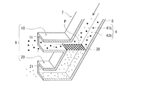
図1および図2に示すように、供給管7には、高吸水性樹脂4bを二つに分級する分級部30が設けられている。
分級部30は、篩状のメッシュ部材である。この分級部30のメッシュ(篩目開き)は、高吸水性樹脂4bの所定粒径に応じて設定される。具体的に言えば、所定粒径よりも大きい高吸水性樹脂4b(以下「大粒高吸水性樹脂41b」という)は通過することができず、所定粒径以下の高吸水性樹脂4b(以下「小粒高吸水性樹脂42b」という)は通過することができるメッシュが分級部30に採用される。そのため、高吸水性樹脂4bは、大粒高吸水性樹脂41bと小粒高吸水性樹脂42bとの二つに篩い分けられる。
As shown in FIGS. 1 and 2, the
The
この分級部30は、分岐通路9に設けられ、ダクト5の内部に配置される。ここでは、第二分岐通路20の上流端部において、高吸水性樹脂4bの流通方向に交差して分級部30が配置されている。具体的には、上流通路8における高吸水性樹脂4bの流通方向に対して、分級部30が傾斜して交差するように配置される。
分級部30によって分級された大粒高吸水性樹脂41bは、第一分岐通路10を流通して第一供給口11から排出される。また、分級部30によって分級された小粒高吸水性樹脂42bは、第二分岐通路20を流通して第二供給口21から排出される。
The classifying
The large
ただし、小粒高吸水性樹脂42bの中には、分級部30を通過しないものもあり、全ての小粒高吸水性樹脂42bが分級部30を通過するとは限らない。そのため、分級部30を通過しなかった小粒高吸水性樹脂42bは、第一供給口11から排出される。
たとえば、供給管7に供給される高吸水性樹脂4bは、ダクト5の内部に過不足なく供給されるようにするために、供給口11,21からダクト5内部への高吸水性樹脂41b,42bの各供給量に応じて、大粒高吸水性樹脂41bおよび小粒高吸水性樹脂42bの供給割合を設定することができる。
供給口11,21のそれぞれからダクト5の内部に排出され供給された高吸水性樹脂41b,42bは、ダクト5の内部で分散した状態のパルプ繊維4aに混合され、ドラム1に供給される。
However, some small
For example, the
The superabsorbent resins 41 b and 42 b discharged and supplied from the
〈ドラム〉
ドラム1は、供給されたパルプ繊維4aおよび高吸水性樹脂4bを内周側へ吸引して積重することで、吸収マット4を外周2に形成する円筒状の回転体である。このドラム1の外周2には、吸収マット4の概形に応じた形状の金型3が設けられており、金型3の内部に積重されたパルプ繊維4aおよび高吸水性樹脂4bが吸収マット4として形成される。
<drum>
The
図1では、右上の外周2の一部2aにパルプ繊維4aおよび高吸水性樹脂4bが供給され、反時計回りに回転するドラム1を例示する。ここでは、ドラム1の下部において、搬送ライン上に吸収マット4が受け渡されて載置される。
FIG. 1 illustrates a
[2.フローチャート]
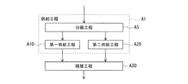
つづいて、図3を参照して、吸収マットの形成方法を説明する。この形成方法は、上述した形成装置によって吸収マット4を形成する方法である。
この形成方法では、供給工程(ステップA1),積層工程(ステップA20)の順に各工程を実施する。さらに、供給工程では、分級工程(ステップA5)の後に、第一供給工程(ステップA10)および第二供給工程(ステップA20)の二つの供給工程を並列的に実施する。
[2. flowchart]
Next, a method for forming the absorption mat will be described with reference to FIG. This forming method is a method of forming the
In this forming method, each process is performed in the order of the supplying process (step A1) and the stacking process (step A20). Further, in the supply process, after the classification process (step A5), the two supply processes of the first supply process (step A10) and the second supply process (step A20) are performed in parallel.
以下、順を追って各工程を説明する。
ステップA1の供給工程では、はじめに供給管7によって高吸水性樹脂4bをダクト5の内部に供給する。
この供給工程では、ステップA5の分級工程において、供給管7の分級部30によって、大粒高吸水性樹脂41bと小粒高吸水性樹脂42bとに高吸水性樹脂4bを篩い分けて二つに分級する。その後、ステップA10の第一供給工程とステップA20の第二供給工程とを同時に実施する。
Hereinafter, each step will be described in order.
In the supply step of Step A1, the
In this supplying process, in the classifying process of Step A5, the
第一供給工程では、第一分岐通路10の第一供給口11から大粒高吸水性樹脂41bをダクト5の内部に供給する。また、第二供給工程では、第二分岐通路20の第二供給口21から小粒高吸水性樹脂42bをダクト5の内部に供給する。
それから、ステップA30の積層工程では、ダクト5の内部に供給された高吸水性樹脂41b,42bの混合されたパルプ4aがドラム1の金型3に積層される。そして、吸収マット4が形成される。
In the first supply step, the large
Then, in the stacking process of Step A30, the
[3.作用および効果]
本実施形態の供給管および吸収マットの形成装置ならびに吸収マットの形成方法は、上述のように構成されるため、以下のような作用および効果を得ることができる。
〈供給管〉
まず、供給管7についての作用および効果を述べる。
[3. Action and effect]
Since the supply pipe, the absorbent mat forming apparatus, and the absorbent mat forming method of the present embodiment are configured as described above, the following operations and effects can be obtained.
<Supply pipe>
First, the operation and effect of the
(1)分級部30で分級された二種の高吸水性樹脂41b,42bは、粒径に応じて高吸水性樹脂41b,42bの流通する分岐通路10,20が類別され、それぞれに対応する分岐通路10,20を流通して供給口11,21からパルプ繊維4aが分散されたダクト5の内部に供給される。
そのため、ダクト5の内部において、パルプ繊維4aに対する高吸水性樹脂4bの混合領域や混合密度を、高吸水性樹脂4bの粒径に応じて調整することができる。パルプ繊維4aおよび高吸水性樹脂4bが積層される吸収マット4においても、パルプ繊維4aに対する高吸水性樹脂4bの混合領域や混合密度を、高吸水性樹脂4bの粒径に応じて調整することができる。
(1) The two types of
Therefore, in the
よって、高吸水性樹脂4bの積層状態を調整することができ、さまざまな吸液特性の吸収マット4を形成することができる。延いては、吸液特性を高めた吸収マット4を得ることができる。
また、粒径によらず全ての高吸水性樹脂4bは、分散されたパルプ繊維4aに混合されることから、吸収マット4に高吸水性樹脂4bのみの層が形成されることがない。そのため、ゲルブロックの発生を抑えることができる。この観点からも、吸収マット4の吸液性を高めることができる。
Therefore, the lamination state of the highly water-
Moreover, since all the
(2)ここでは、第一供給口11の開口面積S1と第二供給口21の開口面積S2とが等しく設けられているため、供給口11,21のそれぞれから同量あるいは略同量の高吸水性樹脂41b,42bがダクト5の内部に供給することができる。よって、大粒高吸水性樹脂41bの特性と小粒高吸水性樹脂42bの特定との双方を確実に併せもつ吸収マット4を形成することができる。たとえば、液体の拡散性を高めてゲルブロックの発生を抑えつつ、排泄された液体の吸収性と吸収された液体の保持性とを向上させた吸収マット4を積層することができる。
(2) Here, since the opening area S 1 of the
そのほか、高吸水性樹脂4bの流通方向に対して分級部30が傾斜して交差するように配置されるため、高吸水性樹脂4bを流通させる気流の分力によって分級部30に付着した高吸水性樹脂4bが吹き飛ばすことができる。よって、分級部30の目詰まりを抑えることができる。
なお、供給管7に供給される高吸水性樹脂4bとして、所定粒径およびこの周辺粒径の割合が小さいものを用いれば、分級部30の目詰まりを抑えることができる。
さらに、分級部30は、第二分岐通路20の上流端部に配置されることによっても、目詰まりが抑えられる。
In addition, since the
Note that if the
Furthermore, clogging is also suppressed by arranging the
〈吸収マットの形成装置〉
つぎに、吸収マットの形成装置についての作用および効果を述べる。この形成装置は、上記した(1)および(2)の作用および効果に加えて、下記の(3)〜(6)の作用および効果を得ることができる。
<Absorption mat forming device>
Next, operations and effects of the absorbent mat forming apparatus will be described. This forming apparatus can obtain the following operations (3) to (6) and effects in addition to the operations (1) and (2) described above.
(3)第二供給口21よりも第一供給口11のほうが、ドラム1に対して外周で回転方向下流側に配置される。そのため、第一供給口11からの大粒高吸水性樹脂41bは、第二供給口21からの小粒高吸水性樹脂42bよりも吸収マット4の表面側において高い密度で積層される。この高密度の大粒高吸水性樹脂41bによって、排泄された液体を確実に吸収して保持することができる。
(3) The
このように、吸収マット4の厚み方向において粒径ごとに高吸水性樹脂4bの密度を傾斜配向させることで、種々の吸液特性を得ることができる。
なお、第一供給口11の開口面積を小さくしたり、ドラム1に対する最短距離L1を長くすることで、吸収マット4の表面側への大粒高吸水性樹脂41bの供給量を減少させることで、大粒高吸水性樹脂41bによるゲルブロックの発生を確実に抑えることができる。
Thus, various liquid-absorbing characteristics can be obtained by tilting and orienting the density of the highly water-
In addition, by reducing the opening area of the
(4)また、ドラム1の外周2に対して、回転方向下流側の第一供給口11の最短距離L1よりも回転方向上流側の第二供給口21の最短距離L2のほうが短く設定されている。そのため、吸収マット4の所定の層において小粒高吸水性樹脂42bの密度を高めることができる。よって、多様な吸液特性の吸収マット4を形成することができる。
(4) The shortest distance L 2 of the
(5)ところで、従来の遠心分級機や慣性分級機といったサイクロン型の分級機は複雑あるいは大型である。このことから、従来の分級機は、供給管7の内部(特にダクト5の内部)への設置が困難である。
更に言えば、タンデム配置された形成装置のそれぞれに対して、従来の分級機で予め分級された高吸水性樹脂のそれぞれを供給すれば、吸収マットにおいて粒径ごとに高吸水性樹脂の混合領域や混合密度を調整することはできるものの、装置が複雑化あるいは大型化するという不具合がある。
(5) By the way, conventional cyclonic classifiers such as centrifugal classifiers and inertia classifiers are complicated or large. For this reason, the conventional classifier is difficult to install inside the supply pipe 7 (particularly inside the duct 5).
Furthermore, if each of the superabsorbent resins pre-classified with a conventional classifier is supplied to each of the forming devices arranged in tandem, the mixing region of the superabsorbent resin for each particle size in the absorbent mat Although the mixing density can be adjusted, there is a problem that the apparatus becomes complicated or large.
これに対して、篩状の分級部30は、簡素で小型な構成である。そのため、供給管7の内部に分級部30を設けることができる。また、供給管7において分級部30が設けられる分岐通路9をダクト5の内部に配置することができる。よって、形成装置をシングル配置すればよく、供給管7が設けられた形成装置の大型化や複雑化を抑えることができる。
なお、供給管7の第一供給口11に供給される高吸水性樹脂4bは、おもに大粒高吸水性樹脂41bであるものの一部に小粒高吸水性樹脂42bが混在しているが、吸収マット4において高吸水性樹脂4bの混合領域や混合密度を少なくとも調整することができる。
On the other hand, the
The
(6)また、従来の吸収性物品には、吸収マットの肌面側に対して、液体の拡散性を高めるための液拡散シート(「セカンドシート」や「ADL〈Acquisition Distribution Layer〉」などとも称される)が積層される場合がある。
これに対して、本実施形態の吸収マット4によれば、上述したように粒径に応じた高吸水性樹脂4bの混合領域や混合密度を調整することで、吸収マット4の肌面側における液体の拡散性を向上させることができる。そのため、吸収性物品から液拡散シートを省略することもできる。
(6) In addition, conventional absorbent articles include a liquid diffusion sheet (“second sheet”, “ADL <Acquisition Distribution Layer>”, etc.) for increasing the liquid diffusibility with respect to the skin surface side of the absorbent mat. May be stacked.
On the other hand, according to the
そのほか、粒径に応じた高吸水性樹脂4bの混合領域や混合密度を調整することにより、液体の吸収性やその保持性を高めることで、高吸水性樹脂4bの使用量を低減させることができ、材料コストを抑えることができる。
In addition, by adjusting the mixing region and the mixing density of the
〈吸収マットの形成方法〉
なお、吸収マットの形成方法についても、上記した(1)〜(6)と同様の作用および効果を得ることができる。
<Method for forming absorbent mat>
In addition, also about the formation method of an absorption mat, the effect | action and effect similar to above-mentioned (1)-(6) can be acquired.
[I′.第一実施形態の変形例]
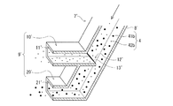
つぎに、図4を参照して、第一実施形態の変形例を説明する。なお、ここで説明する点を除いては第一実施形態と同様の構成になっている。これらの構成については、同様の符号を付し、各部の説明を省略する。
この変形例の供給管7′は、上述した第一実施形態の供給管7に対して、上流通路8′よりも下流の分岐通路9′の構成が異なる。具体的には、第一分岐通路10′の上流端部12′に分級部30′が設けられ、この上流端部12′に突出部13′が設けられる点が異なる。
[I '. Modification of First Embodiment]
Next, a modification of the first embodiment will be described with reference to FIG. The configuration is the same as that of the first embodiment except for the points described here. About these structures, the same code | symbol is attached | subjected and description of each part is abbreviate | omitted.
The supply pipe 7 'of this modification is different from the
第一分岐通路10′には、上流端部12′の一部が突出した突出部13′が設けられる。この突出部13′は、上流端部12′のうち下方の一部でリップ状に突出している。なお、上流端部12′の上方は、突出部13′の先端よりも基端側(ここでは左方)に配置される。
分級部30′は、高吸水性樹脂4bの流通方向に交差して配置される。具体的には、第一分岐通路10′の上流端部12′において、突出部13′の基端部と先端部とを結ぶ方向かつ上下方向に沿って分級部30′が配置される。
The first branch passage 10 'is provided with a protruding portion 13' from which a part of the upstream end portion 12 'protrudes. The protruding portion 13 'protrudes in a lip shape at a part of the lower portion of the upstream end portion 12'. In addition, the upper end of the upstream end portion 12 'is disposed on the base end side (here, the left side) with respect to the distal end of the protruding portion 13'.
The
このように供給管7′が構成されることで、第一分岐通路10′の第一供給口11′から小粒高吸水性樹脂42bを供給することができる。また、第二分岐通路20′の第二供給口21′から大粒高吸水性樹脂41bおよび分級部30′を通過しなかった小粒高吸水性樹脂42bを供給することができる。
By configuring the supply pipe 7 'in this way, the small
この場合には、上述した第一実施形態の供給管7による作用および効果について、「大粒高吸水性樹脂41b」を「小粒高吸水性樹脂42b」と読み替え、「小粒高吸水性樹脂42b」を「大粒高吸水性樹脂41b」と読み替えた作用および効果を得ることができる。
よって、吸収マット4の吸液特性を幅広く調整することができる。
In this case, with respect to the action and effect of the
Therefore, the liquid absorption characteristics of the
たとえば、上述した第一実施形態の供給管7とは反対に、吸収マット4の表面側における大粒高吸水性樹脂41bのパルプ繊維4aへの混合密度が抑えられる。そのため、液体の拡散性を確保することができ、吸収マット4を全体的に使って吸液させることができる。
ここで、吸収マット4の表面側が肌面側であれば、この表面側における大粒高吸水性樹脂41bの過密化が抑えられ、吸液速度を高めて液漏れを確実に抑えることができる。
For example, contrary to the
Here, if the surface side of the
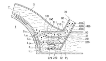
[II.第二実施形態]
つぎに、図5を参照して、第二実施形態を説明する。なお、ここで説明する点を除いては第一実施形態と同様の構成になっている。これらの構成については、各部の説明を省略する。
[1.構成]
第二実施形態の供給管70は、第一実施形態の供給管7が二つに分岐して一つの分級部30が設けられるのに対して、三つに分岐して二つの分級部31,32が設けられる点が異なる。
[II. Second embodiment]
Next, a second embodiment will be described with reference to FIG. The configuration is the same as that of the first embodiment except for the points described here. Explanation of each part is omitted about these composition.
[1. Constitution]
In the
具体的には、上流通路80よりも下流の分岐通路90が、第一分岐箇所P1で第一分岐通路(第一通路)100および第二分岐通路(第二通路)200に分岐したうえで、第二分岐通路200が第二分岐箇所P2で複数の副通路に分岐している。
この分岐通路200には、第二分岐箇所P2よりも上流側の主通路201と、第二分岐箇所P2よりも下流で二つに分岐した第一副通路(第一通路)210および第二副通路(第二通路)220とが設けられている。
Specifically, the
The
第一分岐通路100の下流端部には第一供給口101が設けられる。また、第二分岐通路200には、第一副通路210の下流端部に第一副供給口(第一供給口,第二供給口)211と、第二副通路220の下流端部に第二副供給口(第二供給口)221とが設けられる。
ここでは、供給口101,211,221の開口面積S11,S21,S22が互いに相違している。具体的には、第一供給口101の開口面積S11,第一副供給口211の開口面積S21,第二副供給口221の開口面積S22の順に小さくなる(S11>S21>S22)ように設けられている。
A
Here, the opening areas S 11 , S 21 , and S 22 of the
また、供給口101,211,221は、周方向に沿って配置されている。具体的には、ドラム1に対して外周で回転方向上流側から下流側へ向けて、第二副供給口221,第一副供給口211,第一供給口101の順に配置されている。
さらに、供給口101,211,221は、ドラム1の外周2に対する最短距離L11,L21,L22が等しく(L11=L21=L22)なるように配置されている。
The
Further, the
二つの分級部31,32は、分岐通路90に設けられる。具体的には、主通路201の上流端部に第一分級部31が配置され、第二副通路220の上流端部に第二分級部32が配置される。なお、第一分岐通路100および第一副通路210には分級部が設けられていない。
この第二分級部32のメッシュには、第一分級部31のメッシュよりも小さいものが用いられる。
The two
As the mesh of the second classifying
具体的に言えば、第一所定粒径よりも大きい高吸水性樹脂40b(以下「大粒高吸水性樹脂410b」という)は通過することができず、第一所定粒径以下の高吸水性樹脂4bは通過することができるメッシュが第一分級部31に採用される。また、第一所定粒径よりも小さく第二所定粒径よりも大きい高吸水性樹脂40b(以下「中粒高吸水性樹脂420b」という)は通過することができず、第二所定粒径以下の高吸水性樹脂(以下「小粒高吸水性樹脂430b」という)は通過することができるメッシュが第二分級部32に採用される。
Specifically, the superabsorbent resin 40b larger than the first predetermined particle diameter (hereinafter referred to as “large
この場合、供給管70に供給される高吸水性樹脂4bには、粒径分布に三つのピークをもつものを用いることができる。たとえば、三つのピークを粒径が大きい順に第一ピーク,第二ピーク,第三ピークとしたときに、第一ピークの中央値が第一所定粒径よりも大きく、第二ピークの中央値が第一所定粒径よりも小さいとともに第二所定粒径よりも大きく、第三ピークの中央値が第二所定粒径よりも小さいことが好ましい。
さらに、供給管7に供給される高吸水性樹脂40bは、ダクト5の内部に過不足なく供給されるようにするために、供給口101,211,221からの高吸水性樹脂410b,420b,430bの各供給量に応じて、大粒高吸水性樹脂410b,中粒高吸水性樹脂420bおよび小粒高吸水性樹脂430bの供給割合を設定することができる。
In this case, as the
Further, the superabsorbent resin 40b supplied to the
高吸水性樹脂4bは、第一分級部31によって、大粒高吸水性樹脂410bと中粒高吸水性樹脂420bおよび小粒高吸水性樹脂430bとの二つに篩い分けられる。大粒高吸水性樹脂410bは、第一分岐通路100を流通して第一供給口110から排出される。なお、第一分級部31を通過しなかった中粒高吸水性樹脂420bおよび小粒高吸水性樹脂430bも第一供給口110から排出される。
The
中粒高吸水性樹脂420bおよび小粒高吸水性樹脂430bは、第二分岐通路200の第二分級部32によって、中粒高吸水性樹脂420bと小粒高吸水性樹脂430bとの二つに篩い分けられる。
中粒高吸水性樹脂420bは、第二分岐通路200の第一副通路210を流通して第一副供給口211から排出される。なお、第二分級機32を通過しなかった小粒高吸水性樹脂430bも第一副供給口211から排出される。
小粒高吸水性樹脂430bは、第二分岐通路200の第二副通路220を流通して第二副供給口221から排出される。
The medium-sized high water-absorbing resin 420b and the small-sized high water-absorbing
The medium grain high water-absorbing resin 420 b flows through the
The small
[2.作用および効果]
本実施形態は、上述のように構成されるため、第一実施形態と同様の作用および効果に加えて、以下のような作用および効果を得ることができる。
〈供給管〉
まず、供給管70についての作用および効果を述べる。
[2. Action and effect]
Since this embodiment is configured as described above, the following actions and effects can be obtained in addition to the actions and effects similar to those of the first embodiment.
<Supply pipe>
First, the operation and effect of the
(1)第一分級部31で分級された中粒高吸水性樹脂420bおよび小粒高吸水性樹脂430bは、第二分岐通路200で分岐した二つの副通路210,220を流通して副供給口211,221からダクト5の内部へ供給される。そのため、第一分級部31で分級された高吸水性樹脂420b,430bのパルプ繊維4bへの混合領域や混合密度をより細やかに調整することができる。よって、多様な吸液特性の吸収マット4を得ることができる。
(1) The medium-sized high water-absorbing resin 420b and the small-sized high water-absorbing
(2)第二分岐通路200の上流側に第一分級部31が設けられ、この第二分岐通路200においては、第一副通路210に分級部が設けられず、第二副通路220に第二分級部32が設けられている。これらの分級部31,32は、下流のものほど粒径の小さい高吸水性樹脂4bに分級する。そのため、高吸水性樹脂4bは、供給管70を流通するにしたがって、粒径の小さい高吸水性樹脂410b,420b,430bに順次分級される。したがって、粒径ごとに細かく類別された高吸水性樹脂4bのそれぞれを各供給口101,211,221から供給することができる。よって、種々の吸液特性の吸収マット4を得ることができる。
(2) The
(3)ここでは、第一供給口101の開口面積S11,第一副供給口211の開口面積S21,第二副供給口221の開口面積S22の順に小さくなるように設けられている。そのため、高吸水性樹脂4bの供給量は、粒径が大きくなるほど多くなる(大粒高吸水性樹脂410bの供給量>中粒高吸水性樹脂420bの供給量>小粒高吸水性樹脂430bの供給量)。したがって、高吸水性樹脂4bのうち、液体の吸収量あるいは保持量に優れた粒径の大きい高吸水性樹脂4bの供給割合を高めることができる。よって、吸液特性を高めた吸収マット4を得ることができる。
(3) Here, the opening area S 11 of the
〈吸収マットの形成装置〉
つぎに、吸収マットの形成装置についての作用および効果を述べる。この形成装置は、上記した(1)〜(3)の作用および効果に加えて、下記の(4)および(5)の作用および効果を得ることができる。
<Absorption mat forming device>
Next, operations and effects of the absorbent mat forming apparatus will be described. This forming apparatus can obtain the following actions and effects (4) and (5) in addition to the actions and effects (1) to (3) described above.
(4)ドラム1に対して外周で回転方向上流側から下流側へ向けて、第二副供給口221,第一副供給口211,第一供給口101の順に配置されている。そのため、吸収マット4の表面側における高吸水性樹脂4bの密度は、粒径が大きいほど高くなる傾向にある(小粒高吸水性樹脂430bの密度<中粒高吸水性樹脂420bの密度<大粒高吸水性樹脂410bの密度)。そのため、吸収マット4の表面側における液体の保持量を高めることに寄与する。このようにして、多様な吸液特性の吸収マット4を形成することができる。
(4) The second
(5)供給口101,211,221は、ドラム1の外周2に対する最短距離L11,L21,L22が等しく(L11=L21=L22)なるように配置されている。そのため、三つの異なる所定の層において、各高吸水性樹脂410b,420b,430bの密度を均すことができる。よって、さまざまな吸液特性の吸収マット4を形成することができる。
(5) The
[III.その他]
最後に、その他の実施形態について述べる。
供給管には、第一分岐通路に複数の副通路が設けられてもよいし、これらの副通路のうち少なくとも一つを除く副通路のそれぞれに分級部が設けられてもよい。この場合の第一分岐通路に設けられた分級部には、異なる粒径(たとえば下流のものほど大きい)に高吸水性樹脂を分級するものを用いることができる。
[III. Others]
Finally, other embodiments will be described.
In the supply pipe, a plurality of sub passages may be provided in the first branch passage, and a classification portion may be provided in each of the sub passages excluding at least one of these sub passages. In this case, as the classifying portion provided in the first branch passage, one that classifies the highly water-absorbent resin to different particle sizes (for example, the larger the downstream one) can be used.
たとえば、図6に示すような供給管70″を用いてもよい。
この供給管70″の分岐通路90″は、第一分岐通路100″と第二分岐通路200″との二つに第一分岐箇所P1″で分岐している。第一分岐通路100″は、三つの副通路110″,120″,130″に分岐しており、第二分岐通路200″は、二つの副通路210″,220″に分岐している。
For example, a
"
第一分岐通路100″では、第二分岐箇所P2″で第一副通路110″と第二副通路120″および第三副通路130″とに分岐し、この第二分岐箇所P2″よりも下流の第三分岐箇所P3″で第二副通路120″と第三副通路130″とに分岐している。また、第二分岐通路200″では、第四分岐通路P4″で第一副通路210″と第二副通路220″とに分岐している。
In the
ここでは、第一分岐通路100″における副通路110″,120″,130″の供給口111″,121″,131″が軸方向に沿って配置され、同様に、第二分岐通路200″における副通路210″,220″の供給口211″,221″が軸方向に沿って配置される。なお、第一分岐通路100″の供給口111″,121″,131″と第二分岐通路200″の供給口211″,221″とは周方向に沿って配置される。
第一分岐通路100″では、第一副通路110″の上流端部に第一分級部31″が設けられ、第二副通路120″の上流端部に第二分級部32″が設けられ、第三副通路130″には分級部が設けられていない。
Here, the
In the
また、第二分岐通路200″の上流端部には、第三分級部33″が設けられ、第一副通路210″の上流端部に第四分級部34″が設けられ、第二副通路220″には分級部が設けられていない。
ここでは、第一分級部31″のメッシュを「M1」とし、第二分級部32″のメッシュを「M2」とし、第三分級部33″のメッシュを「M3」とし、第二分級部34″のメッシュを「M4」としたときに、不等式「M4<M3<M1<M2」を満たすように各分級部31″,32″,33″,34″のメッシュが設定されている。
Further, a third classifying
Here, the mesh of the
すなわち、第一分岐通路100″では、下流のものほど粒径の大きい高吸水性樹脂4bに分級する分級部31″,32″が用いられ、反対に、第二分岐通路200″では、下流のものほど粒径の小さい高吸水性樹脂4bに分級する分級部33″,34″が用いられている。
このような供給管70″によれば、高吸水性樹脂の粒径をより多段階(ここでは五段階)に分級することができ、高吸水性樹脂の混合範囲や混合領域を細密に調整することができる。よって、多種多様な吸液特性の吸液マットを形成することができる。
That is, in the
According to such a
また、第一分岐通路100″の供給口111″,121″,131″や第二分岐通路200″の供給口211″,221″が軸方向に沿って配置される。そのため、吸収マット4の軸方向における高吸水性樹脂4bの密度を粒径ごとに調整することができる。
この軸方向が、吸収マット4の幅方向(長手方向と厚み方向に直交する方向)に対応していれば、吸収マット4の幅方向において高吸水性樹脂4bの粒径ごとに混合密度や混合領域を調整することができる。たとえば、幅方向中央において粒径の大きい高吸水性樹脂の密度を高めることで、吸収マット4の吸液特性を向上させることができる。
Further, the
If this axial direction corresponds to the width direction of the absorbent mat 4 (the direction perpendicular to the longitudinal direction and the thickness direction), the mixing density and mixing for each particle diameter of the
そのほか、第一実施形態および第二実施形態で上述した供給管7,7′,70が取り付けられる姿勢は、上下に延びて配置されるものに限らず、任意の方向に設定することができる。たとえば、供給管7,7′,70を水平に延びるように配置してもよい。この場合には、供給口11,11′,21,21′,101,211,221が軸方向に沿って配置されうる。
なお、分級部としては、篩状に形成される構造のほか、サイクロン型の分級機を用いてもよい。
In addition, the posture in which the
In addition, as a classification part, you may use a cyclone classifier other than the structure formed in a sieve shape.
1 ドラム
2 外周
2a 一部
3 金型
4 吸収マット
4a パルプ繊維(繊維材料)
4b 高吸水性樹脂
41b 大粒高吸水性樹脂
42b 小粒高吸水性樹脂
5 ダクト
5a 下流端部
7 供給管
8 上流通路
9 分岐通路
10 第一分岐通路(第一通路)
11 第一供給口
20 第二分岐通路(第二通路)
21 第二供給口
30 分級部
L1 ドラム1に対する第一供給口11の最短距離
L2 ドラム1に対する第二供給口21の最短距離
P 分岐箇所(一箇所)
S1 第一供給口11の開口面積
S2 第二供給口21の開口面積
DESCRIPTION OF
11
21
S 1 Opening area of the first supply port 11 S 2 Opening area of the
Claims (12)
前記高吸水性樹脂を少なくとも二つに分級する分級部と、
前記分級部で分級された一方の前記高吸水性樹脂を第一供給口から供給する第一通路と、
前記分級部で分級された他方の前記高吸水性樹脂を第二供給口から供給する第二通路と
を備えたことを特徴とする供給管。 In a forming apparatus for forming an absorbent mat having a superabsorbent resin mixed with a fiber material, a supply pipe for supplying the superabsorbent resin into a duct in which the fibrous material is dispersed,
A classifying unit for classifying the superabsorbent resin into at least two;
A first passage for supplying one of the superabsorbent resins classified by the classification unit from a first supply port;
A supply pipe, comprising: a second passage for supplying the other superabsorbent resin classified by the classification unit from a second supply port.
ことを特徴とする請求項1に記載された供給管。 The supply pipe according to claim 1, wherein the first passage or the second passage has a plurality of branched sub-passages.
ことを特徴とする請求項2に記載された供給管。 3. The classification part is provided in the sub-passage except at least one of the plurality of sub-passages, and each of the classification parts classifies the superabsorbent resin into different particle sizes. Supply pipe as described in.
ことを特徴とする請求項1〜3の何れか1項に記載された供給管。 The supply pipe according to any one of claims 1 to 3, wherein an opening area of the first supply port is equal to an opening area of the second supply port.
ことを特徴とする請求項1〜3の何れか1項に記載された供給管。 The supply pipe according to any one of claims 1 to 3, wherein an opening area of the first supply port is different from an opening area of the second supply port.
前記ダクトで外周の一部が覆われ、前記繊維材料および前記高吸水性樹脂を前記外周の一部に積層して前記吸収マットを形成するドラムと
を備えたことを特徴とする吸収マットの形成装置。 A supply pipe according to any one of claims 1 to 5;
A part of an outer periphery is covered with the duct, and a drum for forming the absorbent mat by laminating the fiber material and the superabsorbent resin on a part of the outer periphery is provided. apparatus.
ことを特徴とする請求項6に記載された吸収マットの形成装置。 The said 1st supply port and said 2nd supply port are arrange | positioned along the circumferential direction of the said drum, The formation apparatus of the absorption mat described in Claim 6 characterized by the above-mentioned.
ことを特徴とする請求項6または7に記載された吸収マットの形成装置。 The absorbent mat forming apparatus according to claim 6 or 7, wherein the first supply port and the second supply port are arranged along an axial direction of the drum.
ことを特徴とする請求項6〜8の何れか1項に記載された吸収マットの形成装置。 9. The shortest distance of the first supply port with respect to a part of the outer periphery and a shortest distance of the second supply port with respect to a part of the outer periphery are different from each other. Absorbent mat forming device.
ことを特徴とする請求項6〜8の何れか1項に記載された吸収マットの形成装置。 The shortest distance of the first supply port with respect to a part of the outer periphery and the shortest distance of the second supply port with respect to a part of the outer periphery are equal to each other. Absorbent mat forming device.
ことを特徴とする請求項6〜10の何れか1項に記載された吸収マットの形成装置。 The said classification | category part is arrange | positioned inside the said duct, The formation apparatus of the absorbent mat described in any one of Claims 6-10 characterized by the above-mentioned.
前記供給工程は、
前記高吸水性樹脂を少なくとも二つに分級する分級工程と、
前記分級工程で分級された一方の前記高吸水性樹脂を供給する第一供給工程と、
前記分級工程で分級された他方の前記高吸水性樹脂を供給する第二供給工程と
を有することを特徴とする吸収マットの形成方法。 A supply step of supplying a superabsorbent resin into the duct in which the fiber material is dispersed;
The supply step includes
A classification step of classifying the superabsorbent resin into at least two;
A first supply step of supplying one of the superabsorbent resins classified in the classification step;
And a second supply step of supplying the other superabsorbent resin classified in the classification step.
Priority Applications (1)
| Application Number | Priority Date | Filing Date | Title |
|---|---|---|---|
| JP2016084719A JP6601304B2 (en) | 2016-04-20 | 2016-04-20 | Supply pipe, absorption mat forming apparatus, and absorption mat forming method |
Applications Claiming Priority (1)
| Application Number | Priority Date | Filing Date | Title |
|---|---|---|---|
| JP2016084719A JP6601304B2 (en) | 2016-04-20 | 2016-04-20 | Supply pipe, absorption mat forming apparatus, and absorption mat forming method |
Publications (2)
| Publication Number | Publication Date |
|---|---|
| JP2017192568A true JP2017192568A (en) | 2017-10-26 |
| JP6601304B2 JP6601304B2 (en) | 2019-11-06 |
Family
ID=60155715
Family Applications (1)
| Application Number | Title | Priority Date | Filing Date |
|---|---|---|---|
| JP2016084719A Expired - Fee Related JP6601304B2 (en) | 2016-04-20 | 2016-04-20 | Supply pipe, absorption mat forming apparatus, and absorption mat forming method |
Country Status (1)
| Country | Link |
|---|---|
| JP (1) | JP6601304B2 (en) |
Citations (8)
| Publication number | Priority date | Publication date | Assignee | Title |
|---|---|---|---|---|
| JPH0725976U (en) * | 1993-10-18 | 1995-05-16 | エヌオーケー株式会社 | Classifier |
| JPH07289589A (en) * | 1994-03-28 | 1995-11-07 | Kimberly Clark Corp | Device and method to accumulate granular material on composite carrier |
| JPH11513080A (en) * | 1995-08-25 | 1999-11-09 | ザ、プロクター、エンド、ギャンブル、カンパニー | Apparatus for classifying base components according to particle size and method for classifying base components with the apparatus |
| JP2001171029A (en) * | 1999-12-22 | 2001-06-26 | Kao Corp | Method for producing particle deposit |
| US6416697B1 (en) * | 1999-12-03 | 2002-07-09 | Kimberly-Clark Worldwide, Inc. | Method for obtaining a dual strata distribution of superabsorbent in a fibrous matrix |
| JP2008206539A (en) * | 2007-02-23 | 2008-09-11 | Kao Corp | Absorber manufacturing method |
| JP2008284182A (en) * | 2007-05-18 | 2008-11-27 | Kao Corp | Absorber manufacturing method |
| JP2009114555A (en) * | 2007-11-01 | 2009-05-28 | Kao Corp | Deposited body manufacturing method and manufacturing apparatus |
-
2016
- 2016-04-20 JP JP2016084719A patent/JP6601304B2/en not_active Expired - Fee Related
Patent Citations (8)
| Publication number | Priority date | Publication date | Assignee | Title |
|---|---|---|---|---|
| JPH0725976U (en) * | 1993-10-18 | 1995-05-16 | エヌオーケー株式会社 | Classifier |
| JPH07289589A (en) * | 1994-03-28 | 1995-11-07 | Kimberly Clark Corp | Device and method to accumulate granular material on composite carrier |
| JPH11513080A (en) * | 1995-08-25 | 1999-11-09 | ザ、プロクター、エンド、ギャンブル、カンパニー | Apparatus for classifying base components according to particle size and method for classifying base components with the apparatus |
| US6416697B1 (en) * | 1999-12-03 | 2002-07-09 | Kimberly-Clark Worldwide, Inc. | Method for obtaining a dual strata distribution of superabsorbent in a fibrous matrix |
| JP2001171029A (en) * | 1999-12-22 | 2001-06-26 | Kao Corp | Method for producing particle deposit |
| JP2008206539A (en) * | 2007-02-23 | 2008-09-11 | Kao Corp | Absorber manufacturing method |
| JP2008284182A (en) * | 2007-05-18 | 2008-11-27 | Kao Corp | Absorber manufacturing method |
| JP2009114555A (en) * | 2007-11-01 | 2009-05-28 | Kao Corp | Deposited body manufacturing method and manufacturing apparatus |
Also Published As
| Publication number | Publication date |
|---|---|
| JP6601304B2 (en) | 2019-11-06 |
Similar Documents
| Publication | Publication Date | Title |
|---|---|---|
| RU2530147C1 (en) | Method and device for transfer of substrate material and particulate material | |
| CN105556016B (en) | Product fibre device | |
| JP5019906B2 (en) | Absorber manufacturing method | |
| CN101686888B (en) | Absorbent structure | |
| US20060202380A1 (en) | Method of making absorbent core structures with undulations | |
| CN104379101B (en) | Fiber accumulations device | |
| CN1492751A (en) | Liquid distribution unit and absorbent article having the same | |
| JPS6192859A (en) | Method and device for uniformly distributing severally separated particle onto moving porous web | |
| KR101853034B1 (en) | Absorbent article with mechanical apparel attachment | |
| US20060206074A1 (en) | Absorbent core structures having undulations | |
| CN105813609B (en) | Absorbent Manufacturing Equipment | |
| JP6378624B2 (en) | Absorbent articles | |
| TWI617297B (en) | Absorber manufacturing device | |
| CN105764459B (en) | The manufacturing device of absorber | |
| JP6601304B2 (en) | Supply pipe, absorption mat forming apparatus, and absorption mat forming method | |
| JP6812153B2 (en) | Absorber manufacturing equipment and absorber manufacturing method | |
| JP5989061B2 (en) | Absorber manufacturing apparatus and manufacturing method | |
| JP2016008367A (en) | Non-woven fabric | |
| JP2008154774A (en) | Absorber | |
| JP5457507B2 (en) | Fiber stacking equipment | |
| JP5989062B2 (en) | Absorber manufacturing equipment | |
| JP2016104054A (en) | Manufacturing device for absorbent body | |
| JPWO2019069385A1 (en) | Absorber and absorbent article manufacturing method, and absorbent body and absorbent article manufacturing apparatus | |
| JP6683795B1 (en) | Absorber manufacturing method and manufacturing apparatus | |
| WO2015079964A1 (en) | Manufacturing device for absorbent body |
Legal Events
| Date | Code | Title | Description |
|---|---|---|---|
| A621 | Written request for application examination |
Free format text: JAPANESE INTERMEDIATE CODE: A621 Effective date: 20180516 |
|
| A977 | Report on retrieval |
Free format text: JAPANESE INTERMEDIATE CODE: A971007 Effective date: 20190208 |
|
| A131 | Notification of reasons for refusal |
Free format text: JAPANESE INTERMEDIATE CODE: A131 Effective date: 20190319 |
|
| A521 | Request for written amendment filed |
Free format text: JAPANESE INTERMEDIATE CODE: A523 Effective date: 20190507 |
|
| TRDD | Decision of grant or rejection written | ||
| A01 | Written decision to grant a patent or to grant a registration (utility model) |
Free format text: JAPANESE INTERMEDIATE CODE: A01 Effective date: 20190910 |
|
| A61 | First payment of annual fees (during grant procedure) |
Free format text: JAPANESE INTERMEDIATE CODE: A61 Effective date: 20190923 |
|
| R150 | Certificate of patent or registration of utility model |
Ref document number: 6601304 Country of ref document: JP Free format text: JAPANESE INTERMEDIATE CODE: R150 |
|
| R250 | Receipt of annual fees |
Free format text: JAPANESE INTERMEDIATE CODE: R250 |
|
| R250 | Receipt of annual fees |
Free format text: JAPANESE INTERMEDIATE CODE: R250 |
|
| LAPS | Cancellation because of no payment of annual fees |