JP2017192548A - Eyewear, information processing method, and program - Google Patents
Eyewear, information processing method, and program Download PDFInfo
- Publication number
- JP2017192548A JP2017192548A JP2016084423A JP2016084423A JP2017192548A JP 2017192548 A JP2017192548 A JP 2017192548A JP 2016084423 A JP2016084423 A JP 2016084423A JP 2016084423 A JP2016084423 A JP 2016084423A JP 2017192548 A JP2017192548 A JP 2017192548A
- Authority
- JP
- Japan
- Prior art keywords
- signal
- electrode
- difference
- predetermined range
- nose
- Prior art date
- Legal status (The legal status is an assumption and is not a legal conclusion. Google has not performed a legal analysis and makes no representation as to the accuracy of the status listed.)
- Pending
Links
Images
Landscapes
- Eye Examination Apparatus (AREA)
- Measuring And Recording Apparatus For Diagnosis (AREA)
- Measurement And Recording Of Electrical Phenomena And Electrical Characteristics Of The Living Body (AREA)
Abstract
Description
本発明は、アイウエア、情報処理方法、及びプログラムに関する。 The present invention relates to eyewear, an information processing method, and a program.
従来、右、左のノーズパッドそれぞれに、2つの電極を設け、その電極を用いて眼電位を検出するアイウエアが知られている(例えば、特許文献1参照)。 Conventionally, eyewear is known in which two electrodes are provided on each of the right and left nose pads and the electrooculogram is detected using the electrodes (see, for example, Patent Document 1).
ここで、通常のノーズパッドは、平らな形状、もしくは、鼻に接触する面が緩やかな凸形状となっており、ノーズパッド内の1つの領域が鼻に接触する傾向にある。しかしながら、ノーズパッド内に設けられた2つの電極を用いて眼電位が検出される際、2つの電極は装着時に鉛直方向にできるだけ離間されて設けられるため、1つの領域が鼻に接触する状況では、一方の電極が鼻に接触するときに、他方の電極が鼻に接触しなかったり、接触不良となったりすることがあった。この場合、適切な眼電位信号を取得することが困難になってしまう。 Here, the normal nose pad has a flat shape or a convex shape with a gentle surface in contact with the nose, and one region in the nose pad tends to contact the nose. However, when the electrooculogram is detected using two electrodes provided in the nose pad, the two electrodes are provided as far apart as possible in the vertical direction at the time of wearing, so in a situation where one region contacts the nose. When one electrode contacts the nose, the other electrode may not contact the nose or may have poor contact. In this case, it becomes difficult to acquire an appropriate electrooculogram signal.
そこで、本発明は、ノーズパッドに複数の電極が設けられる際、適切な眼電位信号を取得することを目的の一つとする。 Accordingly, an object of the present invention is to obtain an appropriate electrooculogram signal when a plurality of electrodes are provided on a nose pad.
本発明の一態様におけるアイウエアは、フレームと、前記フレームに接続される一対のノーズパッドであって、それぞれの上端部及び下端部に電極を有する一対のノーズパッドと、前記一対のノーズパッドの前記上端部の電極同士を電気的に接続する部材と、を有する。 The eyewear according to one aspect of the present invention includes a frame, a pair of nose pads connected to the frame, a pair of nose pads each having an electrode at an upper end portion and a lower end portion, and the pair of nose pads. A member that electrically connects the electrodes at the upper end.
また、本発明の他の態様におけるアイウエアは、上端部の第1電極及び下端部の第2電極を有する右ノーズパッドと、上端部の第3電極及び下端部の第4電極を有する左ノーズパッドと、処理部と、を備えるアイウエアであって、前記処理部は、前記第1電極に基づく第1信号、前記第2電極に基づく第2信号、前記第3電極に基づく第3信号、及び前記第4電極に基づく第4信号を取得し、前記第1信号及び前記第3信号が、所定範囲内であるか否かを判定し、前記第1信号及び前記第3信号が前記所定範囲内であれば、前記第1信号と前記第2信号との差分を示す第1差分信号、及び前記第3信号と前記第4信号との差分を示す第2差分信号を算出し、前記第1信号及び前記第3信号のいずれか1つのみが前記所定範囲内であれば、前記第2信号及び前記第4信号それぞれと、前記所定範囲内の前記第1信号又は前記第3信号との差分を示す第1差分信号及び第2差分信号を算出し、前記第1差分信号及び前記第2差分信号を出力する。 The eyewear according to another aspect of the present invention includes a right nose pad having a first electrode at the upper end and a second electrode at the lower end, and a left nose having a third electrode at the upper end and a fourth electrode at the lower end. An eyewear comprising a pad and a processing unit, wherein the processing unit includes a first signal based on the first electrode, a second signal based on the second electrode, a third signal based on the third electrode, And obtaining a fourth signal based on the fourth electrode, determining whether the first signal and the third signal are within a predetermined range, and determining whether the first signal and the third signal are within the predetermined range. The first difference signal indicating a difference between the first signal and the second signal, and a second difference signal indicating a difference between the third signal and the fourth signal, and calculating the first difference signal. If only one of the signal and the third signal is within the predetermined range, Calculating a first difference signal and a second difference signal indicating a difference between each of the two signals and the fourth signal and the first signal or the third signal within the predetermined range, and calculating the first difference signal and the first signal. 2 The difference signal is output.
本発明の態様によれば、ノーズパッドに複数の電極が設けられる際、適切な眼電位信号を取得することができる。 According to the aspect of the present invention, an appropriate electrooculogram signal can be acquired when a plurality of electrodes are provided on a nose pad.
以下、図面を参照して本発明の実施の形態を説明する。ただし、以下に説明する実施形態は、あくまでも例示であり、以下に明示しない種々の変形や技術の適用を排除する意図はない。即ち、本発明は、その趣旨を逸脱しない範囲で種々変形して実施することができる。また、以下の図面の記載において、同一または類似の部分には同一または類似の符号を付して表している。図面は模式的なものであり、必ずしも実際の寸法や比率等とは一致しない。図面相互間においても互いの寸法の関係や比率が異なる部分が含まれていることがある。 Embodiments of the present invention will be described below with reference to the drawings. However, the embodiment described below is merely an example, and there is no intention to exclude various modifications and technical applications that are not explicitly described below. That is, the present invention can be implemented with various modifications without departing from the spirit of the present invention. In the following description of the drawings, the same or similar parts are denoted by the same or similar reference numerals. The drawings are schematic and do not necessarily match actual dimensions and ratios. In some cases, the dimensional relationships and ratios may be different between the drawings.
[実施形態]
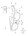
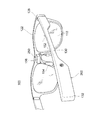
実施形態では、生体信号として眼電位信号を例にし、理論的に同様の信号を測定可能な電極の位置としては、メガネに設けられる一対のノーズパッドを例にする。図1は、実施例におけるメガネ100の前方からの一例を示す斜視図である。図2は、実施例におけるメガネ100の後方からの一例を示す斜視図である。メガネ100は、レンズ110及びフレーム120を備える。メガネ100及びフレーム120は、アイウエアの一例である。
[Embodiment]
In the embodiment, an electrooculogram signal is taken as an example of a biological signal, and a pair of nose pads provided on the glasses is taken as an example of a position of an electrode that can theoretically measure a similar signal. FIG. 1 is a perspective view illustrating an example from the front of the
フレーム120は、一対のレンズ110を支持する。フレーム120は、リム122と、眉間部(例えばブリッジ)124と、ヨロイ126と、丁番128と、テンプル130と、モダン132と、一対のノーズパッド(鼻パッド)140と、電線(不図示)と、処理装置200と、増幅部250とを有する。なお、メガネ100の種類によっては、一枚レンズを用いることでフレームのブリッジ部分がない場合がある。この場合、一枚レンズの眉間部分を眉間部とする。
The
リム122は、レンズ110を保持し、前面及び後面を有する。後面は、テンプル130を折り畳む側の面であり、前面は、後面に対向する面である。ヨロイ126は、リム122の外側に設けられ、丁番128によりテンプル130を回転可能に保持する。テンプル130は、使用者の耳の上部を押圧して、この部位を挟持する。モダン132は、テンプル130の先端に設けられる。モダン132は、使用者の耳の上部に接触する。リム122、ヨロイ126、丁番128、テンプル130、及びモダン132は、それぞれ左右一対に設けられる。なお、モダン132は、必ずしもメガネ100に設ける必要はない。
The
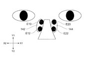
一対のノーズパッド140は、右ノーズパッド142及び左ノーズパッド144を含む。右ノーズパッド142は、第1電極E10及び第2電極E12を含み、左ノーズパッド144は、第3電極E20及び第4電極E22を含む。
The pair of
第1電極E10及び第2電極E12は、使用者の右眼の眼電位を検出する。第3電極E20及び第4電極E22は、使用者の左眼の眼電位を検出する。このように、眼電位を検出するための電極を、使用者の皮膚に必然的に接触するノーズパッドの表面に設ける。これにより、使用者の眼の周囲に二対の電極を接触させるのに比べて、使用者の皮膚に与える負担を軽減することができる。 The first electrode E10 and the second electrode E12 detect the electrooculogram of the user's right eye. The third electrode E20 and the fourth electrode E22 detect the electrooculogram of the user's left eye. As described above, the electrode for detecting the electrooculogram is provided on the surface of the nose pad that inevitably contacts the skin of the user. Thereby, the burden given to a user's skin can be reduced compared with making a pair of electrodes contact the circumference | surroundings of a user's eye.
実施形態においては、例えば、第1電極E10及び第3電極E20を接地電極(グランド)とする。また、接地電極により検知される値は、ほぼゼロである。眼電位の検出目的に応じて、第1電極E10の第1電位と第2電極E12の第2電位との差分値を用いたり、平均値を用いたりする。第3電極E20及び第4電極E22についても、第1電極E10及び第2電極E12に関して用いる信号と同様である。 In the embodiment, for example, the first electrode E10 and the third electrode E20 are ground electrodes (ground). The value detected by the ground electrode is almost zero. A difference value between the first potential of the first electrode E10 and the second potential of the second electrode E12 or an average value is used according to the purpose of detecting the ocular potential. The signals for the third electrode E20 and the fourth electrode E22 are the same as those used for the first electrode E10 and the second electrode E12.
処理装置200は、例えば、テンプル130に設けてもよい。これにより、メガネ100を正面から見たときのデザイン性を損なうことがない。処理装置200の設置位置は、必ずしもテンプル130である必要はないが、メガネ100を装着した際のバランスを考慮して位置決めすればよい。処理装置200は、電線を介して増幅部250に接続される。なお、処理装置200と、増幅部250とは、無線を介して接続されてもよい。
The
増幅部250は、第1電極E10及び第2電極E12、並びに第3電極E20及び第4電極E22の近傍(例えば眉間部)に設けられ、増幅対象の各電極と電線を介して接続される。増幅部250は、各電極が検出した眼電位を示す眼電位信号を取得する。例えば、増幅部250は、第1電極E10及び第2電極E12、並びに第3電極E20及び第4電極E22により検出された眼電位を示す眼電位信号を増幅する。また、増幅部250は、第1電極E10による眼電位信号(第1信号)と第2電極E12による眼電位信号(第2信号)の差分を示す第1差分信号を増幅してもよい。同様に、増幅部250は、第3電極E20による眼電位信号(第3信号)と第4電極E22による眼電位信号(第4信号)の差分を示す第2差分信号を増幅してもよい。
The amplifying
また、増幅部250は、眼電位信号を演算する処理部を有していれば、増幅する前又は増幅した後の各眼電位信号のサンプリング値に対する、上述した差分値又は平均値を求めるための加減処理を行ってもよい。増幅部250により増幅された信号又は処理された信号は、処理装置200に出力される。
In addition, if the
外部装置300は、通信機能を有する情報処理装置である。例えば、外部装置300は、使用者が所持する携帯電話及びスマートフォン等の携帯通信端末やパーソナルコンピュータ等である。外部装置300は、図3に示す送信部204から受信した眼電位に関する信号に基づく処理を実行する。例えば、外部装置300は、受信した眼電位に関する信号から、瞬目や視線移動を検出する。
The
<処理装置200の構成>
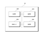
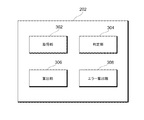
図3は、実施例における処理装置200の構成の一例を示すブロック図である。図3に示すように、処理装置200は、処理部202、送信部204、6軸センサ206、及び電源部208を有する。また、第1電極E10及び第2電極E12、並びに第3電極E20及び第4電極E22は、例えば増幅部を介して電線を用いて処理部202に接続される。なお、処理装置200の各部は、一方のテンプルに設けられるのではなく、一対のテンプルに分散して設けられてもよい。6軸センサ206は、必ずしも設けられなくてもよい。
<Configuration of
FIG. 3 is a block diagram illustrating an example of the configuration of the
6軸センサ206は、3軸加速度センサ及び3軸角速度センサである。また、これらの各センサは別個に設けられてもよい。6軸センサ206は、検出したセンサ信号(又は検出データとも称す)を処理部202に出力する。
The 6-
処理部202は、例えばプロセッサやメモリを含み、増幅部250から増幅された眼電位信号を取得し、処理する。例えば、処理部202は、第1電極E10を基準とした第2電極E12の電位を示す基準眼電位信号(例えば第1差分信号)を処理してもよい。また、処理部202は、第3電極E20を基準とした第4電極E22の電位を示す基準眼電位信号(例えば第2差分信号)を処理してもよい。
The
このとき、処理部202は、右眼及び左眼において、各電極から検出された眼電位に基づいて、眼の垂直方向及び/又は水平方向の動きを示す信号となるように処理を行ってもよい。
At this time, the
送信部204は、処理部202によって処理された各信号を外部装置300に送信する。例えば、送信部204は、Bluetooth(登録商標)及び無線LAN等の無線通信、又は有線通信によって各信号を外部装置300に送信する。電源部208は、処理部202、送信部204、6軸センサ206等に電力を供給する。
The
ここで、上述した眼電位信号に関する処理は、各電極が鼻に適切に接触していることを前提としている。しかし、アイウエア100の装着具合によって、1以上の電極が鼻に非接触又は接触不良となっていることがある。特に、接地電極とする上端部の第1電極E10又は第3電極E20が非接触又は接触不良となると、適切な眼電位信号が取得できない。そこで、上端部の電極の一部が鼻と非接触又は接触不良であっても、適切に眼電位を取得することが可能な実施例1及び実施例2に関する構成について、以下説明する。
Here, the processing relating to the electrooculogram signal described above is based on the premise that each electrode is in proper contact with the nose. However, depending on how the
<実施例1>
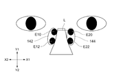
実施例1では、物理的な構成を用いることにより、上端部の電極の一部が鼻と非接触又は接触不良であっても、適切に眼電位を取得することができる。図4は、実施例1におけるノーズパッド142及び144に関する構成例を示す図である。図4に示す例では、簡単のため、ノーズパッドや電極のみを用いてアイウエアを表現する。
<Example 1>
In the first embodiment, by using a physical configuration, it is possible to appropriately acquire an electrooculogram even if a part of the electrode at the upper end portion is not in contact with the nose or in poor contact. FIG. 4 is a diagram illustrating a configuration example regarding the
図4に示す例では、アイウエア100の装着時のノーズパッド142及び144が示される。図4に示すように、例えば、右ノーズパッド142の表面に、上端部の第1電極E10、下端部の第2電極E12が設けられ、左ノーズパッド144の表面に、上端部の第3電極E20、下端部の第4電極E22が設けられる。
In the example shown in FIG. 4,
このとき、接地電極となる上端部の電極のうち、少なくとも1つが鼻に接触しない、又は接触不良になると、非接触/接触不良の眼電位信号を適切に取得することができない。そのため、実施例1では、鼻に接触しない又は接触不良の可能性がある上端部の電極同士を結線(電気的に接続)することで、鼻に接触している側の電極の電位を、両上端部の電極の基準電位として共通で用いることができる構成を採用する。例えば、上端部の第1電極E10及び第3電極E20を結線する部材Lが設けられる。部材Lは、金属の電線等である。また、部材Lは、ノーズパッドやフレーム内を通すことで、外部に視認できないようにするとよい。 At this time, if at least one of the electrodes at the upper end serving as the ground electrode does not come into contact with the nose or has poor contact, an electrooculogram signal of non-contact / non-contact cannot be appropriately acquired. Therefore, in Example 1, the electrodes on the side in contact with the nose are connected to each other by connecting (electrically connecting) the electrodes at the upper end portions that do not contact the nose or may have poor contact. A configuration that can be used in common as the reference potential of the upper end electrode is employed. For example, a member L for connecting the first electrode E10 and the third electrode E20 at the upper end is provided. The member L is a metal electric wire or the like. Moreover, the member L is good not to visually recognize outside by letting a nose pad or a frame pass.
これにより、上端部の第1電極E10及び第3電極E20が導通しているため、一方が適切に鼻に接触していれば、それを基準電位として、処理部202は、両上端部の電極で共通して基準電位を用いることができる。
Thereby, since the first electrode E10 and the third electrode E20 at the upper end are conductive, if one of them is in proper contact with the nose, the
また、第1電極E10及び第3電極E20を用いて導通させることで、接触対象の鼻に対して2つの方向から接触を図ることができ、少なくともいずれか一方で適切に鼻に接触させる可能性を高めることができる。 Further, by conducting using the first electrode E10 and the third electrode E20, contact with the nose to be contacted can be achieved from two directions, and at least one of them may be appropriately brought into contact with the nose. Can be increased.
以上、実施例1によれば、第1電極E10及び第3電極E20が導通しているため、いずれか一方の電極が適切に接触されれば、適切な眼電位信号を取得することができるようになる。 As described above, according to the first embodiment, since the first electrode E10 and the third electrode E20 are conductive, it is possible to acquire an appropriate electrooculogram signal if any one of the electrodes is appropriately contacted. become.
<実施例2>
実施例2では、ソフトウェアを用いることにより、上端部の電極が鼻と非接触又は接触不良であっても、眼電位を適切に取得することができる。図5は、実施例2におけるノーズパッド142及び144に関する構成例を示す図である。なお、実施例2の物理的な構成は、実施例1の結線用の部材Lがない構成と同じである。
<Example 2>
In the second embodiment, by using software, the electrooculogram can be appropriately acquired even if the electrode at the upper end is not in contact with the nose or is in poor contact. FIG. 5 is a diagram illustrating a configuration example regarding the
実施例2では、処理装置20の処理部202において、グランドとして不適切な信号を判定し、その信号を適切な信号値に置き換える。例えば、処理部202は、所定範囲内(例えば絶対値が1μV以内)に含まれる信号を適切な信号とし、この所定範囲外の信号が有る場合、所定範囲外の信号を、所定範囲内の信号に置き換える。
In the second embodiment, the
上記処理を実行するため、処理部202は、グランド信号を適切化する機能を有する。図6は、処理部202の機能構成の一例を示す図である。図6に示す例では、処理部202は、取得部302、判定部304、算出部306、及びエラー処理部308を有する。
In order to execute the above processing, the
取得部302は、各電極から、第1電極E10に基づく第1信号、第2電極E12に基づく第2信号、第3電極E20に基づく第3信号、及び第4電極E22に基づく第4信号を取得する。
The
判定部304は、基準電位としての役割がある第1信号及び第3信号が、所定範囲内であるか否かを判定する。判定結果は、算出部306に出力される。
The
算出部306は、第1信号及び第3信号が所定範囲内であれば、第1信号と第2信号との差分を示す第1差分信号、並びに第3信号及び第4信号との差分を示す第2差分信号を算出する(式(1)及び(2)参照)。
第1差分信号=|第2信号−第1信号| ・・・式(1)
第2差分信号=|第4信号−第3信号| ・・・式(2)
When the first signal and the third signal are within a predetermined range, the
First difference signal = | second signal−first signal | Expression (1)
Second difference signal = | fourth signal−third signal | Expression (2)
また、算出部306は、第1信号及び第3信号のいずれか1つのみが所定範囲内であれば、第2信号及び第4信号それぞれと、所定範囲内の第1信号又は第3信号との差分を示す第1差分信号及び第2差分信号を算出する(式(3)及び(4)参照)。
第1差分信号=|第2信号−(第1信号及び第3信号のうち、所定範囲に入る信号)|
・・・式(3)
第2差分信号=|第4信号−(第1信号及び第3信号のうち、所定範囲に入る信号)|
・・・式(4)
In addition, when only one of the first signal and the third signal is within a predetermined range, the
First difference signal = | second signal− (a signal that falls within a predetermined range among the first signal and the third signal) |
... Formula (3)
Second difference signal = | fourth signal− (a signal that falls within a predetermined range among the first signal and the third signal) |
... Formula (4)
エラー処理部308は、第1信号及び第3信号が所定範囲外であれば、エラー処理を実行する。エラー処理は、外部装置300の表示画面にエラーを表示したり、音声等でエラーを通知したりすることで、ユーザに対してアイウエア100を装着し直しさせるように報知する処理である。これにより、ユーザに対して、アイウエアの100を装着し直しさせて、処理部202は、その後に適切な眼電位信号を取得することができるようになる。 なお、第1信号及び第3信号が所定範囲外の場合、エラー処理部308による処理ではなく、算出部206により、所定範囲内の予め設定された信号値を用いて、各差分信号を算出するようにしてもよい。
The
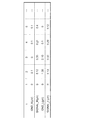
図7は、各電極により取得される信号値の一例を示す図である。図7に示すGND_Rは、第1電極E10により取得される第1信号であり、SIGNAL_Rは、第2電極E12により取得される第2信号であり、GND_Lは、第3電極E20により取得される第3信号であり、SIGNAL_Lは、第4電極E22により取得される第4信号である。これらの信号値は、取得部302により取得される。
FIG. 7 is a diagram illustrating an example of signal values acquired by each electrode. In FIG. 7, GND_R is a first signal acquired by the first electrode E10, SIGNAL_R is a second signal acquired by the second electrode E12, and GND_L is acquired by the third electrode E20. SIGNAL_L is a fourth signal acquired by the fourth electrode E22. These signal values are acquired by the
ここで、判定部304は、GND_RとGND_Lが、所定範囲内(絶対値が1μV以内)に入るか否かを判定する。例えば、両信号とも所定範囲内であるt=4の時点では、算出部306は、第1差分信号(0.11=0.21−0.1)、第2差分信号(0.19=0.29−0.1)を算出する。
Here, the
また、t=3の時点では、GND_L(=2.10)が所定範囲外となる。よって、差算出部306は、GND_Lとして、又はGND_Lの代わりに、所定範囲内のGND_R(0μV)を用いて、第1差分信号(0.35=0.35−0)、第2差分信号(0.33=0.33−0)を算出する。
Further, at the time point t = 3, GND_L (= 2.10) is outside the predetermined range. Therefore, the
これにより、接地電極となる電極に接触不良があっても、他の接地電極で取得された眼電位信号を用いることで、適切な眼電位信号を取得することができるようになる。 Thereby, even if there is a contact failure in the electrode to be the ground electrode, an appropriate electrooculogram signal can be acquired by using an electrooculogram signal acquired by another ground electrode.
<動作>
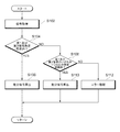
次に、実施例2における処理部202の動作について説明する。図8は、実施例2における処理部202の処理の一例を示すフローチャートである。図8に示すステップS102で、取得部302は、各電極に基づく信号(第1〜第4信号)を取得する。
<Operation>
Next, the operation of the
ステップS104で、判定部304は、第1信号及び第3信号が、所定範囲内であるか否かを判定する。判定結果が肯定であれば(ステップS104−YES)、処理はステップS106に進み、判定結果が否定であれば(ステップS104−NO)、処理はステップS108に進む。
In step S104, the
ステップS106で、算出部306は、第1信号と第2信号との差分を示す第1差分信号、及び第3信号及び第4信号との差分を示す第2差分信号を算出する(例えば式(1)及び(2)参照)。
In step S106, the
ステップS108で、判定部304は、第1信号及び第3信号のいずれか1つのみが、所定範囲内であるか否かを判定する。判定結果が肯定であれば(ステップS108−YES)、処理はステップS110に進み、判定結果が否定であれば(ステップS108−NO)、処理はステップS112に進む。
In step S108, the
ステップS110で、算出部306は、第2信号及び第4信号それぞれと、所定範囲内の第1信号又は第3信号との差分を示す第1差分信号及び第2差分信号を算出する(例えば式(3)及び(4)参照)。
In step S110, the
ステップS112で、エラー処理部308は、エラー処理を実行する。ステップS106、S110、及びS112の後は、処理はステップS102に戻る。また、ステップS106及びS110で算出された第1差分信号及び第2差分信号は、送信部204を介して外部装置300に出力される。
In step S112, the
なお、図8で説明した処理のフローに含まれる各処理ステップは、処理内容に矛盾が生じない範囲で、任意に順番を変更して又は並列に実行することができるとともに、各処理ステップ間に他のステップを追加してもよい。また、便宜上1ステップとして記載されているステップは、複数ステップに分けて実行することができる一方、便宜上複数ステップに分けて記載されているものは、1ステップとして把握することができる。 Note that each processing step included in the processing flow described in FIG. 8 can be executed in any order or in parallel as long as there is no contradiction in processing contents, and between the processing steps. Other steps may be added. Further, a step described as one step for convenience can be executed by being divided into a plurality of steps, while a step described as being divided into a plurality of steps for convenience can be grasped as one step.
以上、実施例2によれば、ソフトウェアによる処理を用いて、ノーズパッドに複数の電極が設けられる際、1つの電極が適切に接触していなくても、眼電位信号を適切に取得することができる。 As described above, according to the second embodiment, when a plurality of electrodes are provided on the nose pad using software processing, an electrooculogram signal can be appropriately acquired even if one electrode is not in proper contact. it can.
以上、本発明について実施例を用いて説明したが、本発明の技術的範囲は上記実施例に記載の範囲には限定されない。上記実施例に、多様な変更又は改良を加えることが可能であることが当業者に明らかである。その様な変更又は改良を加えた形態も本発明の技術的範囲に含まれ得ることが、特許請求の範囲の記載から明らかである。 As mentioned above, although this invention was demonstrated using the Example, the technical scope of this invention is not limited to the range as described in the said Example. It will be apparent to those skilled in the art that various modifications and improvements can be made to the above-described embodiments. It is apparent from the description of the scope of claims that embodiments with such changes or improvements can be included in the technical scope of the present invention.
100 メガネ
120 フレーム
124 眉間部
140 ノーズパッド
E10 第1電極
E12 第2電極
E20 第3電極
E22 第4電極
L 結線部材
100
Claims (7)
前記フレームに接続される一対のノーズパッドであって、それぞれの上端部及び下端部に電極を有する一対のノーズパッドと、
前記一対のノーズパッドの前記上端部の電極同士を電気的に接続する部材と、
を有するアイウエア。 Frame,
A pair of nose pads connected to the frame, each having a pair of nose pads having electrodes at their upper and lower ends; and
A member for electrically connecting the electrodes at the upper ends of the pair of nose pads;
Having eyewear.
前記第1信号及び前記第3信号が、所定範囲内であるか否かを判定し、
前記第1信号及び前記第3信号が前記所定範囲内であれば、前記第1信号と前記第2信号との差分を示す第1差分信号、及び前記第3信号と前記第4信号との差分を示す第2差分信号を算出し、
前記第1信号及び前記第3信号のいずれか1つのみが前記所定範囲内であれば、前記第2信号及び前記第4信号それぞれと、前記所定範囲内の前記第1信号又は前記第3信号との差分を示す第1差分信号及び第2差分信号を算出し、
前記第1差分信号及び前記第2差分信号を出力する、処理をコンピュータが実行する情報処理方法。 From the first electrode at the upper end and the second electrode at the lower end provided on the right nose pad, and from the third electrode at the upper end and the fourth electrode at the lower end provided on the left nose pad, the first electrode A first signal based on, a second signal based on the second electrode, a third signal based on the third electrode, and a fourth signal based on the fourth electrode,
Determining whether the first signal and the third signal are within a predetermined range;
If the first signal and the third signal are within the predetermined range, a first difference signal indicating a difference between the first signal and the second signal, and a difference between the third signal and the fourth signal Calculating a second differential signal indicating
If only one of the first signal and the third signal is within the predetermined range, the second signal and the fourth signal respectively, and the first signal or the third signal within the predetermined range. Calculating a first difference signal and a second difference signal indicating the difference between
An information processing method in which a computer executes a process of outputting the first differential signal and the second differential signal.
前記第1信号及び前記第3信号が、所定範囲内であるか否かを判定し、
前記第1信号及び前記第3信号が前記所定範囲内であれば、前記第1信号と前記第2信号との差分を示す第1差分信号、及び前記第3信号と前記第4信号との差分を示す第2差分信号を算出し、
前記第1信号及び前記第3信号のいずれか1つのみが前記所定範囲内であれば、前記第2信号及び前記第4信号それぞれと、前記所定範囲内の前記第1信号又は前記第3信号との差分を示す第1差分信号及び第2差分信号を算出し、
前記第1差分信号及び前記第2差分信号を出力する、処理をコンピュータに実行させるプログラム。 From the first electrode at the upper end and the second electrode at the lower end provided on the right nose pad, and from the third electrode at the upper end and the fourth electrode at the lower end provided on the left nose pad, the first electrode A first signal based on, a second signal based on the second electrode, a third signal based on the third electrode, and a fourth signal based on the fourth electrode,
Determining whether the first signal and the third signal are within a predetermined range;
If the first signal and the third signal are within the predetermined range, a first difference signal indicating a difference between the first signal and the second signal, and a difference between the third signal and the fourth signal Calculating a second differential signal indicating
If only one of the first signal and the third signal is within the predetermined range, the second signal and the fourth signal respectively, and the first signal or the third signal within the predetermined range. Calculating a first difference signal and a second difference signal indicating the difference between
A program for causing a computer to execute processing for outputting the first differential signal and the second differential signal.
上端部の第3電極及び下端部の第4電極を有する左ノーズパッドと、
処理部と、を備えるアイウエアであって、
前記処理部は、
前記第1電極に基づく第1信号、前記第2電極に基づく第2信号、前記第3電極に基づく第3信号、及び前記第4電極に基づく第4信号を取得し、
前記第1信号及び前記第3信号が、所定範囲内であるか否かを判定し、
前記第1信号及び前記第3信号が前記所定範囲内であれば、前記第1信号と前記第2信号との差分を示す第1差分信号、及び前記第3信号と前記第4信号との差分を示す第2差分信号を算出し、
前記第1信号及び前記第3信号のいずれか1つのみが前記所定範囲内であれば、前記第2信号及び前記第4信号それぞれと、前記所定範囲内の前記第1信号又は前記第3信号との差分を示す第1差分信号及び第2差分信号を算出し、
前記第1差分信号及び前記第2差分信号を出力する、アイウエア。 A right nose pad having a first electrode at the upper end and a second electrode at the lower end;
A left nose pad having a third electrode at the upper end and a fourth electrode at the lower end;
An eyewear comprising a processing unit,
The processor is
Obtaining a first signal based on the first electrode, a second signal based on the second electrode, a third signal based on the third electrode, and a fourth signal based on the fourth electrode;
Determining whether the first signal and the third signal are within a predetermined range;
If the first signal and the third signal are within the predetermined range, a first difference signal indicating a difference between the first signal and the second signal, and a difference between the third signal and the fourth signal Calculating a second differential signal indicating
If only one of the first signal and the third signal is within the predetermined range, the second signal and the fourth signal respectively, and the first signal or the third signal within the predetermined range. Calculating a first difference signal and a second difference signal indicating the difference between
Eyewear for outputting the first differential signal and the second differential signal.
Priority Applications (1)
| Application Number | Priority Date | Filing Date | Title |
|---|---|---|---|
| JP2016084423A JP2017192548A (en) | 2016-04-20 | 2016-04-20 | Eyewear, information processing method, and program |
Applications Claiming Priority (1)
| Application Number | Priority Date | Filing Date | Title |
|---|---|---|---|
| JP2016084423A JP2017192548A (en) | 2016-04-20 | 2016-04-20 | Eyewear, information processing method, and program |
Publications (1)
| Publication Number | Publication Date |
|---|---|
| JP2017192548A true JP2017192548A (en) | 2017-10-26 |
Family
ID=60155110
Family Applications (1)
| Application Number | Title | Priority Date | Filing Date |
|---|---|---|---|
| JP2016084423A Pending JP2017192548A (en) | 2016-04-20 | 2016-04-20 | Eyewear, information processing method, and program |
Country Status (1)
| Country | Link |
|---|---|
| JP (1) | JP2017192548A (en) |
Cited By (1)
| Publication number | Priority date | Publication date | Assignee | Title |
|---|---|---|---|---|
| US11237411B2 (en) | 2018-12-03 | 2022-02-01 | Jins Holdings Inc. | Nose pad and eyewear |
-
2016
- 2016-04-20 JP JP2016084423A patent/JP2017192548A/en active Pending
Cited By (1)
| Publication number | Priority date | Publication date | Assignee | Title |
|---|---|---|---|---|
| US11237411B2 (en) | 2018-12-03 | 2022-02-01 | Jins Holdings Inc. | Nose pad and eyewear |
Similar Documents
| Publication | Publication Date | Title |
|---|---|---|
| CN104799855B (en) | Eyewear article | |
| EP3304243B1 (en) | Capacitive sensors for determining eye gaze direction | |
| KR20220087104A (en) | Wearable device and method for detecting motion gesture of the wearable device | |
| EP3067782B1 (en) | Information processing apparatus, control method, and program | |
| US20160070122A1 (en) | Computerized replacement temple for standard eyewear | |
| WO2015159862A1 (en) | Eyewear | |
| JP2015213734A (en) | Program, information processing apparatus, and eyewear | |
| CN110366388B (en) | Information processing method, information processing apparatus, and computer-readable storage medium | |
| JP6556860B2 (en) | Information processing method, information processing apparatus, program, and eyewear | |
| JP2017192548A (en) | Eyewear, information processing method, and program | |
| JP6656166B2 (en) | Program, information processing device, and eyewear | |
| JP6761273B2 (en) | Eyewear | |
| JP6687639B2 (en) | Information processing method, information processing device, program, and eyewear | |
| WO2015159851A1 (en) | Detection unit, eyewear, and ocular potential detection system | |
| JP2017227941A (en) | Program, information processing apparatus, and eyewear | |
| WO2017064800A1 (en) | Program, information processing device, and eyewear | |
| JP2015202199A (en) | Electrooculogram information processing apparatus, electrooculogram information processing system, wearing tool and program | |
| JP2018010329A (en) | Program, information processing device, and eyewear | |
| WO2017064799A1 (en) | Eyewear | |
| JP2018082727A (en) | Signal processing method, program, information processing equipment, and eye wear | |
| JP2015205030A (en) | Eyewear | |
| WO2016158574A1 (en) | Sight line movement detection method, program, information processing device, and eyewear | |
| US20240041351A1 (en) | Method for determining front-back and left-right directions of pose sensor worn on head of user | |
| JP2015202196A (en) | Eyewear | |
| JP2015202188A (en) | Eyewear |