JP2017191998A - Operating device, operating device control method, and program - Google Patents
Operating device, operating device control method, and program Download PDFInfo
- Publication number
- JP2017191998A JP2017191998A JP2016079738A JP2016079738A JP2017191998A JP 2017191998 A JP2017191998 A JP 2017191998A JP 2016079738 A JP2016079738 A JP 2016079738A JP 2016079738 A JP2016079738 A JP 2016079738A JP 2017191998 A JP2017191998 A JP 2017191998A
- Authority
- JP
- Japan
- Prior art keywords
- image data
- imaging
- imaging device
- received
- parameter
- Prior art date
- Legal status (The legal status is an assumption and is not a legal conclusion. Google has not performed a legal analysis and makes no representation as to the accuracy of the status listed.)
- Pending
Links
Images
Landscapes
- Exposure Control For Cameras (AREA)
- Lens Barrels (AREA)
- Studio Devices (AREA)
Abstract
Description
本発明は、撮像装置を操作可能な操作装置、操作装置の制御方法、及び、プログラム、並びに、撮像装置と撮像装置を操作可能な操作装置とを備える撮像システムに関する。 The present invention relates to an operating device capable of operating an imaging device, a control method for the operating device, a program, and an imaging system including an imaging device and an operating device capable of operating the imaging device.
従来から、撮像装置と撮像装置を操作する操作装置とを備える撮像システムが知られている。このような撮像システムでは、撮像装置と操作装置との間で、操作命令と画像データとが伝達されて、操作装置により撮像装置を操作できる。すなわち、撮像装置は撮影した画像データを操作装置に送信する。操作装置は、受信した画像データをユーザに提示しながら、ユーザからの撮像装置に対する操作情報を受け付けて、操作命令を撮像装置に送信する(例えば特許文献1)。 2. Description of the Related Art Conventionally, an imaging system including an imaging device and an operation device that operates the imaging device is known. In such an imaging system, an operation command and image data are transmitted between the imaging device and the operating device, and the imaging device can be operated by the operating device. That is, the imaging device transmits the captured image data to the operation device. While presenting the received image data to the user, the operation device receives operation information for the imaging device from the user and transmits an operation command to the imaging device (for example, Patent Document 1).
しかしながら、このような撮影システムにおいては、例えば撮像装置と操作装置との間の通信の回線速度、及び、伝送するデータ量に応じて、操作装置と撮像装置との間に通信の遅延(通信ディレイ)が生じることがある。このような通信ディレイが生じると、ユーザが操作装置に表示される画像データを見ながら撮像装置に対する操作を操作装置に入力したとき、入力した操作結果が反映された画像データが操作装置に表示されるまでに、撮像装置の撮影環境が変化することがある。例えばユーザが、操作装置に表示される画像データを参照しながら撮像装置に対するズーム操作を操作装置に入力すると、ズーム量等の操作量が大きすぎたり小さすぎたりすることがある。このため、ユーザが意図した操作を行うことが困難になることがある。 However, in such an imaging system, a communication delay (communication delay) between the operating device and the imaging device, for example, depending on the line speed of the communication between the imaging device and the operating device and the amount of data to be transmitted. ) May occur. When such a communication delay occurs, when the user inputs an operation on the imaging device to the operation device while viewing the image data displayed on the operation device, the image data reflecting the input operation result is displayed on the operation device. Until then, the shooting environment of the imaging device may change. For example, when a user inputs a zoom operation on the imaging device to the operation device while referring to image data displayed on the operation device, an operation amount such as a zoom amount may be too large or too small. For this reason, it may be difficult to perform an operation intended by the user.
本発明は上記のような点に鑑みてなされたものであり、通信ディレイの影響によるユーザ操作のずれを低減することを目的とする。 The present invention has been made in view of the above points, and an object of the present invention is to reduce a shift in a user operation due to an influence of a communication delay.
本発明の操作装置は、撮像装置を操作可能な操作装置であって、前記撮像装置に対する操作を受け付ける受付手段と、前記撮像装置から受信した画像データを、前記受付手段で受け付けた前記操作に基づいて補正して補正画像データを生成する補正手段と、前記補正画像データを表示する表示手段と、を備えることを特徴とする。 The operating device according to the present invention is an operating device capable of operating the imaging device, the receiving unit receiving an operation on the imaging device, and the image data received from the imaging device based on the operation received by the receiving unit. Correction means for generating corrected image data by correction, and display means for displaying the corrected image data.
本発明によれば、通信ディレイの影響によるユーザ操作のずれを低減することができる。 ADVANTAGE OF THE INVENTION According to this invention, the shift | offset | difference of user operation by the influence of a communication delay can be reduced.
<第1実施形態>
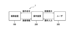
まず、図1を参照して、本実施形態の撮像システム1について説明する。図1は、撮像システム1の構成図である。
撮像システム1は、撮像装置100と操作装置200とを備える。
撮像装置100は、例えば所定の間隔で、ネットワーク通信により、画像情報を操作装置200に送信する。画像情報には、撮像装置100が撮影した画像データ、及び、撮影時の撮像装置100の状態の情報であるカメラ状態情報が含まれる。カメラ状態情報には、カメラパラメータが含まれる。カメラパラメータは、撮像装置100の主に撮影に関するパラメータであり、例えば、ズーム、フォーカス及び露出のパラメータがある。1つの画像情報に含まれる画像データとカメラ状態情報とは互いに対応する関係にある。なお、カメラパラメータは、撮像パラメータの一例である。
<First Embodiment>
First, the imaging system 1 of the present embodiment will be described with reference to FIG. FIG. 1 is a configuration diagram of the imaging system 1.
The imaging system 1 includes an
The
また、撮像装置100は、操作装置200からネットワーク通信により受信した操作命令に基づいて、操作命令に対応する処理を実行する。
なお、撮像装置100は、例えば所定の間隔で、画像データのみを操作装置200に送信し、操作装置200からの要求があったときにカメラ状態情報を操作装置200に送信するようにしてもよい。
In addition, the
Note that the
操作装置200は、例えばネットワーク通信により遠隔から撮像装置100を操作可能であり、撮像装置100から画像情報を受信し、画像情報に含まれる画像データを表示する。また、操作装置200は、ユーザ300による撮像装置100に対する操作を受け付け、受け付けた操作に対応する操作命令を撮像装置100に送信する。
ユーザ300は、操作装置200に表示される撮像装置100からの画像データを参照しながら、撮像装置100に対する操作を操作装置200に入力して、撮像装置100を操作できる。
The
The
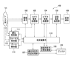
次に、図2を参照して、撮像装置100について説明する。図2は、撮像装置100のブロック図である。
レンズ群101は、1個以上のレンズ、絞りや減光フィルタにより露出を制御する機構、及び、フォーカスやズーム動作を制御する機構を備える。被写体からの光学像は、レンズ群101のレンズを経て、撮像素子102上に結像する。
撮像素子102は、撮像素子102上に結像した光学像を電気信号に変換して、カメラ信号処理部103に出力する。この際、撮像素子102の蓄積時間の制御により輝度補正が行われる。なお、撮像素子102がカメラ信号処理部103に出力する信号をカメラ信号と呼ぶ。
Next, the
The
The
カメラ信号処理部103は、撮像素子102から得られたカメラ信号に対し、ゲイン補正等の輝度補正、ホワイトバランス補正等の色補正、その他の信号処理等を行った上で、ビデオ信号処理部104に対して処理されたカメラ信号を出力する。
ビデオ信号処理部104は、カメラ信号処理部103から得られたカメラ信号に対して符号化処理を施し、記録再生処理部105に出力する。また、ビデオ信号処理部104は、符号化処理が施されたカメラ信号に対して、この信号に関する情報を付加した上で通信用信号送信処理部108に出力する。
記録再生処理部105は、符号化処理が施されたカメラ信号を記録に適した形態に変換して、記録媒体106に記録する。
The camera
The video
The recording /
記録媒体106は、画像データ等を記録する。記録媒体106は、制御演算部110が実行するプログラムを記録してもよい。なお、制御演算部110が実行するプログラムは、不図示のROM等に記録されていてもよい。
通信用信号受信処理部107は、アンテナ109が受信したデータを撮像装置100の内部で使われる形式又は形態に変換し制御演算部110に送る。
通信用信号送信処理部108は、アンテナ109で送信するデータをアンテナ109で送信できる形式又は形態に変換して、アンテナ109に送る。アンテナ109で送信するデータには、例えば、カメラパラメータを含む上記の画像情報がある。カメラパラメータであるズーム、フォーカス及び露出のパラメータは、それぞれ例えば、ズーム制御部113、フォーカス制御部112、及び、露出制御部111から取得できる。
The
The communication signal
The communication signal
アンテナ109は、撮像装置100とは別の装置である操作装置200等から送信されたデータを受信する。
制御演算部110は、撮像装置100を構成する各部の動作の制御、及び、各種の演算を行う。例えば、制御演算部110は、通信用信号受信処理部107からの情報や、露出制御部111、フォーカス制御部112、ズーム制御部113を含む各ブロックからの情報を読み取り、これらの情報を基に各ブロックの動作を制御する。
The
The
露出制御部111は、レンズ群101に対する露出の制御を行う。露出の制御は、撮像素子102からのカメラ信号、カメラ信号処理部103からのカメラ信号、及び、制御演算部110からの制御の少なくともいずれかに基づいて行われる。
フォーカス制御部112は、レンズ群101に対するフォーカスの制御を行う。フォーカスの制御は、制御演算部110からの制御に基づいて行われる。
ズーム制御部113は、レンズ群101に対するズームの制御を行う。ズームの制御は、制御演算部110からの制御に基づいて行われる。
The
The
The
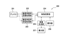
次に、図3を参照して、操作装置200について説明する。図3は、操作装置200のブロック図である。
アンテナ201は、操作装置200とは別の装置である撮像装置100等から送信されたデータを受信する。アンテナ201は、例えば画像情報を受信し、受信した画像情報を通信用信号受信処理部203に対して出力する。また、アンテナ201は、操作命令等を撮像装置100等に送信する。
Next, the
The
通信用信号送信処理部202は、アンテナ201で送信するデータをアンテナ201で送信できる形式又は形態に変換して、アンテナ201に送る。
通信用信号受信処理部203は、受信した画像情報を制御演算部204へ送るとともに、制御演算部204を通じて画像生成部205へ送る。
制御演算部204は、操作装置200を構成する各部の動作の制御、及び、各種の演算を行う。制御演算部204は、例えば、ユーザ300から受け付けた撮像装置100に対する操作の情報、操作装置200から受信した画像データ、及び、その他の情報を基に、撮像装置100に対する操作命令を生成して、通信用信号送信処理部202に送る。
The communication signal
The communication signal
The
画像生成部205は、制御演算部204を介して操作部206から取得した撮像装置100に対する操作の情報、及び、撮像装置100から受信した画像データに基づいて、受信した画像データに対する補正を行い、補正画像データを生成する。そして、画像生成部205は、補正画像データを表示部207に送る。ユーザ300が撮像装置100に対する操作を行っていないときは、撮像装置100から受信した画像データを補正せずに、表示部207に送る。また、画像生成部205は、ユーザ300が撮像装置100に対する操作を行うためのGUI等を生成する。
The image generation unit 205 corrects the received image data based on the operation information for the
操作部206は、ユーザ300からの操作を受け付け、その情報を制御演算部204へ送る。操作部206は、ユーザ300からの操作装置200自体に対する操作の他に、ユーザからの撮像装置100に対する操作を受け付けることができる。ユーザ300からの撮像装置100に対する操作には、例えば、ズームの操作、フォーカスの操作、露出補正の操作、カラーバランス補正の操作がある。
表示部207は、画像生成部205から送られる画像データをユーザ300に表示する。
The
The
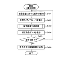
次に、図4を参照して、操作装置200における操作処理について説明する。図4は、操作装置200における操作処理のフローチャートである。なお、図4では、ユーザ300は撮像装置100に対する露出の操作を行う場合を例として説明する。
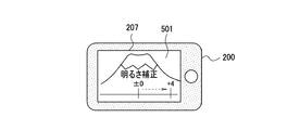
ユーザ300は、予め操作画面501を操作装置200に表示させて、操作装置200に操作処理を開始させる。図5に操作画面501の例を示す。操作画面501は、操作装置200の表示部207に表示される画面であり、ユーザ300は、操作画面501を操作することで、撮像装置100に対する操作を入力できる。図5は、撮像装置100に対する露出の操作を行うための操作画面501の例である。
操作画面501には、撮像装置100が撮影した画像データが表示される。ユーザ300は、この画像データを参照しながら、操作画面501を操作して露出の量を入力できる。なお、操作画面501に表示される画像データは、操作画面501が撮像装置100から、例えば所定の間隔で受信するものである。以下では、操作画面501でユーザ300が入力した露出の量等の、撮像装置100の操作に関する量を操作量と呼ぶ。
Next, with reference to FIG. 4, an operation process in the
The
On the
ステップS401において、操作装置200の操作部206は、ユーザ300からの撮像装置100に対する操作を受け付ける。ここで、操作部206は、ユーザ300からの撮像装置100に対する操作の種類と操作量とを受け付ける。なお、ステップS401は、受付手段による処理の一例である。
ステップS402において、操作装置200の制御演算部204は、ステップS401で入力された操作量から目標カメラパラメータを算出する。目標カメラパラメータは、ステップS401で受け付けた撮像装置100に対する操作の種類と操作量とに対応するカメラパラメータである。なお、目標カメラパラメータは、目標パラメータの一例である。
ステップS403において、操作装置200の画像生成部205は、補正画像生成処理を行う。補正画像生成処理では、操作装置200が撮像装置100から受信した画像データ、及び、撮像装置100に対する操作の種類と操作量とに基づいて、補正画像データが生成される。補正画像データは、操作装置200が撮像装置100から例えば直近に受信した画像データに対して、ステップS402で算出された目標カメラパラメータが反映された画像データである。補正画像生成処理の詳細は後に説明する。
In step S <b> 401, the
In step S402, the
In step S403, the image generation unit 205 of the
ステップS404において、操作装置200の表示部207は、ステップS403の補正画像生成処理で生成された補正画像データを表示する。
ユーザ300は、ステップS404で表示される操作画面501を参照して、撮像装置100に対する操作を続行するか終了するか判断し、判断結果に応じて操作部206に対して所定の操作を行う。撮像装置100に対する操作を終了するときに行う操作部206に対する操作は、撮像装置100への操作命令の送信指示である。
In step S404, the
The
ステップS405において、制御演算部204は、操作部206に対するユーザ300の操作に基づいて、ユーザ300が撮像装置100に対する操作の終了を指示したか否かを判断する。制御演算部204は、ユーザ300が撮像装置100に対する操作の終了を指示したとき処理をステップS406に進め、指示していないとき処理をステップS401に戻す。なお、制御演算部204は、操作部206が一定時間操作されなかったとき、ユーザ300は撮像装置100に対する操作の終了の指示をした、と判断してもよい。このとき、操作部206が一定時間操作されなかったことが、撮像装置100への操作命令の送信指示となる。
In step S <b> 405, based on the operation of the
ステップS406において、制御演算部204は、撮像装置100に対する操作命令を、通信用信号送信処理部202及びアンテナ201を介して、撮像装置100に送信する。撮像装置100に対する操作命令は、ユーザ300が入力した撮像装置100に対する操作、及び、ステップS402で算出した目標カメラパラメータの少なくともいずれかに基づいて生成される。
In step S <b> 406, the
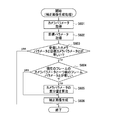
次に、図6を参照して、補正画像生成処理について説明する。図6は、操作装置200における補正画像生成処理のフローチャートである。上記のように、操作装置200は、例えば所定の間隔で撮像装置100から画像情報を受信しているものとする。
ステップS601において、操作装置200の制御演算部204は、撮像装置100から直近に受信した画像情報に含まれるカメラ状態情報を画像生成部205に送る。これにより、操作装置200の画像生成部205はカメラ状態情報に含まれるカメラパラメータを取得する。
ステップS602において、画像生成部205は、図4のステップS402で算出された目標カメラパラメータを取得する。
ステップS603において、画像生成部205は、ステップS602で取得した目標カメラパラメータと、ステップS601で取得したカメラ状態情報に含まれるカメラパラメータとを比較する。
Next, the corrected image generation process will be described with reference to FIG. FIG. 6 is a flowchart of the corrected image generation process in the
In step S <b> 601, the
In step S602, the image generation unit 205 acquires the target camera parameter calculated in step S402 of FIG.
In step S603, the image generation unit 205 compares the target camera parameter acquired in step S602 with the camera parameter included in the camera state information acquired in step S601.
画像生成部205は、両者が等しいとき、撮像装置100から直近に受信した画像データを、補正画像データとすることとして、図6に示す処理を終了する。これは、図4のステップS401で操作装置200が受け付けた撮像装置100に対する操作が、既に撮像装置100に対して反映されており、操作装置200は、撮像装置100に対する操作が反映された画像データを受信している、といえるためである。撮像装置100から受信した直近の画像データは、図4のステップS404で表示部207が表示する。
画像生成部205は、ステップS602で取得した目標カメラパラメータと、ステップS601で取得したカメラ状態情報に含まれるカメラパラメータとが異なるとき、処理をステップS604に進める。
なお、画像生成部205は、ステップS602で取得した目標カメラパラメータと、ステップS601で取得したカメラ状態情報に含まれるカメラパラメータとの差異が所定の範囲内のとき、両者が等しいと判断してもよい。
When the two are equal, the image generation unit 205 sets the image data received most recently from the
When the target camera parameter acquired in step S602 is different from the camera parameter included in the camera state information acquired in step S601, the image generation unit 205 advances the process to step S604.
Note that the image generation unit 205 determines that the target camera parameters acquired in step S602 and the camera parameters included in the camera state information acquired in step S601 are equal when the difference is within a predetermined range. Good.
ステップS604において、画像生成部205は、現在のフレームで受信したカメラパラメータと、一つ前のフレームで受信したカメラパラメータとの比較を行う。現在のフレームは、撮像装置100から受信した直近の画像データであり、現在のフレームで受信したカメラパラメータは、この直近の画像データに対応するカメラ状態情報に含まれるカメラパラメータである。また、一つ前のフレームは、撮像装置100から受信した直近の画像データの一つ前に受信した画像データであり、一つ前のフレームで受信したカメラパラメータは、この一つ前の画像データに対応するカメラ状態情報に含まれるカメラパラメータである。
画像生成部205は、現在のフレームで受信したカメラパラメータと、一つ前のフレームで受信したカメラパラメータとが等しいとき、処理をステップS606に進め、異なるとき処理をステップS605に進める。
なお、画像生成部205は、現在のフレームで受信したカメラパラメータと、一つ前のフレームで受信したカメラパラメータとの差異が所定の範囲内のとき、両者が等しいと判断してもよい。
In step S604, the image generation unit 205 compares the camera parameter received in the current frame with the camera parameter received in the previous frame. The current frame is the latest image data received from the
The image generation unit 205 advances the process to step S606 when the camera parameter received in the current frame is equal to the camera parameter received in the previous frame, and advances the process to step S605 when they are different.
Note that the image generation unit 205 may determine that the difference between the camera parameter received in the current frame and the camera parameter received in the previous frame is equal to each other within a predetermined range.
ステップS605において、画像生成部205は、目標カメラパラメータと、現在のフレームで受信したカメラパラメータとの差分量を算出する。これは、現在のフレームと前のフレームのカメラパラメータが等しくなければ、操作命令の反映途中でカメラパラメータが変化している、又は、自動露出制御等の自動制御によってカメラパラメータが変化していると考えられるためである。なお、ステップS605で算出される差分量は、例えば制御演算部110が備える不図示のメモリ又は記録媒体106等に保存される。
In step S605, the image generation unit 205 calculates a difference amount between the target camera parameter and the camera parameter received in the current frame. This is because if the camera parameters of the current frame and the previous frame are not equal, the camera parameters are changing during the reflection of the operation command, or the camera parameters are changed by automatic control such as automatic exposure control. This is because it is considered. Note that the difference amount calculated in step S605 is stored in, for example, a memory (not shown) or the
ステップS606において、画像生成部205は、ステップS605で算出されたカメラパラメータの差分量、及び、現在のフレームの画像データに基づいて、補正画像データを生成する。
ステップS606で使用されるカメラパラメータの差分量は、直近に実行されたステップS605で算出された値である。例えば、現在のフレーム及び一つ前のフレームのカメラパラメータが異なるときは、現在のフレームのカメラパラメータを用いてステップS605で算出されたカメラパラメータの差分量がステップS606で使用される。また、現在のフレーム及び一つ前のフレームのカメラパラメータが等しく、一つ前のフレーム及び二つ前のフレームのカメラパラメータが異なるときは、次の差分量がステップS606で使用される。すなわち、一つ前のフレームのカメラパラメータを用いてステップS605で算出されたカメラパラメータの差分量がステップS606で使用される。
In step S606, the image generation unit 205 generates corrected image data based on the difference amount of the camera parameter calculated in step S605 and the image data of the current frame.
The camera parameter difference amount used in step S606 is the value calculated in step S605 executed most recently. For example, when the camera parameters of the current frame and the previous frame are different, the difference amount of the camera parameter calculated in step S605 using the camera parameter of the current frame is used in step S606. If the camera parameters of the current frame and the previous frame are equal and the camera parameters of the previous frame and the previous frame are different, the next difference amount is used in step S606. That is, the difference amount of the camera parameter calculated in step S605 using the camera parameter of the previous frame is used in step S606.
ステップS606において、画像生成部205は、使用するカメラパラメータの差分量に応じて、補正画像データの生成方法を変更する。
本実施形態では、ユーザ300は露出の操作を行う例について説明しているため、目標カメラパラメータは露出のパラメータである。例えば、目標カメラパラメータのうちの目標アイリス制御値がF値4.0であり、現在のフレームのアイリス制御値がF5.6であるとする。このとき、目標カメラパラメータと現在のフレームのカメラパラメータとの間にはアイリス制御値について1段分の差分量があるものとして、画像生成部205は、1段分の露出補正をかける画像生成方法により、補正画像データを生成する。
In step S606, the image generation unit 205 changes the generation method of the corrected image data according to the difference amount of the camera parameter to be used.
In the present embodiment, since an example in which the
そして、次のフレームでアイリス制御値がF5.2に変化した場合、目標カメラパラメータと、次のフレームのアイリス制御値との間には3/4段分の差分量がある。このため、画像生成部205は、画像生成方法を3/4段分の露出補正をかける画像生成方法に変更して、補正画像データを生成する。 When the iris control value changes to F5.2 in the next frame, there is a difference amount of 3/4 steps between the target camera parameter and the iris control value of the next frame. Therefore, the image generation unit 205 changes the image generation method to an image generation method for performing exposure correction for 3/4 steps, and generates corrected image data.
ここでは、露出のパラメータのうちの目標アイリス制御値の例について説明したが、シャッター速度制御値、減光フィルタ制御値、ゲイン制御値等の他の露出のカメラパラメータについても、同様の方法で、露出補正をかける画像生成方法を変更できる。
ステップS606で生成された補正画像データは表示部207に送られて、表示部207が表示する。
Here, an example of the target iris control value among the exposure parameters has been described, but other exposure camera parameters such as a shutter speed control value, a neutral density filter control value, and a gain control value are also used in the same manner. The image generation method for applying exposure compensation can be changed.
The corrected image data generated in step S606 is sent to the
以上説明したように、操作装置200は、撮像装置100から受信した画像データを、操作部206で受け付けた撮像装置100に対する操作に基づいて補正して表示する。したがって、操作装置200は、通信ディレイが生じる場合であっても、撮像装置100に対する操作が反映された画像を遅延なく表示することができる。
このため、通信ディレイの影響によるユーザ操作のずれが低減し、通信ディレイによる撮像装置100に対する操作の遅れをユーザ300に意識させることがない。また、ユーザ300は、撮像装置100に対する操作後の画像を常に閲覧しながら、操作装置200から撮像装置100に対する操作を行うことができる。また、ユーザ300は、撮像装置100が操作装置200からの操作命令を反映中であっても、画像の連続性を失うことなく、撮像装置100に対する操作の結果を常に閲覧できる。
As described above, the
For this reason, the shift of the user operation due to the influence of the communication delay is reduced, and the
また、操作装置200は、ユーザ300から撮像装置100に対する操作の終了の指示を受けたとき、撮像装置100に操作命令を送信する。したがって、ユーザ300が撮像装置100に対する操作を行うたびに操作命令が撮像装置100に送信される、ということがないため、通信量を削減できる。
また、操作装置200は、補正画像データを生成するときに使用するカメラパラメータの差分量には、現在のフレーム及び一つ前のフレームのカメラパラメータが等しいときは、以前に算出されたカメラパラメータの差分量が使われる。したがって、カメラパラメータの差分量を常に算出する必要がなく、操作装置200の処理負荷が軽減される。
Further, the
When the camera parameter difference amount used when generating the corrected image data is equal to the camera parameter of the current frame and the previous frame, the
本実施形態では、図4のステップS402において、ユーザ300が入力した操作量から操作装置200が目標カメラパラメータを算出する。しかし、目標カメラパラメータの算出は撮像装置100が行ってもよい。このとき、操作装置200は、ユーザ300が入力した操作量を撮像装置100に送信する。撮像装置100は、受信した操作量から目標カメラパラメータを算出して、操作装置200に送信する。また、操作装置200は、撮像装置100への操作命令に、操作命令に対応するカメラパラメータを含んだカメラ状態情報を用いてもよい。
In the present embodiment, in step S402 of FIG. 4, the
また、操作装置200は、図4のステップS404で表示部207が表示する補正画像データに対して、操作装置200の内部に記録できる形式に再エンコード処理を施して、操作装置200が備える不図示の記録媒体や記録装置等に記録して保存してもよい。
In addition, the
<第2実施形態>
第1実施形態では、ユーザ300が撮像装置100に対する露出の操作を行う場合の例を説明した。本実施形態では、ユーザ300が撮像装置100に対するズームの操作を行う場合の例について説明する。なお、本実施形態の撮像システム1は、第1実施形態の撮像システム1と、図6のステップS606における補正画像データの生成方法以外は同様であるため、ここでは、本実施形態のステップS606の補正画像データの生成方法について説明する。
Second Embodiment
In the first embodiment, an example in which the
ステップS606において、画像生成部205は、使用するカメラパラメータの差分量に応じて、補正画像データの生成方法を変更する。
本実施形態では目標カメラパラメータはズームのパラメータである。目標カメラパラメータのうちの目標ズーム制御値が倍率4.0倍であり、現在のフレームのズーム制御値が倍率2.0であるとする。このとき、目標カメラパラメータと現在のフレームのカメラパラメータとの間にはズーム制御値について2倍分の差分量がある。このため、画像生成部205は、2倍分の拡大補正をかける画像生成方法により、補正画像データを生成する。この画像生成方法により、画像データに対して2倍の拡大補正処理がかけられる。
In step S606, the image generation unit 205 changes the generation method of the corrected image data according to the difference amount of the camera parameter to be used.
In the present embodiment, the target camera parameter is a zoom parameter. It is assumed that the target zoom control value among the target camera parameters is a magnification of 4.0 times, and the zoom control value of the current frame is a magnification of 2.0. At this time, there is a difference amount equivalent to twice the zoom control value between the target camera parameter and the camera parameter of the current frame. For this reason, the image generation unit 205 generates corrected image data by an image generation method for performing enlargement correction for twice. With this image generation method, the image data is subjected to double enlargement correction processing.
そして、次のフレームでズーム制御値が3倍に変化した場合、目標カメラパラメータと、次のフレームの目標ズーム制御との間には1.333倍分の差分量がある。このため、画像生成部205は、画像生成方法を1.333倍分の拡大補正処理をかける画像生成方法に変更して、補正画像データを生成する。 When the zoom control value changes three times in the next frame, there is a difference amount of 1.333 times between the target camera parameter and the target zoom control of the next frame. For this reason, the image generation unit 205 changes the image generation method to an image generation method that performs an enlargement correction process for 1.333 times, and generates corrected image data.
次に、目標ズーム制御値が現在のフレームのズーム制御値より小さい場合について説明する。例えば、目標ズーム制御値が倍率2.0倍であり、現在のフレームのズーム制御値が倍率4.0であるとする。このとき、目標カメラパラメータと現在のフレームのカメラパラメータとの間にはズーム制御値について1/2倍分の差分量がある。このため、画像生成部205は、1/2倍分の縮小補正をかける画像生成方法により、補正画像データを生成する。この画像生成方法により、画像データに対して1/2倍の縮小補正処理がかけられる。この例では縮小処理を行うので、縮小前の画像サイズに対して縮小後の画素数が足りなくなるが、足りない画素部分については例えば黒画素で補填する。 Next, a case where the target zoom control value is smaller than the zoom control value of the current frame will be described. For example, it is assumed that the target zoom control value is 2.0 times and the zoom control value of the current frame is 4.0. At this time, there is a difference amount corresponding to ½ times the zoom control value between the target camera parameter and the camera parameter of the current frame. For this reason, the image generation unit 205 generates corrected image data by an image generation method that applies a reduction correction of ½ times. By this image generation method, the image data is subjected to 1/2 times reduction correction processing. In this example, since the reduction process is performed, the number of pixels after the reduction is insufficient with respect to the image size before the reduction, but the insufficient pixel portion is compensated with, for example, a black pixel.
そして、次のフレームでズーム制御値が3.0倍に変化した場合、目標カメラパラメータと、次のフレームのズーム制御との間には3/4倍分の差分量がある。このため、画像生成部205は、画像生成方法を3/4倍分の縮小補正処理をかける画像生成方法に変更して、補正画像データを生成する。この場合も縮小処理を行うので、縮小前の画像サイズに対して縮小後の画素数が足りなくなるが、足りない画素部分については例えば黒画素で補填する。なお、本実施形態の画像生成方法には、拡大補正処理及び縮小補正処理が使われるが、これらはズーム補正シミュレーションと呼ぶことができる。 When the zoom control value changes to 3.0 times in the next frame, there is a difference amount corresponding to 3/4 times between the target camera parameter and the zoom control of the next frame. For this reason, the image generation unit 205 changes the image generation method to an image generation method that performs a 3 / 4-fold reduction correction process, and generates corrected image data. In this case as well, the reduction process is performed, so that the number of pixels after the reduction is insufficient with respect to the image size before the reduction, but the insufficient pixel portion is compensated with, for example, a black pixel. The image generation method of the present embodiment uses enlargement correction processing and reduction correction processing, which can be referred to as zoom correction simulation.
<第3実施形態>
本実施形態では、ユーザ300が撮像装置100に対するフォーカス補正の操作を行う場合の例について説明する。なお、本実施形態の撮像システム1は、第1実施形態の撮像システム1と、図6のステップS606における補正画像データの生成方法以外は同様であるため、ここでは、本実施形態のステップS606の補正画像データの生成方法について説明する。
<Third Embodiment>
In the present embodiment, an example in which the
ステップS606において、画像生成部205は、使用するカメラパラメータの差分量に応じて、補正画像データの生成方法を変更する。
本実施形態では目標カメラパラメータはフォーカス補正のパラメータである。目標カメラパラメータのうちの目標被写体距離が50cmであり、現在のフレームの被写体距離が70cmであるとする。このとき、目標カメラパラメータと現在のフレームのカメラパラメータとの間には被写体距離について20cm分の差分量がある。このため、画像生成部205は、20cm分のフォーカス変更処理を行う画像生成方法により、補正画像データを生成する。
In step S606, the image generation unit 205 changes the generation method of the corrected image data according to the difference amount of the camera parameter to be used.
In the present embodiment, the target camera parameter is a parameter for focus correction. It is assumed that the target subject distance in the target camera parameters is 50 cm and the subject distance of the current frame is 70 cm. At this time, there is a difference amount of 20 cm for the subject distance between the target camera parameter and the camera parameter of the current frame. Therefore, the image generation unit 205 generates corrected image data by an image generation method that performs a focus change process for 20 cm.
そして、次のフレームで被写体距離が60cmに変化した場合、目標カメラパラメータと、次のフレームのズーム制御との間には10cm分の差分量がある。このため、画像生成部205は、画像生成方法を差分量10cm分のフォーカス変更処理を行う画像生成方法に変更して、補正画像データを生成する。なお、本実施形態の画像生成方法にはフォーカス変更処理が使われるが、フォーカス変更処理は画像処理シミュレーションの1つということができる。 When the subject distance changes to 60 cm in the next frame, there is a difference amount of 10 cm between the target camera parameter and the zoom control of the next frame. Therefore, the image generation unit 205 changes the image generation method to an image generation method that performs focus change processing for a difference amount of 10 cm, and generates corrected image data. Note that focus change processing is used in the image generation method of the present embodiment, but focus change processing can be considered as one of image processing simulations.
<第4実施形態>
本実施形態では、ユーザ300が撮像装置100に対するカラーバランス補正の操作を行う場合の例について説明する。なお、本実施形態の撮像システム1は、第1実施形態の撮像システム1と、図6のステップS606における補正画像データの生成方法以外は同様であるため、ここでは、本実施形態のステップS606の補正画像データの生成方法について説明する。
<Fourth embodiment>
In the present embodiment, an example in which the
ステップS606において、画像生成部205は、使用するカメラパラメータの差分量に応じて、補正画像データの生成方法を変更する。
本実施形態では目標カメラパラメータはカラーバランス補正のパラメータである。目標カメラパラメータのうちの目標色温度が5000Kであり、現在のフレームの色温度が4500Kであるとする。このとき、目標カメラパラメータと現在のフレームのカメラパラメータとの間には色温度について500K分の差分量があるものとして、画像生成部205は、500K分の色温度補正を行う画像生成方法により、補正画像データを生成する。
In step S606, the image generation unit 205 changes the generation method of the corrected image data according to the difference amount of the camera parameter to be used.
In the present embodiment, the target camera parameter is a parameter for color balance correction. It is assumed that the target color temperature of the target camera parameters is 5000K and the color temperature of the current frame is 4500K. At this time, assuming that there is a difference amount of 500K for the color temperature between the target camera parameter and the camera parameter of the current frame, the image generation unit 205 uses the image generation method for performing the color temperature correction for 500K, Corrected image data is generated.
そして、次のフレームで色温度が4700Kに変化した場合、目標カメラパラメータと、次のフレームのズーム制御との間には300K分の差分量がある。このため、画像生成部205は、画像生成方法を差分量300K分の色温度変更処理を行う画像生成方法に変更して、補正画像データを生成する。 When the color temperature changes to 4700K in the next frame, there is a difference amount of 300K between the target camera parameter and the zoom control of the next frame. Therefore, the image generation unit 205 changes the image generation method to an image generation method that performs a color temperature change process for a difference amount of 300K, and generates corrected image data.
<その他の実施形態>
本発明は、上記の実施形態の1以上の機能を実現するプログラムを、ネットワーク又は記憶媒体を介してシステム又は装置に供給し、そのシステム又は装置のコンピュータにおける1つ以上のプロセッサーがプログラムを読出し実行する処理でも実現可能である。また、1以上の機能を実現する回路(例えば、ASIC)によっても実現可能である。
以上、本発明を実施形態と共に説明したが、上記実施形態は本発明を実施するにあたっての具体化の例を示したものに過ぎず、これらによって本発明の技術的範囲が限定的に解釈されてはならないものである。すなわち、本発明はその技術思想、又はその主要な特徴から逸脱することなく、様々な形で実施することができる。
<Other embodiments>
The present invention supplies a program that realizes one or more functions of the above-described embodiments to a system or apparatus via a network or a storage medium, and one or more processors in a computer of the system or apparatus read and execute the program This process can be realized. It can also be realized by a circuit (for example, ASIC) that realizes one or more functions.
Although the present invention has been described together with the embodiments, the above-described embodiments are merely examples of implementation in carrying out the present invention, and the technical scope of the present invention is interpreted in a limited manner by these. It must not be. That is, the present invention can be implemented in various forms without departing from the technical idea or the main features thereof.
1 撮像システム、100 撮像装置、200 操作装置、204 制御演算部、205 画像生成部、207 表示部 DESCRIPTION OF SYMBOLS 1 Imaging system, 100 Imaging device, 200 Operation apparatus, 204 Control calculating part, 205 Image generation part, 207 Display part
Claims (9)
前記撮像装置に対する操作を受け付ける受付手段と、
前記撮像装置から受信した画像データを、前記受付手段で受け付けた前記操作に基づいて補正して補正画像データを生成する補正手段と、
前記補正画像データを表示する表示手段と、を備えることを特徴とする操作装置。 An operating device capable of operating the imaging device,
Accepting means for accepting an operation on the imaging device;
Correction means for correcting image data received from the imaging device based on the operation received by the receiving means and generating corrected image data;
A display unit configured to display the corrected image data.
前記受付手段が前記送信指示を受け付けたとき、前記受付手段が受け付けた前記撮像装置に対する前記操作の操作命令を前記撮像装置に送信する送信手段をさらに備えることを特徴とする請求項1に記載の操作装置。 The accepting means further accepts an instruction to transmit the operation to the imaging device,
The transmission unit according to claim 1, further comprising: a transmission unit configured to transmit an operation command for the operation with respect to the imaging apparatus received by the reception unit to the imaging apparatus when the reception unit receives the transmission instruction. Operating device.
前記補正手段は、前記算出手段が算出した前記差分量に基づいて、前記撮像装置から受信した前記画像データを補正して前記補正画像データを生成することを特徴とする請求項4に記載の操作装置。 A calculation unit that calculates a difference amount between the target parameter and the imaging parameter;
5. The operation according to claim 4, wherein the correction unit corrects the image data received from the imaging device based on the difference amount calculated by the calculation unit to generate the corrected image data. apparatus.
前記補正手段は、前記算出手段が直近に算出した前記差分量に基づいて、前記第1画像データを補正して前記補正画像データを生成することを特徴とする請求項5に記載の操作装置。 When the difference between the imaging parameter of the first image data received most recently and the imaging parameter of the second image data received before the first image data is within a predetermined range, the calculation means The difference between the imaging parameter of the first image data and the imaging parameter of the second image data is within the predetermined range without calculating the difference amount between the imaging parameter of the first image data and the imaging parameter of the first image data. When there is no calculation of the difference amount between the target parameter and the imaging parameter of the first image data,
The operation device according to claim 5, wherein the correction unit corrects the first image data based on the difference amount most recently calculated by the calculation unit and generates the corrected image data.
前記撮像装置は、
光学像から電気信号を生成する撮像手段と、
前記撮像手段で生成された電気信号に基づく前記画像データを前記撮像装置に送信する送信手段と、を備え、
前記操作装置は、
前記撮像装置に対する操作を受け付ける受付手段と、
前記撮像装置から受信した前記画像データを、前記受付手段で受け付けた前記操作に基づいて補正して補正画像データを生成する補正手段と、
前記補正画像データを表示する表示手段と、を備えることを特徴とする撮像システム。 An imaging system comprising: an imaging device that generates image data; and an operating device capable of operating the imaging device,
The imaging device
Imaging means for generating an electrical signal from the optical image;
Transmission means for transmitting the image data based on the electrical signal generated by the imaging means to the imaging device,
The operating device is:
Accepting means for accepting an operation on the imaging device;
Correction means for correcting the image data received from the imaging device based on the operation received by the receiving means to generate corrected image data;
An imaging system comprising: display means for displaying the corrected image data.
前記撮像装置に対する操作を受け付ける受付ステップと、
前記撮像装置から受信した画像データを、前記受付ステップで受け付けた前記操作に基づいて補正して補正画像データを生成する補正ステップと、
前記補正画像データを表示する表示ステップと、をコンピュータに実行させるためのプログラム。 A program for controlling an operating device capable of operating an imaging device,
An accepting step for accepting an operation on the imaging device;
A correction step of correcting the image data received from the imaging device based on the operation received in the receiving step to generate corrected image data;
A program for causing a computer to execute a display step of displaying the corrected image data.
Priority Applications (1)
| Application Number | Priority Date | Filing Date | Title |
|---|---|---|---|
| JP2016079738A JP2017191998A (en) | 2016-04-12 | 2016-04-12 | Operating device, operating device control method, and program |
Applications Claiming Priority (1)
| Application Number | Priority Date | Filing Date | Title |
|---|---|---|---|
| JP2016079738A JP2017191998A (en) | 2016-04-12 | 2016-04-12 | Operating device, operating device control method, and program |
Publications (1)
| Publication Number | Publication Date |
|---|---|
| JP2017191998A true JP2017191998A (en) | 2017-10-19 |
Family
ID=60086210
Family Applications (1)
| Application Number | Title | Priority Date | Filing Date |
|---|---|---|---|
| JP2016079738A Pending JP2017191998A (en) | 2016-04-12 | 2016-04-12 | Operating device, operating device control method, and program |
Country Status (1)
| Country | Link |
|---|---|
| JP (1) | JP2017191998A (en) |
-
2016
- 2016-04-12 JP JP2016079738A patent/JP2017191998A/en active Pending
Similar Documents
| Publication | Publication Date | Title |
|---|---|---|
| JP6238184B2 (en) | Imaging device | |
| US20250063237A1 (en) | Image capture apparatus, control method therefor, image processing apparatus, and image processing system | |
| JP7086571B2 (en) | Image pickup device, lens device and control method thereof | |
| JP2016123137A (en) | Image communication apparatus and imaging apparatus | |
| JP2020022012A (en) | Imaging device and control method thereof | |
| JP2018157479A (en) | Image pickup apparatus, control method of the same, and program | |
| JP5955130B2 (en) | Camera control apparatus and camera control method | |
| JP2019208168A (en) | Imaging apparatus, control method thereof, and program | |
| JP2019191515A (en) | Imaging system, lens device, imaging device, and control method thereof | |
| CN106662723A (en) | Zoom control device, zoom control method, and program | |
| CN107295247B (en) | Image recording apparatus and control method thereof | |
| JP2017126914A (en) | Image processing system | |
| JP6445831B2 (en) | Imaging apparatus, control method thereof, and program | |
| JP6316043B2 (en) | Apparatus, method, and program | |
| WO2017061095A1 (en) | Image capture device | |
| JP2010062834A (en) | Photographing system, photographing device constituting the same, and operation device | |
| JP6355431B2 (en) | Image processing apparatus and system | |
| JP2017191998A (en) | Operating device, operating device control method, and program | |
| US10567665B2 (en) | Display control device and display control system | |
| JP2017184007A (en) | Image processing apparatus, imaging apparatus, control method, and program | |
| JP2016134886A (en) | Imaging apparatus and control method thereof | |
| JP6682792B2 (en) | Imaging parameter setting change system, imaging device, and computer program | |
| JP7028349B2 (en) | Display control device and display control system | |
| JP7353749B2 (en) | Image processing device, imaging device, and method for controlling the image processing device | |
| JP2015118275A (en) | Image processing apparatus, imaging apparatus, image processing method, program, and storage medium |
Legal Events
| Date | Code | Title | Description |
|---|---|---|---|
| A621 | Written request for application examination |
Free format text: JAPANESE INTERMEDIATE CODE: A621 Effective date: 20190315 |
|
| A977 | Report on retrieval |
Free format text: JAPANESE INTERMEDIATE CODE: A971007 Effective date: 20191028 |
|
| A131 | Notification of reasons for refusal |
Free format text: JAPANESE INTERMEDIATE CODE: A131 Effective date: 20191112 |
|
| A02 | Decision of refusal |
Free format text: JAPANESE INTERMEDIATE CODE: A02 Effective date: 20200526 |