JP2017191536A - Numerical controller for controlling output values during feedback control - Google Patents
Numerical controller for controlling output values during feedback control Download PDFInfo
- Publication number
- JP2017191536A JP2017191536A JP2016081690A JP2016081690A JP2017191536A JP 2017191536 A JP2017191536 A JP 2017191536A JP 2016081690 A JP2016081690 A JP 2016081690A JP 2016081690 A JP2016081690 A JP 2016081690A JP 2017191536 A JP2017191536 A JP 2017191536A
- Authority
- JP
- Japan
- Prior art keywords
- value
- override
- spindle
- feedback control
- speed
- Prior art date
- Legal status (The legal status is an assumption and is not a legal conclusion. Google has not performed a legal analysis and makes no representation as to the accuracy of the status listed.)
- Granted
Links
Images

Classifications
-
- G—PHYSICS
- G05—CONTROLLING; REGULATING
- G05B—CONTROL OR REGULATING SYSTEMS IN GENERAL; FUNCTIONAL ELEMENTS OF SUCH SYSTEMS; MONITORING OR TESTING ARRANGEMENTS FOR SUCH SYSTEMS OR ELEMENTS
- G05B19/00—Program-control systems
- G05B19/02—Program-control systems electric
- G05B19/18—Numerical control [NC], i.e. automatically operating machines, in particular machine tools, e.g. in a manufacturing environment, so as to execute positioning, movement or co-ordinated operations by means of program data in numerical form
- G05B19/416—Numerical control [NC], i.e. automatically operating machines, in particular machine tools, e.g. in a manufacturing environment, so as to execute positioning, movement or co-ordinated operations by means of program data in numerical form characterised by control of velocity, acceleration or deceleration
- G05B19/4166—Controlling feed or in-feed
-
- G—PHYSICS
- G05—CONTROLLING; REGULATING
- G05B—CONTROL OR REGULATING SYSTEMS IN GENERAL; FUNCTIONAL ELEMENTS OF SUCH SYSTEMS; MONITORING OR TESTING ARRANGEMENTS FOR SUCH SYSTEMS OR ELEMENTS
- G05B19/00—Program-control systems
- G05B19/02—Program-control systems electric
- G05B19/18—Numerical control [NC], i.e. automatically operating machines, in particular machine tools, e.g. in a manufacturing environment, so as to execute positioning, movement or co-ordinated operations by means of program data in numerical form
- G05B19/19—Numerical control [NC], i.e. automatically operating machines, in particular machine tools, e.g. in a manufacturing environment, so as to execute positioning, movement or co-ordinated operations by means of program data in numerical form characterised by positioning or contouring control systems, e.g. to control position from one programmed point to another or to control movement along a programmed continuous path
- G05B19/27—Numerical control [NC], i.e. automatically operating machines, in particular machine tools, e.g. in a manufacturing environment, so as to execute positioning, movement or co-ordinated operations by means of program data in numerical form characterised by positioning or contouring control systems, e.g. to control position from one programmed point to another or to control movement along a programmed continuous path using an absolute digital measuring device
- G05B19/31—Numerical control [NC], i.e. automatically operating machines, in particular machine tools, e.g. in a manufacturing environment, so as to execute positioning, movement or co-ordinated operations by means of program data in numerical form characterised by positioning or contouring control systems, e.g. to control position from one programmed point to another or to control movement along a programmed continuous path using an absolute digital measuring device for continuous-path control
-
- B—PERFORMING OPERATIONS; TRANSPORTING
- B23—MACHINE TOOLS; METAL-WORKING NOT OTHERWISE PROVIDED FOR
- B23Q—DETAILS, COMPONENTS, OR ACCESSORIES FOR MACHINE TOOLS, e.g. ARRANGEMENTS FOR COPYING OR CONTROLLING; MACHINE TOOLS IN GENERAL CHARACTERISED BY THE CONSTRUCTION OF PARTICULAR DETAILS OR COMPONENTS; COMBINATIONS OR ASSOCIATIONS OF METAL-WORKING MACHINES, NOT DIRECTED TO A PARTICULAR RESULT
- B23Q15/00—Automatic control or regulation of feed movement, cutting velocity or position of tool or work
- B23Q15/007—Automatic control or regulation of feed movement, cutting velocity or position of tool or work while the tool acts upon the workpiece
- B23Q15/12—Adaptive control, i.e. adjusting itself to have a performance which is optimum according to a preassigned criterion
-
- G—PHYSICS
- G05—CONTROLLING; REGULATING
- G05B—CONTROL OR REGULATING SYSTEMS IN GENERAL; FUNCTIONAL ELEMENTS OF SUCH SYSTEMS; MONITORING OR TESTING ARRANGEMENTS FOR SUCH SYSTEMS OR ELEMENTS
- G05B2219/00—Program-control systems
- G05B2219/30—Nc systems
- G05B2219/34—Director, elements to supervisory
- G05B2219/34432—Speed and current control integrated into nc control system
-
- G—PHYSICS
- G05—CONTROLLING; REGULATING
- G05B—CONTROL OR REGULATING SYSTEMS IN GENERAL; FUNCTIONAL ELEMENTS OF SUCH SYSTEMS; MONITORING OR TESTING ARRANGEMENTS FOR SUCH SYSTEMS OR ELEMENTS
- G05B2219/00—Program-control systems
- G05B2219/30—Nc systems
- G05B2219/42—Servomotor, servo controller kind till VSS
- G05B2219/42073—Position and speed feedback, speed derived from position reference
-
- G—PHYSICS
- G05—CONTROLLING; REGULATING
- G05B—CONTROL OR REGULATING SYSTEMS IN GENERAL; FUNCTIONAL ELEMENTS OF SUCH SYSTEMS; MONITORING OR TESTING ARRANGEMENTS FOR SUCH SYSTEMS OR ELEMENTS
- G05B2219/00—Program-control systems
- G05B2219/30—Nc systems
- G05B2219/43—Speed, acceleration, deceleration control ADC
- G05B2219/43158—Feedrate override
Landscapes
- Engineering & Computer Science (AREA)
- Human Computer Interaction (AREA)
- Manufacturing & Machinery (AREA)
- Physics & Mathematics (AREA)
- General Physics & Mathematics (AREA)
- Automation & Control Theory (AREA)
- Mechanical Engineering (AREA)
- Numerical Control (AREA)
- Automatic Control Of Machine Tools (AREA)
- Feedback Control In General (AREA)
Abstract
Description
本発明は、数値制御装置に関し、特にフィードバック制御における出力値の制御を行う数値制御装置に関する。 The present invention relates to a numerical control device, and more particularly to a numerical control device that controls an output value in feedback control.
主軸の負荷を一定になるように送り速度を制御することにより、切削速度の向上や切削工具の長寿命化を図る技術がある(例えば、特許文献1など)。このような制御方法においては、負荷を一定に制御するために、単位時間当たりの切削体積が小さいときは送り速度を上げることで切削体積を大きくし、切削体積が大きく主軸負荷が高いときは送り速度を下げることで切削体積を小さくする。単純にこの制御方法を工作機械に適用した場合、加工プログラムや加工対象の形状等によっては送り速度が際限なく上昇してしまう可能性がある。送り速度が上昇した状態で切削体積が急激に増加した場合、離散時間制御では送り速度を減少させる前に工具や加工対象が破損する可能性がある。 There is a technique for improving the cutting speed and extending the life of the cutting tool by controlling the feed speed so that the load on the main spindle is constant (for example, Patent Document 1). In such a control method, in order to control the load constant, when the cutting volume per unit time is small, the cutting volume is increased by increasing the feeding speed, and when the cutting volume is large and the spindle load is high, the feeding speed is increased. Reduce cutting volume by reducing speed. When this control method is simply applied to a machine tool, there is a possibility that the feed rate will rise without limit depending on the machining program, the shape of the machining object, and the like. When the cutting volume rapidly increases while the feed rate is increased, the tool or the workpiece may be damaged before the feed rate is decreased in the discrete time control.
そのため、送り速度の変化をある程度制限する必要がある。しかし、フィードバック制御における出力値を単純にクランプし、出力値を最大値または最小値に上書きした場合、積分項またはそれに準ずる特徴量が意図せずに変化してしまう可能性がある。送り速度の制御方法は様々なものが考えられるが、一般的に対象の値を一定値に保つための制御としてPID制御が広く使われている。本発明では、送り速度の制御方法としてPID制御によるオーバライドの制御を例として一実施形態を解説する。
PID制御による出力は一般に数1式で算出することができる。
Therefore, it is necessary to limit the change in the feed rate to some extent. However, when the output value in the feedback control is simply clamped and the output value is overwritten with the maximum value or the minimum value, there is a possibility that the integral term or the feature quantity equivalent thereto will change unintentionally. Various methods for controlling the feed rate are conceivable. In general, PID control is widely used as control for keeping the target value at a constant value. In the present invention, an embodiment will be described by taking override control by PID control as an example of a feed rate control method.
In general, the output by PID control can be calculated by Equation (1).
主軸の負荷が一定になるように送り速度を制御する場合は、出力値O(t)を送り速度(オーバライド)とし、eL(t)を目標主軸負荷と時刻tでの主軸負荷との差分とし、定数に適切な値を設定することで主軸負荷を目標へ近づけることができる。切削していない状態、つまり主軸の空転時には送り速度を上げても主軸負荷は変動しないため、切削中、つまり主軸負荷が一定値以上に達しているときのみ制御を行うのが望ましい。なお、数1式ではPID制御開始時の時刻をt0としている。
When controlling the feed rate so that the spindle load is constant, the output value O (t) is the feed rate (override), and e L (t) is the difference between the target spindle load and the spindle load at time t. The spindle load can be brought closer to the target by setting an appropriate value for the constant. Since the spindle load does not fluctuate even if the feed speed is increased when the spindle is idling, that is, when the spindle is idling, it is desirable to perform control only during cutting, that is, when the spindle load reaches a certain value or more. In
図4は、本実施形態のPID制御を用いたフィードバック制御のブロック線図の例を示している。上記した工具にかかる負荷などを一定に制御することを目的として、図4に示したフィードバック制御を数値制御を行う工作機械に適用する場合には、フィードバック制御の制御周期毎に、目標主軸負荷と実際の加工による主軸負荷のフィードバックL(t)とに従って今回の制御周期の出力値O(tn)が算出されて制御が行われる。つまり、制御周期ごとに図4のブロック線図を1周することになる。ここで積分のブロックに着目すると、特別な操作をしない場合、時刻tnにおいて積分のブロックが出力する値は数2式によって表される。 FIG. 4 shows an example of a block diagram of feedback control using the PID control of the present embodiment. When the feedback control shown in FIG. 4 is applied to a machine tool that performs numerical control for the purpose of controlling the load applied to the tool to be constant, the target spindle load and Control is performed by calculating the output value O (t n ) of the current control cycle in accordance with the feedback L (t) of the spindle load due to actual machining. That is, one round of the block diagram of FIG. 4 is made every control cycle. Here, focusing on the integration block, when the special operation is not performed, the value output by the integration block at time t n is expressed by the following equation (2).
![]()
![]()
数2式にあるように、時刻tnに計算される積分ブロックが出力する値は時刻tn-1の積分ブロックの出力する値を用いており、時刻tn-1で積分ブロックが出力する値も同様に時刻tn-2で積分ブロックが出力する値を用いている。和や積を問わず、このように制御周期をまたいで値を受け継ぐ特徴量は主に制御対象(主軸負荷)の値と目標値の偏差を解消することを意図して用いられている。このような特徴量は目標値との偏差があれば1回計算するごとに値が変化してしまうため、偏差が解消されない状態が長く続くと大きく値が変化してしまう。
As in
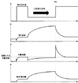
定数に適当な数値を設定し、PID制御のシミュレーションを行ったものを図5に示す。図5は横軸を工具の送り量(距離)とし、縦軸をそれぞれ切込み量、送り速度、主軸負荷値、積分項の値とした場合のグラフを示している。図5に示されるように、PID制御の下では、工具のワークに対する切り込み量の変化に合わせて工具の送り速度が変化し、主軸負荷の送りの距離が進むと共に、つまり時間が経過すると共に目標とする主軸負荷へ近づいていることが分かる。しかし、切り込み量が急激に増加している(A)において、主軸負荷が目標とする主軸負荷から大きく離れてしまっている。事前に切り込み量を推定する手法がなければ送り速度が高い状態で切り込み量の大きい領域へ入ってしまうため、この主軸負荷の乖離を防止するためには送り速度の最大値を設定する必要がある。そこで、図5と同様の条件で送り速度の上限値を設定し、単純に出力値をクランプしたものが図6となる。 FIG. 5 shows a simulation of PID control by setting an appropriate numerical value for the constant. FIG. 5 shows a graph in which the horizontal axis is the feed amount (distance) of the tool, and the vertical axis is the depth of cut, feed speed, spindle load value, and integral term value. As shown in FIG. 5, under PID control, the feed rate of the tool changes in accordance with the change in the amount of cutting of the tool with respect to the workpiece, and the feed distance of the spindle load increases, that is, the target passes with time. It can be seen that the spindle load is approaching. However, in (A) in which the cutting amount increases rapidly, the main shaft load is far away from the target main shaft load. If there is no method for estimating the cutting amount in advance, the feed rate will be high and the region where the cutting amount is large will be entered. Therefore, in order to prevent this spindle load deviation, it is necessary to set the maximum feed rate. . Therefore, FIG. 6 shows a case where the upper limit value of the feed speed is set under the same conditions as in FIG. 5 and the output value is simply clamped.
図6は図5と同じスケールでグラフを表示している。図6に示すように、送り速度の上限値が設定されたことで、送り速度が上限値よりも大きくならないように抑制されていることが分かる。また、(B)では図5の(A)に比べて主軸負荷が大きくなっていないことが分かる。しかし、(B)から(C)にかけて、送り速度が上限値となっており、主軸負荷が目標とする主軸負荷よりも高い状態で推移している。これは、速度の上限値を設定したことにより主軸負荷が減少し、目標とする主軸負荷と主軸負荷の偏差が大きくなり、それが原因で積分項の値が図5の場合と比べて大きくなり、(B)から(C)にかけて積分項が減少するのに時間がかかることにより、出力値である送り速度が減少するまでに時間を要してしまうためである。このように、単純に送り速度の上限値を設定し、出力をクランプすることは、送り速度が上限値へ張り付いてしまう現象を起こす原因となり、これにより工具やワークの破損、主軸モータや送り軸モータのオーバヒートを起こす要因となる。 FIG. 6 displays a graph on the same scale as FIG. As shown in FIG. 6, it can be seen that the upper limit value of the feed speed is set, so that the feed speed is suppressed from becoming larger than the upper limit value. In addition, in (B), it can be seen that the spindle load is not increased compared to (A) in FIG. However, from (B) to (C), the feed rate is the upper limit value, and the spindle load is in a state higher than the target spindle load. This is because the spindle load decreases due to the setting of the upper limit value of the speed, and the deviation between the target spindle load and the spindle load increases, which causes the integral term value to increase compared to the case of FIG. This is because, since it takes time for the integral term to decrease from (B) to (C), it takes time until the feed speed as the output value decreases. In this way, simply setting the upper limit value of the feed rate and clamping the output causes a phenomenon that the feed rate sticks to the upper limit value. This causes damage to the tool or workpiece, spindle motor or feed rate. It causes overheating of the shaft motor.
このように、数値制御装置のフィードバック制御において、出力値を制限または制御する場合、積分かそれに類する制御周期を跨いだ和や積などで表される「フィードバック値と目標値との偏差の解消を目的とした特徴量」(数1式においては右辺第2項の積分項により算出される値)が、意図せず増加または減少してしまうという問題がある。また、当該特徴量の意図しない変化によって、工作機械、加工工具または加工対象に不具合を発生させてしまう可能性があるという問題がある。 As described above, when the output value is limited or controlled in the feedback control of the numerical control device, it is expressed by a sum or product across the control cycle similar to the integral or the like, “to eliminate the deviation between the feedback value and the target value. There is a problem that the “target feature amount” (a value calculated by the integral term of the second term on the right side in Equation 1) increases or decreases unintentionally. Further, there is a problem that a malfunction may occur in a machine tool, a processing tool, or a processing target due to an unintended change in the feature amount.
そこで本発明の目的は、フィードバック制御をする際に遅延等を発生させることなく出力値を制御することが可能な数値制御装置を提供することである。 Therefore, an object of the present invention is to provide a numerical control device capable of controlling an output value without causing a delay or the like when performing feedback control.
本発明の数値制御装置では、フィードバック制御からの出力値を制限または制御する場合、フィードバック制御が望ましい出力値を出力するように、積分かそれに類する特徴量を逆算して更新することにより、上記問題を解決する。 In the numerical control device of the present invention, when the output value from the feedback control is limited or controlled, the above-mentioned problem is obtained by updating the integral or similar feature amount back so as to output the desired output value for the feedback control. To solve.
そして、本願の請求項1に係る発明は、プログラム指令に基づいて主軸と該主軸を駆動する軸とを備えた機械を制御する際に前記主軸の主軸負荷値が一定となるように前記軸の移動速度を制御するフィードバック制御を行う数値制御装置において、前記プログラム指令を解析して前記軸の移動を指令する指令データを生成する指令プログラム解析部と、前記主軸負荷値が一定となるように前記指令データによる前記軸の送り速度または送り速度に対するオーバライドをフィードバック制御により演算する速度演算処理を開始する速度演算部と、を備え、前記速度演算部は、演算した前記オーバライドと異なるオーバライドを出力する際にフィードバック制御で用いられる式のフィードバック値と目標値との偏差の解消を目的とした特徴量を、出力されるオーバライドから逆算された値で更新する、ことを特徴とする数値制御装置である。
In the invention according to
本発明によれば、積分かそれに類する特徴量の意図しない増加または減少がなくなり、制御の追従性が上がる。それにより、工作機械、加工工具または加工対象の不具合や、モータのオーバヒート等を抑制することができる。 According to the present invention, an unintended increase or decrease in integration or a similar feature quantity is eliminated, and the followability of control is improved. Thereby, the malfunction of a machine tool, a processing tool or a processing target, overheating of a motor, or the like can be suppressed.
以下、本発明の実施形態を図面と共に説明する。
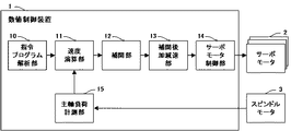
図1は、本発明の一実施形態による数値制御装置の機能ブロック図を示している。本実施形態による数値制御装置1は、指令プログラム解析部10、速度演算部11、補間部12、補間後加減速部13、サーボモータ制御部14、主軸負荷計測部15を備える。
指令プログラム解析部10は、図示しないメモリに記憶されるプログラム等から制御対象となる機械の動作を指令するブロックを逐次読み出して解析し、解析結果に基づいてサーボモータ2により駆動する軸の移動を指令する指令データを作成し、作成した該指令データを速度演算部11へと出力する。
Hereinafter, embodiments of the present invention will be described with reference to the drawings.
FIG. 1 shows a functional block diagram of a numerical controller according to an embodiment of the present invention. The
The command
速度演算部11は、主軸負荷計測部15により測定されるスピンドルモータ3の主軸負荷に基づいて、該主軸負荷が一定となるように指令プログラム解析部10から入力された指令データの送り速度に対するオーバライドを演算する。そして、演算されたオーバライドに基づいて速度が調整された指令データを補間部12へと出力する。
Based on the spindle load of the
補間部12は、速度演算部11から入力された速度調整後の指令データに基づいて、指令データによる指令経路上の補間周期毎の点として補間データを生成し、補間後加減速部13へと出力する。
補間後加減速部13は、補間部12から入力された補間データに基づいて補間周期毎の各軸の速度を算出し、結果データをサーボモータ制御部14へと出力する。
そして、サーボモータ制御部14は、補間後加減速部13の出力に基づいて制御対象となる機械の軸を駆動するサーボモータ2を制御する。
なお、図1ではスピンドルモータ制御回路及びスピンドルモータ用アンプ等は省略してある。
The
The post-interpolation acceleration /
The servo
In FIG. 1, the spindle motor control circuit, the spindle motor amplifier, and the like are omitted.
次に、速度演算部11により実行される速度の演算について説明する。本発明におけるPID制御とは下記の拡張を含むものとする。
●拡張)積分項は、任意の時刻に任意の値を代入できるものとし、そのような積分項を下端を省略した不定積分で表記する。
Next, the speed calculation executed by the
● Extended) An integral term can be assigned any value at any time, and such an integral term is expressed as an indefinite integral with the lower end omitted.
上記した拡張により、本発明では以下に示す数3式をPID制御の式として用いる。
Due to the above-described expansion, the following
本実施形態の数値制御装置1が備える速度演算部11は、前述した出力値の上限値を設定したPID制御において、数3式により算出された出力値O(t)が上限値Otを越えた時刻tに以下の数4式で算出される代替値Iを積分項へ代入する。以後、数3式により算出された出力値O(t)が上限値Otを越えている間は、数3式の積分項に各制御周期ごとに数4式に従って計算される代替値を代入してO(t)に代わりOtを出力する。数4式で算出される代替値Iは、出力されるオーバライドの値(上限値Ot)から逆算された値である。
In the PID control in which the upper limit value of the output value is set as described above, the
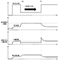
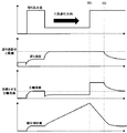
図6と同様の条件で上記処理を適用した場合のシミュレーション結果を図2に示す。図2に示すように、本実施形態の数値制御装置1では図6と同様に出力がクランプされるが、PID制御の計算を行うとクランプ後の出力が出力されるような値を積分項に代入する処理を加えている。そのため、(D)において送り速度が上限値へ達しても図6のように積分項の値は増大せず、一定値となっている。また、(E)において切り込み量が増大した瞬間の主軸負荷は図6と同等となるが、その直後に送り速度が低下し、主軸負荷も減少している。このように、本実施形態の数値制御装置1では積分項の意図しない増加または減少を防ぐことで制御の応答性が上がっていることが分かる。
FIG. 2 shows a simulation result when the above processing is applied under the same conditions as in FIG. As shown in FIG. 2, in the
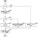
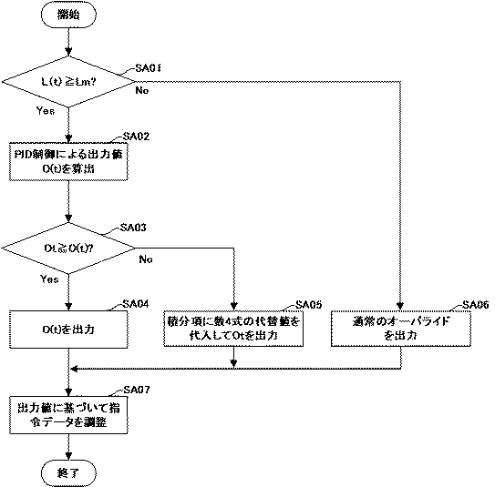
図3は、本実施形態による速度演算部11上で制御周期毎に実行される処理のフローチャートである。なお、図3のフローチャート中において、L(t)は現在の主軸負荷の値、Lmは本発明で導入される制御方法が有効となる主軸負荷の値、O(t)はPID制御が算出した出力値、Otは予め決められた出力値の上限値である。
●[ステップSA01]速度演算部11は、主軸負荷計測部15により測定されるスピンドルモータ3の現在の主軸負荷値L(t)が、あらかじめ設定された本実施形態の制御方法が有効となる主軸負荷値Lm以上であるか否かを判定する。主軸負荷値Lm以上である場合にはステップSA02へと処理を移行し、そうでない場合にはステップSA06へと処理を移行する。
FIG. 3 is a flowchart of processing executed for each control cycle on the
[Step SA01] The
●[ステップSA02]速度演算部11は、PID制御によるフィードバック制御により出力値O(t)を演算する。
●[ステップSA03]速度演算部11は、ステップSA02のPID制御により算出された出力値O(t)が予め決められた出力値の上限値であるOt以下であるか否かを判定する。Ot以下である場合にはステップSA04へと処理を移行し、Otを上回る場合にはステップSA05へと処理を移行する。
●[ステップSA04]速度演算部11は、ステップSA02で算出したO(t)を出力値とする。
●[ステップSA05]速度演算部11は、積分項に数4式の代替値を代入しOtを出力値とする。
●[ステップSA06]速度演算部11は、通常のオーバライドを出力する。
●[ステップSA07]速度演算部11は、算出された出力値に基づいて指令データを調整して補間部12へと出力し、今回の制御周期における処理を終了する。
[Step SA02] The
[Step SA03] The
[Step SA04] The
[Step SA05] The
[Step SA06] The
[Step SA07] The
以上、本発明の実施の形態について説明したが、本発明は上記した実施の形態の例にのみ限定されるものでなく、適宜の変更を加えることにより様々な態様で実施することができる。
例えば、上記した実施形態ではPID制御を用いたフィードバック制御に本発明を適用した場合を説明しており、PID制御の場合には積分項がフィードバック制御における制御周期を跨いだ和や積などで表される「フィードバック値と目標値との偏差の解消を目的とした特徴量」に該当しているので、積分項に対して代替値を代入するものとして説明しているが、他の制御方法に適用する場合には「フィードバック値と目標値との偏差の解消を目的とした特徴量」に該当する部分に対して出力値から逆算される代替値を代入するように構成すればよい。
While the embodiments of the present invention have been described above, the present invention is not limited to the above-described embodiments, and can be implemented in various modes by adding appropriate changes.
For example, the above embodiment describes the case where the present invention is applied to feedback control using PID control. In the case of PID control, the integral term is expressed as a sum or product across the control period in feedback control. The feature value is intended to eliminate the deviation between the feedback value and the target value. In the case of application, an alternative value that is calculated backward from the output value may be substituted for a portion corresponding to “a feature amount aimed at eliminating a deviation between the feedback value and the target value”.
1 数値制御装置
2 サーボモータ
3 スピンドルモータ
10 指令プログラム解析部
11 速度演算部
12 補間部
13 補間後加減速部
14 サーボモータ制御部
15 主軸負荷計測部
DESCRIPTION OF
Claims (1)
前記プログラム指令を解析して前記軸の移動を指令する指令データを生成する指令プログラム解析部と、
前記主軸負荷値が一定となるように前記指令データによる前記軸の送り速度または送り速度に対するオーバライドをフィードバック制御により演算する速度演算処理を開始する速度演算部と、
を備え、
前記速度演算部は、演算した前記オーバライドと異なるオーバライドを出力する際にフィードバック制御で用いられる式のフィードバック値と目標値との偏差の解消を目的とした特徴量を、出力されるオーバライドから逆算された値で更新する、
ことを特徴とする数値制御装置。 A numerical control device for performing feedback control for controlling the moving speed of the spindle so that the spindle load value of the spindle is constant when controlling a machine including the spindle and an axis that drives the spindle based on a program command In
A command program analysis unit for analyzing the program command and generating command data for commanding movement of the axis;
A speed calculation unit for starting a speed calculation process for calculating a feed speed of the shaft based on the command data or an override for the feed speed by feedback control so that the spindle load value is constant;
With
The speed calculation unit back-calculates the feature value for the purpose of eliminating the deviation between the feedback value and the target value used in feedback control when outputting an override different from the calculated override from the output override. Update with
A numerical controller characterized by that.
Priority Applications (4)
| Application Number | Priority Date | Filing Date | Title |
|---|---|---|---|
| JP2016081690A JP6514141B2 (en) | 2016-04-15 | 2016-04-15 | Numerical control device for controlling output value in feedback control |
| DE102017003649.7A DE102017003649B4 (en) | 2016-04-15 | 2017-04-13 | Numerical control unit |
| US15/487,878 US10261492B2 (en) | 2016-04-15 | 2017-04-14 | Numerical controller that controls an output value in feedback control |
| CN201710244859.0A CN107300893B (en) | 2016-04-15 | 2017-04-14 | Numerical controller |
Applications Claiming Priority (1)
| Application Number | Priority Date | Filing Date | Title |
|---|---|---|---|
| JP2016081690A JP6514141B2 (en) | 2016-04-15 | 2016-04-15 | Numerical control device for controlling output value in feedback control |
Publications (2)
| Publication Number | Publication Date |
|---|---|
| JP2017191536A true JP2017191536A (en) | 2017-10-19 |
| JP6514141B2 JP6514141B2 (en) | 2019-05-15 |
Family
ID=59981014
Family Applications (1)
| Application Number | Title | Priority Date | Filing Date |
|---|---|---|---|
| JP2016081690A Active JP6514141B2 (en) | 2016-04-15 | 2016-04-15 | Numerical control device for controlling output value in feedback control |
Country Status (4)
| Country | Link |
|---|---|
| US (1) | US10261492B2 (en) |
| JP (1) | JP6514141B2 (en) |
| CN (1) | CN107300893B (en) |
| DE (1) | DE102017003649B4 (en) |
Cited By (3)
| Publication number | Priority date | Publication date | Assignee | Title |
|---|---|---|---|---|
| DE102018002425A1 (en) | 2017-03-31 | 2018-10-31 | Fanuc Corporation | Numerical control device |
| DE112021001850T5 (en) | 2020-03-25 | 2023-01-26 | Fanuc Corporation | CONTROL DEVICE |
| JP2025019776A (en) * | 2023-07-28 | 2025-02-07 | ヤマザキマザック株式会社 | Workpiece machining method, program, and machine tool |
Families Citing this family (3)
| Publication number | Priority date | Publication date | Assignee | Title |
|---|---|---|---|---|
| JP6787950B2 (en) | 2018-06-04 | 2020-11-18 | ファナック株式会社 | Numerical control device |
| JP6940474B2 (en) * | 2018-12-05 | 2021-09-29 | ファナック株式会社 | Machine Tools |
| US11095661B2 (en) | 2019-05-29 | 2021-08-17 | Cisco Technology, Inc. | Enforcing data sovereignty policies in a cloud environment |
Citations (5)
| Publication number | Priority date | Publication date | Assignee | Title |
|---|---|---|---|---|
| JPH03161240A (en) * | 1989-11-20 | 1991-07-11 | Mitsubishi Motors Corp | Nc cutting device |
| JP2006518674A (en) * | 2003-02-25 | 2006-08-17 | ゼネラル・エレクトリック・カンパニイ | On-demand adaptive control system |
| JP2012032869A (en) * | 2010-07-28 | 2012-02-16 | Okouchi Kinzoku Co Ltd | Disc cutter feed control method, device and cutting apparatus using the same |
| US20160026170A1 (en) * | 2014-07-25 | 2016-01-28 | Fanuc Corporation | Numerical controller having suppressor that suppresses variation in velocity due to abrupt change in positional deviation |
| JP2017097701A (en) * | 2015-11-26 | 2017-06-01 | ファナック株式会社 | Numerical control device for controlling feed rate by spindle load |
Family Cites Families (7)
| Publication number | Priority date | Publication date | Assignee | Title |
|---|---|---|---|---|
| US3665493A (en) * | 1970-03-30 | 1972-05-23 | Bendix Corp | Adaptive numerical control system for a machine tool |
| US6859680B2 (en) * | 2002-03-01 | 2005-02-22 | Toshiba Kikai Kabushiki Kaisha | Numerical controlling unit having tool-breakage detecting function |
| US7508152B2 (en) | 2005-08-29 | 2009-03-24 | The Boeing Company | Apparatus for machine tool feedrate override using limiting parameters corresponding to actual spindle speed |
| JP2008225533A (en) * | 2007-03-08 | 2008-09-25 | Fanuc Ltd | Servo controller |
| US20100030366A1 (en) * | 2008-07-30 | 2010-02-04 | Jerry Gene Scherer | Method, system, and apparatus for on-demand integrated adaptive control of machining operations |
| JP4620148B2 (en) * | 2008-10-15 | 2011-01-26 | ファナック株式会社 | Servo motor control device |
| JP5863919B1 (en) * | 2014-09-30 | 2016-02-17 | ファナック株式会社 | Machine tool controller |
-
2016
- 2016-04-15 JP JP2016081690A patent/JP6514141B2/en active Active
-
2017
- 2017-04-13 DE DE102017003649.7A patent/DE102017003649B4/en active Active
- 2017-04-14 US US15/487,878 patent/US10261492B2/en active Active
- 2017-04-14 CN CN201710244859.0A patent/CN107300893B/en active Active
Patent Citations (5)
| Publication number | Priority date | Publication date | Assignee | Title |
|---|---|---|---|---|
| JPH03161240A (en) * | 1989-11-20 | 1991-07-11 | Mitsubishi Motors Corp | Nc cutting device |
| JP2006518674A (en) * | 2003-02-25 | 2006-08-17 | ゼネラル・エレクトリック・カンパニイ | On-demand adaptive control system |
| JP2012032869A (en) * | 2010-07-28 | 2012-02-16 | Okouchi Kinzoku Co Ltd | Disc cutter feed control method, device and cutting apparatus using the same |
| US20160026170A1 (en) * | 2014-07-25 | 2016-01-28 | Fanuc Corporation | Numerical controller having suppressor that suppresses variation in velocity due to abrupt change in positional deviation |
| JP2017097701A (en) * | 2015-11-26 | 2017-06-01 | ファナック株式会社 | Numerical control device for controlling feed rate by spindle load |
Cited By (9)
| Publication number | Priority date | Publication date | Assignee | Title |
|---|---|---|---|---|
| DE102018002425A1 (en) | 2017-03-31 | 2018-10-31 | Fanuc Corporation | Numerical control device |
| JP2018173735A (en) * | 2017-03-31 | 2018-11-08 | ファナック株式会社 | Numerical control device |
| US10649434B2 (en) | 2017-03-31 | 2020-05-12 | Fanuc Corporation | Numerical controller |
| DE102018002425B4 (en) | 2017-03-31 | 2023-05-11 | Fanuc Corporation | Numerical control device |
| DE112021001850T5 (en) | 2020-03-25 | 2023-01-26 | Fanuc Corporation | CONTROL DEVICE |
| DE112021001850B4 (en) * | 2020-03-25 | 2025-03-06 | Fanuc Corporation | CONTROL DEVICE |
| US12259703B2 (en) | 2020-03-25 | 2025-03-25 | Fanuc Corporation | Control device |
| JP2025019776A (en) * | 2023-07-28 | 2025-02-07 | ヤマザキマザック株式会社 | Workpiece machining method, program, and machine tool |
| JP7686358B2 (en) | 2023-07-28 | 2025-06-02 | ヤマザキマザック株式会社 | Workpiece machining method, program, and machine tool |
Also Published As
| Publication number | Publication date |
|---|---|
| CN107300893A (en) | 2017-10-27 |
| JP6514141B2 (en) | 2019-05-15 |
| DE102017003649B4 (en) | 2022-03-24 |
| US10261492B2 (en) | 2019-04-16 |
| US20170300030A1 (en) | 2017-10-19 |
| DE102017003649A1 (en) | 2017-10-19 |
| CN107300893B (en) | 2020-03-31 |
Similar Documents
| Publication | Publication Date | Title |
|---|---|---|
| JP2017191536A (en) | Numerical controller for controlling output values during feedback control | |
| JP6333797B2 (en) | A numerical control device that controls the feed rate by the spindle load | |
| US9851709B2 (en) | Numerical control device | |
| JP6321583B2 (en) | Numerical control device for 3D interference check corresponding to speed change | |
| JP6321611B2 (en) | Servo controller that decelerates and stops in dead zone of analog input voltage input command | |
| JP6174652B2 (en) | Numerical control device with automatic parameter selection function according to the size of the processing area | |
| JP5715189B2 (en) | Numerical control device with a function to smoothly change the feed rate when the override changes | |
| JP2016151951A (en) | Numerical control device for reducing load of machine | |
| JP6017509B2 (en) | Numerical control device that smoothly changes feed rate when operation is stopped | |
| JP6100816B2 (en) | Numerical control device for speed control to suppress excessive position deviation | |
| JP6321605B2 (en) | Numerical control device for speed control by curvature and curvature variation | |
| CN103801775B (en) | The control device of wire cutting machine, wire cutting machine and wire cutting method | |
| JP6081954B2 (en) | Numerical control device that speeds up the reversing operation of machine tools | |
| US11126163B2 (en) | Numerical controller | |
| JP2017033345A (en) | Synchronous control device having function of eliminating shock of synchronous start block | |
| JP2018030162A (en) | Laser control device | |
| JP2016115074A (en) | Numerical control device with interference avoidance/positioning function | |
| JP2017117252A (en) | Numerical control apparatus performing easily adjustment of press machine | |
| CN106707971B (en) | Numerical control device | |
| JP2016134078A (en) | Numerical control device for control over machine tool based on skiving processing command | |
| JP2019025491A (en) | Numerical control device |
Legal Events
| Date | Code | Title | Description |
|---|---|---|---|
| A977 | Report on retrieval |
Free format text: JAPANESE INTERMEDIATE CODE: A971007 Effective date: 20180719 |
|
| A131 | Notification of reasons for refusal |
Free format text: JAPANESE INTERMEDIATE CODE: A131 Effective date: 20180807 |
|
| A521 | Request for written amendment filed |
Free format text: JAPANESE INTERMEDIATE CODE: A523 Effective date: 20181009 |
|
| TRDD | Decision of grant or rejection written | ||
| A01 | Written decision to grant a patent or to grant a registration (utility model) |
Free format text: JAPANESE INTERMEDIATE CODE: A01 Effective date: 20190312 |
|
| A61 | First payment of annual fees (during grant procedure) |
Free format text: JAPANESE INTERMEDIATE CODE: A61 Effective date: 20190411 |
|
| R150 | Certificate of patent or registration of utility model |
Ref document number: 6514141 Country of ref document: JP Free format text: JAPANESE INTERMEDIATE CODE: R150 |