JP2017191230A - Image forming apparatus and image forming method - Google Patents
Image forming apparatus and image forming method Download PDFInfo
- Publication number
- JP2017191230A JP2017191230A JP2016081029A JP2016081029A JP2017191230A JP 2017191230 A JP2017191230 A JP 2017191230A JP 2016081029 A JP2016081029 A JP 2016081029A JP 2016081029 A JP2016081029 A JP 2016081029A JP 2017191230 A JP2017191230 A JP 2017191230A
- Authority
- JP
- Japan
- Prior art keywords
- toner
- particles
- resin
- carrier
- resin particles
- Prior art date
- Legal status (The legal status is an assumption and is not a legal conclusion. Google has not performed a legal analysis and makes no representation as to the accuracy of the status listed.)
- Granted
Links
Images


Abstract
Description
本発明は、画像形成装置及び画像形成方法に関する。 The present invention relates to an image forming apparatus and an image forming method.
特許文献1には、感光体と、帯電装置(帯電ローラー)と、露光装置と、現像装置とを備える画像形成装置が開示されている。特許文献1に記載の画像形成装置では、特定の固形潤滑剤及びファーブラシを用いて感光体の表面に潤滑剤を供給している。 Patent Document 1 discloses an image forming apparatus including a photoreceptor, a charging device (charging roller), an exposure device, and a developing device. In the image forming apparatus described in Patent Document 1, a lubricant is supplied to the surface of the photoreceptor using a specific solid lubricant and a fur brush.
しかしながら、画像形成装置による連続印刷において、感光体の摩耗、感光体の汚染、及び帯電装置の汚染を好適に抑制するためには、特許文献1に開示される技術だけでは不十分であると考えられる。例えば、特許文献1に記載の画像形成装置では、特定の固形潤滑剤及びファーブラシを必要とすることで、低コスト化が困難になる。 However, in the continuous printing by the image forming apparatus, it is considered that the technique disclosed in Patent Document 1 is not sufficient for suitably suppressing the abrasion of the photoreceptor, the contamination of the photoreceptor, and the contamination of the charging device. It is done. For example, the image forming apparatus described in Patent Document 1 requires a specific solid lubricant and fur brush, which makes it difficult to reduce the cost.
本発明は、上記実情に鑑みてなされたものであり、連続印刷において、感光体の摩耗、感光体の汚染、及び帯電装置の汚染を抑制しつつ、継続的に高画質の画像を形成し続けることができる画像形成装置及び画像形成方法を提供することを目的とする。 The present invention has been made in view of the above circumstances, and continuously forms high-quality images while suppressing photoconductor wear, photoconductor contamination, and charging device contamination in continuous printing. An object of the present invention is to provide an image forming apparatus and an image forming method.
本発明に係る画像形成装置は、像担持体と、接触帯電方式の帯電装置と、露光装置と、現像装置とを備える。前記帯電装置は、前記像担持体の表面に接触しながら前記像担持体の前記表面を帯電させるように構成される。前記露光装置は、前記帯電した像担持体の表面に露光を行うことにより、前記像担持体の表面に静電潜像を形成するように構成される。前記現像装置は、前記静電潜像を現像するための現像剤を収容する収容部を有する。初期状態において、前記収容部には、少なくともトナーを含む現像剤が実質的に収容されている。前記トナーは、トナー母粒子と、前記トナー母粒子の表面に付着した外添剤とを備えるトナー粒子を、複数含む。前記トナー粒子は、前記外添剤として無機粒子及び樹脂粒子を備える。前記樹脂粒子の個数平均1次粒子径は70nm以上200nm以下である。前記樹脂粒子の、温度160℃かつ圧力0.1kgf/mm2での5分間加圧後のブロッキング率は、目開き75μmのメッシュによる測定で20質量%以上45質量%以下である。超音波処理を5分間行った状態のトナーの分散液について測定される、前記トナーの分散液中の前記無機粒子の遊離率は、蛍光X線スペクトルのピーク強度比率で5%以下であり、前記トナーの分散液中の前記樹脂粒子の遊離率は、GC/MS法マススペクトルのピーク面積比率で10%以上30%以下である。 An image forming apparatus according to the present invention includes an image carrier, a contact charging type charging device, an exposure device, and a developing device. The charging device is configured to charge the surface of the image carrier while being in contact with the surface of the image carrier. The exposure apparatus is configured to form an electrostatic latent image on the surface of the image carrier by exposing the surface of the charged image carrier. The developing device includes a storage unit that stores a developer for developing the electrostatic latent image. In an initial state, the storage portion substantially stores a developer containing at least toner. The toner includes a plurality of toner particles including toner mother particles and an external additive attached to the surface of the toner mother particles. The toner particles include inorganic particles and resin particles as the external additive. The number average primary particle diameter of the resin particles is 70 nm or more and 200 nm or less. The blocking rate of the resin particles after pressing for 5 minutes at a temperature of 160 ° C. and a pressure of 0.1 kgf / mm 2 is 20% by mass or more and 45% by mass or less as measured with a mesh having an opening of 75 μm. The liberation rate of the inorganic particles in the toner dispersion measured in the toner dispersion after sonication for 5 minutes is 5% or less in terms of the peak intensity ratio of the fluorescent X-ray spectrum. The liberation rate of the resin particles in the toner dispersion is 10% or more and 30% or less as a peak area ratio of the GC / MS mass spectrum.
本発明に係る画像形成方法は、帯電工程と、露光工程と、現像工程とを含む。前記帯電工程では、像担持体の表面に接触しながら前記像担持体の前記表面を帯電させる。前記露光工程では、前記帯電した像担持体の表面に露光を行うことにより、前記像担持体の表面に静電潜像を形成する。前記現像工程では、現像装置の収容部内のトナーを前記像担持体に供給して、前記トナーで前記静電潜像を現像する。前記トナーは、トナー母粒子と、前記トナー母粒子の表面に付着した外添剤とを備えるトナー粒子を、複数含む。前記トナー粒子は、前記外添剤として無機粒子及び樹脂粒子を備える。前記樹脂粒子の個数平均1次粒子径は70nm以上200nm以下である。前記樹脂粒子の、温度160℃かつ圧力0.1kgf/mm2での5分間加圧後のブロッキング率は、目開き75μmのメッシュによる測定で20%以上45%以下である。超音波処理を5分間行った状態のトナーの分散液について測定される、前記トナーの分散液中の前記無機粒子の遊離率は、蛍光X線分析によるピーク強度比率で5%以下であり、前記トナーの分散液中の前記樹脂粒子の遊離率は、GC/MS法によるピーク面積比率で10%以上30%以下である。 The image forming method according to the present invention includes a charging step, an exposure step, and a development step. In the charging step, the surface of the image carrier is charged while contacting the surface of the image carrier. In the exposure step, an electrostatic latent image is formed on the surface of the image carrier by exposing the surface of the charged image carrier. In the developing step, toner in a housing portion of a developing device is supplied to the image carrier, and the electrostatic latent image is developed with the toner. The toner includes a plurality of toner particles including toner mother particles and an external additive attached to the surface of the toner mother particles. The toner particles include inorganic particles and resin particles as the external additive. The number average primary particle diameter of the resin particles is 70 nm or more and 200 nm or less. The blocking rate of the resin particles after pressing for 5 minutes at a temperature of 160 ° C. and a pressure of 0.1 kgf / mm 2 is 20% or more and 45% or less as measured with a mesh having an opening of 75 μm. The liberation rate of the inorganic particles in the toner dispersion, which is measured for a toner dispersion in a state where ultrasonic treatment is performed for 5 minutes, is 5% or less as a peak intensity ratio by fluorescent X-ray analysis. The liberation rate of the resin particles in the toner dispersion is 10% or more and 30% or less as a peak area ratio according to the GC / MS method.
本発明によれば、連続印刷において、感光体の摩耗、感光体の汚染、及び帯電装置の汚染を抑制しつつ、継続的に高画質の画像を形成し続けることができる画像形成装置及び画像形成方法を提供することが可能になる。 According to the present invention, in continuous printing, an image forming apparatus and an image forming apparatus capable of continuously forming a high-quality image while suppressing photoconductor abrasion, photoconductor contamination, and charging device contamination. It becomes possible to provide a method.
本発明の実施形態について説明する。なお、粉体(より具体的には、トナー母粒子、外添剤、トナー、又はキャリア等)に関する評価結果(形状又は物性などを示す値)は、何ら規定していなければ、粉体から平均的な粒子を相当数選び取って、それら平均的な粒子の各々について測定した値の個数平均である。 An embodiment of the present invention will be described. Note that the evaluation results (values indicating shape, physical properties, etc.) regarding the powder (more specifically, toner base particles, external additives, toner, carrier, etc.) are average values from the powder unless otherwise specified. This is the number average of the values measured for each of the average particles by selecting a significant number of such particles.
粉体の個数平均粒子径は、何ら規定していなければ、顕微鏡を用いて測定された1次粒子の円相当径(粒子の投影面積と同じ面積を有する円の直径)の個数平均値である。また、粉体の体積中位径(D50)の測定値は、何ら規定していなければ、レーザー回折/散乱式粒度分布測定装置(株式会社堀場製作所製「LA−750」)を用いて測定した値である。また、軟化点(Tm)は、何ら規定していなければ、高化式フローテスター(株式会社島津製作所製「CFT−500D」)を用いて測定した値である。高化式フローテスターで測定されたS字カーブ(横軸:温度、縦軸:ストローク)において、「(ベースラインストローク値+最大ストローク値)/2」となる温度が、Tm(軟化点)に相当する。また、酸価の測定値は、何ら規定していなければ、「JIS(日本工業規格)K0070−1992」に従って測定した値である。 The number average particle diameter of the powder is the number average value of the equivalent circle diameter of primary particles (diameter of a circle having the same area as the projected area of the particles) measured using a microscope unless otherwise specified. . Moreover, the measured value of the volume median diameter (D 50 ) of the powder is measured using a laser diffraction / scattering particle size distribution measuring device (“LA-750” manufactured by Horiba, Ltd.) unless otherwise specified. It is the value. Moreover, the softening point (Tm) is a value measured using a Koka type flow tester (“CFT-500D” manufactured by Shimadzu Corporation) unless otherwise specified. In the S curve (horizontal axis: temperature, vertical axis: stroke) measured with the Koka type flow tester, the temperature that becomes "(baseline stroke value + maximum stroke value) / 2" is Tm (softening point). Equivalent to. Further, the measured value of the acid value is a value measured according to “JIS (Japanese Industrial Standard) K0070-1992” unless otherwise specified.
以下、化合物名の後に「系」を付けて、化合物及びその誘導体を包括的に総称する場合がある。化合物名の後に「系」を付けて重合体名を表す場合には、重合体の繰返し単位が化合物又はその誘導体に由来することを意味する。また、アクリル及びメタクリルを包括的に「(メタ)アクリル」と総称する場合がある。また、アクリロニトリル及びメタクリロニトリルを包括的に「(メタ)アクリロニトリル」と総称する場合がある。また、シリカ粒子は、何ら規定していなければ、乾式シリカ粒子を意味する。 Hereinafter, a compound and its derivatives may be generically named by adding “system” after the compound name. When the name of a polymer is expressed by adding “system” after the compound name, it means that the repeating unit of the polymer is derived from the compound or a derivative thereof. Acrylic and methacrylic are sometimes collectively referred to as “(meth) acrylic”. Further, acrylonitrile and methacrylonitrile may be collectively referred to as “(meth) acrylonitrile”. Further, the silica particles mean dry silica particles unless otherwise specified.
以下、図1及び図2を参照して、本実施形態に係る画像形成装置の一例(画像形成装置100)について説明する。 Hereinafter, an example of the image forming apparatus (image forming apparatus 100) according to the present embodiment will be described with reference to FIGS.
画像形成装置100は、タンデム方式の電子写真装置である。図1に示すように、画像形成装置100は、現像装置11a〜11dと、感光体ドラム12a〜12dと、転写装置10と、定着装置17と、クリーニング装置18とを備える。転写装置10は、転写ベルト13と、駆動ローラー14aと、従動ローラー14bと、テンションローラー14cと、1次転写ローラー15a〜15dと、2次転写ローラー16とを備える。転写ベルト13は、駆動ローラー14a、従動ローラー14b、及びテンションローラー14cに張架されている。転写ベルト13は、駆動ローラー14aにより駆動されて、図1中の矢印で示される方向に回転する。定着装置17は、例えば、加熱ローラー及び加圧ローラーを備えるニップ定着方式の定着装置である。クリーニング装置18は、転写ベルト13上に残留するトナーを除去する。画像形成装置100を用いて画像を形成する場合には、例えば2成分現像剤を、現像装置11a〜11dの各々にセットする。画像形成装置100は、各種センサーの出力に基づいて、画像形成装置100の動作を電子制御する制御部20を備える。制御部20は、例えば、CPU(Central Processing Unit)と、RAM(Random Access Memory)と、プログラムを記憶し、かつ、所定のデータを書換え可能に記憶する記憶装置とを備える。ユーザーは、図示しない入力部(例えば、キーボード、マウス、又はタッチパネル)を通じて、制御部20に指示(電気信号)を与えることができる。
The
2成分現像剤は、トナーとキャリアとを含む。トナー及びキャリアはそれぞれ、多数の粒子から構成される粉体である。トナーは、後述の構成を有するトナー粒子を、複数含む。キャリアは、後述の構成を有するキャリア粒子を、複数含む。2成分現像剤に含まれるトナーは、例えば正帯電性トナーとして用いることができる。正帯電性トナーは、キャリアとの摩擦により正に帯電する。キャリアに含まれるキャリア粒子は、磁性を有する。キャリア粒子に磁性を付与するためには、磁性材料(例えば、フェライトのような強磁性物質)でキャリア粒子の少なくとも一部を形成してもよいし、磁性粒子を分散させた樹脂でキャリア粒子の少なくとも一部を形成してもよい。 The two-component developer includes a toner and a carrier. The toner and the carrier are each a powder composed of a large number of particles. The toner includes a plurality of toner particles having the configuration described below. The carrier includes a plurality of carrier particles having the configuration described below. The toner contained in the two-component developer can be used as, for example, a positively chargeable toner. The positively chargeable toner is positively charged by friction with the carrier. Carrier particles contained in the carrier have magnetism. In order to impart magnetism to the carrier particles, at least a part of the carrier particles may be formed of a magnetic material (for example, a ferromagnetic material such as ferrite), or the carrier particles may be formed of a resin in which the magnetic particles are dispersed. You may form at least one part.
画像形成装置100は、画像データに基づいて感光体ドラム12a〜12dの各々の表層部(感光層)に静電潜像を形成する。次に、形成された静電潜像を、現像装置11a〜11dの各々にセットされた2成分現像剤(トナー及びキャリア)を用いて現像する。現像装置11a〜11dはそれぞれ、図2に示される構成を有する。以下、区別する必要がない場合(共通の性質などについて述べる場合)には、現像装置11a〜11dの各々を現像装置11と記載し、感光体ドラム12a〜12dの各々を感光体ドラム12と記載する。図2は、現像装置11の内部構成を示す断面図である。
The
図2に示すように、画像形成装置100は、感光体ドラム12の感光層に一様に静電気を帯びさせるための帯電装置を備える。帯電装置は、感光体ドラム12の表面Fに当接する帯電性部材21(例えば、帯電ローラー)を備え、接触帯電方式で感光層を帯電させるように構成される。帯電した帯電性部材21(例えば、直流電圧の印加により、又は直流電圧に交流電圧を重畳したAC重畳直流電圧の印加により、帯電させた部材)が感光層に接触することで、感光層が帯電する。帯電性部材21は、ローラーに限られず任意であり、ブラシ又はブレードであってもよい。帯電性部材21は、例えばバネの付勢力により感光体ドラム12の表面Fに押し付けられていてもよい。また、画像形成装置100は、図1に示すように、感光体ドラム12a〜12dの各々の感光層に静電潜像を形成するための露光装置22を備える。露光装置22は、光源として、例えばLED(発光ダイオード)ヘッドを備える。露光装置22は、画像データに基づいて、例えばLEDヘッドから発せられた光を、感光体ドラム12a〜12dの各々の感光層に選択的に照射するように構成される。帯電した感光層に露光装置22が露光を行うことにより、静電潜像が感光層に形成される。また、画像形成装置100は、図2に示すように、感光体ドラム12の表面Fに付着した物質(付着物)を除去するためのクリーニングブレード23(例えば、ゴム製の板)を備える。クリーニングブレード23は、例えばバネの付勢力により感光体ドラム12の表面Fに押し付けられており、感光体ドラム12上の付着物を掻き落とすように構成される。感光体ドラム12の回転により、クリーニングブレード23は、感光体ドラム12の表面Fに対して相対摺動する。
As shown in FIG. 2, the
図2に示すように、現像装置11は、現像ローラー111と、磁気ローラー112と、規制ブレード112dと、第1攪拌シャフト113と、第2攪拌シャフト114とを備える。また、現像装置11は、搬送部R1と、収容部R2及びR3とを有する。搬送部R1は、現像ローラー111及び磁気ローラー112を収容する。また、収容部R2は第1攪拌シャフト113を収容し、収容部R3は第2攪拌シャフト114を収容する。現像ローラー111は、感光体ドラム12の近傍に配置される。図2に示す例では、現像ローラー111と感光体ドラム12との間に、隙間が設けられている。
As shown in FIG. 2, the developing
現像装置11は、トナーで静電潜像を現像するように構成される。初期状態(未使用状態)の画像形成装置100において、収容部R2及びR3はそれぞれ、トナー(初期トナー)及びキャリアを含む2成分現像剤を収容している。ただし、トナー(初期トナー)及びキャリアは、画像形成装置100を使用開始する時の初期設定(インストール操作)により現像装置11の収容部R2及びR3に自動的に投入されてもよい。
The developing
現像装置11には、補給用トナーコンテナ115が設けられている。補給用トナーコンテナ115(トナー補給部)は、補給用トナーを現像装置11内へ補給するように構成される。補給用トナーコンテナ115は補給用トナーを収容している。補給用トナーコンテナ115内の補給用トナーは、現像装置11(詳しくは、収容部R3)に供給される。補給用トナーコンテナ115は、補給量調整部材115aを備える。トナーの補給量(補給用トナーコンテナ115から現像装置11へ供給されるトナーの量)は、補給量調整部材115aによって制御できる。補給量調整部材115aは、例えば、制御部20により回転動作を制御されるスクリューシャフトから構成される。
The developing
初期トナーと補給用トナーとは、互いに同じトナーであってもよいし、異なるトナーであってもよい。ただし、安定して好適な画像の形成を行うためには、初期トナーと補給用トナーとが互いに同じトナーであることが好ましい。なお、2以上のトナーが同じであることは、それらトナーが互換性を有するほどに、それらトナーの間に実質的に性質上の差異がないことを意味する。 The initial toner and the replenishing toner may be the same toner or different toners. However, in order to stably form a suitable image, the initial toner and the replenishing toner are preferably the same toner. Note that the fact that two or more toners are the same means that there is substantially no difference in properties between the toners so that the toners are compatible.
第1攪拌シャフト113及び第2攪拌シャフト114はそれぞれ、螺旋状の攪拌羽根を有する。第1攪拌シャフト113及び第2攪拌シャフト114は、現像装置11内(詳しくは、収容部R2及びR3)の現像剤を攪拌しながら、互いに逆方向に現像剤を搬送する。現像剤が攪拌されることで、現像剤中のトナーは摩擦帯電し、現像剤中のキャリアはトナーを担持する。
Each of the
磁気ローラー112は、マグネットロールと、スリーブとを備える。スリーブは、非磁性の筒体(例えば、アルミニウムパイプ)である。非回転のマグネットロールの周りをスリーブが回転できるように、マグネットロールのシャフトとスリーブとがフランジを介して接続されている。磁気ローラー112は、例えばモーター(図示せず)によって駆動されて、図2中の矢印の方向に回転する。
The
磁気ローラー112のマグネットロールは、所定の磁極(例えば、永久磁石に基づく磁極)を有する。以下、磁気ローラー112のマグネットロールが有する磁極のうち、第1攪拌シャフト113に対向する磁極を汲上極112aと、現像ローラー111に対向する磁極を主極112bと、規制ブレード112dに対向する磁極を規制極112cと、それぞれ記載する。
The magnet roll of the
磁気ローラー112は、図2中の矢印の方向にスリーブを回転させながら、収容部R2にあるキャリアを汲上極112aの磁力により引き付けて、スリーブの表面に現像剤(キャリア及びトナー)を担持する。現像剤は、キャリアの表面にトナーが担持された状態で、磁気ローラー112の表面に担持される。その結果、キャリアによる磁気ブラシが磁気ローラー112の表面に形成される。磁気ブラシは、磁気ローラー112の表面に穂立ちしたキャリア粒子クラスターである。穂状に連なったキャリア粒子の表面にはトナーが付着している。磁気ブラシの厚さ(穂の高さ)は、規制ブレード112dによって所定の厚さに規制される。規制ブレード112dは、例えば規制極112cの磁力によって磁化され得る板状の磁性部材である。現像ローラー111と磁気ローラー112とは、磁気ローラー112上の磁気ブラシが現像ローラー111に接触する程度の間隔で配置されている。また、主極112bの磁力は、磁気ローラー112の表面に担持された現像剤(トナー及びキャリア)のうちトナーのみを現像ローラー111に供給するように作用する。
While rotating the sleeve in the direction of the arrow in FIG. 2, the
現像ローラー111は、マグネットロールと、現像スリーブとを備える。現像スリーブは、非磁性の筒体(例えば、アルミニウムパイプ)である。マグネットロールは現像スリーブ内(筒内)に位置し、現像スリーブは現像ローラー111の表層部に位置する。非回転のマグネットロールの周りを現像スリーブが回転できるように、マグネットロールのシャフトと現像スリーブとがフランジを介して接続されている。現像ローラー111は、例えばモーター(図示せず)によって駆動されて、図2中の矢印の方向に回転する。
The developing
感光体ドラム12としては、例えば有機感光体(OPC:Organic PhotoConductor)ドラムを使用することが好ましい。感光体ドラム12は、円柱状の外形を有する。感光体ドラム12は、芯材として金属製の筒体(例えば、アルミニウムパイプ)を備え、その芯材の外側に、電荷発生剤及び電荷輸送剤を含有する単層型感光層、又は積層型感光層(例えば、下引き層、電荷発生層、及び電荷輸送層)をさらに備える。また、感光層の表面に、感光層を保護するための保護層が設けられてもよい。感光体ドラム12は、回転可能な態様で例えば画像形成装置100の筐体に支持されており、例えばモーター(図示せず)によって駆動されて、図2中の矢印の方向に回転する。
As the
磁気ローラー112に担持された現像剤中のトナーを感光体ドラム12に供給するためには、例えば現像ローラー111及び磁気ローラー112の少なくとも一方にバイアス(電圧)を印加することで、両者の表面電位の間に電位差を生じさせる。この電位差によって、磁気ローラー112に担持された現像剤中のトナーが現像ローラー111に移動し、現像ローラー111の表面に担持される。詳しくは、現像ローラー111のスリーブと磁気ローラー112のスリーブとがそれぞれ図2中の矢印の方向に回転することで、磁気ローラー112の表面に担持された現像剤(特に、キャリアの表面に担持されたトナー)と現像ローラー111とが擦れ合う。磁気ローラー112の表面に担持された現像剤中のトナーは、現像ローラー111に電気的に引き付けられる。その結果、現像ローラー111の表面にトナー層が形成される。
In order to supply the toner in the developer carried on the
さらに、現像ローラー111及び感光体ドラム12の少なくとも一方にバイアス(電圧)が印加されることで、両者の表面電位の間に電位差が生じる。この電位差によって、現像ローラー111に担持されたトナーが感光体ドラム12に移動し易くなる。現像ローラー111に担持されたトナーは、感光体ドラム12に形成された静電潜像の露光部位(例えば、露光によって周囲よりも電位の低下した部位)に電気的に引き付けられて、感光体ドラム12に向かって飛翔する。その結果、感光体ドラム12の表面Fにトナー像が形成される。
Furthermore, by applying a bias (voltage) to at least one of the developing
図1を参照して説明を続ける。上記のように、画像形成装置100では、現像装置11a、11b、11c、11dがそれぞれ、感光体ドラム12a、12b、12c、12d(それぞれ像担持体)に形成された静電潜像を現像する。画像形成装置100は、各感光体ドラム12にトナー像を形成した後、1次転写ローラー15a〜15dの各々にバイアス(電圧)をかけて、感光体ドラム12a〜12dの各々に付着したトナー(トナー像)を転写ベルト13(中間転写体)に転写(1次転写)する。さらに、2次転写ローラー16にバイアス(電圧)をかけることにより、転写ベルト13上のトナー像を、搬送される記録媒体P(被転写体)に転写(2次転写)する。その後、定着装置17が、トナーを加熱して、記録媒体Pにトナーを定着させる。これにより、記録媒体Pに画像が形成される。なお、転写工程の後、感光体ドラム12上に残ったトナーは、感光体ドラム12上の他の付着物と共に、クリーニングにより除去される。クリーニング工程では、クリーニングブレード23のエッジ部で感光体ドラム12の表面Fを擦ることにより、感光体ドラム12上の付着物を掻き取って除去する。
The description will be continued with reference to FIG. As described above, in the
画像形成装置100は、複数の感光体ドラム12a〜12dを備える。このため、画像形成装置100は、1次転写工程において、複数の感光体ドラム12a〜12dの各々に形成されたトナー像を順次、転写ベルト13に転写することにより、転写ベルト13上に、複数種のトナー像(例えば、異なる色のトナー像)を重ねることができる。また、画像形成装置100では、2次転写工程において、転写ベルト13上に重ねたトナー像を記録媒体Pに一括転写することができる。例えば、ブラック、イエロー、マゼンタ、及びシアンの4色のトナー像を重ね合わせることで、フルカラー画像を形成することができる。記録媒体Pとしては、例えば印刷用紙を用いることができる。
The
画像形成装置100は、下記タッチダウン現像法で静電潜像を現像するように構成されるタッチダウン画像形成装置である。
The
(タッチダウン現像法)
画像形成方法が、磁気ブラシの形成と、トナー層の形成と、静電潜像の形成と、トナー像の形成とを含む。磁気ブラシの形成では、トナー及びキャリアを含む2成分現像剤を、キャリアの表面にトナーが担持された状態で磁性担持体(例えば、図2に示される磁気ローラー112)の表面に担持させる。2成分現像剤が磁性担持体に担持されることで、キャリアによる磁気ブラシが磁性担持体の表面に形成される。トナー層の形成では、磁性担持体の表面に担持された2成分現像剤のうちトナーを、磁性担持体に対向するトナー担持体(例えば、図2に示される現像ローラー111)に移動させて、トナー担持体の表面にトナー層を形成する。静電潜像の形成では、トナー担持体に対向する像担持体(例えば、図2に示される感光体ドラム12)の表面に静電潜像を形成する。トナー像の形成では、トナー担持体の表面に形成されたトナー層中のトナーを、像担持体に向けて飛翔させて、像担持体の表面にトナー像を形成する。
(Touch-down development method)
The image forming method includes forming a magnetic brush, forming a toner layer, forming an electrostatic latent image, and forming a toner image. In the formation of the magnetic brush, a two-component developer containing toner and carrier is carried on the surface of a magnetic carrier (for example, the
本実施形態に係る画像形成装置は、次に示す構成(以下、基本構成と記載する)を有する。 The image forming apparatus according to the present embodiment has the following configuration (hereinafter referred to as a basic configuration).
(画像形成装置の基本構成)
像担持体(例えば、図2に示される感光体ドラム12)と、接触帯電方式の帯電装置(例えば、図2に示される帯電性部材21を備える帯電装置)と、露光装置(例えば、図1に示される露光装置22)と、現像装置(例えば、図2に示される現像装置11)とを備える。帯電装置は、像担持体の表面に接触しながら像担持体の表面を帯電させるように構成される。露光装置は、帯電した像担持体の表面に露光を行うことにより、像担持体の表面に静電潜像を形成するように構成される。現像装置は、静電潜像を現像するための現像剤を収容する収容部を有する。初期状態において、現像装置の収容部には、少なくともトナー(初期トナー)を含む現像剤が実質的に収容されている。トナーは、トナー母粒子と、トナー母粒子の表面に付着した外添剤とを備えるトナー粒子を、複数含む。トナー粒子は、外添剤として無機粒子及び樹脂粒子を備える。樹脂粒子の個数平均1次粒子径は70nm以上200nm以下である。樹脂粒子の、温度160℃かつ圧力0.1kgf/mm2での5分間加圧後のブロッキング率は、目開き75μmのメッシュによる測定で20質量%以上45質量%以下である。超音波処理を5分間行った状態の上記トナーの分散液(以下、トナー分散液と記載する場合がある)について測定される、トナー分散液中の無機粒子の遊離率は、蛍光X線スペクトルのピーク強度比率で5%以下であり、トナー分散液中の樹脂粒子の遊離率は、GC/MS法マススペクトルのピーク面積比率で10%以上30%以下である。なお、樹脂粒子(外添剤)の個数平均1次粒子径は、顕微鏡(例えば、SEM)を用いてトナー粒子の表面を観察して測定された1次粒子の円相当径の個数平均値である。また、ブロッキング率及び遊離率の各々の測定方法は、後述する実施例と同じ方法又はその代替方法である。
(Basic configuration of image forming apparatus)
An image carrier (for example, the
上記初期状態は、未使用状態(例えば、製品販売時)を意味する。初期トナーは、初期状態で実質的に現像装置の収容部に収容されているトナーである。初期トナーには、画像形成装置の初期状態において現像装置の収容部に収容されているトナーだけでなく、画像形成装置を使用開始する時の初期設定(インストール操作)により現像装置の収容部に自動的に投入されるトナーも含まれる。初期トナーは、補給用トナーとは区別される。補給用トナーは、初期トナーの使用開始後に現像装置の収容部へ補給されるトナーである。 The initial state means an unused state (for example, at the time of product sales). The initial toner is toner that is substantially housed in the housing portion of the developing device in the initial state. The initial toner includes not only the toner stored in the developing device storage unit in the initial state of the image forming apparatus, but also the initial setting (installation operation) at the start of use of the image forming apparatus. In addition, the toner to be charged automatically is also included. The initial toner is distinguished from the replenishing toner. The replenishment toner is toner that is replenished to the housing portion of the developing device after the start of use of the initial toner.
以下、上記基本構成で規定される樹脂粒子のブロッキング率、無機粒子の遊離率、及び樹脂粒子の遊離率をそれぞれ、測定条件等を省略して、単に樹脂粒子のブロッキング率、無機粒子の遊離率、及び樹脂粒子の遊離率と記載する場合がある。 Hereinafter, the blocking rate of resin particles, the release rate of inorganic particles, and the release rate of resin particles specified by the above basic configuration, respectively, omitting measurement conditions, etc., simply blocking rate of resin particles, release rate of inorganic particles And the liberation rate of the resin particles.
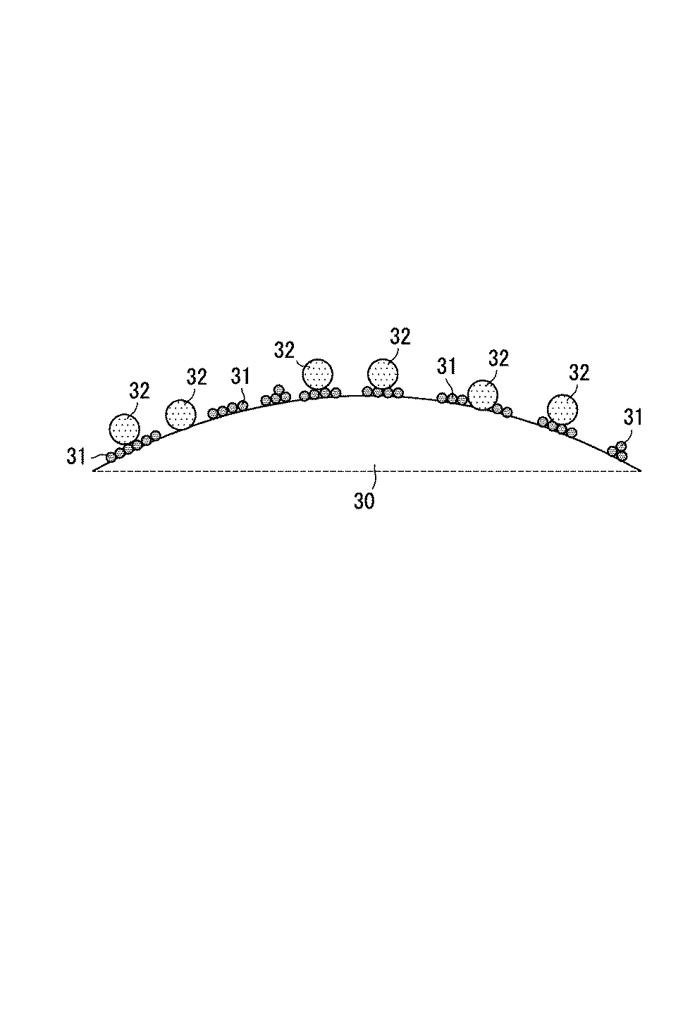
図3に、トナー粒子の表面構造の一例を示す。図3に示されるトナー粒子は、トナー母粒子30と、トナー母粒子30の表面に付着した外添剤(無機粒子31及び樹脂粒子32)とを備える。無機粒子31は、例えばシリカ粒子であってもよい。
FIG. 3 shows an example of the surface structure of the toner particles. The toner particles shown in FIG. 3 include
上記基本構成を有するトナーでは、無機粒子(外添剤)の遊離率が5%以下であり、樹脂粒子(外添剤)の遊離率が10%以上30%以下であり、樹脂粒子(外添剤)の個数平均1次粒子径が70nm以上200nm以下である。こうした構成により、無機粒子の脱離に先立って、樹脂粒子をトナー粒子から遊離させて、クリーニングブレードのエッジ部に溜めることが可能になる。例えば、図4に示すように、感光体ドラム12の表面Fにおいて、クリーニングブレード23のエッジ部E(先端部)に樹脂粒子32を溜めることで、感光体ドラム12上の付着物をクリーニングブレード23のエッジ部Eで堰き止めることが可能になる。クリーニングブレード23のエッジ部Eに適量の樹脂粒子32が存在することで、感光体ドラム12上の付着物(特に、無機粒子)が感光体ドラム12の表面Fとクリーニングブレード23のエッジ部Eとの間をすり抜けにくくなる。感光体ドラム12上の付着物が感光体ドラム12の表面Fとクリーニングブレード23のエッジ部Eとの間をすり抜けると、帯電性部材21(例えば、帯電ローラー)が汚染され易くなる。また、樹脂粒子(外添剤)の個数平均1次粒子径が小さ過ぎる場合には、トナー粒子間で樹脂粒子がスペーサーとして十分に機能しなくなり、トナーの耐ストレス性が不十分になり易くなる。他方、樹脂粒子(外添剤)の個数平均1次粒子径が大き過ぎる場合には、トナーの流動性が悪くなったり、クリーニングブレードのエッジ部に溜まった樹脂粒子により感光体(例えば、感光体ドラムの感光層)が削られ易くなったりする。樹脂粒子の粒子径は、例えば樹脂合成時の重合条件(特に、攪拌条件)に基づいて調整できる。上記基本構成を有するトナーでは、例えば無機粒子(外添剤)の個数平均1次粒子径が5nm以上50nm以下である場合にも、クリーニングブレードのエッジ部における無機粒子のすり抜けを好適に抑制することができると考えられる。
In the toner having the above basic structure, the liberation rate of the inorganic particles (external additive) is 5% or less, the liberation rate of the resin particles (external additive) is 10% or more and 30% or less, and the resin particles (external additive) The number average primary particle diameter of the agent is 70 nm or more and 200 nm or less. With this configuration, it is possible to release the resin particles from the toner particles and store them on the edge of the cleaning blade prior to the removal of the inorganic particles. For example, as shown in FIG. 4, the
帯電装置の汚染を抑制するためには、無機粒子(外添剤)の遊離率は小さいほど好ましく、下限値は限定されない。無機粒子の遊離率は0%であってもよい。ただし、生産性の観点からは、無機粒子の遊離率は1%以上であることが好ましい。また、樹脂粒子(外添剤)の遊離率が高過ぎると、帯電装置の汚染が生じ易くなる。外添剤(無機粒子又は樹脂粒子)の遊離率は、外添条件(例えば、外添時間)を変えることで調整できる。 In order to suppress the contamination of the charging device, the smaller the release rate of the inorganic particles (external additives), the better, and the lower limit value is not limited. The liberation rate of the inorganic particles may be 0%. However, from the viewpoint of productivity, the liberation rate of the inorganic particles is preferably 1% or more. On the other hand, when the liberation rate of the resin particles (external additive) is too high, the charging device is easily contaminated. The liberation rate of the external additive (inorganic particles or resin particles) can be adjusted by changing external addition conditions (for example, external addition time).
樹脂粒子(外添剤)のブロッキング率が45質量%を超えると、感光体汚染(感光体ドラムへの外添剤の付着)及びキャリア汚染(キャリアへの外添剤の付着)が発生し易くなる傾向がある。また、樹脂粒子の硬度(詳しくは、熱圧縮されにくさ)が高くなるほど、樹脂粒子のブロッキング率が低くなる傾向がある。樹脂粒子のブロッキング率を45質量%以下にするためには、樹脂粒子の硬度を非常に高い硬度にする必要があると考えられる。発明者は、高純度の架橋剤を使用することで、樹脂粒子のブロッキング率を45質量%以下にすることに成功した。例えば、ジビニルベンゼンを架橋剤として使用する場合、一般的には、純度(質量分率)50%程度のジビニルベンゼンが使用されているが、純度80%のジビニルベンゼンを使用することで、樹脂粒子のブロッキング率を45質量%以下にすることに成功した。 If the blocking rate of the resin particles (external additive) exceeds 45% by mass, photoconductor contamination (external additive adhesion to the photosensitive drum) and carrier contamination (external additive adhesion to the carrier) are likely to occur. Tend to be. Moreover, the blocking rate of the resin particles tends to decrease as the hardness of the resin particles (specifically, difficulty in thermal compression) increases. In order to make the blocking rate of the resin particles 45% by mass or less, it is considered that the hardness of the resin particles needs to be very high. The inventor succeeded in reducing the blocking rate of the resin particles to 45% by mass or less by using a high-purity crosslinking agent. For example, when divinylbenzene is used as a crosslinking agent, divinylbenzene having a purity (mass fraction) of about 50% is generally used, but resin particles can be obtained by using divinylbenzene having a purity of 80%. Successfully achieved a blocking rate of 45% by mass or less.
ただし、樹脂粒子(外添剤)の硬度を高くし過ぎると、樹脂粒子のブロッキング率が20質量%未満になると考えられる。樹脂粒子のブロッキング率が20質量%未満である場合、クリーニングブレードのエッジ部に溜まった樹脂粒子により感光体(例えば、感光体ドラムの感光層)が削られ易くなり、感光体ドラムの寿命が短くなる。樹脂粒子のブロッキング率は、例えば樹脂合成時の架橋剤の添加量を変えることで調整できる。 However, if the hardness of the resin particles (external additive) is too high, the blocking rate of the resin particles is considered to be less than 20% by mass. When the blocking rate of the resin particles is less than 20% by mass, the photosensitive member (for example, the photosensitive layer of the photosensitive drum) is easily scraped by the resin particles accumulated at the edge of the cleaning blade, and the life of the photosensitive drum is shortened. Become. The blocking rate of the resin particles can be adjusted, for example, by changing the amount of the crosslinking agent added during resin synthesis.
なお、前述の基本構成を有する画像形成装置は、タッチダウン画像形成装置に限られず、前述の基本構成により上記効果を奏すると考えられる。 Note that the image forming apparatus having the above-described basic configuration is not limited to the touch-down image forming apparatus, and it is considered that the above-described basic configuration provides the above effects.
無機粒子及び樹脂粒子の各々の遊離率を前述の基本構成で規定される範囲内にするためには、樹脂粒子(外添剤)の個数平均1次粒子径が、無機粒子(外添剤)の個数平均1次粒子径よりも大きいことが好ましい。 In order to make the liberation rate of each of the inorganic particles and the resin particles within the range defined by the above basic configuration, the number average primary particle diameter of the resin particles (external additive) is set to the inorganic particles (external additive). It is preferable that the number average primary particle diameter is larger.
無機粒子及び樹脂粒子の各々の遊離率を前述の基本構成で規定される範囲内にするためには、無機粒子及び樹脂粒子が、トナー母粒子の表面から、無機粒子、樹脂粒子の順の積層構造を有することが好ましい。以下、図3を参照して、トナー母粒子の表面において、上記積層構造(下層:無機粒子、上層:樹脂粒子)を有する無機粒子及び樹脂粒子の一例について説明する。 In order to make the liberation rate of each of the inorganic particles and the resin particles within the range defined by the above basic configuration, the inorganic particles and the resin particles are laminated in order of the inorganic particles and the resin particles from the surface of the toner base particles. It preferably has a structure. Hereinafter, an example of inorganic particles and resin particles having the above-described laminated structure (lower layer: inorganic particles, upper layer: resin particles) on the surface of the toner base particles will be described with reference to FIG.
図3に示されるトナー母粒子30の表面には、無機粒子31(例えば、シリカ粒子)及び樹脂粒子32が存在する。無機粒子31及び樹脂粒子32は、トナー母粒子30側から、無機粒子31、樹脂粒子32の順に積層された積層構造を有する。すなわち、無機粒子31は樹脂粒子32よりもトナー母粒子30側に位置する。無機粒子31は、トナー母粒子30の表面に付着している。樹脂粒子32は、無機粒子31の表面(ただし、トナー母粒子30の表面領域のうち無機粒子31が存在しない領域においては、トナー母粒子30の表面)に付着している。
Inorganic particles 31 (for example, silica particles) and
初期トナーに含まれるトナー粒子は、トナー母粒子がシェル層を備えないトナー粒子(以下、非カプセルトナー粒子と記載する)であってもよいし、トナー母粒子がシェル層を備えるトナー粒子(以下、カプセルトナー粒子と記載する)であってもよい。非カプセルトナー粒子のトナー母粒子(トナーコア)の表面にシェル層を形成することで、カプセルトナー粒子を製造することができる。シェル層は、実質的に熱硬化性樹脂(例えば、後述する「好適な熱硬化性樹脂」)のみからなってもよいし、実質的に熱可塑性樹脂(例えば、後述する「好適な熱可塑性樹脂」)のみからなってもよいし、熱可塑性樹脂と熱硬化性樹脂との両方を含有してもよい。 The toner particles contained in the initial toner may be toner particles in which the toner base particles do not have a shell layer (hereinafter referred to as non-capsule toner particles), or toner particles in which the toner base particles have a shell layer (hereinafter referred to as non-capsule toner particles). May be described as capsule toner particles). Capsule toner particles can be produced by forming a shell layer on the surface of toner base particles (toner core) of non-capsule toner particles. The shell layer may be substantially composed of only a thermosetting resin (for example, a “preferable thermosetting resin” described later), or substantially a thermoplastic resin (for example, a “preferable thermoplastic resin described later). ]) Or may contain both a thermoplastic resin and a thermosetting resin.
非カプセルトナー粒子は、例えば粉砕法又は凝集法により作製できる。これらの方法は、非カプセルトナー粒子の結着樹脂中に内添剤を良好に分散させ易い。 Non-capsule toner particles can be produced, for example, by a pulverization method or an aggregation method. In these methods, the internal additive is easily dispersed well in the binder resin of the non-capsule toner particles.
粉砕法の一例では、まず、結着樹脂、着色剤、電荷制御剤、及び離型剤を混合する。続けて、得られた混合物を、溶融混練装置(例えば、1軸又は2軸の押出機)を用いて溶融混練する。続けて、得られた溶融混練物を粉砕及び分級する。これにより、トナー母粒子が得られる。粉砕法を用いた場合には、凝集法を用いた場合よりも容易にトナー母粒子を作製できることが多い。 In an example of the pulverization method, first, a binder resin, a colorant, a charge control agent, and a release agent are mixed. Subsequently, the obtained mixture is melt-kneaded using a melt-kneading apparatus (for example, a single-screw or twin-screw extruder). Subsequently, the obtained melt-kneaded product is pulverized and classified. Thereby, toner mother particles are obtained. When the pulverization method is used, the toner base particles can often be produced more easily than when the aggregation method is used.
凝集法の一例では、まず、結着樹脂、離型剤、電荷制御剤、及び着色剤の各々の微粒子を含む水性媒体中で、これらの微粒子を所望の粒子径になるまで凝集させる。これにより、結着樹脂、離型剤、電荷制御剤、及び着色剤を含む凝集粒子が形成される。続けて、得られた凝集粒子を加熱して、凝集粒子に含まれる成分を合一化させる。これにより、所望の粒子径を有するトナー母粒子が得られる。 In an example of the aggregation method, first, these fine particles are aggregated in an aqueous medium containing fine particles of a binder resin, a release agent, a charge control agent, and a colorant until a desired particle size is obtained. Thereby, aggregated particles containing a binder resin, a release agent, a charge control agent, and a colorant are formed. Subsequently, the obtained aggregated particles are heated to unite the components contained in the aggregated particles. Thereby, toner mother particles having a desired particle diameter are obtained.
カプセルトナー粒子を製造する場合、シェル層の形成方法は任意である。例えば、in−situ重合法、液中硬化被膜法、及びコアセルベーション法のいずれかの方法を用いて、シェル層を形成してもよい。 When producing the capsule toner particles, the method for forming the shell layer is arbitrary. For example, the shell layer may be formed using any one of an in-situ polymerization method, a submerged cured coating method, and a coacervation method.
トナー粒子及びキャリア粒子の各々を構成する樹脂の好適な例を以下に示す。 Preferred examples of the resin constituting each of the toner particles and carrier particles are shown below.
<好適な熱可塑性樹脂>
熱可塑性樹脂の好適な例としては、スチレン系樹脂、アクリル酸系樹脂(より具体的には、アクリル酸エステル重合体又はメタクリル酸エステル重合体等)、オレフィン系樹脂(より具体的には、ポリエチレン樹脂又はポリプロピレン樹脂等)、塩化ビニル樹脂、ポリビニルアルコール、ビニルエーテル樹脂、N−ビニル樹脂、ポリエステル樹脂、ポリアミド樹脂、又はウレタン樹脂が挙げられる。また、これら各樹脂の共重合体、すなわち上記樹脂中に任意の繰返し単位が導入された共重合体(より具体的には、スチレン−アクリル酸系樹脂又はスチレン−ブタジエン系樹脂等)を使用してもよい。
<Preferable thermoplastic resin>
Suitable examples of thermoplastic resins include styrene resins, acrylic resins (more specifically, acrylic ester polymers or methacrylic ester polymers), olefin resins (more specifically, polyethylene). Resin or polypropylene resin), vinyl chloride resin, polyvinyl alcohol, vinyl ether resin, N-vinyl resin, polyester resin, polyamide resin, or urethane resin. Further, a copolymer of each of these resins, that is, a copolymer in which an arbitrary repeating unit is introduced into the resin (specifically, a styrene-acrylic acid resin or a styrene-butadiene resin) is used. May be.
熱可塑性樹脂は、1種以上の熱可塑性モノマーを、付加重合、共重合、又は縮重合させることで得られる。なお、熱可塑性モノマーは、単独重合により熱可塑性樹脂になるモノマー(より具体的には、アクリル酸系モノマー又はスチレン系モノマー等)、又は縮重合により熱可塑性樹脂になるモノマー(例えば、縮重合によりポリエステル樹脂になる多価アルコール及び多価カルボン酸の組合せ)である。 The thermoplastic resin can be obtained by addition polymerization, copolymerization, or condensation polymerization of one or more thermoplastic monomers. The thermoplastic monomer is a monomer that becomes a thermoplastic resin by homopolymerization (more specifically, an acrylic acid monomer or a styrene monomer), or a monomer that becomes a thermoplastic resin by condensation polymerization (for example, by condensation polymerization). A combination of a polyhydric alcohol and a polyhydric carboxylic acid to be a polyester resin.
スチレン−アクリル酸系樹脂は、1種以上のスチレン系モノマーと1種以上のアクリル酸系モノマーとの共重合体である。スチレン−アクリル酸系樹脂を合成するためには、例えば以下に示すような、スチレン系モノマー及びアクリル酸系モノマーを好適に使用できる。 The styrene-acrylic acid resin is a copolymer of one or more styrene monomers and one or more acrylic monomers. In order to synthesize a styrene-acrylic acid resin, for example, a styrene monomer and an acrylic acid monomer as shown below can be suitably used.
スチレン系モノマーの好適な例としては、スチレン、アルキルスチレン(より具体的には、α−メチルスチレン、p−エチルスチレン、又は4−tert−ブチルスチレン等)、p−ヒドロキシスチレン、m−ヒドロキシスチレン、ビニルトルエン、α−クロロスチレン、o−クロロスチレン、m−クロロスチレン、又はp−クロロスチレンが挙げられる。 Preferable examples of the styrene monomer include styrene, alkyl styrene (more specifically, α-methyl styrene, p-ethyl styrene, 4-tert-butyl styrene, etc.), p-hydroxy styrene, m-hydroxy styrene. , Vinyl toluene, α-chlorostyrene, o-chlorostyrene, m-chlorostyrene, or p-chlorostyrene.
アクリル酸系モノマーの好適な例としては、(メタ)アクリル酸、(メタ)アクリロニトリル、(メタ)アクリル酸アルキルエステル、又は(メタ)アクリル酸ヒドロキシアルキルエステルが挙げられる。(メタ)アクリル酸アルキルエステルの好適な例としては、(メタ)アクリル酸メチル、(メタ)アクリル酸エチル、(メタ)アクリル酸n−プロピル、(メタ)アクリル酸iso−プロピル、(メタ)アクリル酸n−ブチル、(メタ)アクリル酸iso−ブチル、又は(メタ)アクリル酸2−エチルヘキシルが挙げられる。(メタ)アクリル酸ヒドロキシアルキルエステルの好適な例としては、(メタ)アクリル酸2−ヒドロキシエチル、(メタ)アクリル酸3−ヒドロキシプロピル、(メタ)アクリル酸2−ヒドロキシプロピル、又は(メタ)アクリル酸4−ヒドロキシブチルが挙げられる。 Preferable examples of the acrylic acid monomer include (meth) acrylic acid, (meth) acrylonitrile, (meth) acrylic acid alkyl ester, or (meth) acrylic acid hydroxyalkyl ester. Suitable examples of the (meth) acrylic acid alkyl ester include methyl (meth) acrylate, ethyl (meth) acrylate, n-propyl (meth) acrylate, iso-propyl (meth) acrylate, and (meth) acrylic. Examples include n-butyl acid, iso-butyl (meth) acrylate, or 2-ethylhexyl (meth) acrylate. Suitable examples of the (meth) acrylic acid hydroxyalkyl ester include 2-hydroxyethyl (meth) acrylate, 3-hydroxypropyl (meth) acrylate, 2-hydroxypropyl (meth) acrylate, or (meth) acrylic. The acid 4-hydroxybutyl is mentioned.
ポリエステル樹脂は、1種以上の多価アルコールと1種以上の多価カルボン酸とを縮重合させることで得られる。ポリエステル樹脂を合成するためのアルコールとしては、例えば以下に示すような、2価アルコール(より具体的には、ジオール類又はビスフェノール類等)又は3価以上のアルコールを好適に使用できる。ポリエステル樹脂を合成するためのカルボン酸としては、例えば以下に示すような、2価カルボン酸又は3価以上のカルボン酸を好適に使用できる。 The polyester resin is obtained by polycondensation of one or more polyhydric alcohols and one or more polyhydric carboxylic acids. As the alcohol for synthesizing the polyester resin, for example, dihydric alcohols (more specifically, diols or bisphenols) as shown below or trihydric or higher alcohols can be suitably used. As the carboxylic acid for synthesizing the polyester resin, for example, divalent carboxylic acids or trivalent or higher carboxylic acids as shown below can be suitably used.
ジオール類の好適な例としては、エチレングリコール、ジエチレングリコール、トリエチレングリコール、1,2−プロパンジオール、1,3−プロパンジオール、1,4−ブタンジオール、ネオペンチルグリコール、1,4−ブテンジオール、1,5−ペンタンジオール、1,6−ヘキサンジオール、1,4−シクロヘキサンジメタノール、ジ1,2−プロパンジオール、ポリエチレングリコール、ポリ1,2−プロパンジオール、又はポリテトラメチレングリコールが挙げられる。 Suitable examples of diols include ethylene glycol, diethylene glycol, triethylene glycol, 1,2-propanediol, 1,3-propanediol, 1,4-butanediol, neopentyl glycol, 1,4-butenediol, Examples include 1,5-pentanediol, 1,6-hexanediol, 1,4-cyclohexanedimethanol, di1,2-propanediol, polyethylene glycol, poly1,2-propanediol, or polytetramethylene glycol.
ビスフェノール類の好適な例としては、ビスフェノールA、水素添加ビスフェノールA、ビスフェノールAエチレンオキサイド付加物、又はビスフェノールAプロピレンオキサイド付加物が挙げられる。 Preferable examples of the bisphenol include bisphenol A, hydrogenated bisphenol A, bisphenol A ethylene oxide adduct, or bisphenol A propylene oxide adduct.
3価以上のアルコールの好適な例としては、ソルビトール、1,2,3,6−ヘキサンテトロール、1,4−ソルビタン、ペンタエリスリトール、ジペンタエリスリトール、トリペンタエリスリトール、1,2,4−ブタントリオール、1,2,5−ペンタントリオール、グリセロール、ジグリセロール、2−メチルプロパントリオール、2−メチル−1,2,4−ブタントリオール、トリメチロールエタン、トリメチロールプロパン、又は1,3,5−トリヒドロキシメチルベンゼンが挙げられる。 Preferable examples of trihydric or higher alcohols include sorbitol, 1,2,3,6-hexanetetrol, 1,4-sorbitan, pentaerythritol, dipentaerythritol, tripentaerythritol, 1,2,4-butane. Triol, 1,2,5-pentanetriol, glycerol, diglycerol, 2-methylpropanetriol, 2-methyl-1,2,4-butanetriol, trimethylolethane, trimethylolpropane, or 1,3,5- Trihydroxymethylbenzene is mentioned.
2価カルボン酸の好適な例としては、マレイン酸、フマル酸、シトラコン酸、イタコン酸、グルタコン酸、フタル酸、イソフタル酸、テレフタル酸、シクロヘキサンジカルボン酸、アジピン酸、セバシン酸、アゼライン酸、マロン酸、コハク酸、アルキルコハク酸(より具体的には、n−ブチルコハク酸、イソブチルコハク酸、n−オクチルコハク酸、n−ドデシルコハク酸、又はイソドデシルコハク酸等)、又はアルケニルコハク酸(より具体的には、n−ブテニルコハク酸、イソブテニルコハク酸、n−オクテニルコハク酸、n−ドデセニルコハク酸、又はイソドデセニルコハク酸等)が挙げられる。 As preferable examples of the divalent carboxylic acid, maleic acid, fumaric acid, citraconic acid, itaconic acid, glutaconic acid, phthalic acid, isophthalic acid, terephthalic acid, cyclohexanedicarboxylic acid, adipic acid, sebacic acid, azelaic acid, malonic acid Succinic acid, alkyl succinic acid (more specifically, n-butyl succinic acid, isobutyl succinic acid, n-octyl succinic acid, n-dodecyl succinic acid, isododecyl succinic acid, etc.), or alkenyl succinic acid (more specific Specifically, n-butenyl succinic acid, isobutenyl succinic acid, n-octenyl succinic acid, n-dodecenyl succinic acid, or isododecenyl succinic acid, etc.) may be mentioned.
3価以上のカルボン酸の好適な例としては、1,2,4−ベンゼントリカルボン酸(トリメリット酸)、2,5,7−ナフタレントリカルボン酸、1,2,4−ナフタレントリカルボン酸、1,2,4−ブタントリカルボン酸、1,2,5−ヘキサントリカルボン酸、1,3−ジカルボキシル−2−メチル−2−メチレンカルボキシプロパン、1,2,4−シクロヘキサントリカルボン酸、テトラ(メチレンカルボキシル)メタン、1,2,7,8−オクタンテトラカルボン酸、ピロメリット酸、又はエンポール三量体酸が挙げられる。 Preferred examples of the trivalent or higher carboxylic acid include 1,2,4-benzenetricarboxylic acid (trimellitic acid), 2,5,7-naphthalenetricarboxylic acid, 1,2,4-naphthalenetricarboxylic acid, 2,4-butanetricarboxylic acid, 1,2,5-hexanetricarboxylic acid, 1,3-dicarboxyl-2-methyl-2-methylenecarboxypropane, 1,2,4-cyclohexanetricarboxylic acid, tetra (methylenecarboxyl) Examples include methane, 1,2,7,8-octanetetracarboxylic acid, pyromellitic acid, or empole trimer acid.
<好適な熱硬化性樹脂>
熱硬化性樹脂の好適な例としては、メラミン系樹脂、尿素系樹脂、スルホンアミド系樹脂、グリオキザール系樹脂、グアナミン系樹脂、アニリン系樹脂、ポリイミド樹脂(より具体的には、マレイミド重合体又はビスマレイミド重合体等)、キシレン系樹脂、又はエポキシ樹脂が挙げられる。
<Preferable thermosetting resin>
Preferred examples of the thermosetting resin include melamine resin, urea resin, sulfonamide resin, glyoxal resin, guanamine resin, aniline resin, polyimide resin (more specifically, maleimide polymer or bismuth resin). Maleimide polymer, etc.), xylene-based resin, or epoxy resin.
熱硬化性樹脂は、1種以上の熱硬化性モノマーを架橋反応(重合)させることで得られる。また、架橋剤を用いることで、熱可塑性モノマーにより熱硬化性樹脂を合成することもできる。なお、熱硬化性モノマーは、架橋性を有するモノマーである。例えば、同種のモノマー同士が「−CH2−」を介して3次元的につながって熱硬化性樹脂になる場合、そのモノマーは「熱硬化性モノマー」に相当する。 The thermosetting resin can be obtained by crosslinking (polymerizing) one or more thermosetting monomers. Moreover, a thermosetting resin can also be synthesize | combined with a thermoplastic monomer by using a crosslinking agent. The thermosetting monomer is a monomer having crosslinkability. For example, when monomers of the same kind are three-dimensionally connected via “—CH 2 —” to become a thermosetting resin, the monomer corresponds to a “thermosetting monomer”.
熱硬化性モノマーの好適な例としては、メチロールメラミン、メラミン、メチロール化尿素(より具体的には、ジメチロールジヒドロキシエチレン尿素等)、尿素、ベンゾグアナミン、アセトグアナミン、又はスピログアナミンが挙げられる。 Preferable examples of the thermosetting monomer include methylol melamine, melamine, methylolated urea (more specifically, dimethylol dihydroxyethylene urea), urea, benzoguanamine, acetoguanamine, or spiroguanamine.
次に、非カプセルトナー粒子及びキャリア粒子の各々の構成の好適な例について説明する。 Next, preferred examples of the configuration of each of the non-capsule toner particles and the carrier particles will be described.
[トナー母粒子]
トナー母粒子は、結着樹脂を含有する。また、トナー母粒子は、内添剤(例えば、着色剤、離型剤、電荷制御剤、及び磁性粉)を含有してもよい。
[Toner mother particles]
The toner base particles contain a binder resin. The toner base particles may contain an internal additive (for example, a colorant, a release agent, a charge control agent, and a magnetic powder).
(結着樹脂)
トナー母粒子では、一般的に、成分の大部分(例えば、85質量%以上)を結着樹脂が占める。このため、結着樹脂の性質がトナー母粒子の全体の性質に大きな影響を与えると考えられる。トナーの耐熱保存性及び低温定着性の両立を図るためには、トナー母粒子が、結着樹脂として、前述の「好適な熱可塑性樹脂」を含有することが好ましく、ポリエステル樹脂及びスチレン−アクリル酸系樹脂の少なくとも一方を含有することが特に好ましい。トナーの帯電安定性を向上させるためには、トナー母粒子が、結着樹脂として、酸価5mgKOH/g以上20mgKOH/g以下のポリエステル樹脂を含有することが特に好ましい。
(Binder resin)
In the toner base particles, generally, the binder resin occupies most of the components (for example, 85% by mass or more). For this reason, it is considered that the properties of the binder resin greatly affect the overall properties of the toner base particles. In order to achieve both the heat-resistant storage stability and the low-temperature fixability of the toner, the toner base particles preferably contain the above-mentioned “suitable thermoplastic resin” as the binder resin. The polyester resin and the styrene-acrylic acid are preferable. It is particularly preferable to contain at least one of the resin. In order to improve the charging stability of the toner, it is particularly preferable that the toner base particles contain a polyester resin having an acid value of 5 mgKOH / g or more and 20 mgKOH / g or less as a binder resin.
(着色剤)
トナー母粒子は、着色剤を含有してもよい。着色剤としては、トナーの色に合わせて公知の顔料又は染料を用いることができる。トナーを用いて高画質の画像を形成するためには、着色剤の量が、結着樹脂100質量部に対して、1質量部以上20質量部以下であることが好ましい。
(Coloring agent)
The toner base particles may contain a colorant. As the colorant, a known pigment or dye can be used according to the color of the toner. In order to form a high-quality image using toner, the amount of the colorant is preferably 1 part by mass or more and 20 parts by mass or less with respect to 100 parts by mass of the binder resin.
トナー母粒子は、黒色着色剤を含有していてもよい。黒色着色剤の例としては、カーボンブラックが挙げられる。また、黒色着色剤は、イエロー着色剤、マゼンタ着色剤、及びシアン着色剤を用いて黒色に調色された着色剤であってもよい。 The toner base particles may contain a black colorant. An example of a black colorant is carbon black. The black colorant may be a colorant that is toned to black using a yellow colorant, a magenta colorant, and a cyan colorant.
トナー母粒子は、イエロー着色剤、マゼンタ着色剤、又はシアン着色剤のようなカラー着色剤を含有していてもよい。 The toner base particles may contain a color colorant such as a yellow colorant, a magenta colorant, or a cyan colorant.
イエロー着色剤としては、例えば、縮合アゾ化合物、イソインドリノン化合物、アントラキノン化合物、アゾ金属錯体、メチン化合物、及びアリールアミド化合物からなる群より選択される1種以上の化合物を使用できる。イエロー着色剤としては、例えば、C.I.ピグメントイエロー(3、12、13、14、15、17、62、74、83、93、94、95、97、109、110、111、120、127、128、129、147、151、154、155、168、174、175、176、180、181、191、又は194)、ナフトールイエローS、ハンザイエローG、又はC.I.バットイエローを好適に使用できる。 As the yellow colorant, for example, one or more compounds selected from the group consisting of condensed azo compounds, isoindolinone compounds, anthraquinone compounds, azo metal complexes, methine compounds, and arylamide compounds can be used. Examples of the yellow colorant include C.I. I. Pigment Yellow (3, 12, 13, 14, 15, 17, 62, 74, 83, 93, 94, 95, 97, 109, 110, 111, 120, 127, 128, 129, 147, 151, 154, 155 168, 174, 175, 176, 180, 181, 191, or 194), naphthol yellow S, Hansa yellow G, or C.I. I. Vat yellow can be preferably used.
マゼンタ着色剤としては、例えば、縮合アゾ化合物、ジケトピロロピロール化合物、アントラキノン化合物、キナクリドン化合物、塩基染料レーキ化合物、ナフトール化合物、ベンズイミダゾロン化合物、チオインジゴ化合物、及びペリレン化合物からなる群より選択される1種以上の化合物を使用できる。マゼンタ着色剤としては、例えば、C.I.ピグメントレッド(2、3、5、6、7、19、23、48:2、48:3、48:4、57:1、81:1、122、144、146、150、166、169、177、184、185、202、206、220、221、又は254)を好適に使用できる。 The magenta colorant is, for example, selected from the group consisting of condensed azo compounds, diketopyrrolopyrrole compounds, anthraquinone compounds, quinacridone compounds, basic dye lake compounds, naphthol compounds, benzimidazolone compounds, thioindigo compounds, and perylene compounds. One or more compounds can be used. Examples of the magenta colorant include C.I. I. Pigment Red (2, 3, 5, 6, 7, 19, 23, 48: 2, 48: 3, 48: 4, 57: 1, 81: 1, 122, 144, 146, 150, 166, 169, 177 184, 185, 202, 206, 220, 221 or 254) can be preferably used.
シアン着色剤としては、例えば、銅フタロシアニン化合物、アントラキノン化合物、及び塩基染料レーキ化合物からなる群より選択される1種以上の化合物を使用できる。シアン着色剤としては、例えば、C.I.ピグメントブルー(1、7、15、15:1、15:2、15:3、15:4、60、62、又は66)、フタロシアニンブルー、C.I.バットブルー、又はC.I.アシッドブルーを好適に使用できる。 As the cyan colorant, for example, one or more compounds selected from the group consisting of a copper phthalocyanine compound, an anthraquinone compound, and a basic dye lake compound can be used. Examples of cyan colorants include C.I. I. Pigment blue (1, 7, 15, 15: 1, 15: 2, 15: 3, 15: 4, 60, 62, or 66), phthalocyanine blue, C.I. I. Bat Blue, or C.I. I. Acid blue can be preferably used.
(離型剤)
トナー母粒子は、離型剤を含有していてもよい。離型剤は、例えば、トナーの定着性又は耐オフセット性を向上させる目的で使用される。トナーの定着性又は耐オフセット性を向上させるためには、離型剤の量は、結着樹脂100質量部に対して、1質量部以上30質量部以下であることが好ましい。
(Release agent)
The toner base particles may contain a release agent. The release agent is used, for example, for the purpose of improving the fixing property or offset resistance of the toner. In order to improve the fixing property or offset resistance of the toner, the amount of the release agent is preferably 1 part by mass or more and 30 parts by mass or less with respect to 100 parts by mass of the binder resin.
離型剤としては、例えば、低分子量ポリエチレン、低分子量ポリプロピレン、ポリオレフィン共重合物、ポリオレフィンワックス、マイクロクリスタリンワックス、パラフィンワックス、又はフィッシャートロプシュワックスのような脂肪族炭化水素ワックス;酸化ポリエチレンワックス又はそのブロック共重合体のような脂肪族炭化水素ワックスの酸化物;キャンデリラワックス、カルナバワックス、木ろう、ホホバろう、又はライスワックスのような植物性ワックス;みつろう、ラノリン、又は鯨ろうのような動物性ワックス;オゾケライト、セレシン、又はペトロラタムのような鉱物ワックス;モンタン酸エステルワックス又はカスターワックスのような脂肪酸エステルを主成分とするワックス類;脱酸カルナバワックスのような、脂肪酸エステルの一部又は全部が脱酸化したワックスを好適に使用できる。1種類の離型剤を単独で使用してもよいし、複数種の離型剤を併用してもよい。 Examples of the release agent include low molecular weight polyethylene, low molecular weight polypropylene, polyolefin copolymer, polyolefin wax, microcrystalline wax, paraffin wax, or aliphatic hydrocarbon wax such as Fischer-Tropsch wax; oxidized polyethylene wax or a block thereof Oxides of aliphatic hydrocarbon waxes such as copolymers; plant waxes such as candelilla wax, carnauba wax, wood wax, jojoba wax, or rice wax; animal properties such as beeswax, lanolin, or whale wax Waxes; mineral waxes such as ozokerite, ceresin, or petrolatum; waxes based on fatty acid esters such as montanate ester wax or castor wax; fats such as deoxidized carnauba wax The wax portion of the ester or the whole was deoxygenated can be suitably used. One type of release agent may be used alone, or multiple types of release agents may be used in combination.
(電荷制御剤)
トナー母粒子は、電荷制御剤を含有していてもよい。電荷制御剤は、例えば、トナーの帯電安定性又は帯電立ち上がり特性を向上させる目的で使用される。トナーの帯電立ち上がり特性は、短時間で所定の帯電レベルにトナーを帯電可能か否かの指標になる。
(Charge control agent)
The toner base particles may contain a charge control agent. The charge control agent is used, for example, for the purpose of improving the charge stability or charge rising property of the toner. The charge rising characteristic of the toner is an index as to whether or not the toner can be charged to a predetermined charge level in a short time.
トナー母粒子に正帯電性の電荷制御剤(より具体的には、ピリジン、ニグロシン、又は4級アンモニウム塩等)を含有させることで、トナー母粒子のカチオン性を強めることができる。ただし、トナーにおいて十分な帯電性が確保される場合には、トナー母粒子に電荷制御剤を含有させる必要はない。 By adding a positively chargeable charge control agent (more specifically, pyridine, nigrosine, quaternary ammonium salt, or the like) to the toner base particles, the cationicity of the toner base particles can be increased. However, if sufficient chargeability is ensured in the toner, it is not necessary to add a charge control agent to the toner base particles.
(磁性粉)
トナー母粒子は、磁性粉を含有していてもよい。磁性粉の材料としては、例えば、強磁性金属(より具体的には、鉄、コバルト、ニッケル、又はこれら金属の1種以上を含む合金等)、強磁性金属酸化物(より具体的には、フェライト、マグネタイト、又は二酸化クロム等)、又は強磁性化処理が施された材料(より具体的には、熱処理により強磁性が付与された炭素材料等)を好適に使用できる。磁性粉からの金属イオン(例えば、鉄イオン)の溶出を抑制するためには、表面処理された磁性粒子を磁性粉として使用することが好ましい。1種類の磁性粉を単独で使用してもよいし、複数種の磁性粉を併用してもよい。
(Magnetic powder)
The toner base particles may contain magnetic powder. Examples of magnetic powder materials include ferromagnetic metals (more specifically, iron, cobalt, nickel, or alloys containing one or more of these metals), ferromagnetic metal oxides (more specifically, Ferrite, magnetite, chromium dioxide, or the like) or a material subjected to ferromagnetization treatment (more specifically, a carbon material or the like imparted with ferromagnetism by heat treatment) can be suitably used. In order to suppress elution of metal ions (for example, iron ions) from the magnetic powder, it is preferable to use the surface-treated magnetic particles as the magnetic powder. One type of magnetic powder may be used alone, or a plurality of types of magnetic powder may be used in combination.
[外添剤]
トナー母粒子の表面には外添剤(詳しくは、複数の外添剤粒子を含む粉体)が付着している。詳しくは、トナー粒子は、外添剤として無機粒子及び樹脂粒子を備える。例えば、トナー母粒子(粉体)と外添剤(粉体)とを一緒に攪拌することで、物理的な力でトナー母粒子の表面に外添剤が付着(物理的結合)する。
[External additive]
An external additive (specifically, a powder containing a plurality of external additive particles) adheres to the surface of the toner base particles. Specifically, the toner particles include inorganic particles and resin particles as external additives. For example, the toner base particles (powder) and the external additive (powder) are stirred together, so that the external additive adheres (physically bonds) to the surface of the toner base particles with a physical force.
無機粒子(外添剤)としては、シリカ粒子、又は金属酸化物(より具体的には、アルミナ、チタニア(酸化チタン)、酸化マグネシウム、酸化亜鉛、チタン酸ストロンチウム、又はチタン酸バリウム等)の粒子が好ましく、シリカ粒子及びチタニア粒子からなる群より選択される1種以上の粒子が特に好ましい。 As inorganic particles (external additives), particles of silica particles or metal oxides (more specifically, alumina, titania (titanium oxide), magnesium oxide, zinc oxide, strontium titanate, barium titanate, etc.) Are preferable, and one or more kinds of particles selected from the group consisting of silica particles and titania particles are particularly preferable.
樹脂粒子(外添剤)としては、架橋アクリル酸系樹脂及び架橋スチレン−アクリル酸系樹脂からなる群より選択される1種以上の樹脂を含有する樹脂粒子が好ましく、架橋スチレン−アクリル酸系樹脂粒子が特に好ましい。架橋アクリル酸系樹脂及び架橋スチレン−アクリル酸系樹脂はそれぞれ、帯電性に優れ、メラミン樹脂等と比べて、微粒子を作製し易い。 The resin particles (external additives) are preferably resin particles containing one or more resins selected from the group consisting of a crosslinked acrylic resin and a crosslinked styrene-acrylic resin, and the crosslinked styrene-acrylic resin. Particles are particularly preferred. The cross-linked acrylic acid resin and the cross-linked styrene-acrylic acid resin each have excellent chargeability and are easier to produce fine particles than melamine resins and the like.
外添剤粒子は、表面処理されていてもよい。例えば、外添剤粒子としてシリカ粒子を使用する場合、表面処理剤によりシリカ粒子の表面に疎水性及び/又は正帯電性が付与されていてもよい。表面処理剤としては、例えば、カップリング剤(より具体的には、シランカップリング剤、チタネートカップリング剤、又はアルミネートカップリング剤等)、又はシリコーンオイル(より具体的には、ジメチルシリコーンオイル等)を好適に使用できる。シランカップリング剤として、シラン化合物(より具体的には、メチルトリメトキシシラン、又はアミノシラン等)を使用してもよいし、シラザン化合物(より具体的には、HMDS(ヘキサメチルジシラザン)等)を使用してもよい。シリカ粒子の表面が表面処理剤で処理されると、シリカ粒子の表面に存在する多数の水酸基(−OH)が部分的に又は全体的に、表面処理剤に由来する官能基に置換される。その結果、表面処理剤に由来する官能基(詳しくは、水酸基よりも疎水性及び/又は正帯電性の強い官能基)を表面に有するシリカ粒子が得られる。例えば、アミノ基を有するシランカップリング剤を用いてシリカ粒子の表面を処理した場合、シランカップリング剤の水酸基(例えば、水分によりシランカップリング剤のアルコキシ基が加水分解されて生成する水酸基)がシリカ粒子の表面に存在する水酸基と脱水縮合反応(「A(シリカ粒子)−OH」+「B(カップリング剤)−OH」→「A−O−B」+H2O)する。こうした反応により、アミノ基を有するシランカップリング剤とシリカ粒子とが化学結合することで、シリカ粒子の表面にアミノ基が付与される。より詳しくは、シリカ粒子の表面に存在する水酸基が、端部にアミノ基を有する官能基(より具体的には、−O−Si−(CH2)3−NH2等)に置換される。アミノ基が付与されたシリカ粒子は、未処理のシリカ粒子よりも強い正帯電性を有する傾向がある。また、アルキル基を有するシランカップリング剤を用いた場合には、上記脱水縮合反応により、シリカ粒子の表面に存在する水酸基を、端部にアルキル基を有する官能基(より具体的には、−O−Si−CH3等)に置換することができる。このように、親水性基(水酸基)の代わりに疎水性基(アルキル基)が付与されたシリカ粒子は、未処理のシリカ粒子よりも強い疎水性を有する傾向がある。 The external additive particles may be surface-treated. For example, when silica particles are used as the external additive particles, hydrophobicity and / or positive chargeability may be imparted to the surface of the silica particles by the surface treatment agent. Examples of the surface treatment agent include a coupling agent (more specifically, a silane coupling agent, a titanate coupling agent, or an aluminate coupling agent), or silicone oil (more specifically, dimethyl silicone oil). Etc.) can be suitably used. As the silane coupling agent, a silane compound (more specifically, methyltrimethoxysilane, aminosilane or the like) may be used, or a silazane compound (more specifically, HMDS (hexamethyldisilazane) or the like). May be used. When the surface of the silica particles is treated with the surface treatment agent, a large number of hydroxyl groups (—OH) present on the surface of the silica particles are partially or entirely substituted with functional groups derived from the surface treatment agent. As a result, silica particles having a functional group derived from the surface treating agent (specifically, a functional group that is more hydrophobic and / or positively charged than the hydroxyl group) on the surface can be obtained. For example, when the surface of the silica particles is treated with a silane coupling agent having an amino group, the hydroxyl group of the silane coupling agent (for example, a hydroxyl group generated by hydrolysis of the alkoxy group of the silane coupling agent with moisture) A dehydration condensation reaction (“A (silica particle) —OH” + “B (coupling agent) —OH” → “AO—B” + H 2 O) occurs with a hydroxyl group present on the surface of the silica particle. By such a reaction, the amino group is imparted to the surface of the silica particle by chemically bonding the silane coupling agent having an amino group and the silica particle. More specifically, the hydroxyl group present on the surface of the silica particles is substituted with a functional group having an amino group at the end (more specifically, —O—Si— (CH 2 ) 3 —NH 2 or the like). Silica particles provided with amino groups tend to have a stronger positive charge than untreated silica particles. When a silane coupling agent having an alkyl group is used, a hydroxyl group present on the surface of the silica particle is converted into a functional group having an alkyl group at the end (more specifically, − it can be replaced by O-Si-CH 3, etc.). Thus, the silica particle to which the hydrophobic group (alkyl group) was provided instead of the hydrophilic group (hydroxyl group) tends to have stronger hydrophobicity than the untreated silica particle.
[キャリア粒子]
キャリア粒子は、コート層を備えないキャリア粒子(例えば、フェライトキャリア粒子)であってもよいし、コート層を備えるキャリア粒子(以下、被覆キャリア粒子と記載する)であってもよい。現像剤を用いて長期にわたって高画質の画像を形成するためには、被覆キャリア粒子を使用することが好ましい。被覆キャリア粒子は、キャリアコアと、キャリアコアの表面を覆うコート層とを備える。コート層は、キャリアコアの表面全域を覆っていてもよいし、キャリアコアの表面を部分的に覆っていてもよい。
[Carrier particles]
The carrier particles may be carrier particles without a coat layer (for example, ferrite carrier particles), or may be carrier particles with a coat layer (hereinafter referred to as coated carrier particles). In order to form a high-quality image over a long period of time using a developer, it is preferable to use coated carrier particles. The coated carrier particles include a carrier core and a coat layer that covers the surface of the carrier core. The coat layer may cover the entire surface of the carrier core, or may partially cover the surface of the carrier core.
以下、被覆キャリア粒子の好適な例について説明する。被覆キャリア粒子は、キャリアコア及びコート層を備える。なお、下記構成を有するキャリアコアを、コート層で覆わずに、そのままキャリア粒子として使用してもよい。 Hereinafter, suitable examples of the coated carrier particles will be described. The coated carrier particle includes a carrier core and a coat layer. In addition, you may use the carrier core which has the following structure as carrier particles as it is, without covering with a coating layer.
(キャリアコア)
キャリアコアは、磁性材料を含有することが好ましい。キャリアコアが磁性材料の粒子であってもよいし、キャリアコアの結着樹脂中に磁性材料の粒子を分散させてもよい。キャリアコアに含有される磁性材料としては、例えば、マグネタイト、バリウムフェライト、マグヘマイト、Mn−Znフェライト、Ni−Znフェライト、Mn−Mgフェライト、Ca−Mgフェライト、Liフェライト、又はCu−Znフェライトのような金属酸化物が好ましく、マグネタイトが特に好ましい。個々のキャリアコアの材料として、1種類の磁性材料を単独で使用してもよいし、2種以上の磁性材料を併用してもよい。キャリアコアとしては、市販品を使用してもよい。また、磁性材料を粉砕及び焼成してキャリアコアを自作してもよい。キャリアコアの作製において、磁性材料の添加量(特に、強磁性材料の割合)を変えることで、キャリアの飽和磁化を調整することができる。また、キャリアコアの作製において、焼成温度を変えることで、キャリアの円形度を調整することができる。
(Career core)
The carrier core preferably contains a magnetic material. The carrier core may be magnetic material particles, or the magnetic material particles may be dispersed in the binder resin of the carrier core. Examples of the magnetic material contained in the carrier core include magnetite, barium ferrite, maghemite, Mn—Zn ferrite, Ni—Zn ferrite, Mn—Mg ferrite, Ca—Mg ferrite, Li ferrite, and Cu—Zn ferrite. Metal oxides are preferred, and magnetite is particularly preferred. As a material for each carrier core, one type of magnetic material may be used alone, or two or more types of magnetic materials may be used in combination. A commercially available product may be used as the carrier core. Also, the carrier core may be made by pulverizing and firing the magnetic material. In the production of the carrier core, the saturation magnetization of the carrier can be adjusted by changing the amount of magnetic material added (particularly, the proportion of the ferromagnetic material). Further, in the production of the carrier core, the circularity of the carrier can be adjusted by changing the firing temperature.
(コート層)
コート層は、キャリアコアを被覆するように、キャリアコアの表面に形成される。コート層は、実質的に樹脂から構成される。コート層を構成する樹脂中に添加剤が分散していてもよい。コート層の形成方法の例としては、樹脂(又は、樹脂の材料)を含む液にキャリアコアを浸漬する方法、又は、樹脂(又は、樹脂の材料)を含む液を流動層中のキャリアコアに噴霧する方法が挙げられる。
(Coat layer)
The coat layer is formed on the surface of the carrier core so as to cover the carrier core. The coat layer is substantially composed of a resin. Additives may be dispersed in the resin constituting the coat layer. Examples of the method for forming the coat layer include a method of immersing the carrier core in a liquid containing a resin (or resin material), or a liquid containing a resin (or resin material) in the carrier core in the fluidized bed. The method of spraying is mentioned.
キャリアの耐久性を向上させるためには、キャリアコアを覆う樹脂(被覆樹脂)の量が0.5質量%以上5.0質量%以下であることが好ましい。なお、被覆樹脂の量(単位:質量%)は、式「被覆樹脂の量=100×被覆樹脂の質量/キャリアコアの質量と被覆樹脂の質量との合計」で表される。また、キャリアの耐久性を向上させるためには、コート層が、キャリアコアの表面領域のうち、90%以上の面積を覆っていることが好ましく、100%の面積を覆っていることがより好ましい。 In order to improve the durability of the carrier, the amount of resin (coating resin) covering the carrier core is preferably 0.5% by mass or more and 5.0% by mass or less. The amount (unit: mass%) of the coating resin is represented by the formula “amount of coating resin = 100 × the mass of the coating resin / the total of the mass of the carrier core and the coating resin”. In order to improve the durability of the carrier, the coat layer preferably covers 90% or more of the surface area of the carrier core, and more preferably covers 100% of the area. .
コート層を構成する樹脂としては、熱可塑性樹脂(より具体的には、前述した「好適な熱可塑性樹脂」、又はフッ素樹脂等)を使用してもよいし、熱硬化性樹脂(より具体的には、前述した「好適な熱硬化性樹脂」、又はシリコーン樹脂等)を使用してもよい。また、熱可塑性モノマーと硬化剤とを混合することにより、熱可塑性樹脂に架橋性を付与してもよい。コート層は海島構造を有していてもよい。 As the resin constituting the coat layer, a thermoplastic resin (more specifically, the “preferable thermoplastic resin” described above, or a fluororesin) may be used, or a thermosetting resin (more specifically, The above-mentioned “preferable thermosetting resin” or silicone resin may be used. Moreover, you may provide crosslinking | crosslinked property to a thermoplastic resin by mixing a thermoplastic monomer and a hardening | curing agent. The coat layer may have a sea-island structure.
キャリア粒子の付着性(付着し易さ)を低下させるためには、コート層がフッ素樹脂を含有することが好ましい。また、コート層が、ポリアミドイミド樹脂(PAI)及びポリイミド樹脂(PI)からなる群より選択される1種以上の樹脂と、フッ素樹脂とを含有する場合、コート層全体に対してフッ素樹脂の含有量は50質量%以上90質量%以下であることが好ましい。フッ素樹脂の含有量(単位:質量%)は、式「フッ素樹脂の含有量=100×コート層中のフッ素樹脂の質量/コート層全体の質量」で表される。フッ素樹脂の含有量が少な過ぎると、キャリアの帯電付与性が不十分になり易い。また、フッ素樹脂の含有量が多過ぎると、コート層からフッ素樹脂粒子が過剰に遊離したり、コート層中にフッ素樹脂が分散しにくくなったりする。コート層に含有されるフッ素樹脂としては、ポリフッ化ビニル、ポリフッ化ビニリデン、ポリテトラフルオロエチレン(PTFE)、ポリトリフルオロエチレン(より具体的には、ポリクロロトリフルオロエチレン等)、ポリヘキサフルオロプロピレン、テトラフルオロエチレン−ヘキサフルオロプロピレン共重合体(FEP)、及びテトラフルオロエチレン−パーフルオロアルキルビニルエーテル共重合体(PFA)からなる群より選択される1種以上の樹脂が好ましく、FEP又はPFAが特に好ましい。 In order to reduce the adhesion (easy to adhere) of the carrier particles, the coat layer preferably contains a fluororesin. In addition, when the coat layer contains one or more resins selected from the group consisting of polyamideimide resin (PAI) and polyimide resin (PI), and a fluororesin, the content of the fluororesin relative to the entire coat layer The amount is preferably 50% by mass or more and 90% by mass or less. The content (unit: mass%) of the fluororesin is represented by the formula “content of fluororesin = 100 × mass of fluororesin in the coat layer / mass of the entire coat layer”. If the content of the fluororesin is too small, the charge imparting property of the carrier tends to be insufficient. Moreover, when there is too much content of a fluororesin, a fluororesin particle | grain will liberate too much from a coating layer, or it will become difficult to disperse | distribute a fluororesin in a coating layer. Examples of the fluororesin contained in the coating layer include polyvinyl fluoride, polyvinylidene fluoride, polytetrafluoroethylene (PTFE), polytrifluoroethylene (more specifically, polychlorotrifluoroethylene, etc.), polyhexafluoropropylene. One or more resins selected from the group consisting of tetrafluoroethylene-hexafluoropropylene copolymer (FEP) and tetrafluoroethylene-perfluoroalkyl vinyl ether copolymer (PFA) are preferred, and FEP or PFA is particularly preferred preferable.
本発明の実施例について説明する。表1に、実施例又は比較例に係る装置D−1〜D−14(それぞれ画像形成装置)、並びに各装置で使用されているトナーTA−1〜TA−5及びTB−1〜TB−9を示す。また、表2には、表1に示される各トナーの製造に用いられる外添剤(樹脂粒子A−1〜A−4及びB−1〜B−4)を示す。 Examples of the present invention will be described. Table 1 shows apparatuses D-1 to D-14 (image forming apparatuses) according to Examples or Comparative Examples, and toners TA-1 to TA-5 and TB-1 to TB-9 used in each apparatus. Indicates. Table 2 shows external additives (resin particles A-1 to A-4 and B-1 to B-4) used in the production of the toners shown in Table 1.
以下、装置D−1〜D−14の製造方法、評価方法、及び評価結果について、順に説明する。なお、誤差が生じる評価においては、誤差が十分小さくなる相当数の測定値を得て、得られた測定値の算術平均を評価値とした。また、樹脂粒子及び無機粒子の各々の個数平均1次粒子径の測定には、走査型電子顕微鏡(SEM)を用いた。 Hereinafter, a manufacturing method, an evaluation method, and an evaluation result of the devices D-1 to D-14 will be described in order. In the evaluation in which an error occurs, a considerable number of measurement values with sufficiently small errors are obtained, and the arithmetic average of the obtained measurement values is used as the evaluation value. A scanning electron microscope (SEM) was used to measure the number average primary particle size of each of the resin particles and inorganic particles.
[材料の準備]
(樹脂粒子A−1〜A−4の調製)
攪拌装置、冷却管、温度計、及び窒素導入管を備えた容量1Lの4つ口フラスコ内に、イオン交換水600gと、乳化剤(DBS:ドデシルベンゼンスルホン酸ナトリウム)6gと、メタクリル酸n−ブチル(BMA)100gと、スチレン20gと、開始剤(BPO:ベンゾイルパーオキサイド)15gと、表2に示す量の架橋剤(DVB:ジビニルベンゼン)とを入れた。例えば、樹脂粒子A−1の調製では、架橋剤(ジビニルベンゼン)を70g添加した。また、樹脂粒子A−2の調製では、架橋剤(ジビニルベンゼン)を20g添加した。また、樹脂粒子A−3の調製では、架橋剤(ジビニルベンゼン)を18g添加した。また、樹脂粒子A−4の調製では、架橋剤(ジビニルベンゼン)を85g添加した。架橋剤として使用したジビニルベンゼン(DVB)の純度(質量分率)は80%であった。
[Preparation of materials]
(Preparation of resin particles A-1 to A-4)
In a 4-liter flask having a capacity of 1 L equipped with a stirrer, a cooling tube, a thermometer, and a nitrogen introduction tube, 600 g of ion-exchanged water, 6 g of emulsifier (DBS: sodium dodecylbenzenesulfonate), and n-butyl methacrylate 100 g of (BMA), 20 g of styrene, 15 g of an initiator (BPO: benzoyl peroxide), and an amount of a crosslinking agent (DVB: divinylbenzene) shown in Table 2 were added. For example, in the preparation of the resin particle A-1, 70 g of a crosslinking agent (divinylbenzene) was added. Further, in the preparation of the resin particle A-2, 20 g of a crosslinking agent (divinylbenzene) was added. Moreover, in preparation of resin particle A-3, 18 g of a crosslinking agent (divinylbenzene) was added. Moreover, 85 g of a crosslinking agent (divinylbenzene) was added in the preparation of the resin particles A-4. The purity (mass fraction) of divinylbenzene (DVB) used as a crosslinking agent was 80%.
続けて、フラスコ内容物を攪拌しながら、フラスコ内に窒素ガスを導入して、フラスコ内を窒素雰囲気にした。さらに、フラスコ内容物を攪拌しながら、窒素雰囲気でフラスコ内容物の温度を90℃に上昇させて、窒素雰囲気かつ温度90℃の条件でフラスコ内容物を3時間反応(詳しくは、重合反応)させた。その結果、個数平均1次粒子径90nmの反応生成物を含むエマルションが得られた。続けて、得られたエマルションを冷却し、洗浄工程及び脱水工程を経て、個数平均1次粒子径90nmの樹脂粒子A−1〜A−4を得た。 Subsequently, while stirring the contents of the flask, nitrogen gas was introduced into the flask to create a nitrogen atmosphere inside the flask. Further, while stirring the flask contents, the temperature of the flask contents is increased to 90 ° C. in a nitrogen atmosphere, and the flask contents are reacted for 3 hours (specifically, a polymerization reaction) in a nitrogen atmosphere and a temperature of 90 ° C. It was. As a result, an emulsion containing a reaction product having a number average primary particle diameter of 90 nm was obtained. Subsequently, the obtained emulsion was cooled, and resin particles A-1 to A-4 having a number average primary particle size of 90 nm were obtained through a washing step and a dehydrating step.
(樹脂粒子B−1〜B−4の調製)
反応生成物の個数平均1次粒子径が表2に示す値(B−1:70nm、B−2:200nm、B−3:60nm、B−4:220nm)になるように、前述の重合反応時間(樹脂粒子A−1では、3時間)を変更した以外は樹脂粒子A−1の調製方法と同様にして、樹脂粒子B−1〜B−4を得た。なお、重合反応時間を長くするほど反応生成物(ひいては、樹脂粒子)の粒子径が大きくなる傾向がある。
(Preparation of resin particles B-1 to B-4)
The polymerization reaction described above so that the number average primary particle size of the reaction product is the value shown in Table 2 (B-1: 70 nm, B-2: 200 nm, B-3: 60 nm, B-4: 220 nm). Resin particles B-1 to B-4 were obtained in the same manner as the method for preparing the resin particles A-1, except that the time (3 hours for the resin particles A-1) was changed. In addition, there exists a tendency for the particle diameter of a reaction product (and resin particle) to become large, so that polymerization reaction time is lengthened.
上記のようにして得られた樹脂粒子A−1〜A−4及びB−1〜B−4に関して、ブロッキング率(詳しくは、温度160℃かつ圧力0.1kgf/mm2での5分間加圧後、目開き75μmのメッシュにより測定されるブロッキング率)の測定結果は、表2に示すとおりであった。例えば、樹脂粒子A−1のブロッキング率は20%であった。ブロッキング率の測定方法は、次に示すとおりであった。 With respect to the resin particles A-1 to A-4 and B-1 to B-4 obtained as described above, the blocking rate (specifically, pressurization for 5 minutes at a temperature of 160 ° C. and a pressure of 0.1 kgf / mm 2 was performed. Thereafter, the measurement results of the blocking rate measured with a mesh having an opening of 75 μm were as shown in Table 2. For example, the blocking rate of the resin particle A-1 was 20%. The method for measuring the blocking rate was as follows.
<ブロッキング率の測定方法>
測定用治具として、円柱状の穴(直径:10mm、深さ:10mm)が形成された台(材質:オーステナイトステンレス鋼)と、円柱状の圧子(直径:10mm、材質:オーステナイトステンレス鋼)と、ヒーターとを備える装置(京セラドキュメントソリューションズ株式会社製)を使用した。
<Measurement method of blocking rate>
As a measuring jig, a base (material: austenitic stainless steel) with a cylindrical hole (diameter: 10 mm, depth: 10 mm) and a cylindrical indenter (diameter: 10 mm, material: austenitic stainless steel) And an apparatus (manufactured by Kyocera Document Solutions Co., Ltd.) equipped with a heater.
温度23℃及び湿度50%RHの環境下において、治具の穴(測定部位)に、測定対象としての樹脂粒子(樹脂粒子A−1〜A−4及びB−1〜B−4のいずれか)10mgを投入した。治具のヒーターで測定部位を160℃に加熱し、治具の圧子(荷重:約100N)で測定部位(樹脂粒子)に0.1kgf/mm2の圧力を5分間加えた。その後、測定部位(穴の中)にある樹脂粒子を全量回収し、質量既知の目開き75μmの篩(JIS Z8801−1で規定される200メッシュ)上にセットした。そして、樹脂粒子を含む篩の質量を測定し、篩上の樹脂粒子の質量(吸引前の樹脂粒子の質量)を求めた。 Under an environment of a temperature of 23 ° C. and a humidity of 50% RH, resin particles (resin particles A-1 to A-4 and B-1 to B-4 as measurement objects) are placed in a hole (measurement site) of a jig. ) 10 mg was charged. The measurement site was heated to 160 ° C. with a jig heater, and a pressure of 0.1 kgf / mm 2 was applied to the measurement site (resin particles) with a jig indenter (load: about 100 N) for 5 minutes. Thereafter, the entire amount of the resin particles at the measurement site (in the hole) was collected and set on a sieve (200 mesh defined by JIS Z8801-1) having a mesh size of 75 μm. And the mass of the sieve containing resin particles was measured, and the mass of resin particles on the sieve (the mass of resin particles before suction) was determined.
続けて、吸引機(アマノ株式会社製「V−3SDR」)を用いて、篩の下方から篩上の樹脂粒子を吸引した。この吸引により、篩上の樹脂粒子のうちブロッキングしていない樹脂粒子のみが篩を通過した。吸引後、篩を通過しなかった樹脂粒子(篩上に残留した樹脂粒子)の質量を測定した。そして、吸引前の樹脂粒子の質量と、吸引後の樹脂粒子の質量(篩を通過しなかった樹脂粒子の質量)とに基づいて、次の式に従ってブロッキング率(単位:質量%)を求めた。
ブロッキング率=100×吸引後の樹脂粒子の質量/吸引前の樹脂粒子の質量
Subsequently, using a suction machine (“V-3SDR” manufactured by Amano Co., Ltd.), resin particles on the sieve were sucked from the lower side of the sieve. By this suction, only non-blocking resin particles out of the resin particles on the sieve passed through the sieve. After the suction, the mass of the resin particles that did not pass through the sieve (resin particles remaining on the sieve) was measured. Based on the mass of the resin particles before suction and the mass of the resin particles after suction (the mass of the resin particles that did not pass through the sieve), the blocking rate (unit: mass%) was determined according to the following formula. .
Blocking rate = 100 × mass of resin particles after suction / mass of resin particles before suction
[トナーの製造]
(トナー母粒子の作製)
FMミキサー(日本コークス工業株式会社製)を用いて、ポリエステル樹脂(酸価:5.6mgKOH/g、軟化点(Tm):105℃)100質量部と、着色剤(C.I.ピグメントブルー15:3、成分:銅フタロシアニン顔料)4質量部と、4級アンモニウム塩(オリヱント化学工業株式会社製「BONTRON(登録商標)P−51」)1質量部と、エステルワックス(日油株式会社製「ニッサンエレクトール(登録商標)WEP−3」、溶融温度:73℃)5質量部とを混合した。
[Production of toner]
(Preparation of toner base particles)
Using an FM mixer (Nihon Coke Kogyo Co., Ltd.), 100 parts by mass of a polyester resin (acid value: 5.6 mg KOH / g, softening point (Tm): 105 ° C.) and a colorant (CI Pigment Blue 15) : 3, component: copper phthalocyanine pigment) 4 parts by mass, quaternary ammonium salt ("BONTRON (registered trademark) P-51" manufactured by Orient Chemical Co., Ltd.) 1 part by mass, ester wax (manufactured by NOF Corporation " Nissan Electol (registered trademark) WEP-3 ”, melting temperature: 73 ° C.) and 5 parts by mass were mixed.
続けて、得られた混合物を、2軸押出機(株式会社池貝製「PCM−30」)を用いて溶融混練した。続けて、得られた混練物を冷却した後、粉砕機(フロイント・ターボ株式会社製「ターボミル」)を用いて粉砕した。続けて、得られた粉砕物を、分級機(日鉄鉱業株式会社製「エルボージェットEJ−LABO型」)を用いて分級した。その結果、体積中位径(D50)6.8μmのトナー母粒子が得られた。 Subsequently, the obtained mixture was melt-kneaded using a twin-screw extruder (“PCM-30” manufactured by Ikegai Co., Ltd.). Subsequently, the obtained kneaded product was cooled and then pulverized using a pulverizer (“Turbo Mill” manufactured by Freund Turbo). Subsequently, the obtained pulverized product was classified using a classifier (“Elbow Jet EJ-LABO type” manufactured by Nippon Steel Mining Co., Ltd.). As a result, toner mother particles having a volume median diameter (D 50 ) of 6.8 μm were obtained.
(第1外添)
温度調節用のジャケットを備える容量10LのFMミキサー(日本コークス工業株式会社製)を用いて、ジャケットに温度20℃の水を循環させながら、前述の手順で作製したトナー母粒子100質量部と、表1に示す第1外添剤とを、所定の時間(各トナーに定められた、表1に示される時間)混合した。第1外添剤は、各トナーに定められた、表1に示されるシリカ粒子、チタニア粒子、樹脂粒子A−1、及びコロイダルシリカ粒子のいずれかであった。第1外添剤の添加量は、トナーTA−5以外の製造では、トナー母粒子100質量部に対して1質量部であった。トナーTA−5の製造では、トナー母粒子100質量部に対してシリカ粒子0.8質量部及びチタニア粒子0.4質量部を添加した。このタイミングでの混合が、表1中の「第1外添」に相当する。第1外添により、トナー母粒子の表面に第1外添剤が付着した。
(First external addition)
Using a 10 L FM mixer (manufactured by Nihon Coke Kogyo Co., Ltd.) having a temperature control jacket, 100 parts by weight of toner base particles prepared in the above-described procedure while circulating water at a temperature of 20 ° C. through the jacket; The first external additive shown in Table 1 was mixed for a predetermined time (the time shown in Table 1 determined for each toner). The first external additive was any one of silica particles, titania particles, resin particles A-1, and colloidal silica particles shown in Table 1 defined for each toner. The amount of the first external additive added was 1 part by mass with respect to 100 parts by mass of the toner base particles in the manufacture other than the toner TA-5. In the production of toner TA-5, 0.8 part by mass of silica particles and 0.4 part by mass of titania particles were added to 100 parts by mass of toner base particles. The mixing at this timing corresponds to the “first external addition” in Table 1. The first external additive adhered to the surface of the toner base particles by the first external addition.
例えば、トナーTA−1の製造では、FMミキサーを用いてトナー母粒子100質量部とシリカ粒子1質量部とを15分間混合した。また、トナーTA−5の製造では、FMミキサーを用いてトナー母粒子100質量部とシリカ粒子0.8質量部とチタニア粒子0.4質量部とを15分間混合した。また、トナーTB−3の製造では、FMミキサーを用いてトナー母粒子100質量部と樹脂粒子(前述の手順で調製した樹脂粒子A−1)1質量部とを5分間混合した。また、トナーTB−8の製造では、FMミキサーを用いてトナー母粒子100質量部と個数平均1次粒子径100nmのコロイダルシリカ粒子1質量部とを15分間混合した。シリカ粒子としては、正帯電性シリカ粒子(日本アエロジル株式会社製「AEROSIL(登録商標)RA200」、内容:表面処理により疎水性及び正帯電性が付与された乾式シリカ粒子、表面処理剤:ヘキサメチルジシラザン(HMDS)及びアミノシラン、個数平均1次粒子径:約12nm)を使用した。チタニア粒子としては、親水性チタニア粒子(チタン工業株式会社製「STT−65C」、チタニア結晶型:アナターゼ、表面処理剤:トリエタノールアミン、個数平均1次粒子径:約40nm)を使用した。 For example, in the production of toner TA-1, 100 parts by mass of toner base particles and 1 part by mass of silica particles were mixed for 15 minutes using an FM mixer. In the production of the toner TA-5, 100 parts by mass of toner base particles, 0.8 parts by mass of silica particles, and 0.4 parts by mass of titania particles were mixed for 15 minutes using an FM mixer. In the production of toner TB-3, 100 parts by mass of toner base particles and 1 part by mass of resin particles (resin particles A-1 prepared by the above-described procedure) were mixed for 5 minutes using an FM mixer. In the production of the toner TB-8, 100 parts by mass of toner base particles and 1 part by mass of colloidal silica particles having a number average primary particle diameter of 100 nm were mixed for 15 minutes using an FM mixer. As the silica particles, positively-charged silica particles (“AEROSIL (registered trademark) RA200” manufactured by Nippon Aerosil Co., Ltd.), content: dry silica particles imparted with hydrophobicity and positive chargeability by surface treatment, surface treatment agent: hexamethyl Disilazane (HMDS) and aminosilane, number average primary particle size: about 12 nm) were used. As titania particles, hydrophilic titania particles (“STT-65C” manufactured by Titanium Industry Co., Ltd., titania crystal type: anatase, surface treatment agent: triethanolamine, number average primary particle size: about 40 nm) were used.
(第2外添)
続けて、上記FMミキサーに対して、表1に示す第2外添剤(各トナーに定められた、表1に示されるシリカ粒子、樹脂粒子A−1〜A−4及びB−1〜B−4、並びにコロイダルシリカ粒子のいずれか)1質量部をさらに投入した。例えば、トナーTA−1の製造では、FMミキサー内のトナー母粒子100質量部に対して1質量部の樹脂粒子(前述の手順で調製した樹脂粒子A−1)を投入した。また、トナーTB−3の製造では、FMミキサー内のトナー母粒子100質量部に対して1質量部のシリカ粒子を投入した。シリカ粒子としては、正帯電性シリカ粒子(AEROSIL RA200)を使用した。また、トナーTB−8の製造では、FMミキサー内のトナー母粒子100質量部に対して1質量部のコロイダルシリカ粒子(個数平均1次粒子径:100nm)を投入した。
(Second external addition)
Subsequently, for the FM mixer, the second external additive shown in Table 1 (silica particles, resin particles A-1 to A-4 and B-1 to B shown in Table 1 defined for each toner). -4 and any one of colloidal silica particles) 1 part by mass was further added. For example, in the production of the toner TA-1, 1 part by mass of resin particles (resin particle A-1 prepared by the above-described procedure) is added to 100 parts by mass of toner base particles in the FM mixer. In the production of the toner TB-3, 1 part by mass of silica particles was added to 100 parts by mass of the toner base particles in the FM mixer. As the silica particles, positively charged silica particles (AEROSIL RA200) were used. In the production of the toner TB-8, 1 part by mass of colloidal silica particles (number average primary particle size: 100 nm) was added to 100 parts by mass of the toner base particles in the FM mixer.
続けて、上記FMミキサーによる混合を、所定の時間(各トナーに定められた、表1に示される時間)行った。このタイミングでの混合が、表1中の「第2外添」に相当する。例えば、トナーTA−1の製造では、上記FMミキサーを用いて、表面に第1外添剤(シリカ粒子)が付着したトナー母粒子と、第2外添剤(樹脂粒子A−1)とを、さらに5分間混合した。第2外添により、第1外添剤が付着したトナー母粒子の表面に、第2外添剤がさらに付着した。 Subsequently, mixing by the FM mixer was performed for a predetermined time (the time shown in Table 1 determined for each toner). The mixing at this timing corresponds to the “second external addition” in Table 1. For example, in the production of the toner TA-1, using the FM mixer, the toner base particles having the first external additive (silica particles) attached to the surface and the second external additive (resin particles A-1) are used. For an additional 5 minutes. By the second external addition, the second external additive further adhered to the surface of the toner base particles to which the first external additive adhered.
その後、得られた粉体を、200メッシュ(目開き75μm)の篩を用いて篩別した。その結果、トナー粒子(非カプセルトナー粒子)を多数含むトナー(トナーTA−1〜TA−5及びTB−1〜TB−9)が得られた。 Thereafter, the obtained powder was sieved using a 200-mesh (aperture 75 μm) sieve. As a result, toners (toners TA-1 to TA-5 and TB-1 to TB-9) containing a large number of toner particles (non-capsule toner particles) were obtained.
上記のようにして得られたトナーTA−1〜TA−5及びTB−1〜TB−9に関して、外添剤(無機粒子及び樹脂粒子)の遊離率(詳しくは、超音波処理を5分間行った状態のトナー分散液について測定される遊離率)の測定結果は、表1に示すとおりであった。例えば、トナーTA−1では、無機粒子の遊離率が3%であり、樹脂粒子の遊離率が20%であった。遊離率の測定方法は、以下のとおりであった。 Regarding toners TA-1 to TA-5 and TB-1 to TB-9 obtained as described above, the liberation rate of external additives (inorganic particles and resin particles) (specifically, ultrasonic treatment is performed for 5 minutes) Table 1 shows the measurement results of the liberation rate measured for the toner dispersion in the same state. For example, in toner TA-1, the release rate of inorganic particles was 3%, and the release rate of resin particles was 20%. The method for measuring the liberation rate was as follows.
<遊離率の測定方法>
超音波処理を5分間行った状態のトナー分散液について、無機粒子及び樹脂粒子の各々の遊離率を測定した。詳しくは、トナー分散液を濾過して、トナー分散液中に遊離した無機粒子を除去した後、トナー分散液中に残ったトナー(以下、「超音波処理後試料」と記載する)について蛍光X線分析及びGC/MS分析をそれぞれ行い、蛍光X線スペクトル及びGC/MS法マススペクトルを得た。また、超音波処理後試料とは別に、超音波処理を施す前の試料(以下、「初期試料」と記載する)についても蛍光X線分析及びGC/MS分析をそれぞれ行い、蛍光X線スペクトル及びGC/MS法マススペクトルを得た。そして、超音波処理後試料の蛍光X線スペクトルと初期試料の蛍光X線スペクトルとを対比して、無機粒子の遊離率を求めた。また、超音波処理後試料のGC/MS法マススペクトルと初期試料のGC/MS法マススペクトルとを対比して、樹脂粒子の遊離率を求めた。上記超音波処理、蛍光X線分析、GC/MS分析、及び遊離率の求め方の詳細は、以下のとおりであった。
<Measurement method of liberation rate>
The release rate of each of the inorganic particles and the resin particles was measured for the toner dispersion in which the ultrasonic treatment was performed for 5 minutes. Specifically, after the toner dispersion is filtered to remove inorganic particles released in the toner dispersion, the toner remaining in the toner dispersion (hereinafter referred to as “sample after ultrasonic treatment”) is fluorescent X X-ray analysis and GC / MS analysis were performed to obtain a fluorescent X-ray spectrum and a GC / MS mass spectrum, respectively. Separately from the sample after sonication, a sample before sonication (hereinafter referred to as “initial sample”) is also subjected to X-ray fluorescence analysis and GC / MS analysis, respectively. A GC / MS mass spectrum was obtained. And the freezing rate of the inorganic particle was calculated | required by contrasting the fluorescence X-ray spectrum of the sample after ultrasonic treatment, and the fluorescence X-ray spectrum of an initial stage sample. Further, the GC / MS method mass spectrum of the sample after ultrasonic treatment was compared with the GC / MS method mass spectrum of the initial sample to obtain the release rate of the resin particles. Details of the ultrasonic treatment, fluorescent X-ray analysis, GC / MS analysis, and how to determine the liberation rate were as follows.
(超音波処理)
ノニオン界面活性剤(花王株式会社製「エマルゲン(登録商標)120」、成分:ポリオキシエチレンラウリルエーテル)の濃度2質量%水溶液100g中に試料(トナー)2.0gを分散させて、トナー分散液を得た。続けて、得られたトナー分散液に、超音波分散機(超音波工業株式会社製「ウルトラソニックミニウェルダーP128」、出力:100W、発振周波数:28kHz)を用いて超音波処理を5分間施した。続けて、定性ろ紙(アドバンテック社製「FILTER PAPER 1号」、孔径約5μm)をセットしたセパレート型の吸引濾過装置(濾過鐘及びブフナー漏斗)を用いて、上記のように超音波処理が施されたトナー分散液を吸引濾過した。その後、イオン交換水50mLを加えるリスラリーと、吸引濾過とを、3回繰り返して、トナー粒子の表面に付着した界面活性剤を除去した。
(Sonication)
Toner dispersion liquid was prepared by dispersing 2.0 g of a sample (toner) in 100 g of a 2% by weight aqueous solution of a nonionic surfactant (Emulgen (registered trademark) 120 manufactured by Kao Corporation, component: polyoxyethylene lauryl ether). Got. Subsequently, the obtained toner dispersion was subjected to ultrasonic treatment for 5 minutes using an ultrasonic disperser (“Ultrasonic Miniwelder P128” manufactured by Ultrasonic Industrial Co., Ltd., output: 100 W, oscillation frequency: 28 kHz). . Subsequently, using a separate type suction filtration device (filter bell and Buchner funnel) set with qualitative filter paper (“FILTER PAPER No. 1” manufactured by Advantech Co., Ltd., pore diameter of about 5 μm), ultrasonic treatment was performed as described above. The toner dispersion was suction filtered. Thereafter, reslurry to which 50 mL of ion exchange water was added and suction filtration were repeated three times to remove the surfactant attached to the surface of the toner particles.
その後、洗浄に使用したろ紙を、ろ紙上に残ったトナーごとアルミ皿(アルミニウム製容器)に移し、そのアルミ皿を真空定温乾燥機に入れて40℃で12時間真空乾燥した。その結果、超音波処理後試料が得られた。 Thereafter, the filter paper used for washing was transferred together with the toner remaining on the filter paper to an aluminum dish (aluminum container), and the aluminum dish was placed in a vacuum constant temperature dryer and vacuum dried at 40 ° C. for 12 hours. As a result, a sample after sonication was obtained.
(蛍光X線分析)
超音波処理後試料及び初期試料をそれぞれ測定対象とした。測定対象としてのトナー1.5gを、圧力20MPaかつ加圧時間3秒間の条件で加圧成形して、直径30mmの円柱状ペレットを作製した。続けて、得られたペレットについて蛍光X線分析を行い、検出対象(所定の元素)に由来するピークを含む蛍光X線スペクトル(横軸:エネルギー、縦軸:強度(光子の数))を得た。検出対象は、外添剤として使用した無機粒子中の特徴的な元素とした。例えば、外添剤としてシリカ粒子を使用した試料(トナー)については、Si(珪素)を検出対象として、下記条件で蛍光X線分析を行った。
・分析装置:走査型蛍光X線分析装置(株式会社リガク製「ZSX」)
・X線管球(X線源):Rh(ロジウム)
・励起条件:管電圧50kV、管電流50mA
・測定領域(X線照射範囲):直径30mm
・測定元素:Si(珪素)
(X-ray fluorescence analysis)
The sample after sonication and the initial sample were measured. 1.5 g of toner as a measurement object was pressure-molded under the conditions of a pressure of 20 MPa and a pressurization time of 3 seconds to produce a cylindrical pellet having a diameter of 30 mm. Subsequently, the obtained pellet is subjected to fluorescent X-ray analysis to obtain a fluorescent X-ray spectrum (horizontal axis: energy, vertical axis: intensity (number of photons)) including a peak derived from the detection target (predetermined element). It was. The detection target was a characteristic element in the inorganic particles used as the external additive. For example, a sample (toner) using silica particles as an external additive was subjected to fluorescent X-ray analysis under the following conditions using Si (silicon) as a detection target.
・ Analyzer: Scanning X-ray fluorescence analyzer (“ZSX” manufactured by Rigaku Corporation)
・ X-ray tube (X-ray source): Rh (Rhodium)
Excitation conditions: tube voltage 50 kV, tube current 50 mA
・ Measurement area (X-ray irradiation range): Diameter 30mm
・ Measurement element: Si (silicon)
(無機粒子の遊離率の求め方)
上記蛍光X線分析により超音波処理後試料及び初期試料の各々について得た蛍光X線スペクトルに基づいて、無機粒子(外添剤)の遊離率を算出した。詳しくは、超音波処理後試料の無機粒子由来ピーク強度XAと、初期試料の無機粒子由来ピーク強度XBとから、式「XT=100×(XB−XA)/XB」に従って無機粒子の遊離率XTを算出した。また、トナーTA−5では、超音波処理後試料のシリカ粒子由来ピーク強度XA1と、初期試料のシリカ粒子由来ピーク強度XB1と、超音波処理後試料のチタニア粒子由来ピーク強度XA2と、初期試料のチタニア粒子由来ピーク強度XB2とから、式「XT=100×{(XB1−XA1)+(XB2−XA2)}/(XB1+XB2)」に従って無機粒子の遊離率XTを算出した。
(How to find the release rate of inorganic particles)
Based on the fluorescent X-ray spectrum obtained for each of the sample after ultrasonication and the initial sample by the fluorescent X-ray analysis, the liberation rate of the inorganic particles (external additive) was calculated. Specifically, the derived inorganic particles peak intensity X A sample after sonication, an inorganic particle-derived peak intensity X B of the initial sample, according to the equation "X T = 100 × (X B -X A) / X B " It was calculated liberation percentage X T of the inorganic particles. In toner TA-5, silica particle-derived peak intensity X A1 of the sample after ultrasonic treatment, silica particle-derived peak intensity X B1 of the initial sample, titania particle-derived peak intensity X A2 of the sample after ultrasonic treatment, The release of inorganic particles from the titania particle-derived peak intensity X B2 of the initial sample according to the formula “X T = 100 × {(X B1 −X A1 ) + (X B2 −X A2 )} / (X B1 + X B2 )” The rate XT was calculated.
(GC/MS分析)
超音波処理後試料及び初期試料をそれぞれ測定対象とした。測定装置としては、ガスクロマトグラフ質量分析計(株式会社島津製作所製「GCMS−QP2010 Ultra」)及びマルチショット・パイロライザー(アジレント・テクノロジー社製「PY−3030D」)を用いた。カラムとしては、GCカラム(アジレント・テクノロジー社製「Agilent(登録商標)J&W ウルトライナートキャピラリGCカラム DB−5ms」、相:シロキサンポリマーにアリレンを入れてポリマーの主鎖を強化したアリレン相、内径:0.25mm、膜厚:0.25μm、長さ:30m)を用いた。測定対象としてのトナー100μgについて、以下の条件でGC/MS分析を行い、樹脂粒子(外添剤)に由来するピークを含むマススペクトル(横軸:イオンの質量/イオンの電荷数、縦軸:検出強度)を得た。
・熱分解温度:加熱炉「600℃」、インターフェイス部「320℃」
・昇温条件:40℃から速度28℃/分で320℃まで昇温し、320℃で5分間保持した。
・キャリアガス:ヘリウム(He)ガス(線速度36.1cm/分)
・カラムヘッド圧力:49.7kPa
・注入モード:スプリット注入(スプリット比1:200)
・キャリア流量:全流量「204mL/分」、カラム流量「1mL/分」、パージ流量「3mL/分」
(GC / MS analysis)
The sample after sonication and the initial sample were measured. As a measuring device, a gas chromatograph mass spectrometer (“GCMS-QP2010 Ultra” manufactured by Shimadzu Corporation) and a multi-shot pyrolyzer (“PY-3030D” manufactured by Agilent Technologies) were used. As a column, a GC column ("Agilent (registered trademark) J & W Ultra Inert Capillary GC Column DB-5ms" manufactured by Agilent Technologies, Inc.), phase: an arylene phase in which allylene is reinforced with a siloxane polymer to strengthen the main chain of the polymer, inner diameter: 0.25 mm, film thickness: 0.25 μm, length: 30 m). With respect to 100 μg of the toner to be measured, GC / MS analysis was performed under the following conditions, and a mass spectrum including peaks derived from resin particles (external additives) (horizontal axis: ion mass / ion charge number, vertical axis: Detection intensity) was obtained.
・ Pyrolysis temperature: Furnace “600 ° C”, interface part “320 ° C”
Temperature rising condition: The temperature was raised from 40 ° C. to 320 ° C. at a rate of 28 ° C./min and held at 320 ° C. for 5 minutes.
Carrier gas: Helium (He) gas (linear velocity 36.1 cm / min)
Column head pressure: 49.7 kPa
Injection mode: split injection (split ratio 1: 200)
Carrier flow rate: total flow rate “204 mL / min”, column flow rate “1 mL / min”, purge flow rate “3 mL / min”
(樹脂粒子の遊離率の求め方)
上記GC/MS分析により超音波処理後試料及び初期試料の各々について得たマススペクトル(GC/MS法マススペクトル)に基づいて、樹脂粒子(外添剤)の遊離率を算出した。詳しくは、超音波処理後試料の樹脂粒子由来ピーク面積YAと、初期試料の樹脂粒子由来ピーク面積YBとから、式「YT=100×(YB−YA)/YB」に従って樹脂粒子の遊離率YTを算出した。
(How to determine the release rate of resin particles)
The liberation rate of the resin particles (external additive) was calculated based on the mass spectrum (GC / MS method mass spectrum) obtained for each of the sample after sonication and the initial sample by the GC / MS analysis. Specifically, a resin particle-derived peak area Y A sample after sonication, a resin particle-derived peak area Y B of the initial sample, according to the equation "Y T = 100 × (Y B -Y A) / Y B " The release rate Y T of the resin particles was calculated.
[キャリアの製造]
MnO換算で39.7モル%、MgO換算で9.9モル%、Fe2O3換算で49.6モル%、SrO換算で0.8モル%になるように各原材料(MnO、MgO、Fe2O3、及びSrOの各原材料)を適量配合し、原材料に水を加えた。続けて、湿式ボールミルを用いて原材料を10時間かけて粉砕した後、混合した。続けて、得られた混合物を乾燥させた。続けて、乾燥した混合物に温度950℃の熱処理を4時間行った。
[Manufacture of carriers]
39.7 mol% in terms of MnO, 9.9 mol% in terms of MgO, 49.6 mol% calculated as Fe 2 O 3, each raw material (MnO to be 0.8 mol% in terms of SrO, MgO, Fe 2 O 3 and SrO raw materials) were mixed in appropriate amounts, and water was added to the raw materials. Subsequently, the raw materials were ground using a wet ball mill for 10 hours and then mixed. Subsequently, the resulting mixture was dried. Subsequently, the dried mixture was subjected to heat treatment at a temperature of 950 ° C. for 4 hours.
続けて、湿式ボールミルを用いて、上記熱処理後の混合物を24時間かけて粉砕して、スラリーを調製した。続けて、得られたスラリーの乾燥及び造粒を、スプレードライヤーで行った。続けて、乾燥した造粒物を、温度1270℃かつ酸素濃度2%の雰囲気中に6時間保持した後、解砕した。その後、粒度調整を行うことで、3000(103/4π・A/m)の印加磁場での飽和磁化が70Am2/kgであるMn−Mg−Srフェライト粒子(磁性キャリアコア)の粉体(個数平均1次粒子径:35μm)が得られた。 Subsequently, using a wet ball mill, the mixture after the heat treatment was pulverized over 24 hours to prepare a slurry. Subsequently, the resulting slurry was dried and granulated with a spray dryer. Subsequently, the dried granulated product was crushed after being held in an atmosphere at a temperature of 1270 ° C. and an oxygen concentration of 2% for 6 hours. Thereafter, by adjusting the particle size, powder of Mn—Mg—Sr ferrite particles (magnetic carrier core) having a saturation magnetization of 70 Am 2 / kg in an applied magnetic field of 3000 (10 3 / 4π · A / m) ( Number average primary particle size: 35 μm) was obtained.
続けて、ポリアミドイミド樹脂(無水トリメリット酸と4,4’−ジアミノジフェニルメタンとの共重合体)を水で希釈して、固形分濃度10質量%の樹脂溶液を調製した。続けて、得られた樹脂溶液中に、質量割合3ppmでペルフルオロオクタン酸を含有するPFA(テトラフルオロエチレン・パーフルオロアルキルビニルエーテル共重合体)と、ノニオン界面活性剤(ポリオキシエチレンアルキルエーテル)とを分散させて、キャリアコート液を得た。得られたキャリアコート液に関して、ポリアミドイミド樹脂とPFAとの質量比(ポリアミドイミド樹脂:PFA)は2:8であった。 Subsequently, a polyamideimide resin (copolymer of trimellitic anhydride and 4,4'-diaminodiphenylmethane) was diluted with water to prepare a resin solution having a solid content concentration of 10% by mass. Subsequently, PFA (tetrafluoroethylene / perfluoroalkyl vinyl ether copolymer) containing perfluorooctanoic acid at a mass ratio of 3 ppm and a nonionic surfactant (polyoxyethylene alkyl ether) are contained in the obtained resin solution. The carrier coating solution was obtained by dispersing. With respect to the obtained carrier coat liquid, the mass ratio of polyamideimide resin and PFA (polyamideimide resin: PFA) was 2: 8.
続けて、上記のようにして調製したキャリアコート液と、磁性キャリアコア(前述の手順で作製したMn−Mg−Srフェライト粒子の粉体)とを、転動流動コーティング装置(株式会社パウレック製「マルチプレックス」)に投入し、転動流動コーティング装置を用いて磁性キャリアコアをキャリアコート液で被覆した。続けて、樹脂で被覆された磁性キャリアコアを250℃で1時間焼成した。続けて、得られた焼成物を、冷却した後、解砕した。その結果、樹脂被覆量2質量%で磁性キャリアコアの表面がコート層(樹脂層)で被覆され、磁性キャリアコア(磁性材料:Mn−Mg−Srフェライト)とコート層(樹脂:ポリアミドイミド樹脂とPFAとの混合樹脂)とを備えるキャリア粒子を多数含むキャリアが得られた。なお、樹脂被覆量(単位:質量%)は、式「樹脂被覆量=100×被覆樹脂の質量/樹脂被覆フェライトキャリア全部の質量」で表される。 Subsequently, the carrier coat liquid prepared as described above and the magnetic carrier core (Mn—Mg—Sr ferrite particle powder prepared by the above-described procedure) were mixed with a tumbling fluid coating apparatus (manufactured by POWREC Co., Ltd.). The magnetic carrier core was coated with the carrier coating solution using a tumbling fluidized coating apparatus. Subsequently, the magnetic carrier core coated with the resin was fired at 250 ° C. for 1 hour. Subsequently, the obtained fired product was cooled and then crushed. As a result, the surface of the magnetic carrier core was coated with a coating layer (resin layer) at a resin coating amount of 2% by mass, and the magnetic carrier core (magnetic material: Mn—Mg—Sr ferrite) and the coating layer (resin: polyamideimide resin) A carrier containing a large number of carrier particles provided with a mixed resin with PFA) was obtained. The resin coating amount (unit: mass%) is represented by the formula “resin coating amount = 100 × the mass of the coating resin / the total mass of the resin-coated ferrite carrier”.
[画像形成装置の製造]
(2成分現像剤の調製)
トナー(各装置に定められた、表1に示されるトナーTA−1〜TA−5及びTB−1〜TB−9のいずれか)9質量部と、前述の手順で製造したキャリア100質量部とを、粉体混合機(愛知電機株式会社製「ロッキングミキサー(登録商標)」、混合方式:容器回転揺動方式)を用いて30分間混合して、2成分現像剤を調製した。例えば、装置D−1用2成分現像剤の調製では、トナーTA−1とキャリアとを混合した。また、装置D−6用2成分現像剤の調製では、トナーTB−1とキャリアとを混合した。
[Manufacture of image forming apparatus]
(Preparation of two-component developer)
9 parts by mass of toner (any one of the toners TA-1 to TA-5 and TB-1 to TB-9 shown in Table 1 determined for each apparatus), and 100 parts by mass of the carrier manufactured by the above-described procedure; Was mixed for 30 minutes using a powder mixer (“Rocking Mixer (registered trademark)” manufactured by Aichi Electric Co., Ltd., mixing method: container rotation and rocking method) to prepare a two-component developer. For example, in the preparation of the two-component developer for the apparatus D-1, the toner TA-1 and the carrier are mixed. In preparation of the two-component developer for the apparatus D-6, the toner TB-1 and the carrier were mixed.
(現像剤の投入)
上記のようにして調製した2成分現像剤を、カラープリンター(京セラドキュメントソリューションズ株式会社製「FS−C5250DN」、感光体ドラム:単層型感光層を備える有機感光体ドラム、帯電装置:接触帯電方式の帯電ローラー)にセットした。カラープリンターは、感光体に形成された静電潜像をトナーで現像するように構成される現像装置と、補給用トナーを現像装置の収容部へ補給するように構成される補給用トナーコンテナとを備えていた。各装置に定められた2成分現像剤(表1に示されるトナーを含む2成分現像剤)をカラープリンターの現像装置に投入し、補給用トナー(各装置に定められた、表1に示されるトナーTA−1〜TA−5及びTB−1〜TB−9のいずれか)を、カラープリンターの補給用トナーコンテナに投入した。例えば、装置D−1の製造では、トナーTA−1とキャリアとの混合物(2成分現像剤)をカラープリンターの現像装置の収容部に投入し、カラープリンターの補給用トナーコンテナにトナーTA−1を投入した。その結果、装置D−1〜D−14(それぞれ画像形成装置)が得られた。各装置の初期状態においては、現像装置の収容部に、表1に示されるトナー(トナーTA−1〜TA−5及びTB−1〜TB−9のいずれか)を含む現像剤が収容されていた。
(Input developer)
The two-component developer prepared as described above is used as a color printer (“FS-C5250DN” manufactured by Kyocera Document Solutions Co., Ltd.), photosensitive drum: organic photosensitive drum having a single-layer type photosensitive layer, charging device: contact charging method. The charging roller). A color printer includes a developing device configured to develop an electrostatic latent image formed on a photosensitive member with toner, and a replenishing toner container configured to replenish replenishing toner to a housing portion of the developing device. It was equipped with. The two-component developer (two-component developer including the toner shown in Table 1) specified for each apparatus is put into the developing device of the color printer, and the replenishment toner (specified in Table 1 is shown in Table 1). Any one of the toners TA-1 to TA-5 and TB-1 to TB-9) was put into a toner container for supply of the color printer. For example, in the manufacture of the device D-1, a mixture (two-component developer) of the toner TA-1 and the carrier is put into a housing portion of the developing device of the color printer, and the toner TA-1 is placed in the replenishment toner container of the color printer. Was introduced. As a result, devices D-1 to D-14 (each image forming device) were obtained. In the initial state of each apparatus, a developer containing toner (any of toners TA-1 to TA-5 and TB-1 to TB-9) shown in Table 1 is stored in the storage unit of the developing device. It was.
[評価方法]
装置D−1〜D−14(以下、対象装置と記載する)の評価方法は、以下の通りである。
[Evaluation method]
The evaluation methods of the devices D-1 to D-14 (hereinafter referred to as target devices) are as follows.
(耐刷試験)
温度23℃かつ湿度50%RHの環境下、対象装置(装置D−1〜D−14のいずれか)を用いて、印字率5%のサンプル画像を記録媒体(印刷用紙)に30万枚連続で印刷する耐刷試験(以下、5%耐刷と記載する)を行った。続けて、温度23℃かつ湿度50%RHの環境下、対象装置を用いて、印字率30%のサンプル画像を記録媒体(印刷用紙)に5000枚連続で印刷する耐刷試験(以下、30%耐刷と記載する)を行った。耐刷試験中の画像形成では、感光体ドラムの表面に接触しながら感光体ドラムの表面を帯電させた。続けて、帯電した感光体ドラムの表面に露光を行うことにより、感光体ドラムの表面に静電潜像を形成した。続けて、現像装置の収容部内のトナーを感光体ドラムに供給して、トナーで静電潜像を現像した。
(Print life test)
300,000 consecutive sample images with a printing rate of 5% on the recording medium (printing paper) using the target device (any of devices D-1 to D-14) in an environment of
(画像濃度、かぶり濃度)
初期(5%耐刷開始前)と5%耐刷後と30%耐刷後との各々のタイミングで、ソリッド部を含むサンプル画像を記録媒体に印刷し、当該記録媒体の画像濃度(ID)及びかぶり濃度(FD)をそれぞれ測定した。
(Image density, fog density)
A sample image including a solid portion is printed on a recording medium at the initial timing (before 5% printing start), after 5% printing and after 30% printing, and the image density (ID) of the recording medium is printed. The fog density (FD) was measured.
画像濃度(ID)の測定では、反射濃度計(X−Rite社製「RD914」)を用いて、印刷後の記録媒体のソリッド部(形成されたサンプル画像のソリッド部)の反射濃度(ID:画像濃度)を測定した。 In the measurement of the image density (ID), the reflection density (ID: solid part of the formed sample image) of the recording medium after printing is measured using a reflection densitometer (“RD914” manufactured by X-Rite). Image density) was measured.
かぶり濃度(FD)の測定では、印刷後の記録媒体の空白部(形成されたサンプル画像の空白部)の反射濃度を、反射濃度計(X−Rite社製「RD914」)を用いて測定した。そして、次の式に基づいて、かぶり濃度(FD)を算出した。
FD=(空白部の反射濃度)−(未印刷紙の反射濃度)
In the measurement of the fog density (FD), the reflection density of the blank portion of the recording medium after printing (the blank portion of the formed sample image) was measured using a reflection densitometer (“RD914” manufactured by X-Rite). . Then, the fog density (FD) was calculated based on the following equation.
FD = (reflection density of blank area) − (reflection density of unprinted paper)
画像濃度(ID)は、1.300以上であれば○(良い)と評価し、1.300未満であれば×(良くない)と評価した。かぶり濃度(FD)が0.011未満であれば○(良い)と判断し、かぶり濃度(FD)が0.011以上であれば×(良くない)と判断した。 When the image density (ID) was 1.300 or more, it was evaluated as ◯ (good), and when it was less than 1.300, it was evaluated as x (not good). If the fog density (FD) was less than 0.011, it was judged as ◯ (good), and if the fog density (FD) was 0.011 or more, it was judged as x (not good).
(帯電ローラー汚染)
5%耐刷後と30%耐刷後との各々のタイミングで、対象装置を用いて、A4サイズの印刷用紙全面に印字率50%のハーフトーン画像を形成した。続けて、形成されたハーフトーン画像中に筋状の模様がないか目視で確認した。また、ハーフトーン画像形成後に、対象装置の帯電ローラー(帯電装置)の表面に汚れ(特に、トナー成分の付着)がないか目視で確認した。目視観察により、ハーフトーン画像中に筋状の模様を確認できず、かつ、帯電ローラー表面の汚れも確認できない場合には○(良い)と評価し、「○」に該当しない場合には×(良くない)と評価した。なお、耐刷試験の印刷枚数が多いほど、また、耐刷試験の印字率が大きいほど、帯電ローラーは汚染し易くなる。
(Charging roller contamination)
A halftone image having a printing rate of 50% was formed on the entire surface of the A4 size printing paper by using the target device at each timing after 5% printing and 30% printing. Subsequently, it was visually confirmed whether or not there was a streak pattern in the formed halftone image. Further, after the halftone image was formed, it was visually confirmed whether or not the surface of the charging roller (charging device) of the target device was dirty (particularly, adhesion of toner components). If the streak pattern cannot be confirmed in the halftone image by visual observation, and the stain on the surface of the charging roller cannot be confirmed, it is evaluated as “good”. Not good). Note that the charging roller is more likely to be contaminated as the number of printed sheets in the printing durability test is larger and the printing rate in the printing durability test is larger.
(感光体汚染、感光体摩耗)
30%耐刷後に、対象装置の感光体ドラムの表面に汚れ(特に、トナー成分の付着)がないか目視で確認するとともに、感光体ドラムの感光層の厚さを測定した。目視観察により、感光体ドラムの表面の汚れが確認できない場合には○(良い)と評価し、「○」に該当しない場合には×(良くない)と評価した。また、感光層の厚さの測定には、渦電流式膜厚計(ヘルムート・フィッシャー社「FISCHERSCOPE(登録商標)MMS(登録商標)3AM型」)を使用した。30%耐刷後における感光層の厚さが15μm超であれば○(良い)と評価し、30%耐刷後における感光層の厚さが15μm以下であれば×(良くない)と評価した。感光体ドラムにおける感光層の厚さが15μm以下になると、感光体ドラムの表面電位の低下に起因して、かぶり濃度(FD)が高くなる傾向がある。なお、装置D−1〜D−14のいずれにおいても、初期における感光層の厚さは40μmであった。
(Photoconductor contamination, photoconductor wear)
After 30% printing durability, the surface of the photosensitive drum of the target apparatus was visually checked for contamination (particularly toner component adhesion), and the thickness of the photosensitive layer of the photosensitive drum was measured. When the surface of the photosensitive drum could not be confirmed by visual observation, it was evaluated as good (good), and when it was not “good”, it was evaluated as x (not good). The thickness of the photosensitive layer was measured using an eddy current film thickness meter (Helmut Fischer “FISCHERSCOPE (registered trademark) MMS (registered trademark) 3AM type”). When the thickness of the photosensitive layer after 30% printing durability exceeds 15 μm, it was evaluated as “good”, and when the thickness of the photosensitive layer after 30% printing durability was 15 μm or less, it was evaluated as “poor” (not good). . When the thickness of the photosensitive layer in the photosensitive drum is 15 μm or less, the fog density (FD) tends to increase due to a decrease in the surface potential of the photosensitive drum. In any of the devices D-1 to D-14, the initial thickness of the photosensitive layer was 40 μm.
[評価結果]
装置D−1〜D−14の各々について、画像濃度(初期、5%耐刷後、30%耐刷後)、及びかぶり濃度(初期、5%耐刷後、30%耐刷後)を評価した結果を、表3に示す。また、装置D−1〜D−14の各々について、感光体摩耗(30%耐刷後における感光層の厚さ)、感光体汚染(30%耐刷後における汚染の有無)、及び帯電ローラー汚染(5%耐刷後と30%耐刷後との各々における汚染の有無)を評価した結果を、表4に示す。表3及び表4中の「−」は、他の評価が悪かったため、測定しなかったことを示す。
[Evaluation results]
For each of the devices D-1 to D-14, the image density (after initial 5% printing and after 30% printing) and fog density (initial 5% after printing and 30% after printing) were evaluated. The results are shown in Table 3. For each of the devices D-1 to D-14, photoconductor abrasion (thickness of the photosensitive layer after 30% printing durability), photoconductor contamination (presence of contamination after 30% printing durability), and charging roller contamination Table 4 shows the results of the evaluation (presence or absence of contamination in each after 5% printing and 30% printing). “-” In Table 3 and Table 4 indicates that the other evaluations were bad and thus were not measured.
装置D−1〜D−5(実施例1〜5に係る画像形成装置)はそれぞれ、前述の基本構成を有していた。詳しくは、装置D−1〜D−5はそれぞれ、像担持体(詳しくは、感光体ドラム)と、接触帯電方式の帯電装置(詳しくは、帯電性部材として帯電ローラーを備える帯電装置)と、露光装置と、現像装置とを備えていた。初期状態において、現像装置の収容部には、トナー(初期トナー)を含む現像剤(詳しくは、2成分現像剤)が実質的に収容されていた。トナー粒子は、外添剤として無機粒子及び樹脂粒子を備えていた(表1参照)。樹脂粒子の個数平均1次粒子径は70nm以上200nm以下であった(表1及び表2参照)。樹脂粒子の、温度160℃かつ圧力0.1kgf/mm2での5分間加圧後のブロッキング率は、目開き75μmのメッシュによる測定で20質量%以上45質量%以下であった(表1及び表2参照)。超音波処理を5分間行った状態のトナー分散液について測定される、トナー分散液中の無機粒子の遊離率は、蛍光X線スペクトルのピーク強度比率で5%以下であり、トナー分散液中の樹脂粒子の遊離率は、GC/MS法マススペクトルのピーク面積比率で10%以上30%以下であった(表1及び表2参照)。 The devices D-1 to D-5 (image forming apparatuses according to Examples 1 to 5) each had the above-described basic configuration. Specifically, each of the devices D-1 to D-5 includes an image carrier (specifically, a photosensitive drum), a contact charging type charging device (specifically, a charging device including a charging roller as a charging member), and An exposure device and a developing device were provided. In the initial state, the developer containing the toner (initial toner) (specifically, the two-component developer) is substantially contained in the accommodating portion of the developing device. The toner particles were provided with inorganic particles and resin particles as external additives (see Table 1). The number average primary particle size of the resin particles was 70 nm or more and 200 nm or less (see Tables 1 and 2). The blocking rate of the resin particles after pressing for 5 minutes at a temperature of 160 ° C. and a pressure of 0.1 kgf / mm 2 was 20% by mass or more and 45% by mass or less as measured with a mesh having an opening of 75 μm (Table 1 and (See Table 2). The liberation rate of inorganic particles in the toner dispersion measured for the toner dispersion after ultrasonic treatment for 5 minutes is 5% or less in terms of the peak intensity ratio of the fluorescent X-ray spectrum. The liberation rate of the resin particles was 10% or more and 30% or less in the peak area ratio of the GC / MS method mass spectrum (see Tables 1 and 2).
表3及び表4に示されるように、装置D−1〜D−5はそれぞれ、連続印刷において、感光体の摩耗、感光体の汚染、及び帯電装置の汚染を抑制しつつ、継続的に高画質の画像を形成し続けることができた。 As shown in Tables 3 and 4, each of the devices D-1 to D-5 is continuously high while suppressing the wear of the photoreceptor, the contamination of the photoreceptor, and the contamination of the charging device in continuous printing. I was able to continue to form high quality images.
本発明に係る画像形成装置及び画像形成方法は、例えば複写機、プリンター、又は複合機において画像を形成するために用いることができる。 The image forming apparatus and the image forming method according to the present invention can be used to form an image in, for example, a copying machine, a printer, or a multifunction peripheral.
10 転写装置
11、11a〜11d 現像装置
12、12a〜12d 感光体ドラム
13 転写ベルト
14a 駆動ローラー
14b 従動ローラー
14c テンションローラー
15a〜15d 1次転写ローラー
16 2次転写ローラー
17 定着装置
18 クリーニング装置
20 制御部
21 帯電性部材
22 露光装置
23 クリーニングブレード
30 トナー母粒子
31 無機粒子
32 樹脂粒子
100 画像形成装置
111 現像ローラー
112 磁気ローラー
112a 汲上極
112b 主極
112c 規制極
112d 規制ブレード
113 第1攪拌シャフト
114 第2攪拌シャフト
115 補給用トナーコンテナ
115a 補給量調整部材
P 記録媒体
R1 搬送部
R2、R3 収容部
DESCRIPTION OF
Claims (7)
前記像担持体の表面に接触しながら前記像担持体の前記表面を帯電させる接触帯電方式の帯電装置と、
前記帯電した像担持体の表面に露光を行うことにより、前記像担持体の表面に静電潜像を形成する露光装置と、
前記静電潜像を現像するための現像剤を収容する収容部を有する現像装置と、
を備え、
初期状態において、前記収容部には、少なくともトナーを含む現像剤が実質的に収容されており、
前記トナーは、トナー母粒子と、前記トナー母粒子の表面に付着した外添剤とを備えるトナー粒子を、複数含み、
前記トナー粒子は、前記外添剤として無機粒子及び樹脂粒子を備え、
前記樹脂粒子の個数平均1次粒子径は70nm以上200nm以下であり、
前記樹脂粒子の、温度160℃かつ圧力0.1kgf/mm2での5分間加圧後のブロッキング率は、目開き75μmのメッシュによる測定で20質量%以上45質量%以下であり、
超音波処理を5分間行った状態の前記トナーの分散液について測定される、前記トナーの分散液中の前記無機粒子の遊離率は、蛍光X線スペクトルのピーク強度比率で5%以下であり、前記トナーの分散液中の前記樹脂粒子の遊離率は、GC/MS法マススペクトルのピーク面積比率で10%以上30%以下である、画像形成装置。 An image carrier;
A charging device of a contact charging method for charging the surface of the image carrier while contacting the surface of the image carrier;
An exposure device that forms an electrostatic latent image on the surface of the image carrier by exposing the surface of the charged image carrier;
A developing device having an accommodating portion for accommodating a developer for developing the electrostatic latent image;
With
In the initial state, the storage portion substantially stores at least a developer containing toner,
The toner includes a plurality of toner particles including toner mother particles and an external additive attached to the surface of the toner mother particles;
The toner particles include inorganic particles and resin particles as the external additive,
The number average primary particle diameter of the resin particles is 70 nm or more and 200 nm or less,
The blocking rate of the resin particles after pressing for 5 minutes at a temperature of 160 ° C. and a pressure of 0.1 kgf / mm 2 is 20% by mass or more and 45% by mass or less as measured with a mesh having an opening of 75 μm.
The liberation rate of the inorganic particles in the toner dispersion measured in the state of ultrasonic treatment for 5 minutes is 5% or less in terms of the peak intensity ratio of the fluorescent X-ray spectrum, The image forming apparatus, wherein a liberation rate of the resin particles in the toner dispersion is 10% or more and 30% or less as a peak area ratio of a GC / MS mass spectrum.
前記有機感光体ドラムの表面に付着した物質を除去するためのクリーニングブレードをさらに備える、請求項1に記載の画像形成装置。 The image carrier is an organic photosensitive drum,
The image forming apparatus according to claim 1, further comprising a cleaning blade for removing a substance attached to a surface of the organic photosensitive drum.
前記キャリアは、キャリアコアと、前記キャリアコアの表面を覆うコート層とを備えるキャリア粒子を、複数含み、
前記コート層は、フッ素樹脂を含有する、請求項1〜5のいずれか一項に記載の画像形成装置。 In an initial state, the storage unit substantially stores a two-component developer containing the toner and carrier,
The carrier includes a plurality of carrier particles comprising a carrier core and a coat layer covering the surface of the carrier core,
The image forming apparatus according to claim 1, wherein the coat layer contains a fluororesin.
前記帯電した像担持体の表面に露光を行うことにより、前記像担持体の表面に静電潜像を形成することと、
現像装置の収容部内のトナーを前記像担持体に供給して、前記トナーで前記静電潜像を現像することと、
を含み、
前記トナーは、トナー母粒子と、前記トナー母粒子の表面に付着した外添剤とを備えるトナー粒子を、複数含み、
前記トナー粒子は、前記外添剤として無機粒子及び樹脂粒子を備え、
前記樹脂粒子の個数平均1次粒子径は70nm以上200nm以下であり、
前記樹脂粒子の、温度160℃かつ圧力0.1kgf/mm2での5分間加圧後のブロッキング率は、目開き75μmのメッシュによる測定で20%以上45%以下であり、
超音波処理を5分間行った状態の前記トナーの分散液について測定される、前記トナーの分散液中の前記無機粒子の遊離率は、蛍光X線分析によるピーク強度比率で5%以下であり、前記トナーの分散液中の前記樹脂粒子の遊離率は、GC/MS法によるピーク面積比率で10%以上30%以下である、画像形成方法。 Charging the surface of the image carrier while contacting the surface of the image carrier;
Forming an electrostatic latent image on the surface of the image carrier by exposing the surface of the charged image carrier;
Supplying toner in a container of a developing device to the image carrier and developing the electrostatic latent image with the toner;
Including
The toner includes a plurality of toner particles including toner mother particles and an external additive attached to the surface of the toner mother particles;
The toner particles include inorganic particles and resin particles as the external additive,
The number average primary particle diameter of the resin particles is 70 nm or more and 200 nm or less,
The blocking rate of the resin particles after pressing for 5 minutes at a temperature of 160 ° C. and a pressure of 0.1 kgf / mm 2 is 20% or more and 45% or less as measured with a mesh having an opening of 75 μm.
The liberation rate of the inorganic particles in the toner dispersion measured in the state of ultrasonic treatment for 5 minutes is 5% or less as a peak intensity ratio by fluorescent X-ray analysis, The image forming method, wherein a liberation rate of the resin particles in the toner dispersion is 10% or more and 30% or less as a peak area ratio according to a GC / MS method.
Priority Applications (1)
| Application Number | Priority Date | Filing Date | Title |
|---|---|---|---|
| JP2016081029A JP6489059B2 (en) | 2016-04-14 | 2016-04-14 | Image forming apparatus and image forming method |
Applications Claiming Priority (1)
| Application Number | Priority Date | Filing Date | Title |
|---|---|---|---|
| JP2016081029A JP6489059B2 (en) | 2016-04-14 | 2016-04-14 | Image forming apparatus and image forming method |
Publications (2)
| Publication Number | Publication Date |
|---|---|
| JP2017191230A true JP2017191230A (en) | 2017-10-19 |
| JP6489059B2 JP6489059B2 (en) | 2019-03-27 |
Family
ID=60085936
Family Applications (1)
| Application Number | Title | Priority Date | Filing Date |
|---|---|---|---|
| JP2016081029A Active JP6489059B2 (en) | 2016-04-14 | 2016-04-14 | Image forming apparatus and image forming method |
Country Status (1)
| Country | Link |
|---|---|
| JP (1) | JP6489059B2 (en) |
Cited By (3)
| Publication number | Priority date | Publication date | Assignee | Title |
|---|---|---|---|---|
| CN112346310A (en) * | 2019-08-06 | 2021-02-09 | 京瓷办公信息系统株式会社 | Magnetic toner |
| US20220256697A1 (en) * | 2021-02-05 | 2022-08-11 | Yu Kyoung Choi | Polyimide film, method of manufacturing the same, and flexible printed circuit board having the same |
| JP7375301B2 (en) | 2018-12-28 | 2023-11-08 | 京セラドキュメントソリューションズ株式会社 | toner |
Citations (11)
| Publication number | Priority date | Publication date | Assignee | Title |
|---|---|---|---|---|
| JPH09244298A (en) * | 1996-03-12 | 1997-09-19 | Konica Corp | Toner for electrostatic charge development and its production |
| JP2004287197A (en) * | 2003-03-24 | 2004-10-14 | Fuji Xerox Co Ltd | Electrostatic latent image developing toner, electrostatic latent image developer, and image forming method |
| JP2005258031A (en) * | 2004-03-11 | 2005-09-22 | Fuji Xerox Co Ltd | Electrostatic latent image developing toner, electrostatic latent image developer, and image forming method |
| JP2010145467A (en) * | 2008-12-16 | 2010-07-01 | Kyocera Mita Corp | Developer and image forming method |
| JP2012053408A (en) * | 2010-09-03 | 2012-03-15 | Kyocera Mita Corp | Toner for electrostatic charge image development, developer for electrostatic charge image development, and image forming apparatus |
| JP2012168223A (en) * | 2011-02-10 | 2012-09-06 | Konica Minolta Business Technologies Inc | Developer and image forming method |
| JP2012177898A (en) * | 2011-01-31 | 2012-09-13 | Kyocera Document Solutions Inc | Toner for electrostatic latent image development |
| JP2012203180A (en) * | 2011-03-25 | 2012-10-22 | Kyocera Document Solutions Inc | Toner for developing electrostatic latent image |
| JP2012203045A (en) * | 2011-03-23 | 2012-10-22 | Kyocera Document Solutions Inc | Toner for developing electrostatic latent image |
| JP2012230222A (en) * | 2011-04-26 | 2012-11-22 | Konica Minolta Business Technologies Inc | Two-component developer, and image forming method |
| JP2014102477A (en) * | 2012-11-22 | 2014-06-05 | Kyocera Document Solutions Inc | Toner for electrostatic charge image development |
-
2016
- 2016-04-14 JP JP2016081029A patent/JP6489059B2/en active Active
Patent Citations (11)
| Publication number | Priority date | Publication date | Assignee | Title |
|---|---|---|---|---|
| JPH09244298A (en) * | 1996-03-12 | 1997-09-19 | Konica Corp | Toner for electrostatic charge development and its production |
| JP2004287197A (en) * | 2003-03-24 | 2004-10-14 | Fuji Xerox Co Ltd | Electrostatic latent image developing toner, electrostatic latent image developer, and image forming method |
| JP2005258031A (en) * | 2004-03-11 | 2005-09-22 | Fuji Xerox Co Ltd | Electrostatic latent image developing toner, electrostatic latent image developer, and image forming method |
| JP2010145467A (en) * | 2008-12-16 | 2010-07-01 | Kyocera Mita Corp | Developer and image forming method |
| JP2012053408A (en) * | 2010-09-03 | 2012-03-15 | Kyocera Mita Corp | Toner for electrostatic charge image development, developer for electrostatic charge image development, and image forming apparatus |
| JP2012177898A (en) * | 2011-01-31 | 2012-09-13 | Kyocera Document Solutions Inc | Toner for electrostatic latent image development |
| JP2012168223A (en) * | 2011-02-10 | 2012-09-06 | Konica Minolta Business Technologies Inc | Developer and image forming method |
| JP2012203045A (en) * | 2011-03-23 | 2012-10-22 | Kyocera Document Solutions Inc | Toner for developing electrostatic latent image |
| JP2012203180A (en) * | 2011-03-25 | 2012-10-22 | Kyocera Document Solutions Inc | Toner for developing electrostatic latent image |
| JP2012230222A (en) * | 2011-04-26 | 2012-11-22 | Konica Minolta Business Technologies Inc | Two-component developer, and image forming method |
| JP2014102477A (en) * | 2012-11-22 | 2014-06-05 | Kyocera Document Solutions Inc | Toner for electrostatic charge image development |
Cited By (7)
| Publication number | Priority date | Publication date | Assignee | Title |
|---|---|---|---|---|
| JP7375301B2 (en) | 2018-12-28 | 2023-11-08 | 京セラドキュメントソリューションズ株式会社 | toner |
| CN112346310A (en) * | 2019-08-06 | 2021-02-09 | 京瓷办公信息系统株式会社 | Magnetic toner |
| JP2021026126A (en) * | 2019-08-06 | 2021-02-22 | 京セラドキュメントソリューションズ株式会社 | Magnetic toner |
| JP7287174B2 (en) | 2019-08-06 | 2023-06-06 | 京セラドキュメントソリューションズ株式会社 | magnetic toner |
| CN112346310B (en) * | 2019-08-06 | 2024-04-23 | 京瓷办公信息系统株式会社 | Magnetic toner |
| US20220256697A1 (en) * | 2021-02-05 | 2022-08-11 | Yu Kyoung Choi | Polyimide film, method of manufacturing the same, and flexible printed circuit board having the same |
| US11596065B2 (en) * | 2021-02-05 | 2023-02-28 | Yu Kyoung Choi | Method of manufacturing polyimide film |
Also Published As
| Publication number | Publication date |
|---|---|
| JP6489059B2 (en) | 2019-03-27 |
Similar Documents
| Publication | Publication Date | Title |
|---|---|---|
| JP6006701B2 (en) | Toner for developing electrostatic latent image, method for producing toner for developing electrostatic latent image, and fixing method using toner for developing electrostatic latent image | |
| JP2007033485A (en) | Image forming method and image forming apparatus | |
| JP2005338810A (en) | Developing method and developing device using the same | |
| JP2017219789A (en) | Carrier for electrostatic latent image development and method for manufacturing the same, two-component developer, and image forming apparatus | |
| JP6489059B2 (en) | Image forming apparatus and image forming method | |
| US9829817B2 (en) | Developer, image forming apparatus, and image forming method | |
| JP4818009B2 (en) | Replenishment developer, image forming method, and replenishment developer manufacturing method | |
| JP5952796B2 (en) | Image forming apparatus and image forming method | |
| US10067436B2 (en) | Two-component developer | |
| US20170075242A1 (en) | Electrostatic charge image developing toner, electrostatic charge image developer, and toner cartridge | |
| JP6458862B2 (en) | Toner for electrostatic latent image development | |
| JP6458773B2 (en) | Image forming apparatus and image forming method | |
| JP6525113B2 (en) | Two-component developer | |
| JP2018120054A (en) | Positively-charged toner and two-component developer | |
| JP2002221829A (en) | Image forming method and developer | |
| JP6794967B2 (en) | Positively charged toner and two-component developer | |
| JP2017181652A (en) | Developer set, image formation device and image formation method | |
| JP4474055B2 (en) | Image forming method | |
| JP2018194787A (en) | Developer for electrostatic latent image development | |
| JP6519556B2 (en) | Two-component developer | |
| JP2017122884A (en) | Image forming method, and magnetic carrier and method for manufacturing the same | |
| JP2017151298A (en) | Image formation device and image formation method | |
| JP2017227698A (en) | Two-component developer and method of manufacturing the same | |
| JP4040420B2 (en) | Image forming method and toner | |
| JP6673284B2 (en) | Image forming apparatus and image forming method |
Legal Events
| Date | Code | Title | Description |
|---|---|---|---|
| A621 | Written request for application examination |
Free format text: JAPANESE INTERMEDIATE CODE: A621 Effective date: 20180126 |
|
| A977 | Report on retrieval |
Free format text: JAPANESE INTERMEDIATE CODE: A971007 Effective date: 20180927 |
|
| A131 | Notification of reasons for refusal |
Free format text: JAPANESE INTERMEDIATE CODE: A131 Effective date: 20181009 |
|
| A521 | Request for written amendment filed |
Free format text: JAPANESE INTERMEDIATE CODE: A523 Effective date: 20181122 |
|
| TRDD | Decision of grant or rejection written | ||
| A01 | Written decision to grant a patent or to grant a registration (utility model) |
Free format text: JAPANESE INTERMEDIATE CODE: A01 Effective date: 20190129 |
|
| A61 | First payment of annual fees (during grant procedure) |
Free format text: JAPANESE INTERMEDIATE CODE: A61 Effective date: 20190211 |
|
| R150 | Certificate of patent or registration of utility model |
Ref document number: 6489059 Country of ref document: JP Free format text: JAPANESE INTERMEDIATE CODE: R150 |