JP2017191165A - Electronic musical instrument - Google Patents
Electronic musical instrument Download PDFInfo
- Publication number
- JP2017191165A JP2017191165A JP2016079448A JP2016079448A JP2017191165A JP 2017191165 A JP2017191165 A JP 2017191165A JP 2016079448 A JP2016079448 A JP 2016079448A JP 2016079448 A JP2016079448 A JP 2016079448A JP 2017191165 A JP2017191165 A JP 2017191165A
- Authority
- JP
- Japan
- Prior art keywords
- sound
- unit
- key
- nδt
- adjustment
- Prior art date
- Legal status (The legal status is an assumption and is not a legal conclusion. Google has not performed a legal analysis and makes no representation as to the accuracy of the status listed.)
- Granted
Links
Images


Landscapes
- Electrophonic Musical Instruments (AREA)
Abstract
Description
本発明は、電子楽器における発音技術に関する。 The present invention relates to a pronunciation technique in an electronic musical instrument.
電子ピアノなどの電子鍵盤楽器は、アコースティックピアノにできるだけ近づけるように、様々な工夫がなされている。特に、鍵のタッチ感の再現およびピアノ音の再現については、重要視されている。ピアノ音の再現については、ピアノの音をサンプリングして得られた波形を用いて音信号を生成する技術の他にも、特許文献1に例示される物理モデルを用いた演算処理によって音信号を生成する技術も開発されている。特許文献1に開示される技術によれば、鍵と棚板との衝突による衝突音(棚板音)までも再現することにより、さらにアコースティックピアノに近づけた音信号を生成することができる。
Electronic keyboard instruments such as an electronic piano have been devised in various ways to be as close as possible to an acoustic piano. In particular, the reproduction of the touch feeling of the key and the reproduction of the piano sound are regarded as important. Regarding the reproduction of piano sound, in addition to the technology for generating a sound signal using a waveform obtained by sampling a piano sound, the sound signal is obtained by arithmetic processing using a physical model exemplified in
ところで、アコースティックピアノにおける発音のエネルギは、様々な理由により減衰していく。その理由によって減衰の影響の大きさは様々である。例えば、演奏者の指が鍵に接触すると、この指を介して演奏者側にエネルギが伝達され、結果としてエネルギが減衰することも考えられる。また、押鍵によってピアノ本体を押さえつけることによる制振作用も考えられる。しかしながら、このような状況まで再現した電子ピアノは存在していない。 By the way, the energy of pronunciation in an acoustic piano is attenuated for various reasons. For this reason, the magnitude of the influence of attenuation varies. For example, when a performer's finger touches a key, energy is transmitted to the performer through the finger, and as a result, the energy may be attenuated. Moreover, the vibration suppression effect by pressing down the piano main body with a key depression is also considered. However, there is no electronic piano that reproduces this situation.
本発明の目的の一つは、アコースティック楽器の演奏者の鍵への接触による減衰の影響を含んだ発音を再現することにある。 One of the objects of the present invention is to reproduce the pronunciation including the influence of attenuation due to the contact of the acoustic instrument with the player's key.
本発明の一実施形態によると、複数の演奏操作子と、前記演奏操作子への操作による当該演奏操作子の挙動を測定し、当該挙動に対応した第1測定データを出力する第1測定部と、前記第1測定データに基づいて前記操作に対応した音信号を生成し、当該操作以降における前記演奏操作子のいずれかへの操作に応じて当該音信号の減衰率を調整する音源部と、を備えることを特徴とする電子楽器が提供される。 According to an embodiment of the present invention, a plurality of performance operators and a first measurement unit that measures the behavior of the performance operator by operating the performance operator and outputs first measurement data corresponding to the behavior And a sound source unit that generates a sound signal corresponding to the operation based on the first measurement data, and adjusts the attenuation rate of the sound signal according to an operation to any of the performance operators after the operation; An electronic musical instrument characterized by comprising: is provided.
前記音源部による前記減衰率は、第1の演奏操作子への操作に応じて生成された音信号に対する減衰率よりも、当該第1の演奏操作子よりも低い音高の第2の演奏操作子への操作に応じて生成された音信号の減衰率が大きくなる調整を含んでもよい。 The second performance operation having a pitch lower than that of the first performance operator is lower than the attenuation rate of the sound signal generated in response to the operation on the first performance operator. Adjustment that increases the attenuation rate of the sound signal generated in response to an operation on the child may be included.
前記音源部による前記減衰率の調整は、所定の音高よりも低い音高の演奏操作子への操作に応じて生成された音信号に対して行われてもよい。 The adjustment of the attenuation rate by the sound source unit may be performed on a sound signal generated in response to an operation on a performance operator having a pitch lower than a predetermined pitch.
前記音源部は、前記第1測定データに基づいて前記減衰率を調整してもよい。 The sound source unit may adjust the attenuation rate based on the first measurement data.
前記演奏操作子への操作による当該演奏操作子への圧力を測定し、当該圧力に対応した第2測定データを出力する第2測定部をさらに備え、前記音源部は、前記第2測定データに基づいて前記減衰率を調整してもよい。 The apparatus further includes a second measurement unit that measures a pressure applied to the performance operator by an operation on the performance operator and outputs second measurement data corresponding to the pressure, and the sound source unit includes the second measurement data The attenuation rate may be adjusted based on the above.
前記音源部は、前記第1測定データに基づいて選択される波形データを読み出して前記音信号を生成してもよい。 The sound source unit may read waveform data selected based on the first measurement data and generate the sound signal.
前記演奏操作子は鍵であり、前記音源部は、前記第1測定データに基づいて、アコースティックピアノの少なくとも弦の振動および当該弦と接続される本体部の振動を、物理モデルを用いて演算し、演算結果に基づいて前記減衰率が調整された音信号を生成し、前記物理モデルの演算には、前記本体部の振動を利用して前記減衰率を調整する演算を含んでもよい。 The performance operator is a key, and the sound source unit calculates a vibration of at least a string of an acoustic piano and a vibration of a main body connected to the string using a physical model based on the first measurement data. The sound signal with the attenuation rate adjusted may be generated based on the calculation result, and the calculation of the physical model may include a calculation of adjusting the attenuation rate using vibration of the main body.
前記演奏操作子への操作による当該演奏操作子への圧力を測定し、当該圧力に対応した第2測定データを出力する第2測定部をさらに備え、前記物理モデルの演算には、前記第2測定データに基づいて前記減衰率を調整する演算を含んでもよい。 The apparatus further includes a second measurement unit that measures a pressure applied to the performance operator by an operation on the performance operator, and outputs second measurement data corresponding to the pressure. An operation for adjusting the attenuation rate based on measurement data may be included.
本発明によればアコースティック楽器の演奏者の鍵への接触による減衰の影響を含んだ発音を再現することができる。 According to the present invention, it is possible to reproduce a sound including the influence of attenuation caused by contact of the player with the key of the acoustic instrument.
以下、本発明の一実施形態における電子鍵盤楽器について、図面を参照しながら詳細に説明する。以下に示す実施形態は本発明の実施形態の一例であって、本発明はこれらの実施形態に限定して解釈されるものではない。なお、本実施形態で参照する図面において、同一部分または同様な機能を有する部分には同一の符号または類似の符号(数字の後にA、B等を付しただけの符号)を付し、その繰り返しの説明は省略する場合がある。また、図面の寸法比率(各構成間の比率、縦横高さ方向の比率等)は説明の都合上実際の比率とは異なったり、構成の一部が図面から省略されたりする場合がある。 Hereinafter, an electronic keyboard instrument according to an embodiment of the present invention will be described in detail with reference to the drawings. The following embodiments are examples of embodiments of the present invention, and the present invention should not be construed as being limited to these embodiments. Note that in the drawings referred to in the present embodiment, the same portion or a portion having a similar function is denoted by the same reference symbol or a similar reference symbol (a reference symbol simply including A, B, etc. after a number) and repeated. The description of may be omitted. In addition, the dimensional ratios of the drawings (the ratios between the components, the ratios in the vertical and horizontal height directions, etc.) may be different from the actual ratios for convenience of explanation, or some of the configurations may be omitted from the drawings.
<第1実施形態>
[電子鍵盤楽器の構成]
図1は、本発明の第1実施形態における電子鍵盤楽器の構成を示す図である。電子鍵盤楽器1は、演奏操作子として複数の鍵70を有する電子楽器の一例である。ユーザが鍵70を操作すると、スピーカ60L、60R(以下、単にスピーカ60という場合がある)から音が発生する。発生する音の種類(音色)は、操作部21を用いて変更される。電子鍵盤楽器1は、ユーザによる鍵70への操作による音の減衰の影響を含んだ発音が可能になっている。続いて、電子鍵盤楽器1の各構成について、詳述する。
<First Embodiment>
[Configuration of electronic keyboard instrument]
FIG. 1 is a diagram showing a configuration of an electronic keyboard instrument in the first embodiment of the present invention. The
電子鍵盤楽器1は、複数の鍵70、筐体50およびペダル装置90を備える。複数の鍵70は、筐体50に回動可能に支持されている。筐体50には、操作部21、表示部23、スピーカ60が配置されている。筐体50の内部には、制御部10、記憶部30、鍵挙動測定部75および音源部80が配置されている。また、鍵70の表面には、圧力測定部73が配置されている。ペダル装置90は、ダンパペダル91、シフトペダル93およびペダル挙動測定部95を備える。筐体50内部に配置された各構成は、バスを介して接続されている。このバスには、ペダル挙動測定部95も接続される。なお、電子鍵盤楽器1は、外部装置と信号の入出力をするためのインターフェイスを含んでいてもよい。インターフェイスとしては、例えば、音信号を出力する端子、MIDIデータの送受信をするためのケーブル接続端子などである。
The
制御部10は、CPUなどの演算処理回路、RAM、ROMなどの記憶装置を含む。制御部10は、記憶部30に記憶された制御プログラムをCPUにより実行して、各種機能を電子鍵盤楽器1において実現させる。操作部21は、操作ボタン、タッチセンサおよびスライダなどの装置であり、入力された操作に応じた信号を制御部10に出力する。表示部23は、液晶ディスプレイ、有機ELディスプレイ等の表示装置であり、制御部10による制御に基づいた画面が表示される。
The
記憶部30は、不揮発性メモリ等の記憶装置である。記憶部30は、制御部10によって実行される制御プログラムを記憶する。また、記憶部30は、音源部80において用いられるパラメータ、波形データ等を記憶してもよい。
The
スピーカ60(60L、60R)は、制御部10または音源部80から出力される音信号を増幅して出力することによって、音信号に応じた音を発生する。この例では、スピーカ60Lは、ユーザ側から見た場合における筐体50の左側(鍵70の低音側)に配置されている。スピーカ60Rは、ユーザ側から見た場合における筐体50の右側(鍵70の高音側)に配置されている。
The speaker 60 (60L, 60R) generates a sound corresponding to the sound signal by amplifying and outputting the sound signal output from the
鍵挙動測定部75は、複数の鍵70のそれぞれの挙動を測定し、測定結果を示す測定データを出力する。この測定データは、情報(KC、KS、KV)を含む。すなわち、複数の鍵70のそれぞれに対する押込操作に応じて、情報(KC、KS、KV)が出力される。情報KCは操作された鍵70を示す情報(例えば鍵番号)である。情報KSは鍵70の押込量を示す情報である。情報KVは鍵70の押込速度を示す情報である。情報KC、KS、KVが関連付けられて出力されることにより、操作された鍵70とその鍵70に対する操作内容とが特定される。
The key
圧力測定部73は、複数の鍵70の表面に印加される圧力を測定し、測定結果を示す測定データを出力する。この測定データは、情報(KC、KP)を含む。すなわち、複数の鍵70のそれぞれに対する押込操作に応じて、情報(KC、KP)が出力される。情報KCは、上述したものと同様に、操作された鍵70を示す情報(例えば鍵番号)である。情報KPは鍵70の表面に印加された圧力を示す情報である。情報KC、KPが関連付けられて出力されることにより、操作された鍵70とその鍵70の表面に対する圧力とが特定される。なお、圧力センサは、鍵70の表面に貼りつけられる方法で配置されてもよいし、鍵70が完全に押下された状態で、鍵70の押下時の下限位置を規定する構成(ストッパ等)と鍵70との間に挟まれる位置に配置されてもよい。後者の場合には、鍵70を押下している途中段階では圧力は測定されない。
The
ペダル挙動測定部95は、ダンパペダル91およびシフトペダル93のそれぞれの挙動を測定し、測定結果を示す測定データを出力する。この測定データは、情報(PC、PS)を含む。情報PCは操作されたペダルがダンパペダル91であるかシフトペダル93であるかを示す情報である。情報PSはペダルの押込量を示す情報である。情報PC、PSが関連付けられて出力されることにより、操作されたペダル(ダンパペダル91またはシフトペダル93)とそのペダルに対する操作内容(押込量)が特定される。
The pedal
音源部80は、入力された情報(KC、KS、KV、KP、PC、PS)に基づいて音信号を生成してスピーカ60に出力する。音源部80において生成される音信号は、鍵70の操作に応じた音であって演奏者が鍵へ接触することによる減衰が反映された音を含むものとなる。ここで、音源部80が生成する音信号は、鍵70への操作毎に得られる。そして、複数の押鍵によって得られた複数の音信号は、合成されて音源部80から出力される。音源部80の構成について詳述する。
The
[音源部の構成]
図2は、本発明の第1実施形態における音源部の機能構成を示す図である。音源部80は、変換部88、音信号生成部111、波形データ記憶部151および出力部180を備える。変換部88は、入力される情報(KC、KS、KV、PC、PS)を音信号生成部111において用いられるフォーマットの制御データに変換する。すなわち、それぞれ異なる意味を持つ情報が共通のフォーマットの制御データに変換される。制御データは、発音内容を規定するデータである。この例では、変換部88は、入力される情報をMIDI形式の制御データに変換する。
[Configuration of sound generator]
FIG. 2 is a diagram showing a functional configuration of the sound source unit in the first embodiment of the present invention. The
変換部88は、鍵挙動測定部75から入力される情報(KC、KS、KV)に基づいて、制御データを生成する。この場合に生成される制御データは、操作された鍵70の位置を示す情報(ノートナンバ)、押鍵したことを示す情報(ノートオン)、離鍵したことを示す情報(ノートオフ)および押鍵速度(ベロシティ)等を含む。また、変換部88は、ペダル挙動測定部95から入力される情報(PC、PS)に基づいて、ダンパペダル91の押込量を示す制御データおよびシフトペダル93の押込量を示す制御データを生成する。
The
変換部88は、圧力測定部73から入力される情報(KC、KP)に基づいて、各鍵70における圧力値に応じた調整データを調整部131に出力する。調整データは、音源部80が生成する音信号のエンベロープの調整するために用いられる。この例では、調整データは、エンベロープの調整の程度(調整量)を示す情報を含む。鍵70の表面に対する圧力が高いほど、また、圧力が印加された鍵70の数が多いほど、調整量が大きくなるように調整データが生成される。
The
調整データは、例えば、「0」から「1」の範囲で調整量を規定し、「0」の場合はエンベロープの調整をしない(調整量が最小でもよい)、「1」の場合は調整量が最大であるものとして、規定される。このとき、圧力が所定のしきい値を越えている場合に調整が生じ(調整データが「0」より大きい)、圧力が所定のしきい値を超えていなければ調整が生じない(調整データが「0」)ように調整データが生成されてもよい。 For example, the adjustment data defines an adjustment amount in the range of “0” to “1”. When “0”, the envelope is not adjusted (the adjustment amount may be minimum), and when “1”, the adjustment amount is adjusted. Is defined as the largest. At this time, adjustment occurs when the pressure exceeds a predetermined threshold (adjustment data is greater than “0”), and adjustment does not occur unless the pressure exceeds a predetermined threshold (adjustment data is Adjustment data may be generated such that “0”).
波形データ記憶部151は、少なくとも、ピアノ音波形データを記憶している。ピアノ音波形データは、アコースティックピアノの音(押鍵に伴う打弦によって生じた音)をサンプリングした波形データである。
The waveform
音信号生成部111は、変換部88から入力される制御データに基づいて、音信号を生成して出力する。このとき、調整部131によって、音信号のエンベロープが調整される。出力部180は、音信号生成部111によって生成された音信号を、音源部80の外部に出力する。この例では、スピーカ60に音信号が出力されて、ユーザに聴取される。続いて、音信号生成部111の詳細の構成について説明する。
The sound
[音信号生成部の構成]
図3は、本発明の第1実施形態における音信号生成部の機能構成を示すブロック図である。音信号生成部111は、波形読出部113(波形読出部113−1、113−2、・・・113−n)、EV(エンベロープ)波形生成部115(115−1、115−2、・・・、115−n)、乗算器117(117−1、117−2、・・・117−n)および波形合成部119を備える。上記の「n」は、同時に発音できる数(同時に生成できる音信号の数)に対応し、この例では32である。すなわち、この音信号生成部111によれば、32回の押鍵まで発音した状態が維持され、33回目の押鍵があった場合には、最初の発音に対応する音信号が強制的に停止される。
[Configuration of sound signal generator]
FIG. 3 is a block diagram showing a functional configuration of the sound signal generation unit in the first embodiment of the present invention. The sound
波形読出部113−1は、変換部88から得られた制御データに基づいて、波形データ記憶部151から読み出すべき波形データを選択して読み出して、ノートナンバに応じた音高の音信号を生成する。この例では、ピアノ音波形データが読み出される。EV波形生成部115−1は、変換部88から得られた制御データおよび予め設定されたパラメータに基づいて、エンベロープ波形を生成する。生成されるエンベロープ波形は、調整部131によって一部が調整される。エンベロープ波形の生成方法およびその調整方法については、後述する。乗算器117−1は、波形読出部113−1において生成された音信号に対して、EV波形生成部115−1において生成されたエンベロープ波形を乗算する
The waveform reading unit 113-1 selects and reads out waveform data to be read out from the waveform
n=1の場合について例示したが、乗算器117−1から音信号が出力されているときに次の押鍵がある度に、n=2、3、4・・・と順に押鍵に応じた制御データが適用されていく。例えば、次の押鍵であれば、n=2の構成に制御データが適用されて、上記と同様に乗算器117−2から音信号が出力される。波形合成部119は、乗算器117−1、117−2、・・・、117−32から出力される音信号を合成して出力部180に出力する。
Although the case of n = 1 is illustrated, every time there is a next key depression when a sound signal is output from the multiplier 117-1, n = 2, 3, 4,. Control data will be applied. For example, for the next key depression, control data is applied to the configuration of n = 2, and a sound signal is output from the multiplier 117-2 in the same manner as described above. The
[エンベロープ波形]
EV波形生成部115において生成されるエンベロープ波形について説明する。まず、一般的なエンベロープ波形およびパラメータについて説明し、調整部131によるエンベロープ波形の調整方法について説明する。
[Envelope waveform]
The envelope waveform generated in the EV waveform generation unit 115 will be described. First, general envelope waveforms and parameters will be described, and an adjustment method of the envelope waveform by the
図4は、一般的なエンベロープ波形の定義(図4(a))およびピアノ音のエンベロープ波形の例(図4(b))を説明する図である。図4(a)に示すように、エンベロープ波形は、複数のパラメータで規定される。複数のパラメータは、アタックレベルAL、アタックタイムAT、ディケイタイムDT、サスティンレベルSLおよびリリースタイムRTを含む。ノートオンがあると、アタックタイムATの時間でアタックレベルALまで上昇する。その後、ディケイタイムDTの時間でサスティンレベルSLまで減少し、サスティンレベルSLを維持する。ノートオフ(Koff)があると、サスティンレベルSLから消音状態(レベル「0」)まで、リリースタイムRTの時間で減少する。サスティンレベルSLまで到達する前、すなわち、アタックタイムATの期間およびディケイタイムDTの期間においてノートオフ(Koff)があると、その時点からリリースタイムRTの時間で消音状態に至る。なお、サスティンレベルSLをリリースタイムRTで除算した減衰率で消音状態に至るようにしてもよい。 FIG. 4 is a diagram for explaining a general envelope waveform definition (FIG. 4A) and an example of a piano sound envelope waveform (FIG. 4B). As shown in FIG. 4A, the envelope waveform is defined by a plurality of parameters. The plurality of parameters include an attack level AL, an attack time AT, a decay time DT, a sustain level SL, and a release time RT. If there is a note-on, it will rise to the attack level AL at the time of the attack time AT. After that, it decreases to the sustain level SL at the decay time DT and maintains the sustain level SL. When there is a note-off (Koff), the time decreases from the sustain level SL to the mute state (level “0”) at the release time RT. If there is a note-off (Koff) before reaching the sustain level SL, that is, during the attack time AT period and the decay time DT period, the mute state is reached at the release time RT from that point. Note that the mute state may be reached at an attenuation rate obtained by dividing the sustain level SL by the release time RT.
ディケイレートDRは、上述のパラメータから算出できる値であって、アタックレベルALとサスティンレベルSLとの差をディケイタイムDTで除算することによって得られる。このパラメータは、ノートオン状態での音の自然減衰の程度(減衰率)を示している。なお、ディケイタイムDTにおいてディケイレートDRの減衰率は一定(傾斜が直線)である例を示したが、必ずしも一定でなくてもよい。すなわち、減衰率が予め決められた変化をすることで、傾斜が曲線上で定義されてもよい。 The decay rate DR is a value that can be calculated from the above-described parameters, and is obtained by dividing the difference between the attack level AL and the sustain level SL by the decay time DT. This parameter indicates the degree of natural attenuation (attenuation rate) of the sound in the note-on state. In addition, although the example in which the decay rate of the decay rate DR is constant at the decay time DT (inclination is a straight line) is shown, it is not necessarily constant. That is, the slope may be defined on a curve by changing the attenuation rate in a predetermined manner.
一般的なピアノの音は、図4(b)に示すように定義される。この例では、サスティンレベルSLは「0」に設定され、ディケイタイムDTは比較的長く(ディケイレートDRは小さく)設定される。この状態は、ダンパが弦から離れた状態を示している。ディケイタイムDTにおいてノートオフ(Koff)があると、ダンパが弦に接触した状態となり、点線のとおり急激に減衰する。この例におけるEV波形生成部115は、図4(b)に示すエンベロープ波形を生成し、調整部131によってディケイレートDRが調整される。この調整について説明する。
A general piano sound is defined as shown in FIG. In this example, the sustain level SL is set to “0”, and the decay time DT is set to be relatively long (decay rate DR is small). This state shows a state in which the damper is separated from the string. If there is a note-off (Koff) at the decay time DT, the damper comes into contact with the string and attenuates rapidly as shown by the dotted line. The EV waveform generation unit 115 in this example generates an envelope waveform shown in FIG. 4B, and the decay rate DR is adjusted by the
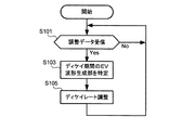
図5は、本発明の第1実施形態におけるディケイレートの調整処理を示すフローチャートである。操作部21を介して演奏者の接触による減衰の影響を反映させる機能をオンにした場合等において、調整部131によるディケイレートDRの調整処理が開始される。調整処理が開始されると、調整部131は、調整データの受信を待つ(ステップS101;No)。なお、演奏中においては、ほぼ鍵70に対する圧力の印加が存在するため、調整データは順次送信される。そのため、調整データが受信されないときは、ほとんどの場合、押鍵が行われていない。
FIG. 5 is a flowchart showing a decay rate adjustment process in the first embodiment of the present invention. When the function of reflecting the influence of attenuation due to the player's contact is turned on via the
調整部131は、調整データを受信すると(ステップS101;Yes)、ディケイ期間に属するEV波形生成部115を特定する(ステップS103)。ディケイ期間とは、ディケイタイムDTの制御下にある期間に対応する。したがって、ディケイ期間に属するEV波形生成部115とは、ディケイタイムDTにおけるエンベロープ波形を出力しているEV波形生成部115を示す。
When the
調整部131は、特定したEV波形生成部115に対して、調整データに基づいたディケイレートDRの調整を行い(ステップS105)、次の調整データの受信を待つ(ステップS101)。上記の通り、ステップS103において複数のEV波形生成部115が特定されることもあるため、ディケイレートDRの調整が、複数のEV波形生成部115に対して行われることもある。すなわち、鍵70の操作によって生成される音信号は、その操作以降における操作(他の鍵70に対する操作を含む)に応じて減衰率が調整されることになる。続いて、ディケイレートDRの調整の具体例について説明する。
The
図6は、本発明の第1実施形態におけるディケイレートの調整例を説明する図である。この例では、鍵70の押下が2回行われて、EV波形生成部115−1、115−2において順次エンベロープ波形の生成が開始されている。そして、調整部131が調整データをt1、t2のタイミングで受信した場合を示している。2回目の調整データの方が、1回目の調整データよりも調整量が少ない場合の例である。Konは、押鍵(ノートオン)があったタイミングを示している。
FIG. 6 is a diagram illustrating an example of adjusting the decay rate in the first embodiment of the present invention. In this example, the key 70 is pressed twice, and the generation of envelope waveforms is sequentially started in the EV waveform generation units 115-1 and 115-2. And the case where the
図に示すディケイレートDRは、予め決められた初期値であり、時刻t1までは、DRに応じた減衰率でエンベロープ波形が生成される。時刻t1において調整データが受信されると、調整部131は、EV波形生成部115−1、115−2のディケイレートを、調整データに応じて減衰率を増加させたディケイレートDRc1に調整する。時刻t2において調整データがさらに受信されると、調整部131は、EV波形生成部115−1、115−2のディケイレートを、調整データに応じて減衰率を減少させたディケイレートDRc2に調整する。
The decay rate DR shown in the figure is a predetermined initial value, and until time t1, an envelope waveform is generated with an attenuation rate corresponding to the DR. When adjustment data is received at time t1,
ディケイレートDRc2は、ディケイレートDRc1を基準とすると減衰率が減少しているが、ディケイレートDRを基準とすると減衰率が増加している。言い換えると、エンベロープ波形におけるディケイレートDRc2における傾きは、ディケイレートDRにおける傾きと、ディケイレートDRc1における傾きとの間になっている。したがって、鍵70への圧力の印加によって、ディケイレートが調整されると、図6に示す2つのエンベロープ波形からわかるようにディケイレートDRのまま減衰するよりも、より大きい減衰率のエンベロープ波形が得られる。これによって、演奏者に対して発音のエネルギが伝達されて、速く減衰する音を再現することができる。 Decay rate DRc2 has a reduced attenuation rate with respect to decay rate DRc1, but has an increased attenuation rate with decay rate DR as a reference. In other words, the slope at the decay rate DRc2 in the envelope waveform is between the slope at the decay rate DR and the slope at the decay rate DRc1. Therefore, when the decay rate is adjusted by applying pressure to the key 70, an envelope waveform with a larger attenuation rate is obtained than when the decay rate DR is attenuated as can be seen from the two envelope waveforms shown in FIG. It is done. As a result, the sound energy is transmitted to the performer, and a sound that decays quickly can be reproduced.
なお、調整データに基づくディケイレートの調整は、対象となる音信号の音高によらず同じ調整量であってもよいが、発音されている音高に応じて調整量が変化するようにしてもよい。この場合には、EV波形生成部115−kに対するエンベロープ波形の調整は、これに対応する波形読出部113−kに適用された制御データが示すノートナンバを調整部131が取得するようにすればよい。そして、調整部131は、ノートナンバに応じた調整量を算出すればよい。
The decay rate adjustment based on the adjustment data may be the same adjustment amount regardless of the pitch of the target sound signal, but the adjustment amount changes according to the pitch of the sound being generated. Also good. In this case, the adjustment of the envelope waveform for the EV waveform generation unit 115-k can be performed by the
一般的には低音側の発音の方が、演奏者に対してエネルギが伝達されやすい。例えば、調整量の音高依存性を持たせることで、その影響を音信号生成部111において再現できるようにしてもよい。このとき、ある鍵70の操作に応じて生成される音信号に対する減衰率よりも、さらに低い音高(低音側)のいずれかの鍵70の操作に応じて生成される音信号に対する減衰率が大きくなる調整が含まれるようにすることが望ましい。
In general, energy is more easily transmitted to the performer when the sound is generated on the bass side. For example, the effect may be reproduced by the sound
図7は、本発明の第1実施形態におけるディケイレートの調整係数の音高依存性を説明する図である。調整係数DPは、調整データにおける調整量に対して音高依存性を与えるための係数であって、例えば、調整データの値に乗算される。調整係数DPの音高依存性について、図7(a)、(b)、(c)の3つを例示する。なお、いずれの関係においても、縦軸は調整係数DPを示し、横軸は音高(ノートナンバ:1〜88)を示している。 FIG. 7 is a diagram for explaining the pitch dependency of the adjustment coefficient of the decay rate in the first embodiment of the present invention. The adjustment coefficient DP is a coefficient for giving pitch dependency to the adjustment amount in the adjustment data, and is multiplied by, for example, the value of the adjustment data. Three examples of the pitch dependence of the adjustment coefficient DP are illustrated in FIGS. 7A, 7B, and 7C. In any relationship, the vertical axis represents the adjustment coefficient DP, and the horizontal axis represents the pitch (note number: 1 to 88).
図7(a)に示す第1の例によれば、音高が高くなるほど、徐々に調整係数DPが減少していく例が開示される。この例ではノートナンバknにおいて調整係数DPが「0」となり、ノートナンバkn以上の音高では、エンベロープ波形の調整が行われない。なお、knを「89」以上に設定すれば、最高音においてもエンベロープ波形の調整が行われることになる。また、音高の増加に対する調整係数DPの減少率は、図示のとおり一定に限らず、変化してもよい。 According to the first example shown in FIG. 7A, an example is disclosed in which the adjustment coefficient DP gradually decreases as the pitch increases. In this example, the adjustment coefficient DP is “0” for the note number kn, and the envelope waveform is not adjusted for pitches of note number kn or higher. If kn is set to “89” or more, the envelope waveform is adjusted even for the highest sound. Further, the decrease rate of the adjustment coefficient DP with respect to the increase in the pitch is not limited to a constant value as illustrated, and may be changed.
図7(b)に示す第2の例によれば、ノートナンバknに対して低音側では同じ調整係数DPでエンベロープ波形の調整が行われる。一方、ノートナンバknに対して高音側ではエンベロープ波形の調整が行われない。この例においてノートナンバknが「88」である場合には、音高依存性のない調整が行われる例と同じである。 According to the second example shown in FIG. 7B, the envelope waveform is adjusted with the same adjustment coefficient DP on the bass side with respect to the note number kn. On the other hand, the envelope waveform is not adjusted on the high sound side with respect to the note number kn. In this example, when the note number kn is “88”, this is the same as the example in which the adjustment without pitch dependency is performed.
図7(c)に示す第3の例によれば、調整係数DPは、ノートナンバknにおいて最も大きく、低音側および高温側において減少している。なお、低音側と高温側とで変化率が異なっていてもよい。例えば、低音側では、調整係数DPが一定値(例えば、「1」)であってもよい。 According to the third example shown in FIG. 7C, the adjustment coefficient DP is the largest in the note number kn, and is decreased on the bass side and the high temperature side. Note that the rate of change may be different between the bass side and the high temperature side. For example, on the bass side, the adjustment coefficient DP may be a constant value (for example, “1”).
このように、第1実施形態に係る電子鍵盤楽器1は、鍵70への操作に応じてエンベロープ波形を調整することによって、アコースティック楽器の演奏者の鍵への接触による減衰の影響を含んだ発音を再現することができる。
As described above, the
<第2実施形態>
アコースティック楽器の演奏者の鍵への接触による減衰の影響を含んだ発音を再現するために、特許5664185号公報に開示される物理モデルを用いた演算処理を用いる例を、第2実施形態として説明する。
Second Embodiment
An example of using arithmetic processing using a physical model disclosed in Japanese Patent No. 5664185 in order to reproduce the sound including the influence of attenuation due to contact of the player with the key of the acoustic instrument will be described as a second embodiment. To do.
図8は、本発明の第2実施形態における音源部の機能構成を示す図である。音源部80Aは、変換部88A、物理モデル演算部100および出力部180を備える。変換部88Aは、鍵挙動測定部75から入力される情報(KC、KS、KV)およびペダル挙動測定部95から入力される情報(PC、PS)を、物理モデル演算部100において用いられる信号に変換して出力する。また、変換部88Aは、圧力測定部73から入力される情報(KC、KP)についても、物理モデル演算部100において用いられる信号に変換して出力する。物理モデル演算部100は、特許5664185号公報に開示される楽音信号合成部100に対応する。
FIG. 8 is a diagram showing a functional configuration of the sound source unit in the second embodiment of the present invention. The
物理モデル演算部100に入力される信号は、離散時間軸(t=nΔt;n=0,1,2,・・・)上で表される入力信号1〜5を含む。入力信号1(ek(nΔt))は、鍵の押込量に対応する信号であり、鍵挙動測定部75から入力される情報KC、KSに基づいて生成される。入力信号2(VH(nΔt))は、ハンマ速度に対応する信号であり、鍵挙動測定部75から入力される情報KC、KVに基づいて生成される。入力信号3(ep(nΔt))は、ダンパペダルの押込量(踏込量)に対応する信号であり、ペダル挙動測定部95から入力される情報PC、PSに基づいて生成される。入力信号4(es(nΔt))は、シフトペダルの押込量(踏込量)に対応する信号であり、ペダル挙動測定部95から入力される情報PC、PSに基づいて生成される。入力信号1〜4は、変換部88Bから出力される。入力信号1〜4は、特許5664185号公報に開示されているものと同じである。一方、入力信号5(Fv(nΔt))は、各鍵70に印加された圧力に対応する信号であり、圧力測定部73から入力され得る情報KC,KPに基づいて生成される。
Signals input to the physical
図9は、本発明の第3実施形態における変換部の処理例を示す図である。この例では、情報KCによって指定される鍵に対応する入力信号1(ek(nΔt))に、情報KSが変換される場合を示す。具体的には、ある特定のタイミングにおける情報KSが示す鍵の位置(レスト位置(rest)からエンド位置(end)の範囲)と、ekの値との関係を示している。この変換テーブルによれば、ekは、鍵がレスト位置から一定量押し込まれると、「1」から減少し始め、エンド位置に至る一定量前の段階で「0」に至るように決められている。このような変換テーブルは、入力信号1〜4に対応して設けられている。 FIG. 9 is a diagram illustrating a processing example of the conversion unit in the third embodiment of the present invention. In this example, information KS is converted into input signal 1 (e k (nΔt)) corresponding to the key specified by information KC. Specifically, the position of the key indicated by the certain information at the timing KS (ranging from a rest position (rest) end position of the (end The)), shows the relationship between the value of e k. According to this conversion table, e k is the key is pressed a predetermined amount from a rest position, starts to decrease from "1", is determined to reach the "0" in a certain amount a stage before reaching the end position Yes. Such a conversion table is provided corresponding to the input signals 1 to 4.
物理モデル演算部100は、入力信号1〜5に基づいて、グランドピアノを想定した複数のモデル(ダンパモデル、ハンマモデル、弦モデル、本体モデル、空気モデル)を含む物理モデルにより演算し、疑似ピアノ音を示す音信号を生成する。生成された音信号は、出力部180に出力され、音源部80Aの外部に出力される。物理モデル演算部100の構成について説明する。
Based on the input signals 1 to 5, the physical
図10は、本発明の第2実施形態における物理モデル演算部の機能構成を示す図である。物理モデル演算部100は、比較部101、ダンパモデル計算部102−1、102−2、ハンマモデル計算部103、弦モデル計算部104−1、104−2、本体モデル計算部105、空気モデル計算部106および化粧音生成部200を備える。ダンパモデル計算部102−1、102−2を区別しない場合には、ダンパモデル計算部102という。弦モデル計算部104−1、104−2を区別しない場合には、弦モデル計算部104という。いずれも特定の鍵において、対応する弦が2本(iw=1、2)である場合の物理モデルを想定している。弦が3本以上であれば、本体モデル計算部105に対して並列に接続される弦モデル計算部104およびダンパモデル計算部102を増やせばよい。
FIG. 10 is a diagram showing a functional configuration of the physical model calculation unit in the second embodiment of the present invention. The physical
以下に各構成についての説明をする。なお、ダンパモデル計算部102、ハンマモデル計算部103、弦モデル計算部104、本体モデル計算部105および空気モデル計算部106における物理モデル演算方法は、特許5664185号公報に開示されているものと同じである。また、物理モデル演算に用いられるパラメータを含む様々な計算上のパラメータについても特許5664185号公報に開示されているものと同じである。したがって、本明細書においては、その説明については、特許5664185号公報が参照されることによって、詳細の説明を省略する。
Each configuration will be described below. The physical model calculation method in the damper model calculation unit 102, the hammer
比較部101は、入力信号1(ek(nΔt))および入力信号3(ep(nΔt))を取得する。比較部101は、小さい方の値をeD(nΔt)として、ダンパモデル計算部102−1、102−2に出力する。
The
ダンパモデル計算部102は、ダンパについて計算する。ダンパモデル計算部102は、比較部101から出力されるeD(nΔt)および弦モデル計算部104から出力されるuk(xD,nΔt)(k=1,3)を取得する。u1(xD,nΔt)は、止音点における弦中心軸のz方向変位を示す。u3(xD,nΔt)は、止音点における弦中心軸のy方向変位を示す。ここで、z方向(k=1)は、ハンマ重心の打弦時運動方向である。x方向(k=2)とは弦の中心軸に沿った方向である。y方向(k=3)はx方向およびz方向に垂直な方向である。以下の説明においても同じである。ダンパモデル計算部102は、これらの情報を用いてfDk(nΔt)を計算して、弦モデル計算部104に出力する。fDk(nΔt)は、ダンパの抵抗力を示す。
The damper model calculation unit 102 calculates the damper. The damper model calculation unit 102 acquires e D (nΔt) output from the
ハンマモデル計算部103は、ハンマについて計算する。ハンマモデル計算部103は、比較部101から出力される入力信号2(VH(nΔt))および入力信号4(es(nΔt))を取得する。ハンマモデル計算部103は、これらの情報を用いて、fH(nΔt)を計算して、弦モデル計算部104に出力する。fH(nΔt)は、ハンマ先端が弦表面に及ぼす力を示す。
The hammer
弦モデル計算部104は、弦の振動について計算する。弦モデル計算部104は、ダンパモデル計算部102から出力されるfDk(nΔt)、ハンマモデル計算部103から出力されるfH(nΔt)および本体モデル計算部105から出力されるuBk(nΔt)(k=1,2,3)を取得する。uBk(nΔt)は、弦支持端のz方向(k=1)、x方向(k=2)、y方向(k=3)の変位を示す。弦モデル計算部104は、これらの情報を用いて、uk(xD,nΔt)(k=1,3)、u1(xH,nΔt)、fBk(nΔt)(k=1,2,3)を計算する。fBk(nΔt)は、弦が弦支持端に及ぼすz方向(k=1)、x方向(k=2)、y方向(k=3)の力を示す。u1(xH,nΔt)は、打弦点における弦中心軸のz方向変位を示す。uk(xD,nΔt)(k=1,3)は、ダンパモデル計算部102に出力される。u1(xH,nΔt)は、ハンマモデル計算部103に出力される。fBk(nΔt)(k=1,2,3)は、本体モデル計算部105に出力される。
The string model calculation unit 104 calculates the vibration of the string. The string model calculation unit 104 outputs f Dk (nΔt) output from the damper model calculation unit 102, f H (nΔt) output from the hammer
本体モデル計算部105は、本体の振動について計算する。本体モデル計算部105は、弦モデル計算部104から出力されるfBk(nΔt)(k=1,2,3)を取得する。このfBk(nΔt)(k=1,2,3)には、化粧音生成部200から出力されるFBk(nΔt)(k=1,2,3)が加算されている。FBk(nΔt)(k=1,2,3)は、化粧音により弦支持端に及ぼすz方向(k=1)、x方向(k=2)、y方向(k=3)の力を示す。本体モデル計算部105は、これらの情報を用いて、Ac(nΔt)、uBk(nΔt)(k=1,2,3)を計算する。Ac(nΔt)は、本体の固有振動モードのモード座標上での変位を示す。Ac(nΔt)は、空気モデル計算部106に出力される。uBk(nΔt)(k=1,2,3)は、弦モデル計算部104に出力される。
The main body
空気モデル計算部106は、音響放射について計算する。空気モデル計算部106は、本体モデル計算部105から出力されるAc(nΔt)を取得し、P(nΔt)を計算して出力する。P(nΔt)は、物理モデル演算部100において生成される音信号に対応する。したがって、この音信号は、出力部180に出力される。
The air
化粧音生成部200は、入力信号2(VH(nΔt))、入力信号4(es(nΔt))および入力信号5(Fv(nΔt))を取得する。また、この例では、本体モデル計算部105から出力されるAc(nΔt)についても取得される。化粧音生成部200は、これらの情報を用いてFBk(nΔt)(k=1,2,3)を計算し、fBk(nΔt)(k=1,2,3)に加算する。なお、k=2,3については、fBk(nΔt)=0として、k=1のみ加算の対象としてもよい。また、単純に加算するのではなく、減算、重み付けをした加算、積算、除算などにより合成するようにしてもよい。
Cosmetic
なお、化粧音生成部200は、入力信号2(VH(nΔt))および入力信号4(es(nΔt))に基づいて、棚板音に相当するFBk(nΔt)(k=1,2,3)が出力される点では、特許5664185号公報に開示された化粧音生成部200と同様である。一方、この例においては、FBk(nΔt)(k=1,2,3)には、本体モデル計算部105から出力されるAc(nΔt)および入力信号5(Fv(nΔt))に基づいて生成される、アコースティック楽器の演奏者の鍵への接触による減衰の影響に相当する情報も含まれる。以下、化粧音生成部200について詳細を説明する。
Incidentally, the decorative
図11は、本発明の第2実施形態における化粧音生成部の機能構成を示す図である。化粧音生成部200は、生成制御部210、波形データ読出部220、DCA(Digital Controlled Amplifier)230、DCF(Digital Controlled Filter)240、減衰演算部250および波形データ記憶部252を備える。
FIG. 11 is a diagram illustrating a functional configuration of a makeup sound generation unit according to the second embodiment of the present invention. The makeup
生成制御部210は、入力信号2(VH(nΔt))および入力信号4(es(nΔt))を取得し、これらの信号に基づいて、波形データ読出部220、DCA230およびDCF240を制御する。なお、化粧音生成部200は、これらの信号ではなく、鍵挙動測定部75およびペダル挙動測定部95から取得される情報(Fv、KC、KS、KV、PC、PS)を取得するようにしてもよい。
波形データ読出部220は、波形データ記憶部252に記憶されている波形データのうち、生成制御部210の制御により選択される波形データを読み出して出力する。波形データ記憶部252に記憶されている波形データは、棚板音に相当する波形データ(以下、棚板音波形データ)を含む。
The waveform
棚板音波形データは、グランドピアノにおいて鍵を押下したときに生じる棚板音の振動波形を示すデータである。棚板音波形データは、例えば、以下のように生成される。鍵を押下したときに弦が振動しない状態にしておき、特定の鍵を特定の速度で押下したときに生じた棚板音を、全ての鍵について弦支持端における変位として検出する。検出した変位から離散時間軸上における弦支持端に与える力FBk(nΔt)(k=1,2,3)が算出される。この情報は、上記の特定の鍵が特定の速度で押下された場合の棚板音波形データに対応する。なお、鍵の押下位置は、シフトペダルの踏み込みによって変化する。したがって、各鍵に対応する棚板音波形データについては、シフトペダルの押込量(踏込量)との組み合わせとして記憶されている。 The shelf sound waveform data is data indicating a vibration waveform of a shelf sound generated when a key is pressed on a grand piano. The shelf sound waveform data is generated as follows, for example. The string is not vibrated when the key is pressed, and the shelf sound generated when the specific key is pressed at a specific speed is detected as the displacement at the string support end for all the keys. A force F Bk (nΔt) (k = 1, 2, 3) applied to the string support end on the discrete time axis is calculated from the detected displacement. This information corresponds to the shelf sound waveform data when the specific key is pressed at a specific speed. Note that the key pressing position changes as the shift pedal is depressed. Therefore, the shelf sound waveform data corresponding to each key is stored as a combination with the depression amount (depression amount) of the shift pedal.
波形データ読出部220は、生成制御部210の制御により、入力信号2(VH(nΔt))および入力信号4(es(nΔt))に基づいて棚板音波形データSbを読み出してDCA230に出力する。
Waveform
DCA230は、生成制御部210の制御により、入力信号2(VH(nΔt))に応じた増幅率で棚板音波形データを増幅する。この例では、入力信号2(VH(nΔt))が示すハンマ速度が速いほど、この増幅率が大きくなるように制御される。
The
DCF240は、生成制御部210の制御により、入力信号2(VH(nΔt))に応じたカットオフ周波数で棚板音波形データの高周波成分を減衰させる。この例では、入力信号2(VH(nΔt))が示すハンマ速度が速いほど、このカットオフ周波数が高周波数になるように制御される。
The
減衰演算部250は、入力信号5(Fv(nΔt))および本体モデル計算部105から出力されるAc(nΔt)を取得する。減衰演算部250は、Ac(nΔt)からd/dt(Ac(nΔt))を得て、入力信号5(Fv(nΔt))に応じた係数を乗算することによって、離散時間軸上における弦支持端に与える力に相当する波形データが算出される。各鍵70に印加された圧力が大きいほど、弦支持端に与える力の大きさが大きくなるように、波形データが算出される。この波形データを弦支持端に反力として与えることによって、入力信号5(Fv(nΔt))に応じた係数に対応する減衰の効果が、本体モデル計算部105から出力されるAc(nΔt)に含まれることになる。
The
DCF240で処理された棚板音波形データと減衰演算部250において演算して得られた波形データとが合成されて、FBk(nΔt)として化粧音生成部200から出力される。このように出力される。FBk(nΔt)は、弦モデル計算部104から出力されたfBk(nΔt)に加算されることにより、弦支持端に及ぼす力には,弦の振動による力だけなく、棚板音の振動による力、および音を減衰させるための力が含まれることになる。その結果、入力信号5(Fv(nΔt))に応じた係数、すなわち、鍵70に印加された圧力に対応する減衰の効果が、本体モデル計算部105から出力されるAc(nΔt)、さらに空気モデル計算部106から出力されるP(nΔt)にも含まれる。そして、出力部180から出力される音信号にも鍵70に印加された圧力に対応する減衰の効果が含まれるものとなる。
The shelf sound waveform data processed by the
<変形例>
以上、本発明の一実施形態について説明したが、本発明は以下のように、様々な態様で実施可能である。
<Modification>
Although one embodiment of the present invention has been described above, the present invention can be implemented in various modes as follows.
(1)上記の実施形態では、電子鍵盤楽器に本発明を適用した場合の説明であったが、電子鍵盤楽器以外の電子楽器にも適用される。すなわち、鍵70以外の演奏操作子を用いた電子楽器であってもよい。例えば、演奏操作子は、ウインドシンセサイザ(管楽器型のコントローラ)のキーであってもよい。そして、圧力測定部73は、このような演奏操作子に印加される圧力を測定すればよい。
(1) In the above embodiment, the description has been given of the case where the present invention is applied to an electronic keyboard instrument, but the present invention is also applicable to an electronic musical instrument other than an electronic keyboard instrument. That is, an electronic musical instrument using performance operators other than the key 70 may be used. For example, the performance operator may be a key of a wind synthesizer (wind instrument type controller). And the
(2)第2実施形態において、特許5664185号公報に開示された物理モデル演算方法の一例に、本体部への衝撃音を生成する構成を適用する場合について説明した。特許5664185号公報に開示された物理モデル演算方法は、その他にも複数の例が開示されているが、いずれの例に対しても化粧音生成部を利用した方法により適用可能である。また、同様の思想(鍵に印加される圧力による音の減衰を再現する思想)を用いれば、その他の公知となっている物理モデル演算に対しても、鍵に印加される圧力による音の減衰を再現するための構成を適用することができる。 (2) In 2nd Embodiment, the case where the structure which produces | generates the impact sound to a main-body part was applied to an example of the physical model calculating method disclosed by the patent 5664185 gazette. A plurality of other examples of the physical model calculation method disclosed in Japanese Patent No. 5664185 have been disclosed, but any of the examples can be applied by a method using a makeup sound generation unit. In addition, if the same idea (the idea of reproducing the sound attenuation due to the pressure applied to the key) is used, the sound attenuation due to the pressure applied to the key can be applied to other known physical model calculations. It is possible to apply a configuration for reproducing.
(3)上述の実施形態において、圧力測定部73を用いない構成であってもよい。すなわち、圧力測定部73における測定結果に応じて、鍵70に印加される圧力に応じた音の減衰を再現する場合に限らない。例えば、鍵挙動測定部75における測定結果に応じて、アコースティック楽器の演奏者の鍵への接触による減衰の影響を含んだ発音を再現してもよい。
(3) In the above-mentioned embodiment, the structure which does not use the
(3−1)第1実施形態では、変換部88が、圧力測定部73から入力される情報(KC、KP)に基づいて、各鍵70における圧力値に応じた調整データを調整部131に出力していた。一方、圧力測定部73を用いない場合には、例えば、鍵挙動測定部75から入力される情報に基づいて、押下された鍵70の数に応じた調整データを調整部131に出力してもよい。この場合には、押鍵時の圧力とは関係なく、押鍵数によってエンベロープ波形の調整量が決まるように、調整データが生成されればよい。
(3-1) In the first embodiment, the
(3−2)第2実施形態に適用する場合においても同様に、化粧音生成部200(減衰演算部250)に入力される入力信号5(Fv(nΔt))を鍵挙動測定部75から入力される情報に基づいて、各鍵70に印加された圧力に対応する信号ではなく、押鍵数(押下された鍵70の数)に対応する信号とすればよい。
(3-2) Similarly, when applied to the second embodiment, the input signal 5 (Fv (nΔt)) input to the makeup sound generation unit 200 (attenuation calculation unit 250) is input from the key
(4)第2実施形態において、アコースティック楽器の演奏者の鍵への接触による減衰の影響を含んだ発音は、Ac(nΔt)に基づいて算出された力を弦支持端に反力として与えることによって再現されていたが、これ以外の演算を用いて再現されてもよい。例えば、空気モデル計算部において、入力信号5(Fv(nΔt))など各鍵70に印加された圧力または押鍵数などの情報に応じて、音信号が減衰されるような演算を施せばよい。 (4) In the second embodiment, the sound generation including the influence of the attenuation due to the contact of the player with the key of the acoustic instrument gives the force calculated based on Ac (nΔt) as a reaction force to the string support end. However, it may be reproduced using other calculations. For example, the air model calculation unit may perform an operation such that the sound signal is attenuated in accordance with information such as the input signal 5 (Fv (nΔt)) such as the pressure applied to each key 70 or the number of key presses. .
1…電子鍵盤楽器、10…制御部、21…操作部、23…表示部、30…記憶部、50…筐体、60…スピーカ、73…圧力測定部、75…鍵挙動測定部、80…音源部、88…変換部、90…ペダル装置、91…ダンパペダル、93…シフトペダル、95…ペダル挙動測定部、100…物理モデル演算部、101…比較部、102…ダンパモデル計算部、103…ハンマモデル計算部、104…弦モデル計算部、105…本体モデル計算部、106…空気モデル計算部、111…音信号生成部、113…波形読出部、115…EV波形生成部、117…乗算器、119…波形合成部、131…調整部、151…波形データ記憶部、180…出力部、200…化粧音生成部、210…生成制御部、220…波形データ読出部、230…DCA、240…DCF、250…減衰演算部、252…波形データ記憶部
DESCRIPTION OF
Claims (8)
前記演奏操作子への操作による当該演奏操作子の挙動を測定し、当該挙動に対応した第1測定データを出力する第1測定部と、
前記第1測定データに基づいて前記操作に対応した音信号を生成し、当該操作以降における前記演奏操作子のいずれかへの操作に応じて当該音信号の減衰率を調整する音源部と、
を備えることを特徴とする電子楽器。 Multiple performance controls,
A first measuring unit that measures the behavior of the performance operator by operating the performance operator and outputs first measurement data corresponding to the behavior;
A sound source unit that generates a sound signal corresponding to the operation based on the first measurement data, and adjusts the attenuation rate of the sound signal according to an operation to any of the performance operators after the operation;
An electronic musical instrument characterized by comprising:
前記音源部は、前記第2測定データに基づいて前記減衰率を調整することを特徴とする請求項1乃至請求項4のいずれかに記載の電子楽器。 A second measuring unit that measures a pressure applied to the performance operator by operating the performance operator and outputs second measurement data corresponding to the pressure;
5. The electronic musical instrument according to claim 1, wherein the sound source unit adjusts the attenuation rate based on the second measurement data.
前記音源部は、前記第1測定データに基づいて、アコースティックピアノの少なくとも弦の振動および当該弦と接続される本体部の振動を、物理モデルを用いて演算し、演算結果に基づいて前記減衰率が調整された音信号を生成し、
前記物理モデルの演算には、前記本体部の振動を利用して前記減衰率を調整する演算を含むことを特徴とする請求項1に記載の電子楽器。 The performance operator is a key,
The sound source unit calculates a vibration of at least a string of the acoustic piano and a vibration of the main body connected to the string based on the first measurement data using a physical model, and the attenuation rate based on a calculation result Produces a tuned sound signal,
The electronic musical instrument according to claim 1, wherein the calculation of the physical model includes a calculation of adjusting the attenuation rate using vibration of the main body.
前記物理モデルの演算には、前記第2測定データに基づいて前記減衰率を調整する演算を含むことを特徴とする請求項7に記載の電子楽器。 A second measuring unit that measures a pressure applied to the performance operator by operating the performance operator and outputs second measurement data corresponding to the pressure;
The electronic musical instrument according to claim 7, wherein the calculation of the physical model includes a calculation for adjusting the attenuation rate based on the second measurement data.
Priority Applications (1)
| Application Number | Priority Date | Filing Date | Title |
|---|---|---|---|
| JP2016079448A JP6717017B2 (en) | 2016-04-12 | 2016-04-12 | Electronic musical instrument, sound signal generation method and program |
Applications Claiming Priority (1)
| Application Number | Priority Date | Filing Date | Title |
|---|---|---|---|
| JP2016079448A JP6717017B2 (en) | 2016-04-12 | 2016-04-12 | Electronic musical instrument, sound signal generation method and program |
Publications (2)
| Publication Number | Publication Date |
|---|---|
| JP2017191165A true JP2017191165A (en) | 2017-10-19 |
| JP6717017B2 JP6717017B2 (en) | 2020-07-01 |
Family
ID=60085153
Family Applications (1)
| Application Number | Title | Priority Date | Filing Date |
|---|---|---|---|
| JP2016079448A Active JP6717017B2 (en) | 2016-04-12 | 2016-04-12 | Electronic musical instrument, sound signal generation method and program |
Country Status (1)
| Country | Link |
|---|---|
| JP (1) | JP6717017B2 (en) |
Cited By (2)
| Publication number | Priority date | Publication date | Assignee | Title |
|---|---|---|---|---|
| WO2019092776A1 (en) * | 2017-11-07 | 2019-05-16 | ヤマハ株式会社 | Sound output device |
| JPWO2020054070A1 (en) * | 2018-09-14 | 2021-08-30 | ヤマハ株式会社 | Sound signal generators, keyboard instruments and programs |
-
2016
- 2016-04-12 JP JP2016079448A patent/JP6717017B2/en active Active
Cited By (7)
| Publication number | Priority date | Publication date | Assignee | Title |
|---|---|---|---|---|
| WO2019092776A1 (en) * | 2017-11-07 | 2019-05-16 | ヤマハ株式会社 | Sound output device |
| CN111295705A (en) * | 2017-11-07 | 2020-06-16 | 雅马哈株式会社 | Sound output device |
| JPWO2019092776A1 (en) * | 2017-11-07 | 2020-10-22 | ヤマハ株式会社 | Sound output device |
| US11138961B2 (en) * | 2017-11-07 | 2021-10-05 | Yamaha Corporation | Sound output device and non-transitory computer-readable storage medium |
| CN111295705B (en) * | 2017-11-07 | 2024-04-09 | 雅马哈株式会社 | Sound output device and recording medium |
| JPWO2020054070A1 (en) * | 2018-09-14 | 2021-08-30 | ヤマハ株式会社 | Sound signal generators, keyboard instruments and programs |
| JP7306402B2 (en) | 2018-09-14 | 2023-07-11 | ヤマハ株式会社 | SOUND SIGNAL GENERATOR, KEYBOARD INSTRUMENT AND PROGRAM |
Also Published As
| Publication number | Publication date |
|---|---|
| JP6717017B2 (en) | 2020-07-01 |
Similar Documents
| Publication | Publication Date | Title |
|---|---|---|
| CN107863094B (en) | Electronic wind instrument, musical sound generation device, musical sound generation method | |
| US11961499B2 (en) | Sound signal generation device, keyboard instrument and sound signal generation method | |
| US11222618B2 (en) | Sound signal generation device, keyboard instrument, and sound signal generation method | |
| US10762879B2 (en) | Piano system and method thereof | |
| US11138961B2 (en) | Sound output device and non-transitory computer-readable storage medium | |
| US20160111083A1 (en) | Phoneme information synthesis device, voice synthesis device, and phoneme information synthesis method | |
| US20100107857A1 (en) | Tone Control Apparatus and Method | |
| US11694665B2 (en) | Sound source, keyboard musical instrument, and method for generating sound signal | |
| US11551653B2 (en) | Electronic musical instrument | |
| JP6717017B2 (en) | Electronic musical instrument, sound signal generation method and program | |
| JP2007188030A (en) | Keyboard apparatus of electronic musical instrument | |
| JP7024864B2 (en) | Signal processing equipment, programs and sound sources | |
| JP6736930B2 (en) | Electronic musical instrument and sound signal generation method | |
| EP3757984B1 (en) | Electronic musical instrument, method and program | |
| US20230068966A1 (en) | Signal generation device, signal generation method and non-transitory computer-readable storage medium | |
| JP5827484B2 (en) | Music control device | |
| JP2020064189A (en) | Electronic keyboard instrument, method and program | |
| JP2004294833A (en) | Electronic piano |
Legal Events
| Date | Code | Title | Description |
|---|---|---|---|
| A621 | Written request for application examination |
Free format text: JAPANESE INTERMEDIATE CODE: A621 Effective date: 20190221 |
|
| A977 | Report on retrieval |
Free format text: JAPANESE INTERMEDIATE CODE: A971007 Effective date: 20200128 |
|
| A131 | Notification of reasons for refusal |
Free format text: JAPANESE INTERMEDIATE CODE: A131 Effective date: 20200303 |
|
| A521 | Written amendment |
Free format text: JAPANESE INTERMEDIATE CODE: A523 Effective date: 20200312 |
|
| TRDD | Decision of grant or rejection written | ||
| A01 | Written decision to grant a patent or to grant a registration (utility model) |
Free format text: JAPANESE INTERMEDIATE CODE: A01 Effective date: 20200512 |
|
| A61 | First payment of annual fees (during grant procedure) |
Free format text: JAPANESE INTERMEDIATE CODE: A61 Effective date: 20200525 |
|
| R151 | Written notification of patent or utility model registration |
Ref document number: 6717017 Country of ref document: JP Free format text: JAPANESE INTERMEDIATE CODE: R151 |