JP2017190968A - Gas sensor water testing method - Google Patents
Gas sensor water testing method Download PDFInfo
- Publication number
- JP2017190968A JP2017190968A JP2016079327A JP2016079327A JP2017190968A JP 2017190968 A JP2017190968 A JP 2017190968A JP 2016079327 A JP2016079327 A JP 2016079327A JP 2016079327 A JP2016079327 A JP 2016079327A JP 2017190968 A JP2017190968 A JP 2017190968A
- Authority
- JP
- Japan
- Prior art keywords
- water
- exhaust pipe
- gas sensor
- engine
- moisture
- Prior art date
- Legal status (The legal status is an assumption and is not a legal conclusion. Google has not performed a legal analysis and makes no representation as to the accuracy of the status listed.)
- Granted
Links
Images


Landscapes
- Measuring Oxygen Concentration In Cells (AREA)
Abstract
【課題】短時間で水分を排気管内に分散して付着させエンジンを駆動させることでガスセンサに水分を付着させる被水試験の方法を提供する。【解決手段】ガスセンサの被水試験方法は、エンジンが停止した状態で排気管120に水噴霧装置300で水滴WS又は水蒸気発生装置400で水蒸気を注入することによって、排気管内に水分を貯める注水工程と、注水工程の後に、エンジンを駆動させることによって、排気管に排気ガスを流通させて排気管内の水分を飛散させてガスセンサに水分を付着させる被水工程と、を備える。【選択図】図3The present invention provides a wet test method for attaching moisture to a gas sensor by dispersing and attaching moisture in an exhaust pipe in a short time and driving an engine. A water sensor testing method includes a water injection process in which water is stored in an exhaust pipe by injecting water into the exhaust pipe 120 with water droplets WS or water vapor with a water vapor generator 400 while the engine is stopped. And after the water injection process, the engine is driven to circulate the exhaust gas through the exhaust pipe to disperse the water in the exhaust pipe and attach the moisture to the gas sensor. [Selection] Figure 3
Description
この発明は、ガスセンサの被水試験方法に関する。 The present invention relates to a method for testing the wetness of a gas sensor.
従来から、内燃機関の排気ガスのうちの特定のガス成分の濃度測定を行うために、ガスセンサが利用されている。特許文献1,2には、ガスセンサの被水による影響を調べるために被水試験を行う方法が開示されている。 Conventionally, a gas sensor has been used to measure the concentration of a specific gas component in the exhaust gas of an internal combustion engine. Patent Documents 1 and 2 disclose a method of performing a water test in order to examine the influence of water on the gas sensor.
ガスセンサの被水試験では、排気管内に水を貯めるための前工程を行った後に、エンジンをレーシング(空ぶかし)することにより排気管内の水分を飛散させてガスセンサに水分を付着させる被水工程を実行する。しかしながら、従来技術では、前工程にかなりの長時間を要するという問題があった。例えば、特許文献2の方法では、前工程として、排気管を氷点下まで冷却した後にエンジンを始動してアイドル運転する、というサイクルを複数回実行していたので、前工程に数時間を要していた。 In the moisture test of the gas sensor, after performing the pre-process for storing water in the exhaust pipe, the water is applied to the gas sensor by scattering the moisture in the exhaust pipe by racing the engine. Execute the process. However, the conventional technique has a problem that it takes a considerably long time for the previous process. For example, in the method of Patent Document 2, since the cycle of starting the engine and performing idle operation after cooling the exhaust pipe to below the freezing point is executed a plurality of times as the previous step, several hours are required for the previous step. It was.
本発明は、上述の課題を解決するためになされたものであり、以下の形態として実現することが可能である。 The present invention has been made to solve the above-described problems, and can be realized as the following forms.
(1)本発明の一形態によれば、エンジンと、前記エンジンの排気ガスを流通させる排気管と、前記排気管に取り付けられたガスセンサと、を有する試験装置を用いて前記ガスセンサの被水試験を行う方法が提供される。この試験方法は、前記エンジンが停止した状態で前記排気管に霧状の水又は水蒸気を注入することによって、前記排気管の内壁面に水分を付着させる注水工程と;前記注水工程の後に、前記エンジンを駆動させることによって、前記排気管に排気ガスを流通させて前記排気管内の水分を飛散させて前記ガスセンサに水分を付着させる被水工程と;を備えることを特徴とする。
このガスセンサの被水試験方法によれば、被水工程の前工程である注水工程において、エンジンが停止した状態で排気管に霧状の水又は水蒸気を注入することによって排気管の内壁面に水分を付着させるので、従来技術に比べて短時間で排気管内に水分を分散して付着させることができる。
(1) According to one aspect of the present invention, the water sensor test of the gas sensor is performed using a test apparatus that includes an engine, an exhaust pipe through which the exhaust gas of the engine circulates, and a gas sensor attached to the exhaust pipe. A method of performing is provided. The test method includes a water injection step of injecting water into the exhaust pipe by injecting mist-like water or water vapor into the exhaust pipe with the engine stopped; and after the water injection step, And a wet process for causing the exhaust gas to flow through the exhaust pipe to cause the moisture in the exhaust pipe to scatter and to attach the moisture to the gas sensor by driving the engine.
According to the water test method of this gas sensor, in the water injection process, which is the previous process of the water process, water is injected into the inner wall surface of the exhaust pipe by injecting mist-like water or water vapor into the exhaust pipe while the engine is stopped. Therefore, moisture can be dispersed and deposited in the exhaust pipe in a shorter time than in the prior art.
(2)上記ガスセンサの被水試験方法において、前記注水工程において、圧縮空気によって霧状の水を発生させるノズルを有する水噴霧装置を用いて前記排気管に前記霧状の水を注入するものとしてもよい。
この構成によれば、水噴霧装置を用いて排気管に霧状の水を短時間で注入できる。
(2) In the water test method for the gas sensor, in the water injection step, the water spray device having a nozzle for generating water spray by compressed air is used to inject the water spray into the exhaust pipe. Also good.
According to this configuration, mist-like water can be injected into the exhaust pipe in a short time using the water spray device.
(3)上記ガスセンサの被水試験方法において、前記注水工程において、熱源によって水蒸気を発生させる水蒸気発生装置を用いて前記排気管に前記水蒸気を注入するものとしてもよい。
この構成によれば、水蒸気発生装置を用いて排気管に水蒸気を短時間で注入できる。
(3) In the water test method for the gas sensor, in the water injection step, the water vapor may be injected into the exhaust pipe using a water vapor generator that generates water vapor by a heat source.
According to this configuration, it is possible to inject water vapor into the exhaust pipe in a short time using the water vapor generator.
なお、本発明は、種々の形態で実現することが可能であり、例えば、ガスセンサの試験方法や試験装置等の形態で実現することができる。 The present invention can be realized in various forms, for example, in the form of a gas sensor test method, a test apparatus, or the like.
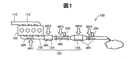
図1は、ガスセンサの被水試験を行う試験装置100の構成を示す説明図である。この試験装置100は、実際の自動車を用いた試験装置であり、内燃機関であるエンジン150と、吸気管110と、排気管120とを有する。なお、試験装置としては、エンジン、吸気管、排気管等を有するエンジンベンチシステムを用いても良い。吸気管110は吸気マニホールド112を有し、排気管120は排気マニホールド122を有する。排気管120には、更に、ターボチャージャ124と、触媒コンバータ126と、複数のガスセンサ200とが設けられている。排気管120には、水分を排気管120内に注入するために複数の注入位置WP1〜WP5が設けられている。これらの注入位置WP1〜WP5からの水分の注入方法については後述する。なお、水分の注入位置を複数設ける必要は無く、1つ以上設けておけば良い。複数のガスセンサ200としては、通常は異なる種類のガスセンサ(例えばA/Fセンサと酸素センサ)が排気管120に設置されるが、ここでは説明の便宜上、同じ符号を付している。また、ターボチャージャ124や触媒コンバータ126などの付属装置は、省略してもよい。
FIG. 1 is an explanatory diagram illustrating a configuration of a
図2は、試験装置100を用いたガスセンサ200の被水試験のフローチャートである。工程S210では、エンジン150が停止した状態で、排気管120内に結露水が発生しやすい低温(例えば−10℃)まで試験装置100を冷却する。この冷却工程S210を実行するために、試験装置100を試験室内に収容し、その試験室全体を冷房装置で冷却することが好ましい。但し、この冷却工程S210は省略し、次の注水工程S220を常温で実施してもよい。
FIG. 2 is a flowchart of a water test of the
次の工程S220では、エンジン150が停止した状態で、注入位置WP1〜WP5のうちの1つ以上の注入位置から、注水装置を用いて排気管120内に注水を行う。なお、冷却工程S210と注水工程S220は、次の被水工程S230の前段階として行われるので、2つの工程S210,S220を併せて「前工程」と呼ぶことが可能である。
In the next step S220, water is injected into the
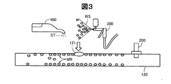
図3は、実施形態における注水工程S220の様子を示す概念図である。ここでは、排気管120に設けられた注水孔121に、水噴霧装置300又は水蒸気発生装置400を用いて水分WRが注入される。水噴霧装置300としては、例えば、圧縮空気を用いて霧状の水滴WSを発生させる2流体ノズルを有する装置や、超音波振動子を用いて霧状の水滴WSを発生させる装置などを利用することができる。また、水蒸気発生装置400としては、ヒーターなどの熱源によって水蒸気STを発生させる装置を利用することができる。水噴霧装置300を用いる場合には、ノズルの先端形状や圧縮空気の圧力などの噴霧条件を変更することによって、排気管120への注水量や注水範囲を変更できる。また、水蒸気発生装置400を用いる場合には、ノズルの先端形状やヒータ出力などの水蒸気発生条件を変更することによって、排気管120への注水量や注水範囲を変更できる。
FIG. 3 is a conceptual diagram showing a state of the water injection step S220 in the embodiment. Here, water WR is injected into the
この注水工程S220により、排気管120の内壁面に水分WRを分散して付着させることが可能である。また、前述した冷却工程S210において試験装置100を0℃以下に冷却していた場合には、水分WRの一部は氷として排気管120の内壁面に付着する。この注水工程の後、注水孔121はメクラ栓等を用いて封止される。なお、注水孔121を排気管120に設ける代わりに、ガスセンサ200が取り付けられるポートを用いて注水を行うようにしてもよい。
By this water injection step S220, it is possible to disperse and attach the moisture WR to the inner wall surface of the
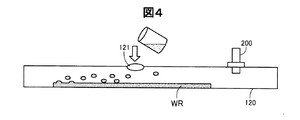
図4は、比較例における注水工程の様子を示す概念図である。ここでは、排気管120に設けられた注水孔121に、液体状の水(液水)が注入されている。この場合には、水分WRは液水の形態で排気管120内の底部に溜まる状態となる。
FIG. 4 is a conceptual diagram showing a state of the water injection process in the comparative example. Here, liquid water (liquid water) is injected into a
図3に示したように、実施形態における注水工程S220では、霧状の水滴WS又は水蒸気STの形態で水分WRを排気管120に注入するので、液水の形態で水分WRを注入した場合に比べて、排気管120内に広く分散した状態で水分WRを排気管120の内壁面に付着させることができる。従って、従来技術のように、排気管を氷点下まで冷却した後にエンジンを始動してアイドル運転する、というサイクルを複数回実行する必要が無く、従来に比べて短時間で水分WRを排気管120内に分散して付着させることが可能である。
As shown in FIG. 3, in the water injection step S220 in the embodiment, since the water WR is injected into the
なお、注水工程S220では、ガスセンサ200に水分WRが付着しないことが好ましい。この理由は、次の被水工程S230においてエンジンをレーシングしたときにガスセンサ200に水分WRがどの程度付着するかを調べたいので、被水工程S230の前にはガスセンサ200に水分WRを付着させたくないからである。この意味では、注水工程S220では、ガスセンサ200を排気管120から取り外した状態で実行することが好ましい。この場合には、注水の完了後にガスセンサ200が排気管120に取り付けられる。但し、注水孔121がガスセンサ200から十分に遠く離れた位置に設けられている場合には、ガスセンサ200を排気管120に装着した状態で注水工程S220を実行してもよい。
In addition, it is preferable that the water | moisture content WR does not adhere to the
こうして前工程S210,S220が終了すると、被水工程S230(図2)が実行される。被水工程S230では、エンジン150を駆動させることによって、排気管120に排気ガスを流通させて排気管120内の水分WRを飛散させ、ガスセンサ200に水分WRを付着させる。そして、ガスセンサ200の素子部分(図示省略)が水分WRの飛散による熱衝撃で割れるリスクを確認する。この確認を行う方法としては、例えば、ガスセンサ200の素子部分を水変色性の着色剤で着色しておく方法を採用できる。こうすれば、ガスセンサ200の素子部分に水分WRが付着したことによる色の変化の有無を目視で調べることができ、その変色の程度から、ガスセンサ200が熱衝撃で割れるリスクを確認することが可能となる。なお、被水工程S230では、水分WRを十分に飛散させるために、エンジン150のレーシングとアイドリングのセットを複数回繰り返し実行することが好ましい。
When the previous steps S210 and S220 are completed in this way, a wet process S230 (FIG. 2) is executed. In the wet process S230, by driving the
図5(A)は、実施形態の被水試験のタイミングチャートであり、図5(B)は、比較例の被水試験のタイミングチャートである。これらの図において、横軸は時間を示し、縦軸はエンジン150の回転数を示している。
FIG. 5A is a timing chart of the wet test of the embodiment, and FIG. 5B is a timing chart of the wet test of the comparative example. In these drawings, the horizontal axis indicates time, and the vertical axis indicates the rotational speed of the
図5(A)に示す実施形態では、まず、図2で説明した前工程(冷却工程S210と注水工程S220)により排気管120内に水分を注入する。このとき、前工程のうちの注水工程S220(図3)では、霧状の水滴WS又は水蒸気STの形態で水分WRを排気管120に注入するので、短時間で水分WRを排気管120内に分散して付着させることが可能である。その後、被水工程S230において、エンジン150を駆動させることによってガスセンサ200に水分を付着させる。なお、この例では、エンジン150の駆動の態様として,レーシング(空ぶかし)を利用している。また、被水工程S230において、エンジン150のレーシングとアイドリングのセットを4回繰り返し実行している。
In the embodiment shown in FIG. 5A, first, moisture is injected into the
一方、図5(B)に示す比較例では、前工程において、排気管120を氷点下まで冷却した後にエンジン150を始動してアイドル運転する、というサイクルを4回実行している。このため、前工程として極めて長い時間(例えば約4時間)を要する。
On the other hand, in the comparative example shown in FIG. 5B, in the previous step, the
このように、実施形態の試験方法では、前工程のうちの注水工程S220において霧状の水滴WS又は水蒸気STの形態で水分WRを排気管120に注入するので、比較例に比べて短時間で水分WRを排気管120の内壁面に分散して付着させることが可能である。この結果、全体の試験時間を短縮することができ、試験効率が向上する。また、水噴霧装置300や水蒸気発生装置400を使用して排気管120内へ注水を行うので、排気管120の内壁面に水分を均等に付着させることが可能であり、短時間で従来技術と同等の排気管内環境を再現できる。更に、水噴霧装置300や水蒸気発生装置400を用いて注水を行えば、注水量が明確になるため、車両やエンジンごとの被水環境について比較が容易となる。
As described above, in the test method of the embodiment, the water WR is injected into the
・変形例
なお、この発明は上記の実施例や実施形態に限られるものではなく、その要旨を逸脱しない範囲において種々の態様において実施することが可能である。
Modifications Note that the present invention is not limited to the above examples and embodiments, and can be implemented in various modes without departing from the scope of the invention.
・変形例1:
上述した実施形態の試験装置の構成は例示であり、本発明はこれ以外の種々の構成を有する試験装置を利用した試験方法にも適用可能である。また、被水工程S230におけるエンジン150の駆動の態様としては、図5(A)に示したレーシング以外の他の態様を利用しても良い。例えば、エンジン150の始動のみを利用して被水工程S230を実行しても良い。この場合には、例えば、エンジン150を始動させて直ぐに停止する、という動作を複数回以上繰り返して行うことが好ましい。
・ Modification 1:
The configuration of the test apparatus of the above-described embodiment is an exemplification, and the present invention can be applied to a test method using a test apparatus having various configurations other than this. Moreover, you may utilize aspects other than the racing shown to FIG. 5 (A) as a drive aspect of the
100…試験装置
110…吸気管
112…吸気マニホールド
120…排気管
121…注水孔
122…排気マニホールド
124…ターボチャージャ
126…触媒コンバータ
150…エンジン
200…ガスセンサ
300…水噴霧装置
400…水蒸気発生装置
DESCRIPTION OF
Claims (3)
前記エンジンが停止した状態で前記排気管に霧状の水又は水蒸気を注入することによって、前記排気管の内壁面に水分を付着させる注水工程と、
前記注水工程の後に、前記エンジンを駆動させることによって、前記排気管に排気ガスを流通させて前記排気管内の水分を飛散させて前記ガスセンサに水分を付着させる被水工程と、
を備えることを特徴とするガスセンサの被水試験方法。 A method for performing a water test of the gas sensor using a test apparatus having an engine, an exhaust pipe for circulating the exhaust gas of the engine, and a gas sensor attached to the exhaust pipe,
A water injection step for injecting water into the inner wall surface of the exhaust pipe by injecting mist-like water or water vapor into the exhaust pipe with the engine stopped;
Subsequent to the water injection step, by driving the engine, the exhaust gas is allowed to flow through the exhaust pipe and the moisture in the exhaust pipe is scattered to attach the moisture to the gas sensor;
A wet test method for a gas sensor, comprising:
前記注水工程において、圧縮空気によって霧状の水を発生させるノズルを有する水噴霧装置を用いて前記排気管に前記霧状の水を注入することを特徴とするガスセンサの被水試験方法。 A method for testing a moisture of a gas sensor according to claim 1,
A water sensor testing method for a gas sensor, wherein, in the water injection step, the mist water is injected into the exhaust pipe using a water spray device having a nozzle that generates mist water by compressed air.
前記注水工程において、熱源によって水蒸気を発生させる水蒸気発生装置を用いて前記排気管に前記水蒸気を注入することを特徴とするガスセンサの被水試験方法。 A method for testing a moisture of a gas sensor according to claim 1,
In the water injection step, a water sensor test method for a gas sensor, wherein the water vapor is injected into the exhaust pipe using a water vapor generator that generates water vapor with a heat source.
Priority Applications (1)
| Application Number | Priority Date | Filing Date | Title |
|---|---|---|---|
| JP2016079327A JP6568499B2 (en) | 2016-04-12 | 2016-04-12 | Test method for water exposure of gas sensor |
Applications Claiming Priority (1)
| Application Number | Priority Date | Filing Date | Title |
|---|---|---|---|
| JP2016079327A JP6568499B2 (en) | 2016-04-12 | 2016-04-12 | Test method for water exposure of gas sensor |
Publications (2)
| Publication Number | Publication Date |
|---|---|
| JP2017190968A true JP2017190968A (en) | 2017-10-19 |
| JP6568499B2 JP6568499B2 (en) | 2019-08-28 |
Family
ID=60085949
Family Applications (1)
| Application Number | Title | Priority Date | Filing Date |
|---|---|---|---|
| JP2016079327A Active JP6568499B2 (en) | 2016-04-12 | 2016-04-12 | Test method for water exposure of gas sensor |
Country Status (1)
| Country | Link |
|---|---|
| JP (1) | JP6568499B2 (en) |
Cited By (1)
| Publication number | Priority date | Publication date | Assignee | Title |
|---|---|---|---|---|
| CN110274990A (en) * | 2018-03-13 | 2019-09-24 | 日本碍子株式会社 | The water spray suppression test device and method of gas sensor |
-
2016
- 2016-04-12 JP JP2016079327A patent/JP6568499B2/en active Active
Cited By (2)
| Publication number | Priority date | Publication date | Assignee | Title |
|---|---|---|---|---|
| CN110274990A (en) * | 2018-03-13 | 2019-09-24 | 日本碍子株式会社 | The water spray suppression test device and method of gas sensor |
| US11061007B2 (en) | 2018-03-13 | 2021-07-13 | Ngk Insulators, Ltd. | Wetting test apparatus and method for gas sensor |
Also Published As
| Publication number | Publication date |
|---|---|
| JP6568499B2 (en) | 2019-08-28 |
Similar Documents
| Publication | Publication Date | Title |
|---|---|---|
| US9512764B2 (en) | Ammonia storage management for SCR catalyst | |
| US10352223B2 (en) | Method for cold start emissions diagnostic | |
| US8776500B2 (en) | System and method for hydrocarbon adsorber regeneration in a hybrid vehicle | |
| US20150308321A1 (en) | Exhaust emission prediction system and method | |
| RU2016133698A (en) | METHOD FOR REDUCING NOx EMISSIONS FROM ENGINE | |
| JP2010019178A (en) | Engine control device | |
| SE535958C2 (en) | Method and control device for starting an internal combustion engine including a heating device for heating a coolant | |
| JP2013534291A (en) | Operation method of exhaust gas treatment device | |
| JP6568499B2 (en) | Test method for water exposure of gas sensor | |
| US10358972B2 (en) | Method for spraying a fluid onto a charge air cooler of a motor vehicle | |
| JP5794386B2 (en) | Control unit for gasoline engine | |
| US10066576B2 (en) | Dual injection during intake stroke for improved catalyst light off | |
| US10385773B2 (en) | Method of removing carbons from vehicle engine | |
| US8883101B2 (en) | Method for operating an exhaust gas system for an internal combustion engine | |
| US10138794B2 (en) | Methods of cleaning gas sensors | |
| CN107725156B (en) | Method for controlling detection and cleaning of diesel exhaust fluid injector deposits | |
| KR100534705B1 (en) | System for estimating engine exhaust gas temperature | |
| CN102235213B (en) | For the method for operation of combustion engine | |
| US7146798B2 (en) | Method for control of a diagnosis of a catalyst in the exhaust of an internal combustion engine | |
| IT201800020851A1 (en) | METHOD AND DEVICE FOR CONTROL OF AT LEAST ONE SCR CATALYTIC CONVERTER OF A VEHICLE | |
| JP6217662B2 (en) | Additive supply device | |
| CN102330600A (en) | Engine heater use detection systems and methods | |
| RU2019131105A (en) | Improvement of the installation for cleaning an internal combustion engine | |
| CN206267943U (en) | A kind of generator water tank motor control assembly and cooling system | |
| JP2016079957A (en) | Control device for vehicle |
Legal Events
| Date | Code | Title | Description |
|---|---|---|---|
| A621 | Written request for application examination |
Free format text: JAPANESE INTERMEDIATE CODE: A621 Effective date: 20180927 |
|
| A977 | Report on retrieval |
Free format text: JAPANESE INTERMEDIATE CODE: A971007 Effective date: 20190613 |
|
| TRDD | Decision of grant or rejection written | ||
| A01 | Written decision to grant a patent or to grant a registration (utility model) |
Free format text: JAPANESE INTERMEDIATE CODE: A01 Effective date: 20190716 |
|
| A61 | First payment of annual fees (during grant procedure) |
Free format text: JAPANESE INTERMEDIATE CODE: A61 Effective date: 20190802 |
|
| R150 | Certificate of patent or registration of utility model |
Ref document number: 6568499 Country of ref document: JP Free format text: JAPANESE INTERMEDIATE CODE: R150 |
|
| R250 | Receipt of annual fees |
Free format text: JAPANESE INTERMEDIATE CODE: R250 |
|
| S531 | Written request for registration of change of domicile |
Free format text: JAPANESE INTERMEDIATE CODE: R313531 |
|
| R350 | Written notification of registration of transfer |
Free format text: JAPANESE INTERMEDIATE CODE: R350 |
|
| R250 | Receipt of annual fees |
Free format text: JAPANESE INTERMEDIATE CODE: R250 |
|
| R250 | Receipt of annual fees |
Free format text: JAPANESE INTERMEDIATE CODE: R250 |
|
| R250 | Receipt of annual fees |
Free format text: JAPANESE INTERMEDIATE CODE: R250 |