JP2017190894A - Soot blower - Google Patents
Soot blower Download PDFInfo
- Publication number
- JP2017190894A JP2017190894A JP2016079616A JP2016079616A JP2017190894A JP 2017190894 A JP2017190894 A JP 2017190894A JP 2016079616 A JP2016079616 A JP 2016079616A JP 2016079616 A JP2016079616 A JP 2016079616A JP 2017190894 A JP2017190894 A JP 2017190894A
- Authority
- JP
- Japan
- Prior art keywords
- casing
- injection pipe
- pressure vessel
- injection
- support portion
- Prior art date
- Legal status (The legal status is an assumption and is not a legal conclusion. Google has not performed a legal analysis and makes no representation as to the accuracy of the status listed.)
- Granted
Links
Images

Classifications
-
- F—MECHANICAL ENGINEERING; LIGHTING; HEATING; WEAPONS; BLASTING
- F23—COMBUSTION APPARATUS; COMBUSTION PROCESSES
- F23J—REMOVAL OR TREATMENT OF COMBUSTION PRODUCTS OR COMBUSTION RESIDUES; FLUES
- F23J3/00—Removing solid residues from passages or chambers beyond the fire, e.g. from flues by soot blowers
- F23J3/02—Cleaning furnace tubes; Cleaning flues or chimneys
-
- F—MECHANICAL ENGINEERING; LIGHTING; HEATING; WEAPONS; BLASTING
- F23—COMBUSTION APPARATUS; COMBUSTION PROCESSES
- F23J—REMOVAL OR TREATMENT OF COMBUSTION PRODUCTS OR COMBUSTION RESIDUES; FLUES
- F23J3/00—Removing solid residues from passages or chambers beyond the fire, e.g. from flues by soot blowers
- F23J3/02—Cleaning furnace tubes; Cleaning flues or chimneys
- F23J3/023—Cleaning furnace tubes; Cleaning flues or chimneys cleaning the fireside of watertubes in boilers
-
- F—MECHANICAL ENGINEERING; LIGHTING; HEATING; WEAPONS; BLASTING
- F28—HEAT EXCHANGE IN GENERAL
- F28G—CLEANING OF INTERNAL OR EXTERNAL SURFACES OF HEAT-EXCHANGE OR HEAT-TRANSFER CONDUITS, e.g. WATER TUBES OR BOILERS
- F28G1/00—Non-rotary, e.g. reciprocated, appliances
- F28G1/16—Non-rotary, e.g. reciprocated, appliances using jets of fluid for removing debris
-
- F—MECHANICAL ENGINEERING; LIGHTING; HEATING; WEAPONS; BLASTING
- F28—HEAT EXCHANGE IN GENERAL
- F28G—CLEANING OF INTERNAL OR EXTERNAL SURFACES OF HEAT-EXCHANGE OR HEAT-TRANSFER CONDUITS, e.g. WATER TUBES OR BOILERS
- F28G15/00—Details
- F28G15/003—Control arrangements
-
- F—MECHANICAL ENGINEERING; LIGHTING; HEATING; WEAPONS; BLASTING
- F28—HEAT EXCHANGE IN GENERAL
- F28G—CLEANING OF INTERNAL OR EXTERNAL SURFACES OF HEAT-EXCHANGE OR HEAT-TRANSFER CONDUITS, e.g. WATER TUBES OR BOILERS
- F28G15/00—Details
- F28G15/02—Supports for cleaning appliances, e.g. frames
-
- F—MECHANICAL ENGINEERING; LIGHTING; HEATING; WEAPONS; BLASTING
- F23—COMBUSTION APPARATUS; COMBUSTION PROCESSES
- F23D—BURNERS
- F23D2900/00—Special features of, or arrangements for burners using fluid fuels or solid fuels suspended in a carrier gas
- F23D2900/21—Burners specially adapted for a particular use
- F23D2900/21007—Burners specially adapted for a particular use for producing soot, e.g. nanoparticle soot
-
- F—MECHANICAL ENGINEERING; LIGHTING; HEATING; WEAPONS; BLASTING
- F23—COMBUSTION APPARATUS; COMBUSTION PROCESSES
- F23J—REMOVAL OR TREATMENT OF COMBUSTION PRODUCTS OR COMBUSTION RESIDUES; FLUES
- F23J2700/00—Ash removal, handling and treatment means; Ash and slag handling in pulverulent fuel furnaces; Ash removal means for incinerators
- F23J2700/001—Ash removal, handling and treatment means
-
- F—MECHANICAL ENGINEERING; LIGHTING; HEATING; WEAPONS; BLASTING
- F23—COMBUSTION APPARATUS; COMBUSTION PROCESSES
- F23J—REMOVAL OR TREATMENT OF COMBUSTION PRODUCTS OR COMBUSTION RESIDUES; FLUES
- F23J3/00—Removing solid residues from passages or chambers beyond the fire, e.g. from flues by soot blowers
- F23J3/06—Systems for accumulating residues from different parts of furnace plant
Landscapes
- Engineering & Computer Science (AREA)
- Mechanical Engineering (AREA)
- General Engineering & Computer Science (AREA)
- Chemical & Material Sciences (AREA)
- Combustion & Propulsion (AREA)
- Incineration Of Waste (AREA)
Abstract
【課題】煤吹するための噴射管の表面に付着したチャーがシール材に取り込まれる事態を防止すること。【解決手段】圧力容器100の内部に熱交換器の伝熱管が配置されており、圧力容器100の内外に移動可能に設けられた噴射管5から伝熱管に向けて清掃用の蒸気を噴射する煤吹装置において、噴射管5が挿入される圧力容器100側の挿入穴100aを囲んで圧力容器100の外側に延在して設けられて内部に噴射管5が挿通される筒状のケーシング1と、ケーシング1の内部に設けられて噴射管5の移動を案内すると共にケーシング1と噴射管5との間の気密性を確保する支持部7と、支持部7の直近に配置されて圧力容器100側に噴射管5が突出する部分にガス(窒素ガス)の噴流を生じさせる第一給気装置30と、を備える。【選択図】図1An object of the present invention is to prevent a situation where char adhering to the surface of an injection pipe for soot blowing is taken into a sealing material. A heat exchanger tube of a heat exchanger is disposed inside a pressure vessel 100, and cleaning steam is jetted from a jet tube 5 movably provided in and out of the pressure vessel 100 toward the heat transfer tube. In the soot blower, a cylindrical casing 1 is provided extending outside the pressure vessel 100 so as to surround the insertion hole 100a on the pressure vessel 100 side into which the injection tube 5 is inserted and into which the injection tube 5 is inserted. A support portion 7 provided inside the casing 1 for guiding the movement of the injection pipe 5 and ensuring airtightness between the casing 1 and the injection pipe 5, and a pressure vessel disposed in the immediate vicinity of the support portion 7. And a first air supply device 30 that generates a jet of gas (nitrogen gas) at a portion where the injection pipe 5 protrudes on the 100 side. [Selection] Figure 1
Description
本発明は、例えば、ガス化炉などのように炉内ガスの圧力が数MPaの高圧に維持されたボイラにおける熱交換器の伝熱管に対し、炉外から噴射管を挿入して蒸気などの清掃用の気体を吹き付けて伝熱管を清掃する煤吹装置に関する。 The present invention, for example, inserts an injection tube from the outside of the furnace into a heat exchanger tube of a heat exchanger in a boiler in which the pressure of the gas in the furnace is maintained at a high pressure of several MPa, such as a gasification furnace, and the like The present invention relates to a soot blower for cleaning a heat transfer tube by blowing a cleaning gas.
石炭焚きボイラで代表されるように、燃料に固形の石炭を採用するボイラでは、燃焼ガス中に混入する粒子状の未燃カーボン(チャー)が熱交換器の伝熱管に堆積すると伝熱機能を低下させる。このため、稼働中のボイラで一日数回に亘って伝熱管を清掃し、チャーの除去を行うことが必要となる。 As represented by coal-fired boilers, in boilers that use solid coal as fuel, the heat transfer function is achieved when particulate unburned carbon (char) mixed in the combustion gas accumulates in the heat transfer tubes of the heat exchanger. Reduce. For this reason, it is necessary to clean the heat transfer tube several times a day with an operating boiler and remove the char.
この清掃のため、炉内に抜き挿しして伝熱管の表面に高圧蒸気などを噴射する噴射管を備えた煤吹装置が採用されている。例えば、石炭焚きボイラでは、炉内圧力が常圧にほぼ等しいため、噴射管の炉内抜き挿しに際して、炉内ガスの漏出について格別の配慮を払う必要もなく噴射管の炉内出し入れを行うことができる。しかし、燃料が石油、ガスなどを採用する油焚きボイラ、ガス焚きボイラなどでは、炉内圧力が常圧以上となり、特にガス化炉のように炉内圧力が数MPaとなる高圧のものでは、噴射管の炉内抜き挿しに際しては、噴射管の通路にグランドパッキンを始めとして種々のシール材を配置して、炉内の気密保持を行う構造が必要となる。 For this cleaning, a soot blower provided with an injection tube that is inserted into and removed from the furnace and injects high-pressure steam or the like onto the surface of the heat transfer tube is employed. For example, in a coal-fired boiler, the pressure inside the furnace is almost equal to normal pressure. Can do. However, in oil-fired boilers, gas-fired boilers, etc. that use oil, gas, etc. as the fuel, the furnace pressure becomes normal pressure or higher, especially in high-pressure furnaces where the furnace pressure is several MPa like a gasification furnace, When inserting / removing the injection tube into / from the furnace, a structure is required in which various sealing materials such as a gland packing are disposed in the passage of the injection tube to keep the inside of the furnace airtight.
従来、特許文献1に記載の煤吹装置は、チャーの炉外への漏出防止と、チャーの噴射管の炉内抜き挿し経路への堆積防止を図ることを目的としている。この煤吹装置は、噴射管の炉内挿入位置に炉内と連通する連結管を設け、連結管に挿入遮断弁を介してシールボックスを接続し、シールボックス、挿入遮断弁、および連結管を介して噴射管を炉内に抜き挿し可能に配置すると共に、連結管に堆積物除去ガスを供給可能にしている。また、この煤吹装置は、シールボックスにシールガスを供給する。
Conventionally, the soot blower described in
また、従来、特許文献2に記載のスートブロア装置は、炉または煙道内の有害または可燃性の排ガスの漏洩を確実に防ぐことを目的としている。このスートブロア装置は、排ガスが導かれるハウジングに、熱交換器が設けられ、ハウジングの外壁には、この外壁に形成される挿入孔を挿通して熱交換器に向けてシールガスを噴射する噴射管が軸線方向に変位自在に設けられ、噴射管は、外壁に各挿入孔を外囲して固定されるケーシング内に挿通され、ケーシングには、噴射管が挿通する弁孔を有する開閉弁と、この開閉弁よりも外部側で噴射管の外周面とケーシングの内周面との間に介在されるシール材と、このシール材に向けてシールガスを導くガス供給孔とが設けられている。
Conventionally, the soot blower device described in
ところで、噴射管は、炉内に挿入されることから、その表面にチャーが付着する。そして、噴射管が炉内から引き抜かれる際、噴射管の表面に付着したチャーがシール材に取り込まれ、シール材の耐久性を低下させるおそれがある。 By the way, since the injection tube is inserted into the furnace, char adheres to the surface thereof. And when an injection tube is pulled out from the inside of a furnace, there exists a possibility that the char adhering to the surface of an injection tube may be taken in by a sealing material, and the durability of a sealing material may be reduced.
上述した特許文献1の発明は、噴射管の炉内挿入位置に炉内と連通して設けられた連結管に堆積物除去ガスを供給しているが、当該特許文献1に記載のように、炉内圧力が約2.6MPaに対して約2.7MPaの堆積物除去ガスであるため、噴射管の炉内抜き挿し経路へのチャーの堆積を防止することができても、噴射管の表面に付着したチャーを除去するまでに至らない。また、特許文献1の発明は、シールボックスにシールガスを供給するが、当該特許文献1に記載のように、炉内圧力が約2.6MPaに対して約2.7MPaのシールガスであるため、噴射管の表面に付着したチャーがシール材に取り込まれることを防止するまでに至らない。
In the invention of
また、上述した特許文献2の発明は、シール材に向けてシールガスを供給するが、当該特許文献2に記載のように、5kg/cm2(約0.5MPa)のシールガスであるため、噴射管の表面に付着したチャーがシール材に取り込まれることを防止するまで至らない。
Moreover, although the invention of
一方、特許文献1に記載のシールボックスおよび連結管や、特許文献2に記載のケーシングの各筒体をフランジ取り合わせとし、ボルテックスガスケットなどによるシール部材をフランジ間に配置する場合、対向するフランジの面間がガスケットの潰し代で変化するため、面間の差が噴射管の軸心ズレに繋がることになる。噴射管に軸心ズレが生じると、噴射管が伝熱管に接触するおそれがある。
On the other hand, when the seal box and connecting pipe described in
本発明は、上述した課題を解決するものであり、煤吹するための噴射管の表面に付着したチャーがシール材に取り込まれる事態を防止することのできる煤吹装置を提供することを目的とする。また、本発明は、煤吹するための噴射管の軸心ズレを低減することのできる煤吹装置を提供することを目的とする。 This invention solves the subject mentioned above, and it aims at providing the soot blowing apparatus which can prevent the situation where the char adhering to the surface of the injection tube for soot blowing is taken in into a sealing material. To do. Another object of the present invention is to provide a soot blowing device that can reduce axial misalignment of an injection pipe for soot blowing.
上述の目的を達成するために、第1の発明の煤吹装置は、圧力容器の内部に熱交換器の伝熱管が配置されており、前記圧力容器の内外に移動可能に設けられた噴射管から前記伝熱管に向けて清掃用の気体を噴射する煤吹装置において、前記噴射管が挿入される前記圧力容器側の挿入穴を囲んで前記圧力容器の外側に延在して設けられて内部に前記噴射管が挿通される筒状のケーシングと、前記ケーシングの内部に設けられて前記噴射管の移動を案内すると共に前記ケーシングと前記噴射管との間の気密性を確保する支持部と、前記支持部の直近に配置されて前記圧力容器側に前記噴射管が突出する部分にガスの噴流を生じさせる給気装置と、を備えることを特徴とする。 In order to achieve the above-described object, a soot blowing device according to a first aspect of the present invention includes a heat transfer tube of a heat exchanger disposed inside a pressure vessel, and an injection tube provided movably inside and outside the pressure vessel. In the soot blower for injecting the cleaning gas from the heat transfer pipe toward the heat transfer pipe, the inside is provided to extend outside the pressure vessel so as to surround the insertion hole on the pressure vessel side in which the injection pipe is inserted A cylindrical casing through which the injection pipe is inserted, and a support portion provided inside the casing for guiding the movement of the injection pipe and ensuring airtightness between the casing and the injection pipe, An air supply device that is arranged in the immediate vicinity of the support portion and generates a gas jet at a portion where the injection pipe protrudes on the pressure vessel side.
この煤吹装置によれば、給気装置により、圧力容器側に噴射管が突出する部分に窒素ガスの噴流を生じさせることで、支持部から圧力容器側に突出する噴射管に噴射されたガスにより噴射管の表面に付着したチャーが吹き飛ばされる。このため、煤吹するための噴射管の表面に付着したチャーが支持部のシール材に取り込まれる事態を防止することができる。この結果、支持部のシール材の劣化が進行することを抑える効果を高めることができる。 According to this soot blowing device, the gas injected by the air supply device to the injection tube protruding from the support portion to the pressure vessel side by generating a jet of nitrogen gas in the portion where the injection tube protrudes from the pressure vessel side. As a result, the char attached to the surface of the spray tube is blown away. For this reason, the situation where the char adhering to the surface of the injection tube for soot blowing is taken in the sealing material of a support part can be prevented. As a result, it is possible to enhance the effect of suppressing the progress of the deterioration of the seal material of the support portion.
また、第2の発明の煤吹装置は、第1の発明において、前記支持部は、前記噴射管の移動を案内する軸受と、前記ケーシングと前記噴射管との間の気密性を確保するシール材と、を有して前記シール材の前記圧力容器側に前記軸受が配置されており、前記給気装置は、前記軸受を基準として前記圧力容器側または前記シール材側の少なくとも一方に給気することを特徴とする。 Moreover, the soot blowing apparatus of 2nd invention is 1st invention WHEREIN: The said support part is a seal | sticker which ensures the airtightness between the bearing which guides the movement of the said injection pipe, and the said casing and the said injection pipe. And the bearing is disposed on the pressure vessel side of the seal material, and the air supply device supplies air to at least one of the pressure vessel side or the seal material side with respect to the bearing. It is characterized by doing.
支持部の軸受は、噴射管の移動を案内するものであり、気密性を確保するシール材と比較して気密性が低い。このため、噴射管の表面に付着したチャーは、軸受を通過しやすい傾向にある。この煤吹装置によれば、第一給気装置は、軸受を基準として圧力容器側またはシール材側の少なくとも一方に給気する。従って、軸受の先端側において、圧力容器側に突出する噴射管に効果的に噴流を生じさせる。これにより、軸受を通過する以前に、噴射管の表面に付着したチャーを吹き飛ばすことができる。 The bearing of the support portion guides the movement of the injection pipe, and is less airtight than a seal material that ensures airtightness. For this reason, the char adhering to the surface of the injection tube tends to easily pass through the bearing. According to this soot blowing device, the first air supply device supplies air to at least one of the pressure vessel side and the sealing material side with reference to the bearing. Therefore, a jet is effectively generated in the injection pipe protruding toward the pressure vessel on the tip end side of the bearing. Thereby, before passing a bearing, the char adhering to the surface of an injection pipe can be blown away.
また、第3の発明の煤吹装置は、第1または第2の発明において、前記給気装置は、前記ケーシングの外部にガスを排気する排気部を有することを特徴とする。 Moreover, the soot blowing apparatus of 3rd invention WHEREIN: In the 1st or 2nd invention, the said air supply apparatus has an exhaust part which exhausts gas outside the said casing, It is characterized by the above-mentioned.
この煤吹装置によれば、ケーシングの内部のガスが排気されるため、ケーシングの支持部などのメンテナンス時におけるケーシングの開放作業を安全に実施することができる。 According to this soot blower, since the gas inside the casing is exhausted, the opening operation of the casing during maintenance of the support portion of the casing and the like can be performed safely.
また、第4の発明の煤吹装置は、第1〜第3のいずれか1つの発明において、前記ケーシングは、前記噴射管の移動方向で複数に分割形成された分割ケーシングを有しており、各前記分割ケーシングは、前記噴射管の移動方向で互いに対向して接触する接触面が形成され、対向する一方の前記接触面で周方向に環状に形成されて他方の接触面に接触されるシールリングが収容される凹部が形成されており、前記分割ケーシングに前記支持部が設けられ、かつ前記給気装置のノズルが設けられることを特徴とする。 Moreover, the soot blowing apparatus of 4th invention is the invention in any one of 1st-3rd, The said casing has the division | segmentation casing divided | segmented into plurality by the moving direction of the said injection pipe, Each of the divided casings has a contact surface that is opposed to and in contact with each other in the moving direction of the injection pipe, and is formed in an annular shape in the circumferential direction at one of the opposed contact surfaces and is in contact with the other contact surface A recess for accommodating a ring is formed, the support portion is provided in the divided casing, and the nozzle of the air supply device is provided.
この煤吹装置によれば、噴射管の移動方向である軸方向では、シールリングが凹部に収容された形態で各分割ケーシングの各接触面でシールリングを挟み込むことなく各接触面が接触するため、軸心ズレを低減することができ、かつシールリングにより気密性を確保することができる。 According to this soot blower, in the axial direction, which is the direction of movement of the injection pipe, the contact surfaces come into contact with each contact surface of each divided casing in a form in which the seal ring is accommodated in the recess, without being sandwiched between the contact rings. The axial misalignment can be reduced, and airtightness can be secured by the seal ring.
また、第5の発明の煤吹装置は、第2または第3の発明において、前記ケーシングは、前記噴射管の移動方向で複数に分割形成された分割ケーシングを有しており、各前記分割ケーシングは、前記噴射管の移動方向で互いに対向して接触する接触面が形成され、対向する一方の前記接触面で周方向に環状に形成されて他方の接触面に接触されるシールリングが収容される凹部が形成されており、各前記分割ケーシングに前記支持部の前記軸受と前記シール材とがそれぞれ設けられ、かつ前記給気装置のノズルが設けられることを特徴とする。 Moreover, the soot blowing apparatus of 5th invention is the 2nd or 3rd invention. WHEREIN: The said casing has the division | segmentation casing divided | segmented into plurality by the moving direction of the said injection pipe, Each said division | segmentation casing Is formed with contact surfaces that are opposed to each other in the moving direction of the injection pipe, and a sealing ring that is annularly formed in the circumferential direction at one of the opposed contact surfaces and that is in contact with the other contact surface is accommodated. A concave portion is formed, and each of the divided casings is provided with the bearing of the support portion and the sealing material, and a nozzle of the air supply device.
この煤吹装置によれば、噴射管の移動方向である軸方向では、シールリングが凹部に収容された形態で各分割ケーシングの各接触面でシールリングを挟み込むことなく各接触面が接触するため、軸心ズレを低減することができ、かつシールリングにより気密性を確保することができる。しかも、分割ケーシングに支持部の軸受とシール材とがそれぞれ設けられているため、軸受とシール材とのそれぞれのメンテナンスを容易に行うことができる。 According to this soot blower, in the axial direction, which is the direction of movement of the injection pipe, the contact surfaces come into contact with each contact surface of each divided casing in a form in which the seal ring is accommodated in the recess, without being sandwiched between the contact rings. The axial misalignment can be reduced, and airtightness can be secured by the seal ring. And since the bearing of a support part and the sealing material are each provided in the division | segmentation casing, each maintenance of a bearing and a sealing material can be performed easily.
また、第6の発明の煤吹装置は、第4または第5の発明において、前記分割ケーシングの少なくとも1つは、前記支持部を設けられていないスペーサとして構成されることを特徴とする。 Moreover, the soot blowing apparatus of 6th invention WHEREIN: At least 1 of the said division | segmentation casing is comprised as a spacer in which the said support part is not provided in 4th or 5th invention.
この煤吹装置によれば、メンテナンス時に支持部を取り外す場合、スペーサとして構成した分割ケーシングを抜くことで、作業スペースを確保することができ、メンテナンス作業を容易に行うことができる。 According to this soot blower, when removing a support part at the time of a maintenance, a work space can be ensured by pulling out the division | segmentation casing comprised as a spacer, and a maintenance operation | work can be performed easily.
また、第7の発明の煤吹装置は、圧力容器の内部に熱交換器の伝熱管が配置されており、前記圧力容器の内外に移動可能に設けられた噴射管から前記伝熱管に向けて清掃用の気体を噴射する煤吹装置において、前記噴射管が挿入される前記圧力容器側の挿入穴を囲んで前記圧力容器の外側に延在して設けられて内部に前記噴射管が挿通される筒状のケーシングと、前記ケーシングの内部に設けられて前記噴射管の移動を案内すると共に前記ケーシングと前記噴射管との間の気密性を確保する支持部と、を備え、前記ケーシングは、前記噴射管の移動方向で複数に分割形成された分割ケーシングを有しており、各前記分割ケーシングは、前記噴射管の移動方向で互いに対向して接触する接触面が形成され、対向する一方の前記接触面で周方向に環状に形成されて他方の接触面に接触されるシールリングが収容される凹部が形成されており、前記分割ケーシングに前記支持部が設けられることを特徴とする。 Moreover, the soot blowing apparatus of 7th invention has the heat exchanger tube of the heat exchanger arrange | positioned inside the pressure vessel, toward the said heat exchanger tube from the injection tube provided so that the movement inside and outside the said pressure vessel was possible. In the soot blower for injecting a cleaning gas, the injection pipe is inserted into the inside of the pressure vessel so as to extend outside the pressure vessel so as to surround the insertion hole on the pressure vessel side. A cylindrical casing, and a support provided inside the casing for guiding the movement of the injection pipe and ensuring airtightness between the casing and the injection pipe, Each of the divided casings has a contact surface facing each other in the moving direction of the injection pipe, and each of the divided casings is opposed to each other in the moving direction of the injection pipe. In the circumferential direction at the contact surface Jo to be formed has a recess in which the sealing ring is housed to be contacted with the other contact surface, and wherein said supporting portion that is provided in the split casing.
この煤吹装置によれば、噴射管の移動方向である軸方向では、シールリングが凹部に収容された形態で各分割ケーシングの各接触面でシールリングを挟み込むことなく各接触面が接触するため、軸心ズレを低減することができ、かつシールリングにより気密性を確保することができる。 According to this soot blower, in the axial direction, which is the direction of movement of the injection pipe, the contact surfaces come into contact with each contact surface of each divided casing in a form in which the seal ring is accommodated in the recess, without being sandwiched between the contact rings. The axial misalignment can be reduced, and airtightness can be secured by the seal ring.
また、第8の発明の煤吹装置は、第7の発明において、前記支持部は、前記噴射管の移動を案内する軸受と、前記ケーシングと前記噴射管との間の気密性を確保するシール材と、を有して前記シール材の前記圧力容器側に前記軸受が配置されており、各前記分割ケーシングに前記支持部の前記軸受と前記シール材とがそれぞれ設けられることを特徴とする。 Moreover, the soot blowing apparatus of 8th invention is the seal which ensures the airtightness between the said bearing and the bearing which guides the movement of the said injection pipe, and the said casing and the said injection pipe in 7th invention. The bearing is arranged on the pressure vessel side of the sealing material, and the bearing of the supporting portion and the sealing material are provided in each of the divided casings.
この煤吹装置によれば、噴射管の移動方向である軸方向では、シールリングが凹部に収容された形態で各分割ケーシングの各接触面でシールリングを挟み込むことなく各接触面が接触するため、軸心ズレを低減することができ、かつシールリングにより気密性を確保することができる。しかも、分割ケーシングに支持部の軸受とシール材とがそれぞれ設けられているため、軸受とシール材とのそれぞれのメンテナンスを容易に行うことができる。 According to this soot blower, in the axial direction, which is the direction of movement of the injection pipe, the contact surfaces come into contact with each contact surface of each divided casing in a form in which the seal ring is accommodated in the recess, without being sandwiched between the contact rings. The axial misalignment can be reduced, and airtightness can be secured by the seal ring. And since the bearing of a support part and the sealing material are each provided in the division | segmentation casing, each maintenance of a bearing and a sealing material can be performed easily.
また、第9の発明の煤吹装置は、第7または第8の発明において、前記分割ケーシングの少なくとも1つは、前記支持部を設けられていないスペーサとして構成されることを特徴とする。 Moreover, the soot blowing apparatus of 9th invention is comprised in the 7th or 8th invention as at least 1 of the said divided casing as a spacer which is not provided with the said support part.
この煤吹装置によれば、メンテナンス時に支持部を取り外す場合、スペーサとして構成した分割ケーシングを抜くことで、作業スペースを確保することができ、メンテナンス作業を容易に行うことができる。 According to this soot blower, when removing a support part at the time of a maintenance, a work space can be ensured by pulling out the division | segmentation casing comprised as a spacer, and a maintenance operation | work can be performed easily.
本発明によれば、煤吹するための噴射管の表面に付着したチャーがシール材に取り込まれる事態を防止することができる。 ADVANTAGE OF THE INVENTION According to this invention, the situation where the char adhering to the surface of the injection tube for soot blowing is taken in into a sealing material can be prevented.
以下に、本発明に係る実施形態を図面に基づいて詳細に説明する。なお、この実施形態によりこの発明が限定されるものではない。また、下記実施形態における構成要素には、当業者が置換可能かつ容易なもの、あるいは実質的に同一のものが含まれる。 Embodiments according to the present invention will be described below in detail with reference to the drawings. In addition, this invention is not limited by this embodiment. In addition, constituent elements in the following embodiments include those that can be easily replaced by those skilled in the art or those that are substantially the same.
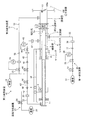
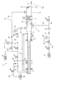
図1は、本実施形態に係る煤吹装置の概略図である。図2は、本実施形態に係る煤吹装置の要部拡大図である。 FIG. 1 is a schematic view of a soot blowing device according to the present embodiment. FIG. 2 is an enlarged view of a main part of the soot blower according to the present embodiment.
本実施形態の煤吹装置は、ガス化炉で代表される様な圧力容器100に設けられる。この圧力容器100は、図には明示しないが、内部に多数の内壁管を配置してガス通路を区画し、ガス通路には、ガスの流れに直交する方向に延びる多数の伝熱管の群(バンク)で形成した熱交換部を配置している。
The soot blowing apparatus of this embodiment is provided in a
煤吹装置は、筒状のケーシング1が圧力容器100の挿入穴100aを囲むように接続され、圧力容器100の外側に延在して設けられている。ケーシング1は、連結管2と、シールボックス4とを有している。
The soot blower is connected so that the
連結管2は、挿入穴100aから圧力容器100の内部に連通して設けられている。連結管2の設置位置は、水平方向で見て伝熱管の群が設置される位置のほぼ直下に相当し、後述する噴射管5が圧力容器100内に挿入されたとき、伝熱管の群に近接して対峙出来る位置を選択されている。この連結管2と圧力容器100の間であって圧力容器100の挿入穴100aの位置には、上端部を枢支されて常時は圧力容器100と連結管2とを遮蔽し、噴射管5の先端で押されて圧力容器100の内側に開かれる遮蔽扉13が設けられている。なお、遮蔽扉13の連結管2に対峙する面で、噴射管5の先端が当接する位置には、図示しないが、ころ部材が設けられており、噴射管5と遮蔽扉13は衝撃的に当接したり、摩擦接合したりすることのないように構成されている。
The connecting
連結管2において、圧力容器100から離れて向く外方端に、挿入遮断弁3が設けられている。挿入遮断弁3は、一方を連結管2の外方端に、他方をシールボックス4に接続して設置されている。挿入遮断弁3は、手動または自動で操作されて、連結管2とシールボックス4の間を連通または遮断する。
In the connecting
シールボックス4は、噴射管5が挿通されるように管状に形成されている。シールボックス4の挿入遮断弁3に接続された側を先端側といい、挿入遮断弁3に遠い側を後端側という。
The
噴射管5は、先端側が閉塞された筒状に形成され、その先端側に噴射孔5aを有している。噴射管5は、先端側がシールボックス4から挿入遮断弁3、連結管2を経て圧力容器100の内部を所定のストロークに亘って往復移動が可能に構成されている。噴射管5は、圧力容器100から遠い後端側に、モータ8により駆動される車輪9が設けられ、この車輪9が噴射管5の移動方向に対して平行に設けられた案内軌道10に沿って移動することで往復移動する。
The
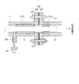
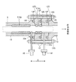
噴射管5は、シールボックス4の後端側および先端側において、グランドパッキン6および支持部7により往復移動に際して移動が案内されると共にシールボックス4との間の気密性が確保される。グランドパッキン6は、環状に形成されて、シールボックス4の内部の後端側に配置され、往復動する噴射管5を環状の内側によりシール状態で支持し、かつ、シールボックス4の内壁との間を環状の外側でシールするように構成されている。支持部7は、図2に示すように、環状に形成された内側で噴射管5の移動を案内する軸受7Aと、環状に形成された内側および外側でシールボックス4と噴射管5との間の気密性を確保する環状のシール材7Bと、を有する。
The movement of the
ここで、ケーシング1をなすシールボックス4は、図2に示すように、噴射管5の移動方向で複数(図2では2つ)に分割形成された分割ケーシング12を有している。各分割ケーシング12は、分割部分にフランジ12Aがそれぞれ形成され、各フランジ12Aが対向する間にボルテックスガスケット12Bなどのシール部材が挟まれた状態でボルト12Cにより連結される。支持部7は、圧力容器100寄りの分割ケーシング12に軸受7Aが設けられ、圧力容器100から遠い分割ケーシング12にシール材7Bが設けられている。
Here, as shown in FIG. 2, the
また、噴射管5の後方に、設置位置を固定されたガイド管11が設けられている。噴射管5は、後端側からガイド管11の先端側が挿通され、ガイド管11との間を密封した状態で、ガイド管11に対して自身の移動を許容するように嵌合されている。即ち、噴射管5とガイド管11は、相互に伸縮する二重パイプ構造となっている。
Further, a
上記構成において、煤吹装置は、蒸気供給装置21と、第一給気装置(給気装置)30と、第二給気装置41と、第三給気装置51と、を有する。
In the above configuration, the soot blowing device includes the
蒸気供給装置21は、噴射管5の後端側から突出されるガイド管11の後端側と、蒸気源22との間に蒸気ライン23が接続されている。蒸気ライン23は、遮断弁24が設けられている。従って、遮断弁24が開のときには、蒸気源22から蒸気ライン23を介して清掃用の蒸気(気体)がガイド管11そして噴射管5と供給されるようになっている。なお、蒸気ライン23は、遮断弁24の下流位置に逆止弁25が配置されているので、気体が蒸気源22側に逆流することはない。
In the
なお、図には明示しないが、噴射管5の移動経路に沿って複数のマイクロスイッチが設けられており、圧力容器100の内部に抜き挿しすべく移動する噴射管5の位置をマイクロスイッチにより検知し、噴射管5の位置に応じて蒸気の噴射開始や噴射停止を行う遮断弁24の開閉の作業指令が得られるようになっている。
Although not shown in the drawing, a plurality of microswitches are provided along the movement path of the
第一給気装置30は、ケーシング1のシールボックス4において支持部7の直近と、第一窒素ガス供給源31との間に第一窒素ガスライン32が接続されている。第一窒素ガスライン32は、遮断弁33が設けられている。第一窒素ガスライン32は、流量計34の検知信号に応じて自動的に開度調整を行う調整弁35が設けられると共に、当該調整弁35の下流位置に一定の絞り量に設定されたオリフィス36が設けられている。これにより、遮断弁33が開のときには、支持部7の直近に第一窒素ガス供給源31から圧力容器100の内部のガス圧力より高い圧力の窒素ガスが常時供給される。なお、第一窒素ガスライン32は、調整弁35の下流位置に逆止弁37が配置されているので、気体が第一窒素ガス供給源31側に逆流することはない。また、第一窒素ガス供給源31は、ガス化炉におけるバルブやフィルタのチャーなどの堆積物を除去するための窒素ガスを供給するものであり、第一給気装置30は、この第一窒素ガス供給源31を利用している。
In the first
ここで、第一給気装置30による供給する窒素ガスの圧力は、圧力容器100の内部のガス圧力に対する圧力差が、例えば、0.1MPa以上1.2MPa以下の範囲の圧力であって、例えば、圧力容器100の内部のガス圧力が2.7MPaである場合、2.8MPa以上3.9MPa以下の圧力を供給する。なお、第一給気装置30は、供給する窒素ガスの圧力を調整するにあたり、調整弁35またはオリフィス36の少なくとも一方を備えていればよい。
Here, the pressure of the nitrogen gas supplied by the first
この圧力の関係により、支持部7の直近に供給された窒素ガスは、支持部7より圧力容器100側に噴射管5が突出する部分に窒素ガスの噴流を生じさせる。
Due to this pressure relationship, the nitrogen gas supplied in the immediate vicinity of the
第二給気装置41は、ケーシング1のシールボックス4と、第一窒素ガス供給源31とは別の第二窒素ガス供給源42との間に第二窒素ガスライン43が接続されている。第二窒素ガスライン43は、遮断弁44が設けられている。また、第二窒素ガスライン43は、遮断弁44の下流側に、流量計45の検知信号に応じて自動的に開度調整を行う調整弁46が設けられると共に、当該調整弁46の下流位置に一定の絞り量に設定されたオリフィス47が設けられている。これにより、遮断弁44が開のときには、圧力容器100の内部のガス圧力より若干高い圧力の窒素ガスが常時供給される。なお、第二窒素ガスライン43は、遮断弁44の下流位置に逆止弁48が配置されているので、気体が第二窒素ガス供給源42側に逆流することはない。この第二給気装置41による供給する窒素ガスの圧力は、例えば、圧力容器100の内部のガス圧力2.7MPaに対して0.2MPa程度高い2.9MPaである。
In the second
また、第二給気装置41は、第二窒素ガスライン43が遮断弁44の上流位置で分岐して蒸気ライン23に連通する他の第二窒素ガスライン43’が設けられている。他の第二窒素ガスライン43’は、遮断弁44’および遮断弁44’の下流位置の逆止弁48’が設けられている。従って、蒸気供給装置21の遮断弁24が閉であって遮断弁44’が開のときには、第二窒素ガス供給源42から他の第二窒素ガスライン43’および蒸気ライン23を介してチャー除去用の窒素ガスがガイド管11そして噴射管5と供給されるようになっている。
In addition, the second
第三給気装置51は、第二窒素ガスライン43の遮断弁44(遮断弁44’)の上流位置とケーシング1である連結管2との間に第三窒素ガスライン53が設けられている。第三窒素ガスライン53は、流量計54の検知信号に応じて自動的に開度調整を行う調整弁55が設けられている。これにより、連結管2の内部に第二窒素ガス供給源42から圧力容器100の内部のガス圧力より高い圧力の窒素ガスが常時供給される。なお、第三窒素ガスライン53は、調整弁55の下流位置に逆止弁56が配置されているので、気体が第二窒素ガス供給源42側に逆流することはない。この第三給気装置51による供給する窒素ガスの圧力は、例えば、圧力容器100の内部のガス圧力2.7MPaに対して0.2MPa程度高い2.9MPaである。
In the third
このように構成された本実施形態の煤吹装置は、圧力容器100がガス化炉として機能する定常状態においては、圧力容器100内には、例えば、2.7MPaの高圧ガスが流れており、この時挿入遮断弁3は閉じられ、噴射管5は、図2に示す休止位置にあり、また遮断弁24,44,44’も閉じられた位置になっている。また、第一窒素ガスライン32も、圧力容器100がガス化炉として機能する定常状態において、遮断弁33が閉じられている。一方、第三窒素ガスライン53は、遮断弁が設けられておらず、調整弁55で調整されて圧力容器100内の高圧ガスの圧力をしのぐ、例えば、2.9MPaの窒素ガスが圧力容器100の作動中常時供給される。
In the soot blower of the present embodiment configured as described above, in a steady state where the
そして、1日に3〜4回程度の頻度で行われる伝熱管の清掃時には、遮断弁44が開かれ、シールガスとして約2.7MPaに調整された窒素ガスが第二窒素ガスライン43を経てシールボックス4に供給される。続いて、挿入遮断弁3が開かれ、モータ8が始動して噴射管5は連結管2を経て圧力容器100中に挿入され、所定位置で遮断弁24を開いて蒸気ライン23を経て噴射管5に蒸気を導入し、噴射孔5aから蒸気の噴射を開始し、噴射管5が所定位置で折り返して噴射開始の位置に戻るまで蒸気の噴射は続けられ、この戻った位置で遮断弁24を閉じて噴射が停止される。ここで、噴射管5が連結管2から圧力容器100中に挿入される際には、噴射管5は連結管2と圧力容器100の間に配置された遮蔽扉13をその先端で押し開いて前進する。
When the heat transfer tube is cleaned at a frequency of about 3 to 4 times a day, the shut-off
なお、遮断弁24が開いて蒸気の噴射が開始される少し前には、噴射管5の先端に設けた噴射孔5aが連結管2に挿入された段階で一時的に遮断弁44’が開き、他の第二窒素ガスライン43’から蒸気ライン23を経て窒素ガスが噴射管5内に供給され、当該噴射管5内に滞留している空気などをパージする。
Shortly before the
噴射管5による蒸気の噴射開始から停止に至る間の蒸気噴射により圧力容器100内の伝熱管の清掃作業が行われるが、この蒸気噴射の停止の後も噴射管5は引き続き圧力容器100から抜き出す移動を続ける。そして、噴射管5は、連結管2、挿入遮断弁3を出て休止位置に復位するが、この後退のタイミングに合わせて挿入遮断弁3が閉止位置に復位し、次いで遮断弁44も閉じ、かつ第三窒素ガスライン53を経て連結管2に窒素ガスが供給される元の状態に復位する。
Although the heat transfer tube in the
上記第二窒素ガスライン43を介した窒素ガスの供給の間、具体的には、噴射管5が移動する間であって、噴射管5が圧力容器100中に挿入される際、または噴射管5が圧力容器100から引き出される際、あるいは両方の際に、第一給気装置30の遮断弁33が開かれる。これにより、調整弁35で調整されて圧力容器100内の高圧ガスの圧力をしのぐ、例えば、2.8MPa以上3.9MPa以下の窒素ガスが第一窒素ガスライン32を経て支持部7の直近に供給される。
During the supply of nitrogen gas through the second
このように、本実施形態の煤吹装置は、圧力容器100の内部に熱交換器の伝熱管が配置されており、圧力容器100の内外に移動可能に設けられた噴射管5から伝熱管に向けて清掃用の蒸気を噴射する煤吹装置において、噴射管5が挿入される圧力容器100側の挿入穴100aを囲んで圧力容器100の外側に延在して設けられて内部に噴射管5が挿通される筒状のケーシング1と、ケーシング1の内部に設けられて噴射管5の移動を案内すると共にケーシング1と噴射管5との間の気密性を確保する支持部7と、支持部7の直近に配置されて圧力容器100側に噴射管5が突出する部分にガス(窒素ガス)の噴流を生じさせる第一給気装置30と、を備える。
As described above, in the soot blower of the present embodiment, the heat transfer tube of the heat exchanger is arranged inside the
この煤吹装置によれば、第一給気装置30により、圧力容器100側に噴射管5が突出する部分に窒素ガスの噴流を生じさせることで、支持部7から圧力容器100側に突出する噴射管5に噴射されたガスにより噴射管5の表面に付着したチャーが吹き飛ばされる。このため、煤吹するための噴射管5の表面に付着したチャーが支持部7のシール材7Bに取り込まれる事態を防止することができる。この結果、支持部7のシール材7Bの劣化が進行することを抑える効果を高めることができる。
According to this soot blowing device, the first
なお、第一給気装置30によって圧力容器100側に噴射管5が突出する部分に窒素ガスの噴流を生じさせる工程は、噴射管5の表面に付着したチャーを除去することが目的であり、噴射管5が移動している間のみ窒素ガスを供給する。窒素ガスの投入量は、ガス化炉ガス火炉の生成ガス発熱量の低下を抑える観点から少なくすることが好ましく、投入時間を短くすることが望ましいからである。
Note that the step of causing the first
ところで、図2では、第一給気装置30は、支持部7の直近であって、支持部7の後端側で窒素ガスを供給するように、第一窒素ガスライン32の先端が接続されるノズル32aが支持部7におけるシール材7Bの後端側に配置されている。この場合、ノズル32aから供給された窒素ガスは、支持部7と噴射管5との間の微小な隙間を通り、圧力容器100側に突出する噴射管5に噴流を生じさせる。詳細には、ノズル32aから供給された窒素ガスは、後端側のシール材7Bと噴射管5との間の微小な隙間を通過し、さらに先端側の軸受7Aと噴射管5との間の微小な隙間を通過して、圧力容器100側に突出する噴射管5に噴流を生じさせる。これにより、噴射管5の表面に付着したチャーが吹き飛ばされる。
By the way, in FIG. 2, the front end of the 1st
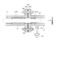
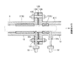
このノズル32aの配置は、上述した構成に限らない。図3および図4は、本実施形態に係る煤吹装置の他の例の要部拡大図であり、ノズル32aの別の配置を示している。
The arrangement of the
図3に示す形態では、第一給気装置30は、ノズル32aが、支持部7の直近であって、ノズル32aが支持部7における軸受7Aの先端側に配置されている。この場合、ノズル32aから供給された窒素ガスは、圧力容器100側に突出する噴射管5に直接噴流を生じさせる。詳細には、ノズル32aから供給された窒素ガスは、軸受7Aの先端側において、圧力容器100側に突出する噴射管5に噴流を生じさせる。これにより、噴射管5の表面に付着したチャーが吹き飛ばされる。
In the form shown in FIG. 3, in the first
図4に示す形態では、第一給気装置30は、ノズル32aが、支持部7の直近であって、ノズル32aが支持部7における軸受7Aの後端側および先端側に配置されている。この場合、ノズル32aから供給された窒素ガスは、一方では、軸受7Aと噴射管5との間の微小な隙間を通過して、圧力容器100側に突出する噴射管5に噴流を生じさせる。また、ノズル32aから供給された窒素ガスは、軸受7Aの先端側において、圧力容器100側に突出する噴射管5に噴流を生じさせる。これにより、噴射管5の表面に付着したチャーが吹き飛ばされる。
In the form shown in FIG. 4, in the first
このように、本実施形態の煤吹装置では、支持部7は、噴射管5の移動を案内する軸受7Aと、ケーシング1と噴射管5との間の気密性を確保するシール材7Bと、を有してシール材7Bの圧力容器100側に軸受7Aが配置されており、第一給気装置30は、軸受7Aを基準として圧力容器100側またはシール材7B側の少なくとも一方に給気する。
As described above, in the soot blower of the present embodiment, the
支持部7の軸受7Aは、噴射管5の移動を案内するものであり、気密性を確保するシール材7Bと比較して気密性が低い。このため、噴射管5の表面に付着したチャーは、軸受7Aを通過しやすい傾向にある。本実施形態の煤吹装置によれば、第一給気装置30は、軸受7Aを基準として圧力容器100側またはシール材7B側の少なくとも一方に給気する。従って、軸受7Aの先端側において、圧力容器100側に突出する噴射管5に効果的に噴流を生じさせる。これにより、軸受7Aを通過する以前に、噴射管5の表面に付着したチャーを吹き飛ばすことができる。
The
図5は、本実施形態に係る煤吹装置の追加例の概略図である。 FIG. 5 is a schematic view of an additional example of the soot blower according to the present embodiment.
本実施形態の煤吹装置では、第一給気装置30は、ケーシング1の外部に窒素ガスを排気する排気部を有する。排気部は、図5に示すように、第一窒素ガスライン32のオリフィス36より下流側で分岐して大気に開放された分岐ライン38と、分岐ライン38に設けられた遮断弁39とで構成される。
In the soot blower of the present embodiment, the first
即ち、排気部は、遮断弁39を開けることで、分岐ライン38を介して第一窒素ガスライン32の窒素ガスが排出される。これにより、ケーシング1の内部のガスが排気されるため、ケーシング1の支持部7など(支持部7の軸受7Aおよびシール材7Bやグランドパッキン6)のメンテナンス時におけるケーシング1の開放作業を安全に実施することができる。具体的には、メンテナンス開始時に、挿入遮断弁3と支持部7との間に残る圧力を確実に排気する。従って、排気部によりケーシング1の内部のガスが排気することで、ケーシング1の開放作業を安全に実施することができる。
That is, the exhaust unit opens the shut-off
図6および図7は、本実施形態に係る煤吹装置の他の例の要部拡大図である。 6 and 7 are enlarged views of main parts of another example of the soot blower according to the present embodiment.
図6に示すように、本実施形態の煤吹装置では、ケーシング1は、噴射管5の移動方向Xで複数(図6では4つ)に分割形成された分割ケーシング12を有している。各分割ケーシング12は、噴射管5の移動方向で互いに対向して接触する接触面12Dが形成され、対向する一方の接触面12Dで周方向に環状に形成されてシールリング12Eが収容される凹部12Fが形成されている。そして、各分割ケーシング12を噴射管5の移動方向Xでボルト12Gにて締結する。このため、対向する接触面12Dの接触が維持され、かつ凹部12Fに収容されたシールリング12Eが他方の接触面12Dに接触されて気密性が確保される。この分割ケーシング12に支持部7が設けられ、かつ、第一給気装置30のノズル32aが設けられる。
As shown in FIG. 6, in the soot blower of the present embodiment, the
より具体的に、分割ケーシング12に支持部7の軸受7Aとシール材7Bとがそれぞれ設けられ、かつ第一給気装置30のノズル32aが設けられる。
More specifically, the
なお、図6に示す形態では、第一給気装置30のノズル32aは、軸受7Aを基準として圧力容器100側およびシール材7B側に設けられているが、これに限定されない。ノズル32aは、軸受7Aを基準として圧力容器100側またはシール材7B側の少なくとも一方に設けられていればよい。また、図6に示す形態では、支持部7が軸受7Aとシール材7Bとに分けて形成されているが、支持部7が、噴射管5の移動を案内すると共にケーシング1と噴射管5との間の気密性を確保するように一体形成されている場合は、この一体形成の支持部7の先端側または後端側の少なくとも一方にノズル32aが設けられていればよい。
In the form shown in FIG. 6, the
このように構成された煤吹装置に係り、例えば、上述した図2〜図4に示す形態のように、ガスケット(ボルテックスガスケット)12Bをフランジ12A間に配置する場合、対向するフランジ12Aの面間がガスケット12Bの潰し代で変化するため、面間の差が噴射管5の軸心ズレに繋がることになる。噴射管5に軸心ズレが生じると、噴射管5が伝熱管に接触するおそれがある。
When the gasket (vortex gasket) 12B is disposed between the
この問題に対し、図6に示す形態は、噴射管5の移動方向Xである軸方向では、シールリング12Eが凹部12Fに収容された形態で各分割ケーシング12の各接触面12Dでシールリング12Eを挟み込むことなく各接触面12Dが接触するため、軸心ズレが低減され、かつシールリング12Eにより気密性が確保される。
With respect to this problem, in the form shown in FIG. 6, in the axial direction that is the moving direction X of the
また、本実施形態の煤吹装置では、図6に示すように、分割ケーシング12の少なくとも1つは、支持部7を設けられていないスペーサとして構成されることが好ましい。
Moreover, in the soot blowing apparatus of this embodiment, as shown in FIG. 6, it is preferable that at least 1 of the division |
即ち、メンテナンス時に支持部7を取り外す場合、スペーサとして構成した分割ケーシング12を抜くことで、作業スペースを確保することができ、メンテナンス作業を容易に行うことができる。
That is, when removing the
なお、煤吹装置において、噴射管5の軸心ズレを低減したり、メンテナンス作業を容易に行ったりする効果を得るうえで、第一給気装置30は必須ではない。従って、図7に示す形態の分割ケーシング12を備える構成とし、第一給気装置30のノズル32aを設けない構成であってもよい。
In the soot blowing device, the first
1 ケーシング
2 連結管
3 挿入遮断弁
4 シールボックス
5 噴射管
5a 噴射孔
6 グランドパッキン
7 支持部
7A 軸受
7B シール材
12 分割ケーシング
12D 接触面
12E シールリング
12F 凹部
12G ボルト
21 蒸気供給装置
22 蒸気源
23 蒸気ライン
24 遮断弁
25 逆止弁
30 第一給気装置
31 第一窒素ガス供給源
32 第一窒素ガスライン
32a ノズル
33 遮断弁
34 流量計
35 調整弁
36 オリフィス
37 逆止弁
38 分岐ライン
39 遮断弁
100 圧力容器
DESCRIPTION OF
Claims (9)
前記噴射管が挿入される前記圧力容器側の挿入穴を囲んで前記圧力容器の外側に延在して設けられて内部に前記噴射管が挿通される筒状のケーシングと、
前記ケーシングの内部に設けられて前記噴射管の移動を案内すると共に前記ケーシングと前記噴射管との間の気密性を確保する支持部と、
前記支持部の直近に配置されて前記圧力容器側に前記噴射管が突出する部分にガスの噴流を生じさせる給気装置と、
を備えることを特徴とする煤吹装置。 In the soot blowing device in which a heat transfer tube of a heat exchanger is arranged inside the pressure vessel and injects a cleaning gas from the injection tube movably provided inside and outside the pressure vessel toward the heat transfer tube,
A cylindrical casing that surrounds the insertion hole on the pressure vessel side into which the injection tube is inserted, extends outside the pressure vessel, and into which the injection tube is inserted;
A support portion provided inside the casing for guiding the movement of the injection pipe and ensuring airtightness between the casing and the injection pipe;
An air supply device that is arranged in the immediate vicinity of the support portion and generates a gas jet at a portion where the injection pipe protrudes toward the pressure vessel;
A soot blower characterized by comprising:
前記分割ケーシングに前記支持部が設けられ、かつ前記給気装置のノズルが設けられることを特徴とする請求項1〜3のいずれか1つに記載の煤吹装置。 The casing has a divided casing that is divided into a plurality of parts in the moving direction of the injection pipe, and each of the divided casings is formed with contact surfaces that face each other in the moving direction of the injection pipe, A concave portion is formed in which the seal ring that is annularly formed in the circumferential direction and is in contact with the other contact surface is accommodated in the one contact surface that faces.
The soot blower according to any one of claims 1 to 3, wherein the support portion is provided in the divided casing and a nozzle of the air supply device is provided.
各前記分割ケーシングに前記支持部の前記軸受と前記シール材とがそれぞれ設けられ、かつ前記給気装置のノズルが設けられることを特徴とする請求項2または3に記載の煤吹装置。 The casing has a divided casing that is divided into a plurality of parts in the moving direction of the injection pipe, and each of the divided casings is formed with contact surfaces that face each other in the moving direction of the injection pipe, A concave portion is formed in which the seal ring that is annularly formed in the circumferential direction and is in contact with the other contact surface is accommodated in the one contact surface that faces.
The soot blowing apparatus according to claim 2 or 3, wherein each of the divided casings is provided with the bearing of the support portion and the sealing material, and a nozzle of the air supply device.
前記噴射管が挿入される前記圧力容器側の挿入穴を囲んで前記圧力容器の外側に延在して設けられて内部に前記噴射管が挿通される筒状のケーシングと、
前記ケーシングの内部に設けられて前記噴射管の移動を案内すると共に前記ケーシングと前記噴射管との間の気密性を確保する支持部と、
を備え、
前記ケーシングは、前記噴射管の移動方向で複数に分割形成された分割ケーシングを有しており、各前記分割ケーシングは、前記噴射管の移動方向で互いに対向して接触する接触面が形成され、対向する一方の前記接触面で周方向に環状に形成されて他方の接触面に接触されるシールリングが収容される凹部が形成されており、
前記分割ケーシングに前記支持部が設けられることを特徴とする煤吹装置。 In the soot blowing device in which a heat transfer tube of a heat exchanger is arranged inside the pressure vessel and injects a cleaning gas from the injection tube movably provided inside and outside the pressure vessel toward the heat transfer tube,
A cylindrical casing that surrounds the insertion hole on the pressure vessel side into which the injection tube is inserted, extends outside the pressure vessel, and into which the injection tube is inserted;
A support portion provided inside the casing for guiding the movement of the injection pipe and ensuring airtightness between the casing and the injection pipe;
With
The casing has a divided casing that is divided into a plurality of parts in the moving direction of the injection pipe, and each of the divided casings is formed with contact surfaces that face each other in the moving direction of the injection pipe, A concave portion is formed in which the seal ring that is annularly formed in the circumferential direction and is in contact with the other contact surface is accommodated in the one contact surface that faces.
The soot blower characterized in that the support portion is provided in the divided casing.
各前記分割ケーシングに前記支持部の前記軸受と前記シール材とがそれぞれ設けられることを特徴とする請求項7に記載の煤吹装置。 The support portion includes a bearing that guides the movement of the injection pipe, and a seal material that ensures airtightness between the casing and the injection pipe, and the bearing is provided on the pressure vessel side of the seal material. Is placed,
The soot blower according to claim 7, wherein each of the divided casings is provided with the bearing of the support portion and the sealing material.
Priority Applications (4)
| Application Number | Priority Date | Filing Date | Title |
|---|---|---|---|
| JP2016079616A JP6345201B2 (en) | 2016-04-12 | 2016-04-12 | Soot blower |
| PCT/JP2017/012714 WO2017179420A1 (en) | 2016-04-12 | 2017-03-28 | Soot blowing apparatus |
| US16/084,355 US10962223B2 (en) | 2016-04-12 | 2017-03-28 | Soot blower |
| CN201780018247.8A CN108885078B (en) | 2016-04-12 | 2017-03-28 | Soot blower |
Applications Claiming Priority (1)
| Application Number | Priority Date | Filing Date | Title |
|---|---|---|---|
| JP2016079616A JP6345201B2 (en) | 2016-04-12 | 2016-04-12 | Soot blower |
Publications (3)
| Publication Number | Publication Date |
|---|---|
| JP2017190894A true JP2017190894A (en) | 2017-10-19 |
| JP2017190894A5 JP2017190894A5 (en) | 2018-02-01 |
| JP6345201B2 JP6345201B2 (en) | 2018-06-20 |
Family
ID=60041541
Family Applications (1)
| Application Number | Title | Priority Date | Filing Date |
|---|---|---|---|
| JP2016079616A Active JP6345201B2 (en) | 2016-04-12 | 2016-04-12 | Soot blower |
Country Status (4)
| Country | Link |
|---|---|
| US (1) | US10962223B2 (en) |
| JP (1) | JP6345201B2 (en) |
| CN (1) | CN108885078B (en) |
| WO (1) | WO2017179420A1 (en) |
Cited By (1)
| Publication number | Priority date | Publication date | Assignee | Title |
|---|---|---|---|---|
| CN111811167A (en) * | 2020-06-23 | 2020-10-23 | 倪浩 | An industrial evaporative condenser |
Families Citing this family (2)
| Publication number | Priority date | Publication date | Assignee | Title |
|---|---|---|---|---|
| CN110654941A (en) * | 2019-09-30 | 2020-01-07 | 大唐郓城发电有限公司 | Winding and unwinding devices for cooling tower condenser pipe based on thermal power factory |
| CN114135884B (en) * | 2021-11-30 | 2023-08-08 | 华能秦煤瑞金发电有限责任公司 | Blowing-out and soot blowing conversion device for secondary reheating tower furnace |
Citations (6)
| Publication number | Priority date | Publication date | Assignee | Title |
|---|---|---|---|---|
| JPS62112439U (en) * | 1986-01-08 | 1987-07-17 | ||
| JPH0460279A (en) * | 1990-06-29 | 1992-02-26 | Nippon Reinz Co Ltd | Seal ring and its assembling method |
| JPH06159650A (en) * | 1992-07-20 | 1994-06-07 | Babcock & Wilcox Co:The | Soot blower for self-adjusting packing gland |
| JPH0828853A (en) * | 1994-07-18 | 1996-02-02 | Kawasaki Heavy Ind Ltd | Soot blower device |
| WO2001007804A1 (en) * | 1999-07-23 | 2001-02-01 | Loy Yang Power Management Pty Ltd | Packing gland assembly for sootblowers |
| JP2003269887A (en) * | 2002-03-18 | 2003-09-25 | Mitsubishi Heavy Ind Ltd | Soot blower |
Family Cites Families (3)
| Publication number | Priority date | Publication date | Assignee | Title |
|---|---|---|---|---|
| CN1018856B (en) * | 1988-01-12 | 1992-10-28 | 上海船用柴油机研究所 | Movable tube row soot blower |
| CN101846325B (en) * | 2010-06-02 | 2012-08-22 | 中国石油化工集团公司 | Soot blower |
| CN103148491A (en) * | 2011-12-06 | 2013-06-12 | 中国石油化工股份有限公司 | Gas soot blower |
-
2016
- 2016-04-12 JP JP2016079616A patent/JP6345201B2/en active Active
-
2017
- 2017-03-28 WO PCT/JP2017/012714 patent/WO2017179420A1/en not_active Ceased
- 2017-03-28 US US16/084,355 patent/US10962223B2/en not_active Expired - Fee Related
- 2017-03-28 CN CN201780018247.8A patent/CN108885078B/en not_active Expired - Fee Related
Patent Citations (6)
| Publication number | Priority date | Publication date | Assignee | Title |
|---|---|---|---|---|
| JPS62112439U (en) * | 1986-01-08 | 1987-07-17 | ||
| JPH0460279A (en) * | 1990-06-29 | 1992-02-26 | Nippon Reinz Co Ltd | Seal ring and its assembling method |
| JPH06159650A (en) * | 1992-07-20 | 1994-06-07 | Babcock & Wilcox Co:The | Soot blower for self-adjusting packing gland |
| JPH0828853A (en) * | 1994-07-18 | 1996-02-02 | Kawasaki Heavy Ind Ltd | Soot blower device |
| WO2001007804A1 (en) * | 1999-07-23 | 2001-02-01 | Loy Yang Power Management Pty Ltd | Packing gland assembly for sootblowers |
| JP2003269887A (en) * | 2002-03-18 | 2003-09-25 | Mitsubishi Heavy Ind Ltd | Soot blower |
Cited By (1)
| Publication number | Priority date | Publication date | Assignee | Title |
|---|---|---|---|---|
| CN111811167A (en) * | 2020-06-23 | 2020-10-23 | 倪浩 | An industrial evaporative condenser |
Also Published As
| Publication number | Publication date |
|---|---|
| JP6345201B2 (en) | 2018-06-20 |
| US10962223B2 (en) | 2021-03-30 |
| CN108885078B (en) | 2020-09-22 |
| WO2017179420A1 (en) | 2017-10-19 |
| CN108885078A (en) | 2018-11-23 |
| US20190078779A1 (en) | 2019-03-14 |
Similar Documents
| Publication | Publication Date | Title |
|---|---|---|
| JP6345201B2 (en) | Soot blower | |
| US20120167547A1 (en) | Combustion turbine purge system and method of assembling same | |
| EP2574844A2 (en) | System for supplying pressured fluid to a cap assembly of a gas turbine combustor | |
| JP2011522990A (en) | Method for cleaning a fuel system of a gas turbine and the fuel system | |
| CN102016363B (en) | Seal assembly for use with pressurized container and method of assembling same | |
| EP2587023A2 (en) | System for turbine combustor fuel assembly | |
| US9476582B2 (en) | System and method for removing slag inside a utility furnace | |
| US9303870B2 (en) | System and method for injecting compound into utility furnace | |
| JP6258755B2 (en) | Fuel supply and cleaning equipment for gas engines | |
| JPS583166B2 (en) | Soot blower structure | |
| JP3702237B2 (en) | Soot blower | |
| US8424877B2 (en) | Method and system for sealing an annulus | |
| JP3702236B2 (en) | Soot blower | |
| JP4633980B2 (en) | Slag remover | |
| JP3917872B2 (en) | Soot blower for coal gasifier | |
| KR20220072639A (en) | Acoustic soot blower with variable frequency function | |
| KR102239239B1 (en) | Gas injection apparatus and method | |
| CN224050391U (en) | Waste gasification gas boiler with particulate matter purging device for incineration flue gas | |
| JPH08312799A (en) | Supply valve for injection medium | |
| KR100234222B1 (en) | Dry Pulverized Coal Feeding System for Coal Gasification Combined Cycle Power Plant | |
| JP2024078997A (en) | Burner, boiler and burner gun removal method | |
| TW202513172A (en) | Installation and method for cleaning interiors of receptacles and facilities | |
| JP2025077571A (en) | Apparatus and method for removing deposits | |
| JP2005186061A (en) | Apparatus for providing detonative cleaning communication and method for cleaning vessel | |
| JP2012057695A (en) | Dust removal device for fuel gas control valve |
Legal Events
| Date | Code | Title | Description |
|---|---|---|---|
| A521 | Request for written amendment filed |
Free format text: JAPANESE INTERMEDIATE CODE: A523 Effective date: 20171214 |
|
| A621 | Written request for application examination |
Free format text: JAPANESE INTERMEDIATE CODE: A621 Effective date: 20171214 |
|
| A871 | Explanation of circumstances concerning accelerated examination |
Free format text: JAPANESE INTERMEDIATE CODE: A871 Effective date: 20171214 |
|
| A975 | Report on accelerated examination |
Free format text: JAPANESE INTERMEDIATE CODE: A971005 Effective date: 20180123 |
|
| A131 | Notification of reasons for refusal |
Free format text: JAPANESE INTERMEDIATE CODE: A131 Effective date: 20180206 |
|
| A521 | Request for written amendment filed |
Free format text: JAPANESE INTERMEDIATE CODE: A523 Effective date: 20180404 |
|
| TRDD | Decision of grant or rejection written | ||
| A01 | Written decision to grant a patent or to grant a registration (utility model) |
Free format text: JAPANESE INTERMEDIATE CODE: A01 Effective date: 20180424 |
|
| A61 | First payment of annual fees (during grant procedure) |
Free format text: JAPANESE INTERMEDIATE CODE: A61 Effective date: 20180522 |
|
| R150 | Certificate of patent or registration of utility model |
Ref document number: 6345201 Country of ref document: JP Free format text: JAPANESE INTERMEDIATE CODE: R150 |
|
| S533 | Written request for registration of change of name |
Free format text: JAPANESE INTERMEDIATE CODE: R313533 |
|
| R350 | Written notification of registration of transfer |
Free format text: JAPANESE INTERMEDIATE CODE: R350 |
|
| R250 | Receipt of annual fees |
Free format text: JAPANESE INTERMEDIATE CODE: R250 |
|
| R250 | Receipt of annual fees |
Free format text: JAPANESE INTERMEDIATE CODE: R250 |
|
| R250 | Receipt of annual fees |
Free format text: JAPANESE INTERMEDIATE CODE: R250 |
|
| S111 | Request for change of ownership or part of ownership |
Free format text: JAPANESE INTERMEDIATE CODE: R313115 |
|
| R350 | Written notification of registration of transfer |
Free format text: JAPANESE INTERMEDIATE CODE: R350 |
|
| S111 | Request for change of ownership or part of ownership |
Free format text: JAPANESE INTERMEDIATE CODE: R313115 |
|
| R250 | Receipt of annual fees |
Free format text: JAPANESE INTERMEDIATE CODE: R250 |
|
| R350 | Written notification of registration of transfer |
Free format text: JAPANESE INTERMEDIATE CODE: R350 |
|
| R250 | Receipt of annual fees |
Free format text: JAPANESE INTERMEDIATE CODE: R250 |
|
| S531 | Written request for registration of change of domicile |
Free format text: JAPANESE INTERMEDIATE CODE: R313531 |
|
| S111 | Request for change of ownership or part of ownership |
Free format text: JAPANESE INTERMEDIATE CODE: R313117 |
|
| R350 | Written notification of registration of transfer |
Free format text: JAPANESE INTERMEDIATE CODE: R350 |
|
| R350 | Written notification of registration of transfer |
Free format text: JAPANESE INTERMEDIATE CODE: R350 |