JP2017190858A - Calibration device and method of electronic control type control valve - Google Patents
Calibration device and method of electronic control type control valve Download PDFInfo
- Publication number
- JP2017190858A JP2017190858A JP2016082280A JP2016082280A JP2017190858A JP 2017190858 A JP2017190858 A JP 2017190858A JP 2016082280 A JP2016082280 A JP 2016082280A JP 2016082280 A JP2016082280 A JP 2016082280A JP 2017190858 A JP2017190858 A JP 2017190858A
- Authority
- JP
- Japan
- Prior art keywords
- pressure
- pilot
- spool
- input
- pilot pressure
- Prior art date
- Legal status (The legal status is an assumption and is not a legal conclusion. Google has not performed a legal analysis and makes no representation as to the accuracy of the status listed.)
- Pending
Links
- 238000000034 method Methods 0.000 title claims abstract description 50
- 230000006837 decompression Effects 0.000 abstract description 3
- 238000005259 measurement Methods 0.000 abstract 2
- 239000012530 fluid Substances 0.000 description 10
- 238000006243 chemical reaction Methods 0.000 description 7
- 239000003921 oil Substances 0.000 description 7
- 238000006073 displacement reaction Methods 0.000 description 3
- 239000010720 hydraulic oil Substances 0.000 description 2
- 238000004519 manufacturing process Methods 0.000 description 2
- 238000004891 communication Methods 0.000 description 1
- 238000012790 confirmation Methods 0.000 description 1
- 230000008602 contraction Effects 0.000 description 1
- 238000001514 detection method Methods 0.000 description 1
- 238000010586 diagram Methods 0.000 description 1
- 230000000694 effects Effects 0.000 description 1
Images
Landscapes
- Operation Control Of Excavators (AREA)
- Indication Of The Valve Opening Or Closing Status (AREA)
Abstract
Description
本発明は、パイロット圧をスプールの両端に設けられたパイロット室に入力することでスプールを移動させる電磁弁を備えた電子制御式コントロール弁の較正装置およびその方法に関する。 The present invention relates to an electronically controlled control valve calibration apparatus and method therefor which includes an electromagnetic valve that moves a spool by inputting pilot pressure into pilot chambers provided at both ends of the spool.
一般に、例えば油圧ショベルなどの油圧式の作業機械は、油圧シリンダや油圧モータなどのアクチュエータに対して給排する作動油の流量や方向をコントロール弁によって制御している。このようなコントロール弁は、スプールと、このスプールをパイロット操作するリモコン弁とをアクチュエータ毎などに備えている。そして、オペレータによるレバーあるいはペダルなどの手動操作に応じて動作されたリモコン弁が、その操作量に応じてスプールの両端のパイロット室にパイロット圧を供給することにより、スプールが移動されて作動油の流路が開閉される。 In general, for example, a hydraulic working machine such as a hydraulic excavator controls the flow rate and direction of hydraulic oil supplied to and discharged from an actuator such as a hydraulic cylinder and a hydraulic motor by a control valve. Such a control valve includes a spool and a remote control valve for piloting the spool for each actuator. The remote control valve operated according to the manual operation of the lever or pedal by the operator supplies the pilot pressure to the pilot chambers at both ends of the spool according to the operation amount, so that the spool is moved and the hydraulic oil is The flow path is opened and closed.
リモコン弁としては、近年、レバー操作の操作量に応じて車載コントローラから出力された電気信号により動作されてパイロット2次圧を出力する電磁比例減圧弁などの電磁弁(電磁ソレノイドバルブ)である電油変換弁が用いられることがある。 In recent years, the remote control valve is an electromagnetic valve (electromagnetic solenoid valve) such as an electromagnetic proportional pressure reducing valve that is operated by an electric signal output from an in-vehicle controller in accordance with an operation amount of lever operation and outputs a pilot secondary pressure. An oil conversion valve may be used.
しかしながら、このような電油変換弁は、入力された電気信号に対するパイロット2次圧信号の入出力特性に製造公差、ヒステリシス特性などによるばらつきがあるため、電油変換弁の入力電気信号に対するコントロール弁のスプール変位にもばらつきが生じる。 However, since such an electro-oil conversion valve has variations due to manufacturing tolerances, hysteresis characteristics, etc., in the input / output characteristics of the pilot secondary pressure signal with respect to the input electric signal, the control valve for the input electric signal of the electro-oil conversion valve The spool displacement also varies.
そのため、指令電流値に対してスプールのストロークを計測し、公差外れの場合には較正値としてコントローラに記憶させる必要がある。そこで、電油変換弁への入力電気信号に対する出力パイロット圧力信号をゲージポートで測定して、電油変換弁の入出力特性を較正する技術が知られている(例えば、特許文献1参照。)。 For this reason, it is necessary to measure the spool stroke with respect to the command current value, and to store it in the controller as a calibration value if it is out of tolerance. Then, the technique which measures the output pilot pressure signal with respect to the input electric signal to an electro-oil conversion valve with a gauge port, and calibrates the input-output characteristic of an electro-oil conversion valve is known (for example, refer to patent documents 1). .
しかしながら、上述の構成の場合、電油変換弁のゲージポート1つずつに対してブルドン管などの圧力検出器を取り付け、圧力を測定する必要がある。電油変換弁は、スプール毎に一対設けられていることから、コントロール弁全体として数が多く、1つずつ手作業で較正を行うと時間を要し、作業者の負担が大きい。 However, in the case of the above-described configuration, it is necessary to measure the pressure by attaching a pressure detector such as a Bourdon tube to each gauge port of the electro-oil conversion valve. Since a pair of electro-oil conversion valves is provided for each spool, the number of control valves as a whole is large, and it takes time to perform calibration manually one by one, and the burden on the operator is large.
本発明は、このような点に鑑みなされたもので、短時間で容易に較正可能な電子制御式コントロール弁の較正装置およびその方法を提供することを目的とするものである。 The present invention has been made in view of these points, and an object of the present invention is to provide an electronic control type control valve calibration apparatus and method that can be easily calibrated in a short time.
請求項1記載の発明は、入力操作に応じた電気信号をパイロット圧に変換し、このパイロット圧をスプールの両端に設けられたパイロット室に入力することでスプールを移動させる電磁弁を備えた電子制御式コントロール弁の較正装置であって、スプールのパイロット室に入力されるパイロット圧をそれぞれ検出する圧力センサと、これら圧力センサと電気的に接続されるコントローラと、所定の電気信号により電磁弁からスプールのパイロット室に入力が想定される目標パイロット圧と、この電気信号をスプールの両端のパイロット室にパイロット圧を入力する対をなす電磁弁に対してそれぞれ入力させることで各パイロット室に対応する対をなす圧力センサにより検出されコントローラに入力される実測パイロット圧との比較結果に基づいて目標パイロット圧に対する実測パイロット圧の較正量を算出する算出部とを具備したものである。 According to the first aspect of the present invention, there is provided an electronic device comprising an electromagnetic valve that moves an spool by converting an electric signal corresponding to an input operation into a pilot pressure and inputting the pilot pressure into pilot chambers provided at both ends of the spool. A control device for calibrating a control type control valve, each of which detects a pilot pressure inputted to a pilot chamber of a spool, a controller electrically connected to these pressure sensors, and a solenoid signal by a predetermined electric signal The target pilot pressure that is assumed to be input to the pilot chamber of the spool and this electric signal are input to the respective solenoid valves that form a pair for inputting the pilot pressure to the pilot chamber at both ends of the spool, thereby corresponding to each pilot chamber. Based on the result of comparison with the actual pilot pressure detected by the paired pressure sensor and input to the controller Te is obtained; and a calculation unit for calculating a calibration amount of actual pilot pressure to the target pilot pressure.
請求項2記載の発明は、入力操作に応じた電気信号をパイロット圧に変換し、このパイロット圧をスプールの両端に設けられたパイロット室に入力することでスプールを移動させる電磁弁を備えた電子制御式コントロール弁の較正方法であって、所定の電気信号を一のスプールの両端のパイロット室にパイロット圧を入力する対をなす電磁弁に対してそれぞれ入力して、各パイロット室に入力するパイロット圧を実測し、所定の電気信号により電磁弁からスプールのパイロット室に入力が想定される目標パイロット圧と実測パイロット圧との比較結果に基づいて目標パイロット圧に対する実測パイロット圧の較正量を算出するものである。 According to a second aspect of the present invention, there is provided an electronic device comprising an electromagnetic valve that moves an spool by converting an electric signal corresponding to an input operation into a pilot pressure and inputting the pilot pressure into pilot chambers provided at both ends of the spool. A method for calibrating a control type control valve, wherein a predetermined electric signal is input to a pair of solenoid valves for inputting pilot pressure to pilot chambers at both ends of one spool, and the pilot is input to each pilot chamber. Measure the pressure, and calculate the calibration amount of the measured pilot pressure with respect to the target pilot pressure based on the comparison result between the target pilot pressure that is expected to be input from the solenoid valve to the pilot chamber of the spool and the measured pilot pressure by a predetermined electrical signal Is.
請求項1記載の発明によれば、所定の電気信号を一のスプールの両端のパイロット室にパイロット圧を入力する対をなす電磁弁に対してそれぞれ入力させて、圧力センサにより各パイロット室に入力するパイロット圧を実測してコントローラに入力し、所定の電気信号により電磁弁からスプールのパイロット室に入力が想定される目標パイロット圧と実測パイロット圧との比較結果に基づいて算出部が目標パイロット圧に対する実測パイロット圧の較正量を算出するので、全てのスプールを自動的に較正でき、短時間で容易に較正可能になる。また、スプールに対して両端の電磁弁により同圧が入力されるので、スプールが実質的に動かず、スプールの移動により動作される流体圧アクチュエータが実質的に動作しない状態で較正可能になるとともに、対をなす電磁弁を同時に較正可能となり、短時間での較正が可能となる。 According to the first aspect of the present invention, predetermined electric signals are respectively input to the pair of solenoid valves for inputting pilot pressure to the pilot chambers at both ends of one spool, and input to each pilot chamber by the pressure sensor. The pilot section is measured and input to the controller, and the calculator calculates the target pilot pressure based on the comparison result between the target pilot pressure expected to be input from the solenoid valve to the pilot chamber of the spool by a predetermined electrical signal and the measured pilot pressure. Since the calibration amount of the measured pilot pressure with respect to is calculated, all the spools can be automatically calibrated and can be easily calibrated in a short time. Further, since the same pressure is input to the spool by the solenoid valves at both ends, the spool can be calibrated in a state where the spool does not substantially move and the fluid pressure actuator operated by the movement of the spool does not substantially operate. The electromagnetic valves that make a pair can be calibrated at the same time, and calibration can be performed in a short time.
請求項2記載の発明によれば、所定の電気信号を一のスプールの両端のパイロット室にパイロット圧を入力する対をなす電磁弁に対してそれぞれ入力して、各パイロット室に入力するパイロット圧を実測し、所定の電気信号により電磁弁からスプールのパイロット室に入力が想定される目標パイロット圧と実測パイロット圧との比較結果に基づいて目標パイロット圧に対する実測パイロット圧の較正量を算出するので、パイロット圧を検出するための圧力センサおよびこの圧力センサの検出結果を入力するコントローラを用いることで全てのスプールを自動的に較正できるので、短時間で容易に較正可能になる。また、スプールに対して両端の電磁弁により同圧が入力されるので、スプールが実質的に動かず、スプールの移動により動作される流体圧アクチュエータが実質的に動作しない状態で較正可能になるとともに、対をなす電磁弁を同時に較正可能となり、短時間での較正が可能となる。 According to the second aspect of the present invention, a predetermined electric signal is input to each of the solenoid valves forming a pair for inputting the pilot pressure to the pilot chambers at both ends of one spool, and the pilot pressure input to each pilot chamber is input. And the calibration amount of the measured pilot pressure with respect to the target pilot pressure is calculated based on the comparison result between the target pilot pressure and the measured pilot pressure that are assumed to be input from the solenoid valve to the pilot chamber of the spool by a predetermined electrical signal. Since all the spools can be automatically calibrated by using the pressure sensor for detecting the pilot pressure and the controller for inputting the detection result of the pressure sensor, the calibration can be easily performed in a short time. Further, since the same pressure is input to the spool by the solenoid valves at both ends, the spool can be calibrated in a state where the spool does not substantially move and the fluid pressure actuator operated by the movement of the spool does not substantially operate. The electromagnetic valves that make a pair can be calibrated at the same time, and calibration can be performed in a short time.
以下、本発明を、図1乃至図6に示された一実施の形態に基いて詳細に説明する。 Hereinafter, the present invention will be described in detail based on one embodiment shown in FIGS.
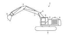
図3に示されるように、作業機械としての油圧ショベル1は、下部走行体2に上部旋回体3が旋回可能に設けられ、この上部旋回体3に、動力装置4、キャブ5および作業装置6などが搭載されている。作業装置6は、例えば上部旋回体3に上下動可能に軸支されたブーム7、このブーム7の先端に前後動可能に軸支されたスティック(アーム)8、および、このスティック8の先端に回動可能に軸支されたバケット9などを備える。
As shown in FIG. 3, a
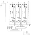
上部旋回体3上には、図2に示されるように電気信号に応じたストローク動作をする電子制御式コントロール弁11(以下、単にコントロール弁11という)が搭載されている。このコントロール弁11は、入力電流値などの電気信号に応じたパイロット圧力を出力する電磁弁である電磁比例減圧弁12a,12bと、これら電磁比例減圧弁12a,12bからのパイロット圧力により変位方向および変位量制御されるパイロット操作式のスプール13とを複数組備えている。
On the
電磁比例減圧弁12a,12bは、キャブ5(図3)内に設けられた電気ジョイスティックなどの操作器14が入力側に接続された第1のコントローラ(主コントローラ)としての車載コントローラ(MECM)15の出力側に接続されている。これら電磁比例減圧弁12a,12bは、各スプール13の両端にそれぞれ配置されている。そして、これら電磁比例減圧弁12a,12bは、車載コントローラ15からの入力電気信号に応じたパイロット圧力をスプール13に出力する。車載コントローラ15には、モニタ(図示せず)が接続されており、このモニタでは、車載コントローラ15から出力される各種情報を視覚的に表示するとともに、オペレータの各種設定操作が手動入力可能となっている。この車載コントローラ15には、後述する外部較正(外部キャリブレーション)モードが設定されている。
The electromagnetic proportional
複数のスプール13は、それぞれが、メインポンプ(図示せず)から下部走行体2(図3)の流体圧アクチュエータ(走行モータ)、上部旋回体3(図3)の流体圧アクチュエータ(旋回モータ)、作業装置6のブーム7、スティック8およびバケット9(図3)などを作動させる流体圧アクチュエータ(油圧シリンダ)に供給される作動油などの作動流体を方向制御および流量制御する。なお、図中では説明をより明確にするために、3個のスプール13のみを示す。
Each of the plurality of
このようなコントロール弁11の各スプール13の両端には(一端側および他端側)パイロット室13a,13bが設けられている。そして、両端のパイロット室13a,13bに作用するパイロット圧力を両端に配置された電磁比例減圧弁12a,12bによりそれぞれ制御することで、各スプール13が変位される。
また、ポンプとしてのパイロットポンプ21からタンク22に亘って、電磁比例減圧弁12a,12bにパイロット1次圧を供給するパイロット1次圧回路などへの通路25が設けられている。この通路25は、電磁比例減圧弁12a,12bにパイロット1次圧をそれぞれ供給するパイロット1次圧通路25aに分岐されている。
Further, a
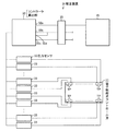
そして、このコントロール弁11は、図1に示される較正装置31により電磁比例減圧弁12a,12bを介してスプール13のパイロット室13a,13bに供給されるパイロット2次圧の入出力を較正可能となっている。較正装置31は、車載コントローラ15と異なるコントローラである第2のコントローラ(補助コントローラ)としての外部コントローラ(Ext−ECM)32と、複数の圧力センサ33とを備えている。
The
外部コントローラ32は、コネクタ35を介して車載コントローラ15および動力装置4(図3)のバッテリ(図示せず)と着脱可能に接続される。コネクタ35には、油圧ショベル1(図3)側の車載コントローラ15、バッテリおよびグランドがそれぞれ接続されて予め油圧ショベル1(図3)に備えられたサービスコネクタであり、外部コントローラ32には、コネクタ35に接続されることで油圧ショベル1(図3)側の車載コントローラ15、バッテリおよびグランドとそれぞれ電気的に接続される端子32a,32b,32cの他に、バッテリ用の端子32bと接続される端子32dとが設けられている。この端子32dは、例えば外部コントローラ32のキーポジション端子であり、バッテリから外部コントローラ32および圧力センサ33などへの給電のオンオフをキー操作により切り換えるためのものである。そして、この外部コントローラ32は、所定の通信プロトコルを用いて車載コントローラ15と通信し、この車載コントローラ15の動作を制御することでこの車載コントローラ15から電気信号をコントロール弁11の両端の電磁比例減圧弁12a,12bのソレノイドに入力させ、この入力された電気信号によりパイロット室13a,13bへの入力が想定される目標パイロット圧と、パイロット室13a,13bでの実測パイロット圧との比較結果(差)に基づいて、コントロール弁11の電磁比例減圧弁12a,12bの入出力の較正量を演算する算出部の機能を備えている。
The
圧力センサ33は、コントロール弁11の各接続タップTPと接続されるとともに外部コントローラ32と電気的に接続され、測定した圧力を外部コントローラ32に入力する。接続タップTPは、各スプール13のパイロット室13a,13bのいずれかとそれぞれ接続されており、電磁比例減圧弁12a,12bからパイロット室13a,13bに供給されるパイロット2次圧、すなわち電磁比例減圧弁12a,12bの出力圧を外部に取り出し、この接続タップTPに接続された圧力センサ33に出力可能となっている。なお、圧力センサ33は、接続タップTPと同数でもよいし、予備の流体圧アクチュエータなどに対応するスプール13用の接続タップTPなどに対応するために、接続タップTPより多く設けてもよい。
The
次に、図示された実施の形態の較正装置31を用いた較正方法を説明する。 Next, a calibration method using the calibration device 31 of the illustrated embodiment will be described.
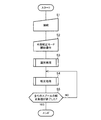
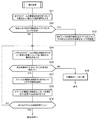
まず、この較正方法の概略を図4に示されるフローチャートも参照しながら説明する。
(ステップS1)
作業者は、較正装置31を用い、外部コントローラ32を、コネクタ35を介して車載コントローラ15、バッテリおよびグランドと手動で接続するとともに、各圧力センサ33を各接続タップTPに手動で接続する。
(ステップS2)
作業者は、手動操作により、車載コントローラ15に搭載された外部較正モードを開始させる。この外部較正モードは、例えばモニタから呼び出したサービスメニュー内で選択可能となっている。
(ステップS3)
バッテリからの電源の供給により起動された外部コントローラ32は、車載コントローラ15と通信し、外部較正モード用の電気信号を車載コントローラ15に入力することで、各スプール13と、このスプール13に対応する電磁比例減圧弁12a,12bの各接続タップTPに接続された各圧力センサ33との対応関係を識別する所定の識別処理を行う。この識別処理の詳細については後述する。
(ステップS4)
さらに、外部コントローラ32は、車載コントローラ15を介して電気信号を各スプール13の電磁比例減圧弁12a,12bのソレノイドに入力させ、圧力センサ33,33によりパイロット室13a,13bの圧力を検出することで所定の較正処理を行う。この較正処理の詳細についても後述する。
(ステップS5)
外部コントローラ32は、全てのスプール13に対応する電磁比例減圧弁12a,12bに対して較正処理が終了したか否かを判断する。このステップS5において、全てのスプール13に対応する電磁比例減圧弁12a,12bに対して較正処理が終了していないと判断した場合には、ステップS4に戻り、終了したと判断した場合には、外部較正モードを終了する。
First, an outline of this calibration method will be described with reference to the flowchart shown in FIG.
(Step S1)
The operator manually connects the
(Step S2)
The operator starts the external calibration mode mounted on the in-
(Step S3)
The
(Step S4)
Further, the
(Step S5)
The
次に、上記識別処理を図5に示されるフローチャートも参照しながら説明する。 Next, the identification process will be described with reference to the flowchart shown in FIG.
この識別処理では、各スプール13の電磁比例減圧弁12a,12bと圧力センサ33との対応関係の識別を可能な限り低圧で行う。
(ステップS11)
外部コントローラ32は、全てのスプール13の電磁比例減圧弁12a,12bのソレノイドに対して、パイロット室13a,13bの目標圧を0に設定する電気信号を、車載コントローラ15を介して入力させる。
(ステップS12)
外部コントローラ32は、各圧力センサ33により検出したパイロット室13a,13bの圧力のうち、0より大きい所定の閾値を超えているものがあるか否かを判断する。そして、所定の閾値を超えているものがあると判断した場合には、ステップS13に進み、所定の閾値を超えているものがないと判断した場合には、ステップS14に進む。
(ステップS13)
外部コントローラ32は、検出した圧力が所定の閾値を超えている圧力センサ33については、接続タップTPとの接続がされていない(接続不良となっている)ものと判断し、以降の外部較正モードの間、これら圧力センサ33からの出力を無視するように設定する。
(ステップS14)
外部コントローラ32は、いずれかのスプール13の両端の電磁比例減圧弁12a,12bに対して、パイロット室13a,13bの圧力を予め設定された所定の目標パイロット圧に設定する所定の電気信号を電磁比例減圧弁12a,12bのソレノイドに対して車載コントローラ15を介して入力させる。この対象となるスプール13は、識別処理を繰り返す毎に変えることで、全てのスプール13に対して識別処理を可能とする。電磁比例減圧弁12a,12bに対して、この目標パイロット圧と入力される電気信号の電流値あるいは電圧値との関係は、例えば外部コントローラ32にテーブル、あるいはグラフなどとして予め記憶されている。
(ステップS15)
外部コントローラ32は、所定時間(例えば5秒)以内に圧力センサ33により圧力を検出したか否かを判断する。そして、検出しないと判断した場合には、圧力センサ33を検出しないものと判断してステップS16に進み、検出したと判断した場合には、ステップS17に進む。
(ステップS16)
外部コントローラ32は、外部較正モードを中断する電気信号を車載コントローラ15に出力して、外部較正モードを終了する。
(ステップS17)
外部コントローラ32は、圧力センサ33からの出力に基づき、このスプール13の電磁比例減圧弁12a,12bと圧力センサ33との対応関係、すなわちどの接続タップTPにどの圧力センサ33が接続されているかを識別する。
(ステップS18)
外部コントローラ32は、このスプール13の電磁比例減圧弁12a,12bのソレノイドに対して、パイロット室13a,13bの目標圧を0に設定する電気信号を、車載コントローラ15を介して入力させる。
(ステップS19)
外部コントローラ32は、全てのスプール13に対して電磁比例減圧弁12a,12bと圧力センサ33と対応関係の識別が終了したか否かを判断する。そして、識別が終了していないと判断した場合には、ステップS14に進み、識別が終了したと判断した場合には、識別処理を終了する。
In this identification process, the correspondence relationship between the electromagnetic proportional
(Step S11)
The
(Step S12)
The
(Step S13)
The
(Step S14)
The
(Step S15)
The
(Step S16)
The
(Step S17)
Based on the output from the
(Step S18)
The
(Step S19)
The
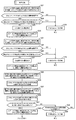
次に、上記較正処理を図6に示されるフローチャートも参照しながら説明する。 Next, the calibration process will be described with reference to the flowchart shown in FIG.
この較正処理では、概略として、目標パイロット圧が相対的に低圧側での較正量の算出(下記のステップS21乃至ステップS26)、目標パイロット圧が相対的に高圧側での較正量の算出(下記のステップS27乃至ステップS32)、および、各較正結果の確認(下記のステップS33乃至ステップS40)の各処理が順次行われる。
(ステップS21)
外部コントローラ32は、いずれか1つのスプール13の両端の電磁比例減圧弁12a,12bのソレノイドに対して、同一の所定の低圧側目標パイロット圧を設定する所定の電気信号である低圧側電気信号を、車載コントローラ15を介してそれぞれ入力させる。この対象となるスプール13は、較正処理を繰り返す毎に変えることで、全てのスプール13に対して較正処理を可能とする。電磁比例減圧弁12a,12bに対して、この低圧側目標パイロット圧と入力される電気信号の電流値あるいは電圧値との関係は、例えば外部コントローラ32にテーブル、あるいはグラフなどとして予め記憶されている。
(ステップS22)
所定時間経過後、外部コントローラ32は、圧力センサ33,33での検出圧力が予め設定された所定の低圧側許容範囲内であるか否かを判断する。いずれかの検出圧力が予め設定された所定の低圧側許容範囲内でないと判断した場合には、ステップS23に進み、各検出圧力がそれぞれ予め設定された所定の低圧側許容範囲内であると判断した場合には、ステップS24に進む。
(ステップS23)
外部コントローラ32は、外部較正モードを中断する電気信号を車載コントローラ15に出力して、外部較正モードを終了する。
(ステップS24)
外部コントローラ32は、両圧力センサ33,33の検出圧力の差圧が所定値(例えば400kPa)を超えているか否かを判断する。差圧が所定値を超えていると判断した場合には、スプール13が両端いずれかに移動して流体圧アクチュエータが動作するおそれがあるため、ステップS23に進む。差圧が所定値を超えていないと判断した場合には、ステップS25に進む。
(ステップS25)
外部コントローラ32は、低圧側目標パイロット圧と圧力センサ33,33の検出圧力との比較結果に基づき、低圧側の較正量を算出する。具体的に、低圧側目標パイロット圧と各圧力センサ33による実測パイロット圧との差圧を検出し、この差圧分を較正するための電磁比例減圧弁12a,12bへの電気信号の較正量を、予め記憶された電磁比例減圧弁12a,12bの入出力特性などに基づいて算出する。
(ステップS26)
外部コントローラ32は、スプール13の両端の電磁比例減圧弁12a,12bのソレノイドに対して目標圧を0に設定する電気信号を電磁比例減圧弁12a,12bに対して車載コントローラ15を介して入力させる。
(ステップS27)
外部コントローラ32は、上記スプール13の両端の電磁比例減圧弁12a,12bのソレノイドに対して、同一の所定の高圧側目標パイロット圧を設定する所定の電気信号である高圧側電気信号を、車載コントローラ15を介してそれぞれ入力させる。電磁比例減圧弁12a,12bに対して、この高圧側目標パイロット圧と入力される電気信号の電流値あるいは電圧値との関係は、例えば外部コントローラ32にテーブル、あるいはグラフなどとして予め記憶されている。
(ステップS28)
所定時間経過後、外部コントローラ32は、圧力センサ33,33での検出圧力が予め設定された所定の高圧側許容範囲内であるか否かを判断する。いずれかの検出圧力が予め設定された所定の高圧側許容範囲内でないと判断した場合には、ステップS29に進み、各検出圧力がそれぞれ予め設定された所定の高圧側許容範囲内であると判断した場合には、ステップS30に進む。
(ステップS29)
外部コントローラ32は、外部較正モードを中断する電気信号を車載コントローラ15に出力して、外部較正モードを終了する。
(ステップS30)
外部コントローラ32は、両圧力センサ33,33の検出圧力の差圧が所定値(例えば400kPa)を超えているか否かを判断する。差圧が所定値を超えていると判断した場合には、スプール13が両端いずれかに移動してアクチュエータが動作するおそれがあるため、ステップS29に進む。差圧が所定値を超えていないと判断した場合には、ステップS31に進む。
(ステップS31)
外部コントローラ32は、高圧側目標パイロット圧と圧力センサ33,33の検出圧力との比較結果に基づき、高圧側の較正量を算出する。具体的に、高圧側目標パイロット圧と各圧力センサ33による実測パイロット圧との差圧を検出し、この差圧分を較正するための電磁比例減圧弁12a,12bへの電気信号の較正量を、予め記憶された電磁比例減圧弁12a,12bの入出力特性などに基づいて算出する。
(ステップS32)
外部コントローラ32は、スプール13の両端の電磁比例減圧弁12a,12bに対して目標圧を0に設定する電気信号を電磁比例減圧弁12a,12bのソレノイドに対して車載コントローラ15を介して入力させる。
(ステップS33)
外部コントローラ32は、ステップS25で算出した低圧側の較正量を反映させた状態で、スプール13の両端の電磁比例減圧弁12a,12bのソレノイドに対して、上記所定の低圧側目標パイロット圧に設定する所定の低圧側電気信号を、車載コントローラ15を介して入力させる。
(ステップS34)
外部コントローラ32は、圧力センサ33,33での検出圧力が、予め設定された所定の低圧側許容公差内であるか否かを確認する。
(ステップS35)
外部コントローラ32は、ステップS31で算出した高圧側の較正量を反映させた状態で、スプール13の両端の電磁比例減圧弁12a,12bのソレノイドに対して、上記所定の高圧側目標パイロット圧に設定する所定の高圧側電気信号を、車載コントローラ15を介して入力させる。
(ステップS36)
外部コントローラ32は、圧力センサ33,33での検出圧力が、予め設定された所定の高圧側許容公差内であるか否かを確認する。
(ステップS37)
外部コントローラ32は、ステップS34またはステップS37において各許容公差内であると判断したか否かを判断する。ステップ34またはステップ37の少なくともいずれかで各許容公差内でないと確認したと判断した場合には、ステップS38に進み、各許容公差内であると判断した場合には、ステップS40に進む。
(ステップS38)
許容公差内でないと所定の複数回(例えば3回)以上判断したか否か判断する。所定の複数回以上でない(所定の複数回未満である)と判断した場合には、ステップS33に戻る。所定の複数回以上であると判断した場合には、外部較正モードのタイムアウトとしてステップS39に進む。
(ステップS39)
外部コントローラ32は、外部較正モードを中断する電気信号を車載コントローラ15に出力して、外部較正モードを終了する。
(ステップS40)
外部コントローラ32は、スプール13の両端の電磁比例減圧弁12a,12bに対して目標圧を0に設定する電気信号を電磁比例減圧弁12a,12bのソレノイドに対して車載コントローラ15を介して入力させ、較正処理を終了し、ステップS5へと進む。
In this calibration process, as a rule, the calculation of the calibration amount when the target pilot pressure is relatively low (steps S21 to S26 below), and the calculation of the calibration amount when the target pilot pressure is relatively high (see below). Steps S27 to S32) and confirmation of each calibration result (Steps S33 to S40 described below) are sequentially performed.
(Step S21)
The
(Step S22)
After elapse of a predetermined time, the
(Step S23)
The
(Step S24)
The
(Step S25)
The
(Step S26)
The
(Step S27)
The
(Step S28)
After a predetermined time has elapsed, the
(Step S29)
The
(Step S30)
The
(Step S31)
The
(Step S32)
The
(Step S33)
The
(Step S34)
The
(Step S35)
The
(Step S36)
The
(Step S37)
The
(Step S38)
If it is not within the permissible tolerance, it is determined whether or not a predetermined multiple times (for example, three times) have been determined. If it is determined that it is not more than a predetermined number of times (less than a predetermined number of times), the process returns to step S33. If it is determined that the number of times is greater than or equal to the predetermined number of times, the process proceeds to step S39 as a timeout in the external calibration mode.
(Step S39)
The
(Step S40)
The
次に、図1乃至図6に示された実施の形態の効果を説明する。 Next, effects of the embodiment shown in FIGS. 1 to 6 will be described.
外部コントローラ32から所定の電気信号(低圧側電気信号、あるいは高圧側電気信号)を一のスプール13の両端のパイロット室13a,13bにパイロット圧を入力する対をなす電磁比例減圧弁12a,12bに対してそれぞれ入力させて、圧力センサ33,33により各パイロット室13a,13bに入力するパイロット圧を実測し、所定の電気信号により電磁比例減圧弁12a,12bからスプール13のパイロット室13a,13bに入力が想定される目標パイロット圧と実測パイロット圧との比較結果に基づいて外部コントローラ32(算出部)が目標パイロット圧に対する実測パイロット圧の較正量を算出する。このため、全てのスプール13を自動的に較正できるので、各スプール13の電磁比例減圧弁12a,12bに対して順次手作業で較正量を算出する従来の場合と比較して、短時間での容易な較正が可能になる。また、スプール13に対して両端の電磁比例減圧弁12a,12bにより同圧が入力されるため、スプール13が実質的に動かず、したがってスプール13の移動により動作される流体圧アクチュエータが実質的に動作しない状態でより安全に較正可能になるとともに、油圧シリンダの伸び・縮み、あるいは走行モータや旋回モータの正転・逆転などのそれぞれに対応する2つの電磁比例減圧弁12a,12bを同時に較正可能となり、短時間での較正が可能となる。
A predetermined electrical signal (low pressure side electrical signal or high pressure side electrical signal) from the
特に、外部コントローラ32が算出部の機能を備えているので、車載コントローラ15に較正のための機能を予め備えていない油圧ショベル1に対しても、外部コントローラ32と圧力センサ33とからなる外付けの較正装置31を適用することで容易に自動較正可能となるだけでなく、作業者が手作業で外部コントローラ32および圧力センサ33を接続するだけで較正装置31を容易に設置でき、作業性および使い勝手が良好である。
In particular, since the
また、スプール13毎に、目標パイロット圧が相対的に低圧のときと相対的に高圧のときとで較正量をそれぞれ算出するので、より精度よく較正可能となる。
In addition, since the calibration amount is calculated for each
なお、上記一実施の形態において、外部較正モードは全てのスプール13に対して行う構成としたが、フィールドでの対応用として、少なくともいずれか1つの任意のスプール13のみを対象に行う機能を選択できるようにしてもよい。
In the above-described embodiment, the external calibration mode is configured to be performed for all spools 13. However, for the field response, a function for only at least one
また、低圧側と高圧側とで較正量を算出したが、1つの所定圧に対する較正量のみを算出することもできるし、3以上の所定圧に対する較正量を算出することもできる。 Further, although the calibration amount is calculated on the low pressure side and the high pressure side, only the calibration amount for one predetermined pressure can be calculated, or the calibration amount for three or more predetermined pressures can be calculated.
さらに、上記較正装置31および較正方法は、作業機械以外の電子制御式コントロール弁の較正にも一般的に利用可能である。 Furthermore, the calibration device 31 and the calibration method are generally applicable to calibration of electronically controlled control valves other than work machines.
また、上記較正方法は外部コントローラ32が車載コントローラ15を制御して行ったが、例えば車載コントローラ15が較正を実施し、外部コントローラ32は圧力センサ33からの圧力を送信するインターフェースとすることもできる。すなわち、算出部の機能は、車載コントローラ15に持たせてもよい。換言すれば、算出部の機能は、車載コントローラ15と外部コントローラ32との少なくともいずれかに備えることができる。この場合には、車載コントローラ15を較正装置31に含む。
Moreover, although the
本発明は、油圧ショベルなどの作業機械を製造、販売などする事業者、あるいは作業機械の保守管理をする事業者にとって産業上の利用可能性がある。 INDUSTRIAL APPLICABILITY The present invention has industrial applicability to businesses that manufacture and sell work machines such as hydraulic excavators or business operators that maintain and manage work machines.
11 電子制御式コントロール弁
12a,12b 電磁弁である電磁比例減圧弁
13 スプール
13a,13b パイロット室
31 較正装置
32 算出部の機能を備えるコントローラである外部コントローラ
33 圧力センサ
11 Electronic control valve
12a, 12b Solenoid proportional pressure reducing valve
13 Spool
13a, 13b Pilot room
31 Calibration device
32 External controller that is a controller with the function of the calculation unit
33 Pressure sensor
Claims (2)
スプールのパイロット室に入力されるパイロット圧をそれぞれ検出する圧力センサと、
これら圧力センサと電気的に接続されるコントローラと、
所定の電気信号により電磁弁からスプールのパイロット室に入力が想定される目標パイロット圧と、この電気信号をスプールの両端のパイロット室にパイロット圧を入力する対をなす電磁弁に対してそれぞれ入力させることで各パイロット室に対応する対をなす圧力センサにより検出されコントローラに入力される実測パイロット圧との比較結果に基づいて目標パイロット圧に対する実測パイロット圧の較正量を算出する算出部と
を具備したことを特徴とする電子制御式コントロール弁の較正装置。 An electronically controlled control valve calibration device equipped with an electromagnetic valve that moves the spool by converting the electrical signal corresponding to the input operation into a pilot pressure and inputting this pilot pressure into the pilot chambers provided at both ends of the spool. There,
A pressure sensor for detecting each pilot pressure input to the pilot chamber of the spool;
A controller electrically connected to these pressure sensors;
A target pilot pressure that is expected to be input from the solenoid valve to the pilot chamber of the spool by a predetermined electrical signal, and this electrical signal are input to a pair of solenoid valves that input the pilot pressure to the pilot chambers at both ends of the spool. A calculation unit for calculating a calibration amount of the actual pilot pressure with respect to the target pilot pressure based on a comparison result with the actual pilot pressure detected by the pair of pressure sensors corresponding to each pilot chamber and input to the controller. An electronically controlled control valve calibration apparatus characterized by the above.
所定の電気信号を一のスプールの両端のパイロット室にパイロット圧を入力する対をなす電磁弁に対してそれぞれ入力して、各パイロット室に入力するパイロット圧を実測し、
所定の電気信号により電磁弁からスプールのパイロット室に入力が想定される目標パイロット圧と実測パイロット圧との比較結果に基づいて目標パイロット圧に対する実測パイロット圧の較正量を算出する
ことを特徴とする電子制御式コントロール弁の較正方法。 An electronically controlled control valve calibration method that includes an electromagnetic valve that moves the spool by converting the electrical signal corresponding to the input operation into a pilot pressure and inputting this pilot pressure into the pilot chambers provided at both ends of the spool. There,
A predetermined electrical signal is input to each pair of solenoid valves that input pilot pressure to the pilot chambers at both ends of one spool, and the pilot pressure input to each pilot chamber is measured,
A calibration amount of the actual pilot pressure with respect to the target pilot pressure is calculated based on a comparison result between the target pilot pressure expected to be input from the solenoid valve to the pilot chamber of the spool by a predetermined electric signal and the actual pilot pressure. Electronic control valve calibration method.
Priority Applications (1)
| Application Number | Priority Date | Filing Date | Title |
|---|---|---|---|
| JP2016082280A JP2017190858A (en) | 2016-04-15 | 2016-04-15 | Calibration device and method of electronic control type control valve |
Applications Claiming Priority (1)
| Application Number | Priority Date | Filing Date | Title |
|---|---|---|---|
| JP2016082280A JP2017190858A (en) | 2016-04-15 | 2016-04-15 | Calibration device and method of electronic control type control valve |
Publications (1)
| Publication Number | Publication Date |
|---|---|
| JP2017190858A true JP2017190858A (en) | 2017-10-19 |
Family
ID=60084696
Family Applications (1)
| Application Number | Title | Priority Date | Filing Date |
|---|---|---|---|
| JP2016082280A Pending JP2017190858A (en) | 2016-04-15 | 2016-04-15 | Calibration device and method of electronic control type control valve |
Country Status (1)
| Country | Link |
|---|---|
| JP (1) | JP2017190858A (en) |
Cited By (7)
| Publication number | Priority date | Publication date | Assignee | Title |
|---|---|---|---|---|
| US11001989B1 (en) | 2020-03-30 | 2021-05-11 | Caterpillar Inc. | Electrical control of a hydraulic system |
| JP2021127793A (en) * | 2020-02-13 | 2021-09-02 | キャタピラー エス エー アール エル | Valve calibration system and calibration method |
| JP2023049997A (en) * | 2021-09-29 | 2023-04-10 | 日立建機株式会社 | Hydraulic shovel |
| WO2023227252A1 (en) * | 2022-05-27 | 2023-11-30 | Caterpillar Sarl | Calibration system in hydraulic system |
| WO2024080113A1 (en) * | 2022-10-14 | 2024-04-18 | 株式会社小松製作所 | Work machine and method for controlling work machine |
| WO2024080112A1 (en) * | 2022-10-14 | 2024-04-18 | 株式会社小松製作所 | Work machine and method for controlling work machine |
| EP4317708A4 (en) * | 2021-03-29 | 2025-01-22 | Xuzhou Xcmg Excavator Machinery Co., Ltd. | PILOT PROPORTIONAL CONTROL VALVE APPARATUS, AUTOMATIC CALIBRATION METHOD AND SUPPORT |
-
2016
- 2016-04-15 JP JP2016082280A patent/JP2017190858A/en active Pending
Cited By (13)
| Publication number | Priority date | Publication date | Assignee | Title |
|---|---|---|---|---|
| JP7431604B2 (en) | 2020-02-13 | 2024-02-15 | キャタピラー エス エー アール エル | Valve calibration system and method |
| JP2021127793A (en) * | 2020-02-13 | 2021-09-02 | キャタピラー エス エー アール エル | Valve calibration system and calibration method |
| CN115053075A (en) * | 2020-02-13 | 2022-09-13 | 卡特彼勒Sarl | Valve calibration system and calibration method |
| US11473271B2 (en) | 2020-03-30 | 2022-10-18 | Caterpillar Inc. | Electrical control of a hydraulic system |
| US11001989B1 (en) | 2020-03-30 | 2021-05-11 | Caterpillar Inc. | Electrical control of a hydraulic system |
| EP4317708A4 (en) * | 2021-03-29 | 2025-01-22 | Xuzhou Xcmg Excavator Machinery Co., Ltd. | PILOT PROPORTIONAL CONTROL VALVE APPARATUS, AUTOMATIC CALIBRATION METHOD AND SUPPORT |
| US12228152B2 (en) | 2021-03-29 | 2025-02-18 | Xuzhou Xcmg Excavator Machinery Co., Ltd | Pilot proportional control valve apparatus, automatic calibration method and medium |
| JP2023049997A (en) * | 2021-09-29 | 2023-04-10 | 日立建機株式会社 | Hydraulic shovel |
| JP7695168B2 (en) | 2021-09-29 | 2025-06-18 | 日立建機株式会社 | Hydraulic excavator |
| WO2023227252A1 (en) * | 2022-05-27 | 2023-11-30 | Caterpillar Sarl | Calibration system in hydraulic system |
| US12540634B2 (en) | 2022-05-27 | 2026-02-03 | Caterpillar Sarl | Calibration system in hydraulic system |
| WO2024080113A1 (en) * | 2022-10-14 | 2024-04-18 | 株式会社小松製作所 | Work machine and method for controlling work machine |
| WO2024080112A1 (en) * | 2022-10-14 | 2024-04-18 | 株式会社小松製作所 | Work machine and method for controlling work machine |
Similar Documents
| Publication | Publication Date | Title |
|---|---|---|
| JP2017190858A (en) | Calibration device and method of electronic control type control valve | |
| US20210156373A1 (en) | Calibration system for variable capacity hydraulic pump | |
| KR100641393B1 (en) | Hydraulic Control Circuit and Hydraulic Control Method | |
| EP1925825B1 (en) | Relief pressure switching apparatus for hydraulic working machine | |
| EP2660476B1 (en) | Fluid pressure circuit control apparatus and working machine | |
| US10508415B2 (en) | Swing control apparatus of construction equipment and control method thereof | |
| KR101801991B1 (en) | Out-of-range sensor recalibration | |
| US9458840B2 (en) | Relief pressure control device for hydraulic work machine | |
| US9366271B2 (en) | Slewing type construction machine | |
| US20180030687A1 (en) | Hydraulic speed modes for industrial machines | |
| CN109154153B (en) | Safety system for construction machine | |
| US11286647B2 (en) | Electrohydraulic control device for construction machine and method thereof | |
| US10119249B2 (en) | Control device for confluence flow rate of working device for construction machinery and control method therefor | |
| US20130213031A1 (en) | Hydraulic system for a construction machine | |
| US11199205B2 (en) | Construction machine | |
| JP4900671B2 (en) | Electronic control valve calibration device | |
| CN106640808A (en) | Hydraulic spool control circuit and method | |
| US20200240115A1 (en) | Electromagnetic valve identification device and control unit including same | |
| US12320372B2 (en) | Calibration system and calibration method in hydraulic system | |
| US11933331B2 (en) | Control device and hydraulic system including the same | |
| US12540634B2 (en) | Calibration system in hydraulic system | |
| EP3243965B1 (en) | Controlling an electric proportional valve | |
| JP2010203339A (en) | Method and device of controlling inclination, construction machine, and program for controlling inclination | |
| JPH03138469A (en) | Load sensing type hydraulic driving device | |
| JPWO1996027741A1 (en) | Hydraulic control device |