JP2017190845A - Anti-rest bracket - Google Patents
Anti-rest bracket Download PDFInfo
- Publication number
- JP2017190845A JP2017190845A JP2016081783A JP2016081783A JP2017190845A JP 2017190845 A JP2017190845 A JP 2017190845A JP 2016081783 A JP2016081783 A JP 2016081783A JP 2016081783 A JP2016081783 A JP 2016081783A JP 2017190845 A JP2017190845 A JP 2017190845A
- Authority
- JP
- Japan
- Prior art keywords
- holding member
- holding
- suspension
- fitting
- bolt
- Prior art date
- Legal status (The legal status is an assumption and is not a legal conclusion. Google has not performed a legal analysis and makes no representation as to the accuracy of the status listed.)
- Granted
Links
Images
Landscapes
- Mutual Connection Of Rods And Tubes (AREA)
- Vibration Prevention Devices (AREA)
Abstract
【課題】 電動工具のみで施工可能であるとともに、部品(パーツ)を分解することのない(外れない・脱落しない)施工現場での作業性・安定性に優れた振れ止め用金具を提供することにある。【解決手段】 振れ止め用金具10Aは、天井側から垂下された吊り部材80に固定される固定部材20Aと、天井側から傾斜して吊り部材80に取り付けられる振止部材90を保持する保持部材30Aと、を備える。また、固定部材20Aに対して保持部材30Aを振止部材90の傾斜角度に応じて回動自在に可動できるようにするため、固定部材20Aに回動自在に連結(リベット留め)されながら、保持部材30Aを取り付ける取付部材40Aを備える。そして、保持部材30Aが保持した振止部材90を取付部材40Aに取り付ける際に、締結具であるボルト71及びナット72を電動工具を使用して締結することができる。【選択図】 図2PROBLEM TO BE SOLVED: To provide a steady rest metal fitting that can be constructed with only an electric tool and that is excellent in workability and stability at a construction site where parts (parts) are not disassembled (does not come off or fall off). It is in. An anti-rest metal fitting 10A includes a fixing member 20A that is fixed to a suspension member 80 that is suspended from the ceiling side, and a holding member that is attached to the suspension member 80 while being inclined from the ceiling side. 30A. Further, in order to enable the holding member 30A to be rotatable with respect to the fixing member 20A according to the inclination angle of the anti-vibration member 90, the holding member 30A is held while being rotatably connected (riveted) to the fixing member 20A. An attachment member 40A for attaching the member 30A is provided. And when attaching the bracing member 90 held by the holding member 30A to the attachment member 40A, the bolt 71 and the nut 72, which are fasteners, can be fastened using an electric tool. [Selection] Figure 2
Description
本願発明は、空調機器や配管・架台等の支持材を支持するために天井側から垂下された全ネジ又は半ネジの吊り部材と、支持材を振れ止めするために天井側から傾斜して吊り部材に取り付けられる全ネジ又は半ネジの振止部材とを連結するための振れ止め用金具に関するものである。 The present invention includes a suspension member of full or half screws suspended from the ceiling side to support a support material such as an air conditioner, a pipe or a base, and a slanted suspension from the ceiling side to prevent the support material from swinging. The present invention relates to a steady-state fitting for connecting a full-screw or half-screw steady-state member attached to the member.
上記振れ止め用金具に関する先行技術文献としては、特許文献1に示すものが挙げられる。 As a prior art document relating to the above-mentioned metal fitting for steadying, the one shown in Patent Document 1 is cited.
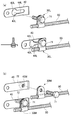
特許文献1は、図11に示すものである。詳しくは、吊りボルトPの側面に挟着する一対の挟着体1と、これら挟着体1の左右両端部を貫通して固定する一対の連結ボルト2と、この連結ボルト2に上下角度自在に連結され、吊りボルトPに対して斜めに配設される長ボルトQに連結する斜め支持体3とからなる。そして、ねじ山のピッチが異なる複数種類の吊りボルトPに対し、夫々ネジの上下2カ所の谷部に共通して食い込む上下一対の係止突起1Aを各挟着体1の内側面に設ける(連結片の境界部分に位置する湾曲面部に係止突起を設ける)ことを特徴とするものである。
Patent document 1 is shown in FIG. Specifically, a pair of sandwiching bodies 1 that are sandwiched between the side surfaces of the suspension bolt P, a pair of connecting bolts 2 that pass through and fix both the left and right ends of the sandwiching body 1, and the connecting bolt 2 can be freely tilted up and down. And an
上記する特許文献1など、これまで振れ止め用金具と呼ばれるものの多くは、次のような問題を有している。
(1)部品点数が非常に多い上に、個々の部材(パーツ)が分解されており、これを1つずつ組み立てていく必要があり、また、高所での作業となるため、部品落下の危険性もあった。
(2)例えば、斜めに配設される振止部材(特許文献1の長ボルトQ)などの固定には、電動工具(インパクトドライバー等)を使用できない部分もあるため、極めて煩雑な作業になっていた。
(3)全てのボルト・ナット締結前に、振止部材の角度調整が必要であった。
Many of the so-called steady rest fittings such as Patent Document 1 described above have the following problems.
(1) The number of parts is very large, and individual members (parts) are disassembled, and it is necessary to assemble them one by one. There was also danger.
(2) For example, there is a portion where an electric tool (impact driver or the like) cannot be used for fixing the bracing member (long bolt Q of Patent Document 1) disposed obliquely, which is extremely complicated work. It was.
(3) Before fastening all bolts and nuts, the angle adjustment of the bracing member was necessary.
これに対して、本願発明者は、電動工具のみで施工可能であるとともに、部品(パーツ)を分解することのない(外れない・脱落しない)施工現場での作業性・安定性に優れた振れ止め用金具を提供すべく鋭意試験・研究を行い、本願発明を完成するに至った。 On the other hand, the inventor of the present application can perform construction with only an electric tool, and has excellent workability and stability at a construction site where parts (parts) are not disassembled (does not come off or fall off). As a result of diligent testing and research to provide a stopper fitting, the present invention has been completed.
上記目的を達成するために、本願発明の第1の発明は、支持材を支持するために天井側から垂下された全ネジ又は半ネジの吊り部材と、支持材を振れ止めするために吊り部材と吊り部材の間に取り付けられる全ネジ又は半ネジの振止部材とを連結するための振れ止め用金具であって、吊り部材に固定される固定部材と、振止部材を保持する保持部材と、を備え、固定部材に対して保持部材を振止部材の傾斜角度に応じて回動自在に可動できることを特徴とした振れ止め金具である。
第2の発明は、固定部材に回動自在に連結されながら、保持部材を取り付ける取付部材を備えたことを特徴とした同振れ止め金具である。
第3の発明は、固定部材と取付部材との連結が、別途回動自在のための回動機構を備えたものであることを特徴した同振れ止め金具である。
第4の発明は、固定部材と保持部材とが一体、または、固定部材と取付部材とが一体、または、保持部材と取付部材とが一体であることを特徴とした同振れ止め金具である。
第5の発明は、保持部材が、振止部材を握持する握持部と、握持部から延伸するとともにこれを近接させることで握持部を緊締する一対の延伸部とを備えることを特徴とした同振れ止め金具である。
第6の発明は、保持部材が、取付部材に対して回動自在に取り付けられることを特徴とした同振れ止め金具である。
第7の発明は、取付部材が、保持部材と当接する当接片を備えたことを特徴とする同振れ止め金具である。
第8の発明は、固定部材が、ボルト及びナットを螺合させたままの状態で吊り金具に固定されることを特徴とする同振れ止め金具である。
In order to achieve the above object, the first invention of the present invention is a suspension member of a full screw or a half screw suspended from the ceiling side for supporting the support member, and a suspension member for swinging the support member An anti-rest fitting for connecting a full-screw or half-screw anti-vibration member attached between the suspension member and a suspension member, a fixing member fixed to the suspension member, and a holding member for holding the anti-vibration member; , And the holding member can be pivotably moved with respect to the fixed member in accordance with the inclination angle of the steadying member.
According to a second aspect of the present invention, there is provided the anti-stabilization bracket comprising an attachment member for attaching the holding member while being rotatably connected to the fixing member.
According to a third aspect of the present invention, there is provided the anti-swaying bracket characterized in that the connection between the fixing member and the mounting member is provided with a rotation mechanism for freely rotating.
According to a fourth aspect of the present invention, there is provided the anti-sway fitting, wherein the fixing member and the holding member are integrated, the fixing member and the mounting member are integrated, or the holding member and the mounting member are integrated.
According to a fifth aspect of the present invention, the holding member includes a gripping portion that grips the anti-vibration member and a pair of extending portions that extend from the gripping portion and tighten the gripping portion by bringing the holding member close to each other. This is the same steady rest bracket.
A sixth aspect of the present invention is the steady rest fitting, wherein the holding member is rotatably attached to the attachment member.
According to a seventh aspect of the present invention, there is provided the anti-sway fitting, wherein the mounting member includes a contact piece that contacts the holding member.
An eighth invention is a steady rest fitting, wherein the fixing member is fixed to the suspension fitting in a state where the bolt and the nut are screwed together.
上記した本願発明によれば、以下のような効果を有する。
(1)本願発明は、振止部材を保持する保持部材を備えることで、電動工具のみで施工が可能となり、作業効率が飛躍的に向上するとともに、均一な施工品質を確保できる。
(2)本願発明は、部品(パーツ)を分解することがないので、施工現場での作業効率が向上し、部品落下が防止できる。
(3)本願発明は、取付部材を備えることで、振止部材の調整代を余分に設けることができる。それにより、吊り部材の端部(駆体・吊り下げ機器)のごく近傍に固定部材を取り付けることができる。また、取付部材分の調整代があることにより、施工前に予め用意する振止部材の長さの許容範囲が広くなる。
(4)本願発明は、固定部材に対して保持部材又は/及び取付部材を振止部材の傾斜角度に応じて回動自在に可動できることで、振止部材を取り付け後も相手側を取り付けるまで角度調整が可能になる。
(5)なお、以上の効果は新設の場合の他に、既設装置に対して設置する際に有利であり(落ちない・電動工具のみ・角度自由)、作業性に極めて優れたものとなっている。
According to the present invention described above, the following effects are obtained.
(1) By providing the holding member that holds the bracing member according to the present invention, it is possible to perform the construction with only the electric tool, and the working efficiency can be dramatically improved and the uniform construction quality can be ensured.
(2) Since this invention does not decompose | disassemble components (parts), the working efficiency in a construction site improves and it can prevent components fall.
(3) This invention can provide the adjustment allowance of a bracing member extra by providing an attachment member. Thereby, a fixing member can be attached in the very vicinity of the edge part (driving body and suspension apparatus) of a suspension member. Moreover, since there is an adjustment allowance for the mounting member, the allowable range of the length of the bracing member prepared in advance before construction is widened.
(4) In the present invention, the holding member or / and the mounting member can be rotated with respect to the fixed member in accordance with the inclination angle of the anti-rest member so that the other side is attached even after the anti-reflection member is attached. Adjustment is possible.
(5) In addition to the case of new installation, the above effects are advantageous when installing on existing equipment (does not fall, only power tools, free angle), and extremely excellent workability. Yes.
本願発明の実施形態を図面に基づいて説明する。
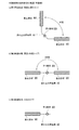
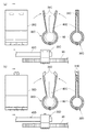
図1は、本願発明に係る振れ止め用金具の実施形態を示す略図である。
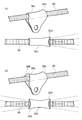
図1(a)は、第1実施形態の略図であり、振れ止め用金具10が吊り部材80に対して90度の角度で交差する2本の振止部材90,90を連結する「両側90度タイプ」のものである。
図1(b)は、第2実施形態の略図であり、振れ止め用金具10が吊り部材80に対して180度の角度で交差する2本の振止部材90,90を連結する「両側180度タイプ」のものである。
図1(c)は、第3実施形態の略図であり、振れ止め用金具10が吊り部材に対して1本の振止部材90,90を連結する「片側タイプ」のものである。
以下、図2〜図4において、上記第1実施形態〜第3実施形態を詳しく説明する。なお、図示のものは本願発明の例示で有り、これらに限定されるものではない(例えば、両側135度タイプなど)。
Embodiments of the present invention will be described with reference to the drawings.
FIG. 1 is a schematic view showing an embodiment of a steady rest fitting according to the present invention.
FIG. 1A is a schematic diagram of the first embodiment, in which the steadying bracket 10 connects two
FIG. 1B is a schematic diagram of the second embodiment, in which the steady-state bracket 10 connects two
FIG. 1C is a schematic diagram of the third embodiment, and is a “one-sided type” in which the steadying fitting 10 connects one
Hereinafter, the first to third embodiments will be described in detail with reference to FIGS. In addition, the thing of illustration is an illustration of this invention, and is not limited to these (For example, both sides 135 degree type etc.).
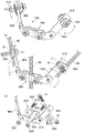
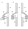
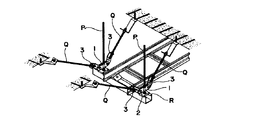
図2は、本願発明に係る振れ止め用金具の第1実施形態(両側90度タイプ)を示す説明図である。
図2(a)及び(b)に示すように、振れ止め用金具10Aは、天井側から垂下された吊り部材80に固定される固定部材20Aと、天井側から傾斜して吊り部材80に取り付けられる振止部材90を保持する保持部材30Aと、を備える。また、固定部材20Aに対して保持部材30Aを振止部材90の傾斜角度に応じて回動自在に可動できるようにするため、固定部材20Aに回動自在に連結(図示はリベット留め)されながら、保持部材30Aを取り付ける取付部材40Aを備える。
FIG. 2 is an explanatory view showing a first embodiment (both
As shown in FIGS. 2 (a) and 2 (b), the
そして、保持部材30Aが保持した振止部材90を取付部材40Aに取り付ける際に、締結具であるボルト71及びナット72を電動工具を使用して締結することができる。
また、この時、保持部材30Aにボルト71の共回り防止手段を設けるとともに、ボルト71のネジ部にナット72の打痕等の脱落防止手段を設けるとよい(他の実施形態においても同様である)。これにより、部品(パーツ)を分解することがないので、施工現場での作業が安定する。
さらに、取付部材40Aの先端をL字形に折り曲げた折曲部41Aを備えることで、フリーな状態にある保持部材30Aがこの折曲部41Aに当接し、確実に係止される(場所が決まる)。
And when attaching the
At this time, the
Furthermore, by providing the
図2(c)に示すように、固定部材20Aは、一方の固定片21Aに切欠溝22Aと係止突起23Aを備えることで、ボルト61A及びナット62Aを螺合させたままの状態で吊り金具に固定できるので、部品(パーツ)を分解することがなく、施工現場での作業が安定する(以下の第2実施形態及び第3実施形態においても同じ)。なお、固定片21Aに設けられている切欠溝22Aと係止突起23Aは、固定片21Aの対となるもう一方の固定片に設けられても同様となる(以下の第2実施形態及び第3実施形態においても同じ)。
As shown in FIG. 2 (c), the fixing
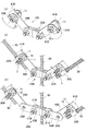
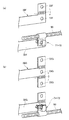
図3は、本願発明に係る振れ止め用金具の第2実施形態(両側180度タイプ)を示す説明図である。
図3(a)及び(b)に示すように、振れ止め用金具10Bは、天井側から垂下された吊り部材80に固定される固定部材20Bと、天井側から傾斜して吊り部材80に取り付けられる振止部材90を保持する保持部材30Bと、を備える。また、固定部材20Bに対して保持部材30Bを振止部材90の傾斜角度に応じて回動自在に可動できるようにするため、固定部材20Bに回動自在に連結(ボルト・ナット留め)されながら、保持部材30Bを取り付ける取付部材40Bを備える。
FIG. 3 is an explanatory view showing a second embodiment (180 degrees on both sides) of the steady rest fitting according to the present invention.
As shown in FIGS. 3 (a) and 3 (b), the anti-rest fitting 10B is fixed to the
そして、保持部材30Bが保持した振止部材90を取付部材40Bに取り付ける際に、締結具であるボルト71及びナット72を電動工具を使用して締結することができる。
また、取付部材40Bの先端をL字形に折り曲げた折曲部41Bを備えることで、フリーな状態にある保持部材30Bがこの折曲部41Bに当接し、確実に係止される(場所が決まる)。
And when attaching the
Further, by providing the
図3(c)に示すように、固定部材20Bは、一方の固定片21Bにボルト61B及びナット62Bとは別に回動自在のための回動機構(図示ではリベット25B)で取付部材40Bを回動自在に連結してもよい(次の第3実施形態においても同じ)。
As shown in FIG. 3 (c), the fixing
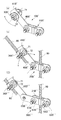
図4は、本願発明に係る振れ止め用金具の第3実施形態(片側タイプ)を示す説明図である。
図4に示すように、振れ止め用金具10B’は、天井側から垂下された吊り部材80に固定される固定部材20B’と、天井側から傾斜して吊り部材80に取り付けられる振止部材90を保持する保持部材30B’と、を備える。また、固定部材20B’に対して保持部材30B’を振止部材90の傾斜角度に応じて回動自在に可動できるようにするため、固定部材20B’に回動自在に連結(ボルト・ナット留め)されながら、保持部材30B’を取り付ける取付部材40B’を備える。
FIG. 4 is an explanatory view showing a third embodiment (one-sided type) of the steady rest fitting according to the present invention.
As shown in FIG. 4, the steadying metal fitting 10 </ b> B ′ includes a fixing member 20 </ b> B ′ that is fixed to a
そして、保持部材30B’が保持した振止部材90を取付部材40B’に取り付ける際に、締結具であるボルト71及びナット72を電動工具を使用して締結することができる。
また、取付部材40B’の先端をL字形に折り曲げた折曲部41B’を備えることで、フリーな状態にある保持部材30B’がこの折曲部41B’に当接し、確実に係止される(場所が決まる)。
Then, when attaching the bracing
Further, by providing the
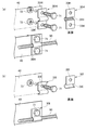
図5は、振れ止め用金具の保持部材の構造を示す説明図(1)である。
図5は、保持部材30が保持した振止部材90を取付部材40に取り付けるに際して、ボルト・ナットを使用せずに取り付けられる構造にしたものである。
図5(a)に図示する保持部材30Cは、オス・メスの嵌合構造31Cで取付部材40Cに取り付ける構造になっている。
図5(b)に図示する保持部材30Dは、つまみを交差させた嵌合構造31Dで取付部材40Dに取り付ける構造になっている。そして、このつまみ部分に応力をかけることで簡単に嵌合状態を解消できる。
FIG. 5 is an explanatory view (1) showing the structure of the holding member of the steady rest metal fitting.
FIG. 5 shows a structure in which the bracing
The holding
The holding
図6は、振れ止め用金具の保持部材の構造を示す説明図(2)である。
図6は、保持部材30が保持した振止部材90を取付部材40に取り付けるに際して、ボルト・ナットを使用せずに取り付けられる構造にしたものである。
具体的には、図6に図示するように、保持部材30Eにフック構造32Eを備えて振止部材90を取付部材40(図示省略)に取り付ける。
FIG. 6 is an explanatory view (2) showing the structure of the holding member of the steady rest metal fitting.
FIG. 6 shows a structure in which the
Specifically, as shown in FIG. 6, the holding member 30 </ b> E is provided with a hook structure 32 </ b> E, and the
図7は、振れ止め用金具の保持部材の構造を示す説明図(3)である。
図7は、保持部材30を取付部材と一体化構造にしたものである。
図7(a)に図示する保持部材30FはL字形をしており、その突片で振止部材90を巻き付けた上で、ボルト孔33F,33Fを介してボルト71及びナット72で締結するものである。なお、保持部材30Fは固定部材20に回動可能に連結されている。
図7(b)に図示する保持部材30GはT字形をしており、そのいずれかの突片で振止部材90を巻き付けた上で、ボルト孔33G,33Gを介してボルト71及びナット72で締結するものである。なお、保持部材30Gは固定部材20に回動可能に連結されている。
この際予め、振止部材90を巻き付ける部分を丸く加工しておき、ボルト71・ナット72を取り付けて、且つボルト71にナット72の脱落防止手段を施すことで分解作業は不要となる。
なお、一体化構造には、図7に図示するものの他に、部材どうしが固定されているような場合、例えば、取付部材に保持部材が溶接等によって固定されているような場合も含む。
FIG. 7 is an explanatory view (3) showing the structure of the holding member of the steady rest metal fitting.
FIG. 7 shows a structure in which the holding member 30 is integrated with the mounting member.
The holding
The holding
At this time, the part around which the
In addition to the one shown in FIG. 7, the integrated structure includes a case where the members are fixed, for example, a case where the holding member is fixed to the mounting member by welding or the like.
図8は、振れ止め用金具の保持部材の構造を示す説明図(4)である。
図8は、保持部材30を固定式のサドルバンドの構造にしたものである。
図8(a)に図示する保持部材30Hはボルト孔33Hを2箇所備えた両サドルバンドであり、振止部材90を湾曲部34Hに通し、ボルト孔33H,33Hを介してボルト71及びナット72で締結し、取付部材40に取り付ける。
図8(b)に図示する保持部材30Iはボルト孔33Iを1箇所備えた片サドルバンドであり、振止部材90を湾曲部34Iに通し、ボルト孔33Iを介してボルト71及びナット72で締結し、取付部材40に取り付ける。
この際ボルト71にナット72の脱落防止手段を施し、振止部材90を差し込むようにすると、分解作業は不要となる。
FIG. 8 is an explanatory view (4) showing the structure of the holding member of the steady rest metal fitting.
FIG. 8 shows the holding member 30 having a fixed saddle band structure.
A holding
The holding member 30I shown in FIG. 8B is a single saddle band provided with one bolt hole 33I, and the bracing
At this time, if the
図9は、振れ止め用金具の保持部材の構造を示す説明図(5)である。
図9は、保持部材30を長手方向から挿入しやすい構造にしたものである。
図9(a)に図示する保持部材30Jは振止部材90を挿入する挿入口35Jの片側をフレア型にして、振止部材90の長手方向からの挿入を容易にした。
図9(b)に図示する保持部材30Kは振止部材90を挿入する挿入口35Kの両側をフレア型にして、振止部材90の長手方向からの挿入を容易にした。
FIG. 9 is an explanatory view (5) showing the structure of the holding member of the steady rest metal fitting.
FIG. 9 shows a structure in which the holding member 30 can be easily inserted from the longitudinal direction.
In the holding
In the holding
図10は、振れ止め用金具の保持部材の構造を示す説明図(6)である。
図10は、保持部材30を取付部材40に横から取付可能な構造にしたものである。
図10に図示するように、保持部材30Lは振止部材90を保持した上で、取付部材40Lに形成されたダルマ穴42Lの拡径部分43Lにナット72又はボルト71を通し、縮径部分44Lにスライドさせて取り付けるものである。
FIG. 10 is an explanatory view (6) showing the structure of the holding member for the steady rest metal fitting.
FIG. 10 shows a structure in which the holding member 30 can be attached to the
As shown in FIG. 10, the holding
本願発明に係る振れ止め用金具は、空調機器や配管・架台等の支持材を支持するために天井側から垂下された吊り部材(全ネジ・半ネジ)と、支持材を振れ止めするために天井側から傾斜して吊り部材に取り付けられる振止部材(全ネジ・半ネジ)とを連結するために広く利用できるものである。特に、既に吊り部材や振止部材が配設された場合の後付け施工が可能な振れ止め用金具として広く利用できるものである。 The steady rest bracket according to the invention of the present application is for suspension members (full screws and half screws) suspended from the ceiling side to support the support materials such as air conditioners, pipes and mounts, and the support materials It can be widely used to connect a bracing member (full screw / half screw) that is inclined from the ceiling side and attached to the suspension member. In particular, it can be widely used as an anti-rest fitting that can be retrofitted when a suspension member or anti-rest member is already provided.
10 振れ止め用金具
20 固定部材
30 保持部材
31 嵌合構造
32 フック構造
33 ボルト孔
34 湾曲部
35 挿入口
40 取付部材
41 折曲部
42 ダルマ穴
43 拡径部分
44 縮径部分
45 ボルト孔
71 ボルト
72 ナット
80 吊り部材
90 振止部材
DESCRIPTION OF SYMBOLS 10 Stabilizing metal fitting 20 Fixing member 30 Holding member 31 Fitting structure 32 Hook structure 33 Bolt hole 34 Bending part 35
本願発明は、空調機器や配管・架台等の支持材を支持するために天井側から垂下された全ネジ又は半ネジの吊り部材と、支持材を振れ止めするために天井側から傾斜して吊り部材に取り付けられる全ネジ又は半ネジの振止部材とを連結するための振れ止め用金具に関するものである。 The present invention includes a suspension member of full or half screws suspended from the ceiling side to support a support material such as an air conditioner, a pipe or a base, and a slanted suspension from the ceiling side to prevent the support material from swinging. The present invention relates to a steady-state fitting for connecting a full-screw or half-screw steady-state member attached to the member.
上記振れ止め用金具に関する先行技術文献としては、特許文献1に示すものが挙げられる。 As a prior art document relating to the above-mentioned metal fitting for steadying, the one shown in Patent Document 1 is cited.
特許文献1は、図11に示すものである。詳しくは、吊りボルトPの側面に挟着する一対の挟着体1と、これら挟着体1の左右両端部を貫通して固定する一対の連結ボルト2と、この連結ボルト2に上下角度自在に連結され、吊りボルトPに対して斜めに配設される長ボルトQに連結する斜め支持体3とからなる。そして、ねじ山のピッチが異なる複数種類の吊りボルトPに対し、夫々ネジの上下2カ所の谷部に共通して食い込む上下一対の係止突起1Aを各挟着体1の内側面に設ける(連結片の境界部分に位置する湾曲面部に係止突起を設ける)ことを特徴とするものである。
Patent document 1 is shown in FIG. Specifically, a pair of sandwiching bodies 1 that are sandwiched between the side surfaces of the suspension bolt P, a pair of connecting bolts 2 that pass through and fix both the left and right ends of the sandwiching body 1, and the connecting bolt 2 can be freely tilted up and down. And an
上記する特許文献1など、これまで振れ止め用金具と呼ばれるものの多くは、次のような問題を有している。
(1)部品点数が非常に多い上に、個々の部材(パーツ)が分解されており、これを1つずつ組み立てていく必要があり、また、高所での作業となるため、部品落下の危険性もあった。
(2)例えば、斜めに配設される振止部材(特許文献1の長ボルトQ)などの固定には、電動工具(インパクトドライバー等)を使用できない部分もあるため、極めて煩雑な作業になっていた。
(3)全てのボルト・ナット締結前に、振止部材の角度調整が必要であった。
Many of the so-called steady rest fittings such as Patent Document 1 described above have the following problems.
(1) The number of parts is very large, and individual members (parts) are disassembled, and it is necessary to assemble them one by one. There was also danger.
(2) For example, there is a portion where an electric tool (impact driver or the like) cannot be used for fixing the bracing member (long bolt Q of Patent Document 1) disposed obliquely, which is extremely complicated work. It was.
(3) Before fastening all bolts and nuts, the angle adjustment of the bracing member was necessary.
これに対して、本願発明者は、電動工具のみで施工可能であるとともに、部品(パーツ)を分解することのない(外れない・脱落しない)施工現場での作業性・安定性に優れた振れ止め用金具を提供すべく鋭意試験・研究を行い、本願発明を完成するに至った。 On the other hand, the inventor of the present application can perform construction with only an electric tool, and has excellent workability and stability at a construction site where parts (parts) are not disassembled (does not come off or fall off). As a result of diligent testing and research to provide a stopper fitting, the present invention has been completed.
上記目的を達成するために、本願発明の第1の発明は、支持材を支持するために天井側から垂下された全ネジ又は半ネジの吊り部材と、支持材を振れ止めするために吊り部材に取り付けられる全ネジ又は半ネジの振止部材と、を連結するための振れ止め用金具であって、吊り部材に固定される固定部材と、振止部材を保持する保持部材と、固定部材に回動自在に連結されながら、保持部材を回動自在に取り付ける取付部材とを備え、固定部材に対して取付部材及び保持部材を振止部材の傾斜角度に応じて回動自在に可動できることを特徴とした振れ止め用金具である。
第2の発明は、固定部材と取付部材との連結が、別途回動自在のための回動機構(例えば、リベット留め)を備えたものであることを特徴した同振れ止め用金具である。
第3の発明は、保持部材が、振止部材を握持する握持部と、握持部から延伸するとともにこれを近接させることで握持部を緊締する延伸部とを備えることを特徴とした同振れ止め用金具である。
第4の発明は、取付部材が、保持部材と当接する当接片を備えたことを特徴とする同振れ止め用金具である。
第5の発明は、固定部材が、ボルト及びナットを螺合させたままの状態で吊り部材に固定されることを特徴とする同振れ止め用金具である。
In order to achieve the above object, the first invention of the present invention is a suspension member of a full screw or a half screw suspended from the ceiling side for supporting the support member, and a suspension member for swinging the support member An anti-rest fitting for connecting a full-screw or half-screw anti-vibration member attached to the fixing member, a fixing member fixed to the suspension member, a holding member holding the anti-vibration member, and a fixing member An attachment member for rotatably attaching the holding member while being rotatably connected , and the attachment member and the holding member can be freely rotated with respect to the fixed member according to the inclination angle of the anti-vibration member. is a stop for the bracket shake was.
According to a second aspect of the present invention, there is provided the steady rest bracket according to the present invention, wherein the connection between the fixing member and the attachment member is provided with a rotation mechanism (for example, riveting) that is separately rotatable.
According to a third aspect of the present invention, the holding member includes a gripping portion that grips the swinging member, and an extending portion that extends from the gripping portion and tightens the gripping portion by bringing the holding member close to each other. This is a steady rest fitting.
According to a fourth aspect of the present invention, there is provided the anti-sway fitting, wherein the mounting member includes a contact piece that contacts the holding member.
According to a fifth aspect of the present invention, there is provided the anti-swaying bracket, wherein the fixing member is fixed to the suspension member while the bolt and the nut are screwed together.
上記した本願発明によれば、以下のような効果を有する。
(1)本願発明は、振止部材を保持する保持部材を備えることで、電動工具のみで施工が可能となり、作業効率が飛躍的に向上するとともに、均一な施工品質を確保できる。
(2)本願発明は、部品(パーツ)を分解することがないので、施工現場での作業効率が向上し、部品落下が防止できる。
(3)本願発明は、取付部材を備えることで、振止部材の調整代を余分に設けることができる。それにより、吊り部材の端部(駆体・吊り下げ機器)のごく近傍に固定部材を取り付けることができる。また、取付部材分の調整代があることにより、施工前に予め用意する振止部材の長さの許容範囲が広くなる。
(4)本願発明は、固定部材に対して保持部材又は/及び取付部材を振止部材の傾斜角度に応じて回動自在に可動できることで、振止部材を取り付け後も相手側を取り付けるまで角度調整が可能になる。
(5)なお、以上の効果は新設の場合の他に、既設装置に対して設置する際に有利であり(落ちない・電動工具のみ・角度自由)、作業性に極めて優れたものとなっている。
According to the present invention described above, the following effects are obtained.
(1) By providing the holding member that holds the bracing member according to the present invention, it is possible to perform the construction with only the electric tool, and the working efficiency can be dramatically improved and the uniform construction quality can be ensured.
(2) Since this invention does not decompose | disassemble components (parts), the working efficiency in a construction site improves and it can prevent components fall.
(3) This invention can provide the adjustment allowance of a bracing member extra by providing an attachment member. Thereby, a fixing member can be attached in the very vicinity of the edge part (driving body and suspension apparatus) of a suspension member. Moreover, since there is an adjustment allowance for the mounting member, the allowable range of the length of the bracing member prepared in advance before construction is widened.
(4) In the present invention, the holding member or / and the mounting member can be rotated with respect to the fixed member in accordance with the inclination angle of the anti-rest member so that the other side is attached even after the anti-reflection member is attached. Adjustment is possible.
(5) In addition to the case of new installation, the above effects are advantageous when installing on existing equipment (does not fall, only power tools, free angle), and extremely excellent workability. Yes.
本願発明の実施形態を図面に基づいて説明する。
図1は、本願発明に係る振れ止め用金具の実施形態を示す略図である。
図1(a)は、第1実施形態の略図であり、振れ止め用金具10が吊り部材80に対して90度の角度で交差する2本の振止部材90,90を連結する「両側90度タイプ」のものである。
図1(b)は、第2実施形態の略図であり、振れ止め用金具10が吊り部材80に対して180度の角度で交差する2本の振止部材90,90を連結する「両側180度タイプ」のものである。
図1(c)は、第3実施形態の略図であり、振れ止め用金具10が吊り部材に対して1本の振止部材90,90を連結する「片側タイプ」のものである。
以下、図2〜図4において、上記第1実施形態〜第3実施形態を詳しく説明する。なお、図示のものは本願発明の例示で有り、これらに限定されるものではない(例えば、両側135度タイプなど)。
Embodiments of the present invention will be described with reference to the drawings.
FIG. 1 is a schematic view showing an embodiment of a steady rest fitting according to the present invention.
FIG. 1A is a schematic diagram of the first embodiment, in which the steadying bracket 10 connects two steadying
FIG. 1B is a schematic diagram of the second embodiment, in which the steady-state bracket 10 connects two
FIG. 1C is a schematic diagram of the third embodiment, and is a “one-sided type” in which the steadying fitting 10 connects one steadying
Hereinafter, the first to third embodiments will be described in detail with reference to FIGS. In addition, the thing of illustration is an illustration of this invention, and is not limited to these (For example, both sides 135 degree type etc.).
図2は、本願発明に係る振れ止め用金具の第1実施形態(両側90度タイプ)を示す説明図である。
図2(a)及び(b)に示すように、振れ止め用金具10Aは、天井側から垂下された吊り部材80に固定される固定部材20Aと、天井側から傾斜して吊り部材80に取り付けられる振止部材90を保持する保持部材30Aと、を備える。また、固定部材20Aに対して保持部材30Aを振止部材90の傾斜角度に応じて回動自在に可動できるようにするため、固定部材20Aに回動自在に連結(図示はリベット留め)されながら、保持部材30Aを取り付ける取付部材40Aを備える。
FIG. 2 is an explanatory view showing a first embodiment (both
As shown in FIGS. 2 (a) and 2 (b), the steadying
そして、保持部材30Aが保持した振止部材90を取付部材40Aに取り付ける際に、締結具であるボルト71及びナット72を電動工具を使用して締結することができる。
また、この時、保持部材30Aにボルト71の共回り防止手段を設けるとともに、ボルト71のネジ部にナット72の打痕等の脱落防止手段を設けるとよい(他の実施形態においても同様である)。これにより、部品(パーツ)を分解することがないので、施工現場での作業が安定する。
さらに、取付部材40Aの先端をL字形に折り曲げた当接片41Aを備えることで、フリーな状態にある保持部材30Aがこの当接片41Aに当接し、確実に係止される(場所が決まる)。
And when attaching the bracing
At this time, the holding
Furthermore, by providing the
図2(c)に示すように、固定部材20Aは、一方の固定片21Aに切欠溝22Aと係止突起23Aを備えることで、ボルト61A及びナット62Aを螺合させたままの状態で吊り金具に固定できるので、部品(パーツ)を分解することがなく、施工現場での作業が安定する(以下の第2実施形態及び第3実施形態においても同じ)。なお、固定片21Aに設けられている切欠溝22Aと係止突起23Aは、固定片21Aの対となるもう一方の固定片に設けられても同様となる(以下の第2実施形態及び第3実施形態においても同じ)。
As shown in FIG. 2 (c), the fixing
図3は、本願発明に係る振れ止め用金具の第2実施形態(両側180度タイプ)を示す説明図である。
図3(a)及び(b)に示すように、振れ止め用金具10Bは、天井側から垂下された吊り部材80に固定される固定部材20Bと、天井側から傾斜して吊り部材80に取り付けられる振止部材90を保持する保持部材30Bと、を備える。また、固定部材20Bに対して保持部材30Bを振止部材90の傾斜角度に応じて回動自在に可動できるようにするため、固定部材20Bに回動自在に連結(ボルト・ナット留め)されながら、保持部材30Bを取り付ける取付部材40Bを備える。
FIG. 3 is an explanatory view showing a second embodiment (180 degrees on both sides) of the steady rest fitting according to the present invention.
As shown in FIGS. 3 (a) and 3 (b), the anti-rest fitting 10B is fixed to the
そして、保持部材30Bが保持した振止部材90を取付部材40Bに取り付ける際に、締結具であるボルト71及びナット72を電動工具を使用して締結することができる。
また、取付部材40Bの先端をL字形に折り曲げた当接片41Bを備えることで、フリーな状態にある保持部材30Bがこの当接片41Bに当接し、確実に係止される(場所が決まる)。
And when attaching the
Further, by providing the
図3(c)に示すように、固定部材20Bは、一方の固定片21Bにボルト61B及びナット62Bとは別に回動自在のための回動機構(図示ではリベット25B)で取付部材40Bを回動自在に連結してもよい(次の第3実施形態においても同じ)。
As shown in FIG. 3 (c), the fixing
図4は、本願発明に係る振れ止め用金具の第3実施形態(片側タイプ)を示す説明図である。
図4に示すように、振れ止め用金具10B’は、天井側から垂下された吊り部材80に固定される固定部材20B’と、天井側から傾斜して吊り部材80に取り付けられる振止部材90を保持する保持部材30B’と、を備える。また、固定部材20B’に対して保持部材30B’を振止部材90の傾斜角度に応じて回動自在に可動できるようにするため、固定部材20B’に回動自在に連結(ボルト・ナット留め)されながら、保持部材30B’を取り付ける取付部材40B’を備える。
FIG. 4 is an explanatory view showing a third embodiment (one-sided type) of the steady rest fitting according to the present invention.
As shown in FIG. 4, the steadying metal fitting 10 </ b> B ′ includes a fixing member 20 </ b> B ′ that is fixed to a
そして、保持部材30B’が保持した振止部材90を取付部材40B’に取り付ける際に、締結具であるボルト71及びナット72を電動工具を使用して締結することができる。
また、取付部材40B’の先端をL字形に折り曲げた当接片41B’を備えることで、フリーな状態にある保持部材30B’がこの当接片41B’に当接し、確実に係止される(場所が決まる)。
Then, when attaching the bracing
Further, by providing the
図5は、振れ止め用金具の保持部材の構造を示す説明図(1)である。
図5は、保持部材30が保持した振止部材90を取付部材40に取り付けるに際して、ボルト・ナットを使用せずに取り付けられる構造にしたものである。
図5(a)に図示する保持部材30Cは、オス・メスの嵌合構造31Cで取付部材40Cに取り付ける構造になっている。
図5(b)に図示する保持部材30Dは、つまみを交差させた嵌合構造31Dで取付部材40Dに取り付ける構造になっている。そして、このつまみ部分に応力をかけることで簡単に嵌合状態を解消できる。
FIG. 5 is an explanatory view (1) showing the structure of the holding member of the steady rest metal fitting.
FIG. 5 shows a structure in which the bracing
The holding
The holding
図6は、振れ止め用金具の保持部材の構造を示す説明図(2)である。
図6は、保持部材30が保持した振止部材90を取付部材40に取り付けるに際して、ボルト・ナットを使用せずに取り付けられる構造にしたものである。
具体的には、図6に図示するように、保持部材30Eにフック構造32Eを備えて振止部材90を取付部材40(図示省略)に取り付ける。
FIG. 6 is an explanatory view (2) showing the structure of the holding member of the steady rest metal fitting.
FIG. 6 shows a structure in which the
Specifically, as shown in FIG. 6, the holding member 30 </ b> E is provided with a hook structure 32 </ b> E, and the
図7は、振れ止め用金具の保持部材の構造を示す説明図(3)である。
図7は、保持部材30を取付部材と一体化構造にしたものである。
図7(a)に図示する保持部材30FはL字形をしており、その突片で振止部材90を巻き付けた上で、ボルト孔33F,33Fを介してボルト71及びナット72で締結するものである。なお、保持部材30Fは固定部材20に回動可能に連結されている。
図7(b)に図示する保持部材30GはT字形をしており、そのいずれかの突片で振止部材90を巻き付けた上で、ボルト孔33G,33Gを介してボルト71及びナット72で締結するものである。なお、保持部材30Gは固定部材20に回動可能に連結されている。
この際予め、振止部材90を巻き付ける部分を丸く加工しておき、ボルト71・ナット72を取り付けて、且つボルト71にナット72の脱落防止手段を施すことで分解作業は不要となる。
なお、一体化構造には、図7に図示するものの他に、部材どうしが固定されているような場合、例えば、取付部材に保持部材が溶接等によって固定されているような場合も含む。
FIG. 7 is an explanatory view (3) showing the structure of the holding member of the steady rest metal fitting.
FIG. 7 shows a structure in which the holding member 30 is integrated with the mounting member.
The holding
The holding
At this time, the part around which the
In addition to the one shown in FIG. 7, the integrated structure includes a case where the members are fixed, for example, a case where the holding member is fixed to the mounting member by welding or the like.
図8は、振れ止め用金具の保持部材の構造を示す説明図(4)である。
図8は、保持部材30を固定式のサドルバンドの構造にしたものである。
図8(a)に図示する保持部材30Hはボルト孔33Hを2箇所備えた両サドルバンドであり、振止部材90を湾曲部34Hに通し、ボルト孔33H,33Hを介してボルト71及びナット72で締結し、取付部材40に取り付ける。
図8(b)に図示する保持部材30Iはボルト孔33Iを1箇所備えた片サドルバンドであり、振止部材90を湾曲部34Iに通し、ボルト孔33Iを介してボルト71及びナット72で締結し、取付部材40に取り付ける。
この際ボルト71にナット72の脱落防止手段を施し、振止部材90を差し込むようにすると、分解作業は不要となる。
FIG. 8 is an explanatory view (4) showing the structure of the holding member of the steady rest metal fitting.
FIG. 8 shows the holding member 30 having a fixed saddle band structure.
A holding
The holding member 30I shown in FIG. 8B is a single saddle band provided with one bolt hole 33I, and the bracing
At this time, if the
図9は、振れ止め用金具の保持部材の構造を示す説明図(5)である。
図9は、保持部材30を長手方向から挿入しやすい構造にしたものである。
図9(a)に図示する保持部材30Jは振止部材90を挿入する挿入口35Jの片側をフレア型にして、振止部材90の長手方向からの挿入を容易にした。
図9(b)に図示する保持部材30Kは振止部材90を挿入する挿入口35Kの両側をフレア型にして、振止部材90の長手方向からの挿入を容易にした。
FIG. 9 is an explanatory view (5) showing the structure of the holding member of the steady rest metal fitting.
FIG. 9 shows a structure in which the holding member 30 can be easily inserted from the longitudinal direction.
In the holding
In the holding
図10は、振れ止め用金具の保持部材の構造を示す説明図(6)である。
図10は、保持部材30を取付部材40に横から取付可能な構造にしたものである。
図10に図示するように、保持部材30Lは振止部材90を保持した上で、取付部材40Lに形成されたダルマ穴42Lの拡径部分43Lにナット72又はボルト71を通し、縮径部分44Lにスライドさせて取り付けるものである。
FIG. 10 is an explanatory view (6) showing the structure of the holding member for the steady rest metal fitting.
FIG. 10 shows a structure in which the holding member 30 can be attached to the
As shown in FIG. 10, the holding
本願発明に係る振れ止め用金具は、空調機器や配管・架台等の支持材を支持するために天井側から垂下された吊り部材(全ネジ・半ネジ)と、支持材を振れ止めするために天井側から傾斜して吊り部材に取り付けられる振止部材(全ネジ・半ネジ)とを連結するために広く利用できるものである。特に、既に吊り部材や振止部材が配設された場合の後付け施工が可能な振れ止め用金具として広く利用できるものである。 The steady rest bracket according to the invention of the present application is for suspension members (full screws and half screws) suspended from the ceiling side to support the support materials such as air conditioners, pipes and mounts, and the support materials It can be widely used to connect a bracing member (full screw / half screw) that is inclined from the ceiling side and attached to the suspension member. In particular, it can be widely used as an anti-rest fitting that can be retrofitted when a suspension member or anti-rest member is already provided.
10 振れ止め用金具
20 固定部材
30 保持部材
31 嵌合構造
32 フック構造
33 ボルト孔
34 湾曲部
35 挿入口
40 取付部材
41 当接片
42 ダルマ穴
43 拡径部分
44 縮径部分
45 ボルト孔
71 ボルト
72 ナット
80 吊り部材
90 振止部材
DESCRIPTION OF SYMBOLS 10 Stabilizing metal fitting 20 Fixing member 30 Holding member 31 Fitting structure 32 Hook structure 33 Bolt hole 34 Bending portion 35
Claims (8)
吊り部材に固定される固定部材と、振止部材を保持する保持部材と、を備え、
固定部材に対して保持部材を振止部材の傾斜角度に応じて回動自在に可動できることを特徴とした振れ止め金具。 Full-screw or half-screw suspension member suspended from the ceiling to support the support member, and full-screw or half-screw suspension member attached between the suspension member and the suspension member to prevent the support member from swinging A steady rest bracket for connecting
A fixing member that is fixed to the suspension member, and a holding member that holds the bracing member,
An anti-rest metal fitting characterized in that the holding member can be rotated relative to the fixing member in accordance with the inclination angle of the anti-static member.
Priority Applications (1)
| Application Number | Priority Date | Filing Date | Title |
|---|---|---|---|
| JP2016081783A JP6011834B1 (en) | 2016-04-15 | 2016-04-15 | Anti-rest bracket |
Applications Claiming Priority (1)
| Application Number | Priority Date | Filing Date | Title |
|---|---|---|---|
| JP2016081783A JP6011834B1 (en) | 2016-04-15 | 2016-04-15 | Anti-rest bracket |
Publications (2)
| Publication Number | Publication Date |
|---|---|
| JP6011834B1 JP6011834B1 (en) | 2016-10-19 |
| JP2017190845A true JP2017190845A (en) | 2017-10-19 |
Family
ID=57140235
Family Applications (1)
| Application Number | Title | Priority Date | Filing Date |
|---|---|---|---|
| JP2016081783A Active JP6011834B1 (en) | 2016-04-15 | 2016-04-15 | Anti-rest bracket |
Country Status (1)
| Country | Link |
|---|---|
| JP (1) | JP6011834B1 (en) |
Cited By (2)
| Publication number | Priority date | Publication date | Assignee | Title |
|---|---|---|---|---|
| JP2019210981A (en) * | 2018-06-01 | 2019-12-12 | 株式会社昭和コーポレーション | Intersection support fitting |
| JP2022063942A (en) * | 2020-10-13 | 2022-04-25 | エヌパット株式会社 | Brace connecting bracket |
Families Citing this family (1)
| Publication number | Priority date | Publication date | Assignee | Title |
|---|---|---|---|---|
| JP6781885B2 (en) * | 2018-02-19 | 2020-11-11 | 株式会社国元商会 | Anti-sway metal fittings for hanging screw shafts |
Family Cites Families (2)
| Publication number | Priority date | Publication date | Assignee | Title |
|---|---|---|---|---|
| JP5508489B2 (en) * | 2012-09-04 | 2014-05-28 | 株式会社ブレスト工業研究所 | Mounting bracket for suspension bolt |
| JP6121160B2 (en) * | 2012-12-27 | 2017-04-26 | エヌパット株式会社 | Brace connecting bracket and brace construction method using the same |
-
2016
- 2016-04-15 JP JP2016081783A patent/JP6011834B1/en active Active
Cited By (4)
| Publication number | Priority date | Publication date | Assignee | Title |
|---|---|---|---|---|
| JP2019210981A (en) * | 2018-06-01 | 2019-12-12 | 株式会社昭和コーポレーション | Intersection support fitting |
| JP7051589B2 (en) | 2018-06-01 | 2022-04-11 | 株式会社昭和コーポレーション | Crossing support bracket |
| JP2022063942A (en) * | 2020-10-13 | 2022-04-25 | エヌパット株式会社 | Brace connecting bracket |
| JP7486806B2 (en) | 2020-10-13 | 2024-05-20 | エヌパット株式会社 | Brace connecting fittings |
Also Published As
| Publication number | Publication date |
|---|---|
| JP6011834B1 (en) | 2016-10-19 |
Similar Documents
| Publication | Publication Date | Title |
|---|---|---|
| CA2631960C (en) | Clamp for circular objects | |
| CA2629188C (en) | Swivel attachment and branch line restraint | |
| JP5857105B2 (en) | Anti-rest bracket fixing part structure | |
| JP2010529392A (en) | Clamp and seismic sway reinforcement | |
| JP5695391B2 (en) | Anti-rest bracket | |
| JP6011834B1 (en) | Anti-rest bracket | |
| JP5643595B2 (en) | Anti-rest bracket | |
| JP2016125566A (en) | Cross linking tool | |
| JP6313737B2 (en) | Brace coupling bracket | |
| JP2010019055A (en) | Clamping mechanism | |
| JP2019007519A (en) | Hook bolt fixed metal fitting and brace coupling metal fitting | |
| JP2011196391A (en) | Support for body to be disposed | |
| JP6210613B1 (en) | Temporary scaffolding connection | |
| JP6697893B2 (en) | Cross connector | |
| JP6744469B2 (en) | Rod-shaped fixture | |
| JP6114054B2 (en) | Brace bracket, ceiling structure | |
| JP6945675B2 (en) | Cross connection | |
| JP6719223B2 (en) | Cross connector | |
| TW202124852A (en) | Fastening device | |
| JP2020105823A (en) | Fixture and joint width adjusting jig using thereof | |
| JP6598178B1 (en) | Brace coupling bracket | |
| JP2014134011A (en) | Brace fixture | |
| JP2020165495A (en) | Connector | |
| JP5528265B2 (en) | Fixture | |
| JP4521046B2 (en) | Hanging bolt mounting device |
Legal Events
| Date | Code | Title | Description |
|---|---|---|---|
| A521 | Request for written amendment filed |
Free format text: JAPANESE INTERMEDIATE CODE: A523 Effective date: 20160727 |
|
| TRDD | Decision of grant or rejection written | ||
| A01 | Written decision to grant a patent or to grant a registration (utility model) |
Free format text: JAPANESE INTERMEDIATE CODE: A01 Effective date: 20160902 |
|
| A61 | First payment of annual fees (during grant procedure) |
Free format text: JAPANESE INTERMEDIATE CODE: A61 Effective date: 20160906 |
|
| R150 | Certificate of patent or registration of utility model |
Ref document number: 6011834 Country of ref document: JP Free format text: JAPANESE INTERMEDIATE CODE: R150 |
|
| R250 | Receipt of annual fees |
Free format text: JAPANESE INTERMEDIATE CODE: R250 |
|
| R250 | Receipt of annual fees |
Free format text: JAPANESE INTERMEDIATE CODE: R250 |
|
| R250 | Receipt of annual fees |
Free format text: JAPANESE INTERMEDIATE CODE: R250 |
|
| R250 | Receipt of annual fees |
Free format text: JAPANESE INTERMEDIATE CODE: R250 |
|
| R250 | Receipt of annual fees |
Free format text: JAPANESE INTERMEDIATE CODE: R250 |
|
| R250 | Receipt of annual fees |
Free format text: JAPANESE INTERMEDIATE CODE: R250 |
|
| R250 | Receipt of annual fees |
Free format text: JAPANESE INTERMEDIATE CODE: R250 |