JP2017190841A - Torque converter - Google Patents
Torque converter Download PDFInfo
- Publication number
- JP2017190841A JP2017190841A JP2016081451A JP2016081451A JP2017190841A JP 2017190841 A JP2017190841 A JP 2017190841A JP 2016081451 A JP2016081451 A JP 2016081451A JP 2016081451 A JP2016081451 A JP 2016081451A JP 2017190841 A JP2017190841 A JP 2017190841A
- Authority
- JP
- Japan
- Prior art keywords
- hub
- pump
- stator
- turbine
- shim
- Prior art date
- Legal status (The legal status is an assumption and is not a legal conclusion. Google has not performed a legal analysis and makes no representation as to the accuracy of the status listed.)
- Granted
Links
Images
Landscapes
- Control Of Fluid Gearings (AREA)
Abstract
【課題】ポンプインペラ、タービンランナおよびステータとを有し、駆動源に連動、連結されつつタービンランナを外側から覆う伝動カバーが、ポンプシェルに結合されるトルクコンバータにおいて、内部部品の寸法のばらつきに伴うクリアランスの調整を容易としてコストの低減を図りつつ、全体の軸方向寸法のばらつきを抑える。【解決手段】伝動カバー18およびポンプシェル10が軸方向に相互に突き当てられて結合され、ポンプハブ16およびステータハブ30間、ならびにタービンハブ17およびステータハブ30間のいずれかに、軸方向寸法調整用のシム53が介装される。【選択図】 図1In a torque converter having a pump impeller, a turbine runner, and a stator, and a transmission cover that is linked to and connected to a drive source and covers the turbine runner from the outside, in a torque converter coupled to a pump shell, variations in dimensions of internal components The variation of the overall axial dimension is suppressed while the adjustment of the clearance is facilitated and the cost is reduced. A transmission cover and a pump shell are axially abutted and coupled to each other, and are arranged between the pump hub and the stator hub and between the turbine hub and the stator hub for adjusting the axial dimension. A shim 53 is interposed. [Selection] Figure 1
Description
本発明は、ポンプシェルおよびポンプコアが複数枚のポンプブレードで連結されて成るとともに前記ポンプシェルの内周部にポンプハブが固設されるポンプインペラと、前記ポンプハブとの間に軸方向の間隔をあけて配置されるタービンハブが内周部に固設されるタービンシェルにタービンコアが複数枚のタービンブレードで連結されて成るとともに前記ポンプインペラに対向して配置されるタービンランナと、前記ポンプハブおよび前記タービンハブ間に配置されるステータハブにステータコアが複数枚のステータブレードで連結されて成るステータとを有し、駆動源に連動、連結されつつ前記タービンランナを外側から覆う伝動カバーが、前記ポンプシェルに結合されるトルクコンバータに関する。 The present invention provides a pump impeller in which a pump shell and a pump core are connected by a plurality of pump blades, and a pump hub is fixed to an inner peripheral portion of the pump shell, and an axial interval is provided between the pump hub and the pump hub. A turbine runner, the turbine core being connected to a turbine shell fixed to the inner periphery of the turbine shell by a plurality of turbine blades and facing the pump impeller, and the pump hub and A transmission cover that covers the turbine runner from the outside while being linked to and connected to a drive source is provided on the pump shell, the stator hub being disposed between the turbine hubs and having a stator core connected by a plurality of stator blades. The present invention relates to a combined torque converter.
トルクコンバータ内部の部品の軸方向寸法のばらつきを調整するために、伝動カバーおよびポンプシェルが相互にスライド可能に嵌合され、内部部品の軸方向寸法のばらつきに応じて嵌合量を変化させるようにして伝動カバーおよびポンプシェルが結合されるトルクコンバータが、特許文献1で知られている。 The transmission cover and pump shell are slidably fitted to each other to adjust the variation in the axial dimension of the components inside the torque converter, and the amount of fitting is changed according to the variation in the axial dimension of the internal components. Patent Document 1 discloses a torque converter in which a transmission cover and a pump shell are coupled together.
ところが、上記特許文献1で開示されるものでは、トルクコンバータの外郭を構成するポンプシェルおよび伝動カバーの嵌合量が変化するので、トルクコンバータ全体の軸方向寸法の製品毎のばらつきが大きくなっていた。トルクコンバータ全体の軸方向寸法のばらつきを抑えるために、伝動カバーおよびポンプシェルを軸方向に相互に突き当てて溶接することもあるが、その場合、内部部品の寸法を厳しく管理する必要が生じる。特に内部部品の点数が多いほどより厳しく管理することが求められ、切削および研磨等の加工や、特別な寸法管理が必要となってコストの増大を招いてしまう。 However, in the one disclosed in Patent Document 1, since the fitting amount of the pump shell and the transmission cover constituting the outline of the torque converter changes, the axial dimension of the entire torque converter varies from product to product. It was. In order to suppress variation in the axial dimension of the entire torque converter, the transmission cover and the pump shell may be butted against each other in the axial direction, and in this case, it is necessary to strictly control the dimensions of the internal components. In particular, as the number of internal parts increases, more strict management is required, and processing such as cutting and polishing and special dimensional management are required, resulting in an increase in cost.
本発明は、かかる事情に鑑みてなされたものであり、内部部品の寸法のばらつきに伴うクリアランスの調整を容易としてコストの低減を図りつつ、全体の軸方向寸法のばらつきを抑え得るようにしたトルクコンバータを提供することを目的とする。 The present invention has been made in view of the above circumstances, and is a torque that can suppress the variation in the overall axial dimension while facilitating the adjustment of the clearance due to the variation in the dimensions of the internal parts and reducing the cost. An object is to provide a converter.
上記目的を達成するために、本発明は、ポンプシェルおよびポンプコアが複数枚のポンプブレードで連結されて成るとともに前記ポンプシェルの内周部にポンプハブが固設されるポンプインペラと、前記ポンプハブとの間に軸方向の間隔をあけて配置されるタービンハブが内周部に固設されるタービンシェルにタービンコアが複数枚のタービンブレードで連結されて成るとともに前記ポンプインペラに対向して配置されるタービンランナと、前記ポンプハブおよび前記タービンハブ間に配置されるステータハブにステータコアが複数枚のステータブレードで連結されて成るステータとを有し、駆動源に連動、連結されつつ前記タービンランナを外側から覆う伝動カバーが、前記ポンプシェルに結合されるトルクコンバータにおいて、前記伝動カバーおよび前記ポンプシェルが軸方向に相互に突き当てられて結合され、前記ポンプハブおよび前記ステータハブ間、ならびに前記タービンハブおよび前記ステータハブ間のいずれかに、軸方向寸法調整用のシムが介装されることを第1の特徴とする。 In order to achieve the above object, the present invention provides a pump impeller, in which a pump shell and a pump core are connected by a plurality of pump blades, and a pump hub is fixed to the inner periphery of the pump shell, and the pump hub. A turbine hub, which is arranged with an axial interval therebetween, is connected to a turbine shell fixed to an inner peripheral portion by a plurality of turbine blades, and is arranged to face the pump impeller. A turbine runner, and a stator having a stator core connected by a plurality of stator blades to a stator hub disposed between the pump hub and the turbine hub, and covers the turbine runner from the outside while being linked and connected to a drive source. In the torque converter, wherein the transmission cover is coupled to the pump shell, the transmission The bar and the pump shell are abutted against each other in the axial direction, and shims for adjusting the axial dimension are interposed between the pump hub and the stator hub and between the turbine hub and the stator hub. This is the first feature.
また本発明は、第1の特徴の構成に加えて、前記ポンプハブおよび前記ステータハブ間に介装されるスラストベアリングと、前記ステータハブとの間に前記シムが挟まれることを第2の特徴とする。 Further, in addition to the configuration of the first feature, the present invention has a second feature that the shim is sandwiched between a thrust bearing interposed between the pump hub and the stator hub and the stator hub.
本発明は、第2の特徴の構成に加えて、前記ポンプインペラ、前記タービンランナおよび前記ステータ間には作動液を循環させる循環回路が形成され、前記ステータハブとの間に通路を形成する前記シムの外周に、前記循環回路を前記通路に通じさせる切欠きが設けられることを第3の特徴とする。 In the present invention, in addition to the configuration of the second feature, a circulation circuit for circulating a working fluid is formed between the pump impeller, the turbine runner, and the stator, and the shim that forms a passage with the stator hub A third feature is that a notch for allowing the circulation circuit to communicate with the passage is provided on the outer periphery of the circuit.
さらに本発明は、第3の特徴の構成に加えて、前記シムの外周に、前記ステータハブに形成される係止凹部に係合する係合突起が突設されることを第4の特徴とする。 Furthermore, the present invention is characterized in that, in addition to the configuration of the third feature, an engagement protrusion that engages with a locking recess formed in the stator hub is provided on the outer periphery of the shim. .
本発明の第1の特徴によれば、伝動カバーおよびポンプシェルが軸方向に相互に突き当てられて結合されるので、トルクコンバータ全体の軸方向寸法のばらつきを抑えることが可能であり、しかもポンプハブおよびステータハブ間、ならびにタービンハブおよびステータハブ間のいずれかにシムが介装されるので、内部部品の寸法のばらつきに伴うクリアランスの調整を容易とし、内部部品の寸法を厳しく管理することを不要とし、切削および研磨等の加工や、特別な寸法管理を不要としてコストの低減を図ることができる。 According to the first feature of the present invention, since the transmission cover and the pump shell are abutted against each other in the axial direction, variation in the axial dimension of the entire torque converter can be suppressed, and the pump hub Since the shim is interposed between the stator hub and between the turbine hub and the stator hub, it is easy to adjust the clearance due to variations in the dimensions of the internal parts, making it unnecessary to strictly control the dimensions of the internal parts. Costs can be reduced by eliminating the need for processing such as cutting and polishing and special dimensional management.
また本発明の第2の特徴によれば、ポンプハブおよびステータハブ間のスラストベアリングと、ステータハブとのシムが挟まれるので、伝動カバー側からタービンランナ、ステータおよびポンプインペラが順に組み付けられる際に、ポンプインペラを組付ける前の状態で適切な厚みのシムを選択して組付けることができ、トルクコンバータの組立て性を損なうことなくシムを装着することができる。 Further, according to the second feature of the present invention, since the thrust bearing between the pump hub and the stator hub and the shim between the stator hub are sandwiched, when the turbine runner, the stator and the pump impeller are assembled in order from the transmission cover side, the pump impeller The shim having an appropriate thickness can be selected and assembled in a state before assembling, and the shim can be mounted without impairing the assembling property of the torque converter.
本発明の第3の特徴によれば、シムおよびステータハブ間の通路がシムの外周に設けられる切欠きを介して循環回路に通じるので、シムが設置されても作動液の流通路を確保することができる。 According to the third aspect of the present invention, since the passage between the shim and the stator hub leads to the circulation circuit through the notch provided on the outer periphery of the shim, it is possible to ensure a flow passage for the hydraulic fluid even if the shim is installed. Can do.
さらに本発明の第4の特徴によれば、シムの外周の係合突起がステータハブの係止凹部に係合することで、ステータハブとのシムの相対回転が生じないようにして、シムおよびステータハブ間の通路と、循環回路との間が塞がることを防止することができる。 Further, according to the fourth aspect of the present invention, the engagement protrusion on the outer periphery of the shim engages with the locking recess of the stator hub, so that the shim does not rotate relative to the stator hub. It is possible to prevent the gap between the passage and the circulation circuit from being blocked.
以下、本発明の実施の形態を、添付の図面を参照しながら説明する。 Hereinafter, embodiments of the present invention will be described with reference to the accompanying drawings.
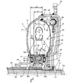
本発明の第1の実施の形態について図1〜図3を参照しながら説明すると、先ず図1において、このトルクコンバータは、ポンプインペラ5と、このポンプインペラ5に対向して配置されるタービンランナ6と、前記ポンプインペラ5および前記タービンランナ6の内周部間に配置されるステータ7とを備え、前記ポンプインペラ5、前記タービンランナ6および前記ステータ7間には、矢印8で示すように作動オイルを循環させる循環回路9が形成される。
A first embodiment of the present invention will be described with reference to FIGS. 1 to 3. First, in FIG. 1, the torque converter includes a
前記ポンプインペラ5は、椀状のポンプシェル10およびリング状のポンプコア12が、前記ポンプシェル10および前記ポンプコア12の周方向に沿って配列される複数枚のポンプブレード11で連結されて成る。
The
前記タービンランナ6は、椀状のタービンシェル13に、リング状のタービンコア15が、前記タービンシェル13および前記タービンコア15の周方向に沿って配列される複数枚のタービンブレード14で連結されて成る。
In the
前記ポンプシェル10の内周部にはポンプハブ16が溶接によって固設され、このポンプハブ16には、トルクコンバータに作動オイルを供給するオイルポンプ(図示せず)が連動、連結される。また前記ポンプハブ16との間に軸方向の間隔をあけた位置に配置されるタービンハブ17が前記タービンシェル13の内周部に固定される。
A
また前記ポンプシェル10の外周部には、前記タービンランナ6を外側から覆う伝動カバー18が溶接によって結合されており、この伝動カバー18の外周部にリングギヤ19が溶接によって固定される。前記リングギヤ19には、駆動源であるエンジンのクランクシャフトに連なる駆動板(図示せず)が締結され、前記ポンプインペラ5には、前記エンジンから回転動力が入力される。
A
前記タービンハブ17には出力シャフト20がスプライン結合され、前記伝動カバー18がその中心部に一体に有する有底円筒状の支持筒部18aに、前記出力シャフト20の端部が軸受ブッシュ21を介して支持される。また前記タービンハブ17および前記サイドカバー18間には第1のスラストベアリング22が介装される。
An
前記伝動カバー18および前記タービンシェル13間には、前記タービンランナ6および前記伝動カバー18間を直結し得るロックアップクラッチ24が収容される。このロックアップクラッチ24は、前記伝動カバー18に摩擦接続可能なクラッチピストン25を有するとともに該クラッチピストン25を前記伝動カバー18に摩擦接続させた接続状態ならびに摩擦接続を解除した非接続状態を切替えることが可能である。
Between the
前記クラッチピストン25と、前記タービンシェル13との間にはダンパ機構26が設けられる。このダンパ機構26は、前記クラッチピストン25の周方向に間隔をあけた複数箇所に保持されるダンパスプリング27と、それらのダンパスプリング27の一端部に当接するようにして前記クラッチピストン25に固定される複数のリテーナ28と、前記ダンパスプリング27を前記リテーナ28との間に挟むようにして前記タービンシェル13に溶接される複数のスプリング挟み腕29とを備える。
A
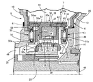
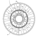
図2および図3を併せて参照して、前記ステータ7は、前記ポンプハブ16および前記タービンハブ17間に配置されるステータハブ30に、リング状のステータコア32が複数のステータブレード31で連結されて成る。
Referring to FIGS. 2 and 3 together, the
前記スタータハブ30は、円筒部30aと、該円筒部30aの軸方向中間部から半径方向内方に張り出す内向き張り出し部30bと、前記円筒部30aで同軸に囲繞されるようにして前記内向き張り出し部30bの内端部から前記ポンプハブ16側に突出する内側円筒部30cとを一体に有するように形成される。
The
前記ステータハブ30と、前記タービンハブ17とともに回転する前記出力シャフト20を相対回転自在に囲繞するステータシャフト35との間には、一方向クラッチ36が介設される。この一方向クラッチ36は、前記ステータハブ30の前記円筒部30aに前記タービンハブ17側から圧入されるアウターレース37と、インナーレース38との間にクラッチ部材39が設けられて成る。
A one-
前記ステータハブ30における前記円筒部30aのうち前記内向き張り出し部30bよりも前記ポンプハブ16側の内周には、その周方向に等間隔をあけた複数箇所たとえば4箇所に配置されて円弧状に凹んだ第1の係止凹部41が形成され、前記円筒部30aのうち前記内向き張り出し部30bよりも前記タービンハブ17側の内周には、その周方向に等間隔をあけた複数箇所たとえば4箇所に配置されて円弧状に凹んだ第2の係止凹部42が形成される。
Of the
前記内向き張り出し部30bには、前記第2の係止部42に係合する係合突起43aを外周に有するリング状の押さえ部材43が、前記一方向クラッチ36を前記内向き張り出し部30bとの間に保持するようにして前記タービンハブ17側から装着されており、この押さえ部材43の内周部には、前記ステータハブ30の前記円筒部30aで同軸に囲繞される内側円筒部43bが前記タービンハブ17側に突出するようにして一体に形成される。
The inwardly projecting
前記一方向クラッチ36の前記インナーレース38は、前記ステータシャフト35にスプライン結合されており、このステータシャフト35は、ミッションケース(図示せず)に回転不能に支持される。
The
ところで前記ロックアップクラッチ24のクラッチピストン25およびタービンランナ6間には第1液室44が形成され、前記クラッチピストン25および前記伝動カバー18間には第2液室45が形成される。第1液室44は前記ポンプインペラ5および前記タービンランナ6間を介して前記循環回路9に連通しており、この循環回路9は、前記ポンプハブ16および前記ステータシャフト35間に形成される環状の第1の通路46に連通する。また第2液室45は、前記出力シャフト20に設けられる通路孔47を介して前記出力シャフト20の中心の第2の通路48に連通する。第1および第2の通路46,48には、図示しないオイルポンプからの作動液が択一的に切替えて供給される。
Meanwhile, a first
前記ポンプハブ16および前記ステータハブ30間には第2のスラストベアリング50が介装され、前記タービンハブ17および前記ステータハブ30間には第3のスラストベアリング51が介装される。
A second thrust bearing 50 is interposed between the
第2のスラストベアリング50における背面プレート50aの内周部は、前記ステータハブ30における内側円筒部30cに当接、支持され、この背面プレート50aの外周の複数箇所に突設される係合突起50aaは、前記円筒部30aのうち前記内向き張り出し部30bよりも前記ポンプハブ16側の内周に形成される第1の係止凹部41に係合される。また第3のスラストベアリング51における背面プレート51aの内周部は前記押さえ部材43の内側円筒部43bに当接、支持され、この背面プレート51aの外周の複数箇所に突設される係合突起51aaは、前記円筒部30aのうち前記内向き張り出し部30bよりも前記タービンハブ16側の内周に形成される第2の係止凹部42に係合される。
The inner peripheral portion of the
ところで前記伝動カバー18および前記ポンプシェル10は、軸方向に相互に突き当てられた状態で溶接によって結合されるものであり、前記ポンプシェル10の外周部には、前記伝動カバー18の外周部先端を突き当てる環状段部10aが形成される。
By the way, the
一方、前記ポンプハブ16および前記ステータハブ30間、ならびに前記タービンハブ17および前記ステータハブ30間のいずれかに、軸方向寸法調整用のシム53が介装されるものであり、この第1の実施の形態では、前記ポンプハブ16および前記ステータハブ30間に介装される第2のスラストベアリング50と、前記ステータハブ30との間に前記シム53が挟まれる。
On the other hand, a
前記ポンプインペラ5、前記タービンランナ6および前記ステータ7間に形成される前記循環回路9を第1の通路46に通じさせるための第3の通路54が、前記ステータハブ30における前記内向き張り出し部30bおよび前記シム53間に形成されるものであり、その第3の通路54を形成するための通路溝55が、前記内向き張り出し部30bの前記シム53側に臨む面に十字状に形成され、その第3の通路54からの作動液を前記一方向クラッチ36側に導く導孔56が一端を前記通路溝55に開口させて前記内向き張り出し部30bに設けられる。
A third passage 54 for connecting the
しかも前記シム53の外周の前記通路溝55に個別に対応した4箇所には、前記循環回路9を前記第3の通路54に通じさせる切欠き57が設けられ、前記第2のスラストベアリング50の背面プレート50aの外周にも前記切欠き57に対応した切欠き58が設けられる。
In addition,
また前記シム53の外周の複数箇所には係合突起53aが突設されており、それらの係合突起53aは、前記ステータハブ30における前記円筒部30aのうち前記内向き張り出し部30bよりも前記ポンプハブ16側の内周に形成される第1の係止凹部41に係合される。
Engaging
さらに前記押さえ部材43には、前記循環回路9を第1の通路46に通じさせるための第4の通路59を、前記第3のスラストベアリング51の背面プレート51aとの間に形成するための十字状の通路溝60が形成され、この第4の通路59からの作動液を前記一方向クラッチ36側に導く導孔61が前記押さえ部材43に設けられる。
Further, the holding
次にこの第1の実施の形態の作用について説明すると、伝動カバー18およびポンプシェル10が、ポンプシェル10の環状段部10aに伝動カバー18を突き当てるようにして軸方向に相互に突き当てられた状態で溶接によって結合されるので、トルクコンバータ全体の軸方向寸法のばらつきを抑えることが可能である。しかもポンプハブ16およびステータハブ30間、ならびにタービンハブ17およびステータハブ30間のいずれかに、軸方向寸法調整用のシム53が介装されるので、内部部品の寸法のばらつきに伴うクリアランスの調整を容易とし、内部部品の寸法を厳しく管理することを不要とし、切削および研磨等の加工や、特別な寸法管理を不要としてコストの低減を図ることができる。
Next, the operation of the first embodiment will be described. The
またポンプハブ16およびステータハブ30間に介装される第2のスラストベアリング50と、前記ステータハブ30との間にシム53が挟まれるので、伝動カバー18側からタービンランナ6、ステータ7およびポンプインペラ5が順に組み付けられる際に、ポンプインペラ5を組付ける前の状態で適切な厚みのシム53を選択して組付けることができ、トルクコンバータの組立て性を損なうことなくシム53を装着することができる。
Further, since the
すなわち伝動カバー18、タービンランナ6およびステータ7を順次組み付けた状態で、図1で示すように、伝動カバー18の外周部先端ならびに前記ステータハブ30における前記内向き張り出し部30bの前記ポンプハブ16側の面との間の距離L1と、組み付け前の前記ポンプインペラ5におけるポンプシェル10の環状段10aおよびポンプハブ16の前記ステータハブ30側に臨む面間の距離L2とをそれぞれ測定し、(L2−L1)を演算することで、前記内向き張り出し部30bの前記ポンプハブ16側の面と、ポンプハブ16の前記ステータハブ30側に臨む面との間の距離を得ることができ、その結果、必要な厚みのシム53を選択することができる。次いで厚みを選択したシム53および第2のスラストベアリング50をステータハブ30に当接させた状態で、伝動カバー18の外周部先端から前記第2のスラストベアリング50の前記ポンプハブ16側の面までの寸法を測定、確認した後に、ポンプランナ5の環状段部10aに伝動カバー18を突き当てて結合することでトルクコンバータの組み付けが完了することになる。
That is, with the
またポンプインペラ5、タービンランナ6およびステータ7間に形成される循環回路9を、ステータハブ30および前記シム53間に形成される第3の通路54に通じさせる切欠き57が前記シム53の外周に形成されるので、シム53が設置されても作動液の流通路を確保することができる。
Further, a
さらにシム53の外周に、前記ステータハブ30に形成される第1の係止凹部41に係合する係合突起53aが突設されるので、ステータハブ30およびシム53の相対回転が生じないようにして、シム53およびステータハブ30間の第3の通路54と、循環回路9との間が塞がることを防止することができる。
Further, since an engaging
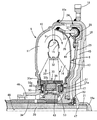
次に本発明の第2の実施の形態について図4を参照しながら説明するが、上記第1の実施の形態に対応する部分には同一の参照符号を付して図示するのみとし、詳細な説明については省略する。 Next, a second embodiment of the present invention will be described with reference to FIG. 4. The parts corresponding to those of the first embodiment are only given the same reference numerals and are shown in detail. The explanation is omitted.
この第2の実施の形態では、前記タービンハブ17および前記ステータハブ30間に介装される第3のスラストベアリング51と、前記ステータハブ30との間に前記シム53が挟まれる。
In the second embodiment, the
前記ステータハブ30における内向き張り出し部30bおよび前記シム53間には、前記循環回路9を第1の通路46に通じさせるための第4の通路59が形成されるものであり、その第4の通路59には前記循環回路9が前記シム53の外周の切欠き57を介して連通され、前記シム53の外周の複数箇所に突設される係合突起53aは、前記ステータハブ30における前記円筒部30aのうち前記内向き張り出し部30bよりも前記タービンハブ17側の内周に形成される第2の係止凹部42に係合される。
A
この第2の実施の形態によってもトルクコンバータ全体の軸方向寸法のばらつきを抑えつつ、内部部品の寸法のばらつきに伴うクリアランス調整を容易としてコスト低減を図ることができる。 According to the second embodiment, the variation in the axial direction of the entire torque converter can be suppressed, and the clearance adjustment associated with the variation in the dimensions of the internal components can be easily performed to reduce the cost.
以上、本発明の実施の形態について説明したが、本発明は上記実施の形態に限定されるものではなく、特許請求の範囲に記載された本発明を逸脱することなく種々の設計変更を行うことが可能である。 Although the embodiments of the present invention have been described above, the present invention is not limited to the above-described embodiments, and various design changes can be made without departing from the present invention described in the claims. Is possible.
5・・・ポンプインペラ
6・・・タービンランナ
7・・・ステータ
9・・・循環回路
10・・・ポンプシェル
11・・・ポンプブレード
12・・・ポンプコア
13・・・タービンシェル
14・・・タービンブレード
15・・・タービンコア
16・・・ポンプハブ
17・・・タービンハブ
18・・・伝動カバー
30・・・ステータハブ
31・・・ステータブレード
32・・・ステータコア
41,42・・・係止凹部
50・・・スラストベアリング
53・・・シム
53a・・・係合突起
54・・・通路
57・・・切欠き
DESCRIPTION OF
Claims (4)
Priority Applications (1)
| Application Number | Priority Date | Filing Date | Title |
|---|---|---|---|
| JP2016081451A JP6625474B2 (en) | 2016-04-14 | 2016-04-14 | Torque converter |
Applications Claiming Priority (1)
| Application Number | Priority Date | Filing Date | Title |
|---|---|---|---|
| JP2016081451A JP6625474B2 (en) | 2016-04-14 | 2016-04-14 | Torque converter |
Publications (2)
| Publication Number | Publication Date |
|---|---|
| JP2017190841A true JP2017190841A (en) | 2017-10-19 |
| JP6625474B2 JP6625474B2 (en) | 2019-12-25 |
Family
ID=60085814
Family Applications (1)
| Application Number | Title | Priority Date | Filing Date |
|---|---|---|---|
| JP2016081451A Expired - Fee Related JP6625474B2 (en) | 2016-04-14 | 2016-04-14 | Torque converter |
Country Status (1)
| Country | Link |
|---|---|
| JP (1) | JP6625474B2 (en) |
-
2016
- 2016-04-14 JP JP2016081451A patent/JP6625474B2/en not_active Expired - Fee Related
Also Published As
| Publication number | Publication date |
|---|---|
| JP6625474B2 (en) | 2019-12-25 |
Similar Documents
| Publication | Publication Date | Title |
|---|---|---|
| US9303747B2 (en) | Lock-up device for torque converter | |
| US9267555B2 (en) | Lock-up device for torque converter | |
| JP5401821B2 (en) | Starting device | |
| US8967349B2 (en) | Lock-up device for torque converter | |
| US9200685B2 (en) | Lock-up device for torque converter | |
| US10683908B2 (en) | Torque converter | |
| US10955037B2 (en) | Torque converter | |
| CN120239658A (en) | Rotor hub and hybrid drive module having the same | |
| KR20140110867A (en) | Torque converter | |
| JP4483036B2 (en) | Torque converter | |
| US6793052B2 (en) | Torque converter | |
| JP2015232372A (en) | Torque converter | |
| JP6173814B2 (en) | clutch | |
| JP2017190841A (en) | Torque converter | |
| US8042666B2 (en) | Hydrodynamic clutch device | |
| US10260609B2 (en) | Fluid transmission device | |
| WO2017170396A1 (en) | Drive transmission device for vehicle | |
| JP2007100716A (en) | Drive sprocket support structure | |
| JP5986868B2 (en) | clutch | |
| JP2014074439A (en) | Starting device | |
| US20010050204A1 (en) | Hydrodynamic clutch device | |
| JP2006170345A (en) | Torque converter | |
| JP2012211707A (en) | Lockup clutch of fluid coupling device | |
| JP2007032636A (en) | Automatic transmission drum clutch | |
| JP5051057B2 (en) | Fluid transmission device |
Legal Events
| Date | Code | Title | Description |
|---|---|---|---|
| A621 | Written request for application examination |
Free format text: JAPANESE INTERMEDIATE CODE: A621 Effective date: 20180911 |
|
| A977 | Report on retrieval |
Free format text: JAPANESE INTERMEDIATE CODE: A971007 Effective date: 20190703 |
|
| A131 | Notification of reasons for refusal |
Free format text: JAPANESE INTERMEDIATE CODE: A131 Effective date: 20190710 |
|
| A521 | Request for written amendment filed |
Free format text: JAPANESE INTERMEDIATE CODE: A523 Effective date: 20190903 |
|
| TRDD | Decision of grant or rejection written | ||
| A01 | Written decision to grant a patent or to grant a registration (utility model) |
Free format text: JAPANESE INTERMEDIATE CODE: A01 Effective date: 20191106 |
|
| A61 | First payment of annual fees (during grant procedure) |
Free format text: JAPANESE INTERMEDIATE CODE: A61 Effective date: 20191127 |
|
| R150 | Certificate of patent or registration of utility model |
Ref document number: 6625474 Country of ref document: JP Free format text: JAPANESE INTERMEDIATE CODE: R150 |
|
| R250 | Receipt of annual fees |
Free format text: JAPANESE INTERMEDIATE CODE: R250 |
|
| R250 | Receipt of annual fees |
Free format text: JAPANESE INTERMEDIATE CODE: R250 |
|
| LAPS | Cancellation because of no payment of annual fees |