JP2017190835A - Bearing device and sealing device - Google Patents
Bearing device and sealing device Download PDFInfo
- Publication number
- JP2017190835A JP2017190835A JP2016080952A JP2016080952A JP2017190835A JP 2017190835 A JP2017190835 A JP 2017190835A JP 2016080952 A JP2016080952 A JP 2016080952A JP 2016080952 A JP2016080952 A JP 2016080952A JP 2017190835 A JP2017190835 A JP 2017190835A
- Authority
- JP
- Japan
- Prior art keywords
- roll
- inner ring
- packing
- groove
- main body
- Prior art date
- Legal status (The legal status is an assumption and is not a legal conclusion. Google has not performed a legal analysis and makes no representation as to the accuracy of the status listed.)
- Granted
Links
Images

Classifications
-
- F—MECHANICAL ENGINEERING; LIGHTING; HEATING; WEAPONS; BLASTING
- F16—ENGINEERING ELEMENTS AND UNITS; GENERAL MEASURES FOR PRODUCING AND MAINTAINING EFFECTIVE FUNCTIONING OF MACHINES OR INSTALLATIONS; THERMAL INSULATION IN GENERAL
- F16C—SHAFTS; FLEXIBLE SHAFTS; ELEMENTS OR CRANKSHAFT MECHANISMS; ROTARY BODIES OTHER THAN GEARING ELEMENTS; BEARINGS
- F16C19/00—Bearings with rolling contact, for exclusively rotary movement
- F16C19/22—Bearings with rolling contact, for exclusively rotary movement with bearing rollers essentially of the same size in one or more circular rows, e.g. needle bearings
- F16C19/24—Bearings with rolling contact, for exclusively rotary movement with bearing rollers essentially of the same size in one or more circular rows, e.g. needle bearings for radial load mainly
- F16C19/26—Bearings with rolling contact, for exclusively rotary movement with bearing rollers essentially of the same size in one or more circular rows, e.g. needle bearings for radial load mainly with a single row of rollers
-
- F—MECHANICAL ENGINEERING; LIGHTING; HEATING; WEAPONS; BLASTING
- F16—ENGINEERING ELEMENTS AND UNITS; GENERAL MEASURES FOR PRODUCING AND MAINTAINING EFFECTIVE FUNCTIONING OF MACHINES OR INSTALLATIONS; THERMAL INSULATION IN GENERAL
- F16C—SHAFTS; FLEXIBLE SHAFTS; ELEMENTS OR CRANKSHAFT MECHANISMS; ROTARY BODIES OTHER THAN GEARING ELEMENTS; BEARINGS
- F16C33/00—Parts of bearings; Special methods for making bearings or parts thereof
- F16C33/72—Sealings
- F16C33/76—Sealings of ball or roller bearings
- F16C33/78—Sealings of ball or roller bearings with a diaphragm, disc, or ring, with or without resilient members
- F16C33/7803—Sealings of ball or roller bearings with a diaphragm, disc, or ring, with or without resilient members suited for particular types of rolling bearings
- F16C33/7809—Sealings of ball or roller bearings with a diaphragm, disc, or ring, with or without resilient members suited for particular types of rolling bearings for needle roller bearings
-
- B—PERFORMING OPERATIONS; TRANSPORTING
- B22—CASTING; POWDER METALLURGY
- B22D—CASTING OF METALS; CASTING OF OTHER SUBSTANCES BY THE SAME PROCESSES OR DEVICES
- B22D11/00—Continuous casting of metals, i.e. casting in indefinite lengths
- B22D11/12—Accessories for subsequent treating or working cast stock in situ
- B22D11/128—Accessories for subsequent treating or working cast stock in situ for removing
- B22D11/1287—Rolls; Lubricating, cooling or heating rolls while in use
-
- F—MECHANICAL ENGINEERING; LIGHTING; HEATING; WEAPONS; BLASTING
- F16—ENGINEERING ELEMENTS AND UNITS; GENERAL MEASURES FOR PRODUCING AND MAINTAINING EFFECTIVE FUNCTIONING OF MACHINES OR INSTALLATIONS; THERMAL INSULATION IN GENERAL
- F16C—SHAFTS; FLEXIBLE SHAFTS; ELEMENTS OR CRANKSHAFT MECHANISMS; ROTARY BODIES OTHER THAN GEARING ELEMENTS; BEARINGS
- F16C13/00—Rolls, drums, discs, or the like; Bearings or mountings therefor
- F16C13/02—Bearings
-
- F—MECHANICAL ENGINEERING; LIGHTING; HEATING; WEAPONS; BLASTING
- F16—ENGINEERING ELEMENTS AND UNITS; GENERAL MEASURES FOR PRODUCING AND MAINTAINING EFFECTIVE FUNCTIONING OF MACHINES OR INSTALLATIONS; THERMAL INSULATION IN GENERAL
- F16C—SHAFTS; FLEXIBLE SHAFTS; ELEMENTS OR CRANKSHAFT MECHANISMS; ROTARY BODIES OTHER THAN GEARING ELEMENTS; BEARINGS
- F16C33/00—Parts of bearings; Special methods for making bearings or parts thereof
- F16C33/72—Sealings
- F16C33/76—Sealings of ball or roller bearings
- F16C33/78—Sealings of ball or roller bearings with a diaphragm, disc, or ring, with or without resilient members
- F16C33/7816—Details of the sealing or parts thereof, e.g. geometry, material
- F16C33/782—Details of the sealing or parts thereof, e.g. geometry, material of the sealing region
- F16C33/7826—Details of the sealing or parts thereof, e.g. geometry, material of the sealing region of the opposing surface cooperating with the seal, e.g. a shoulder surface of a bearing ring
-
- F—MECHANICAL ENGINEERING; LIGHTING; HEATING; WEAPONS; BLASTING
- F16—ENGINEERING ELEMENTS AND UNITS; GENERAL MEASURES FOR PRODUCING AND MAINTAINING EFFECTIVE FUNCTIONING OF MACHINES OR INSTALLATIONS; THERMAL INSULATION IN GENERAL
- F16C—SHAFTS; FLEXIBLE SHAFTS; ELEMENTS OR CRANKSHAFT MECHANISMS; ROTARY BODIES OTHER THAN GEARING ELEMENTS; BEARINGS
- F16C33/00—Parts of bearings; Special methods for making bearings or parts thereof
- F16C33/72—Sealings
- F16C33/76—Sealings of ball or roller bearings
- F16C33/78—Sealings of ball or roller bearings with a diaphragm, disc, or ring, with or without resilient members
- F16C33/7816—Details of the sealing or parts thereof, e.g. geometry, material
- F16C33/783—Details of the sealing or parts thereof, e.g. geometry, material of the mounting region
-
- F—MECHANICAL ENGINEERING; LIGHTING; HEATING; WEAPONS; BLASTING
- F16—ENGINEERING ELEMENTS AND UNITS; GENERAL MEASURES FOR PRODUCING AND MAINTAINING EFFECTIVE FUNCTIONING OF MACHINES OR INSTALLATIONS; THERMAL INSULATION IN GENERAL
- F16C—SHAFTS; FLEXIBLE SHAFTS; ELEMENTS OR CRANKSHAFT MECHANISMS; ROTARY BODIES OTHER THAN GEARING ELEMENTS; BEARINGS
- F16C33/00—Parts of bearings; Special methods for making bearings or parts thereof
- F16C33/72—Sealings
- F16C33/76—Sealings of ball or roller bearings
- F16C33/80—Labyrinth sealings
-
- F—MECHANICAL ENGINEERING; LIGHTING; HEATING; WEAPONS; BLASTING
- F16—ENGINEERING ELEMENTS AND UNITS; GENERAL MEASURES FOR PRODUCING AND MAINTAINING EFFECTIVE FUNCTIONING OF MACHINES OR INSTALLATIONS; THERMAL INSULATION IN GENERAL
- F16C—SHAFTS; FLEXIBLE SHAFTS; ELEMENTS OR CRANKSHAFT MECHANISMS; ROTARY BODIES OTHER THAN GEARING ELEMENTS; BEARINGS
- F16C2322/00—Apparatus used in shaping articles
Landscapes
- Engineering & Computer Science (AREA)
- General Engineering & Computer Science (AREA)
- Mechanical Engineering (AREA)
- Sealing Using Fluids, Sealing Without Contact, And Removal Of Oil (AREA)
- Sealing Of Bearings (AREA)
- Rolling Contact Bearings (AREA)
- Gasket Seals (AREA)
Abstract
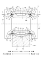
【課題】軸受装置の内輪と、回転可能に支持するロールとの間の隙間に水が滞留しないようにして腐食の発生を防ぐ。【解決手段】軸受装置7は、杵型ロール3の小径軸部4に外嵌する内輪11、筒状の外輪部材12、円筒ころ13及び軸箱14を有する軸受本体10と、外部からの水の浸入を防止するための密封構造体30とを備えている。密封構造体30は、ロール3の大径部5に形成されている凹周溝6に一部が入ってラビリンス隙間を形成するためのラビリンスリング31と、内輪11の軸方向側部16に取り付けられロール3の一部に接触し内輪11とロール3との間に外部から水が浸入するのを防止するためのパッキン51とを有している。【選択図】 図1[PROBLEMS] To prevent the occurrence of corrosion by preventing water from staying in a gap between an inner ring of a bearing device and a roll that is rotatably supported. A bearing device includes a bearing body having an inner ring, a cylindrical outer ring member, a cylindrical roller, and a shaft box that are externally fitted to a small-diameter shaft portion of a saddle type roll, and water from the outside. And a sealing structure 30 for preventing the intrusion. The sealing structure 30 is attached to a labyrinth ring 31 for forming a labyrinth gap by partially entering the concave circumferential groove 6 formed in the large diameter portion 5 of the roll 3, and to the axial side portion 16 of the inner ring 11. And a packing 51 for preventing water from entering between the inner ring 11 and the roll 3 and coming into contact with a part of the roll 3. [Selection] Figure 1
Description
本発明は、杵型ロールを回転可能として支持する軸受装置、及び、この軸受装置に設けられる密封装置に関する。 The present invention relates to a bearing device that supports a saddle type roll so as to be rotatable, and a sealing device provided in the bearing device.
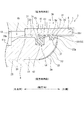
製鋼工程に用いられる連続鋳造機の駆動ロールでは、重荷重による杵型ロールのたわみを抑えるため、図11に示すように、ロール90の中央の小径軸部91を軸受装置99によって支持する構成が採用されている。この構成を得るために、軸受装置99に含まれる内輪95、外輪部材94及び軸箱93等は二分割構造を有している。
In the drive roll of the continuous casting machine used in the steel making process, in order to suppress the deflection of the saddle type roll due to heavy load, as shown in FIG. 11, a configuration in which the small-
連続鋳造機に用いられる軸受装置99には冷却水が降りかかることから、軸受装置99とロール90の大径部92との間から軸受内部等に冷却水が浸入するのを防止するために、軸受装置99には、ラビリンスリング98や、オイルシール97が設けられている(特許文献1参照)。図11に示す軸受装置99は、更に、オイルシール97と並んでパッキン96も設けられている。
Since the cooling water falls on the
図12は、図11に示す軸受装置99の右側の一部を示す断面図である。ラビリンスリング98は、その一部がロール90の大径部92に形成されている凹周溝92aに入った状態となることにより凹周溝92aとの間にラビリンス隙間を形成し、外部から冷却水等の異物がロール90のネック部90aと内輪95との間(隙間100)に浸入するのを抑制している。一方で、ラビリンスリング98、オイルシール97及びパッキン96は、外部から冷却水等の異物が、内輪95と外輪部材94との間(軸受内部)へ浸入するのを防止している。
12 is a cross-sectional view showing a part of the right side of the
ロール90(図11参照)は、軸箱93と共に固定状態にあるラビリンスリング98に対して回転することから、図12に示すように、ラビリンスリング98とロール90(凹周溝92a)との間には隙間が設けられており、冷却水の浸入を抑制することは可能であるが、浸入を完全に防ぐことはできない。
Since the roll 90 (refer to FIG. 11) rotates with respect to the
このため、冷却水が、ロール90のネック部90aと内輪95の軸方向側部95aとの間の隙間100に浸入し、浸入した冷却水が隙間100に滞留することがあり、腐食の発生原因となってしまう。このまま使用を継続すると、この腐食部分が起点となって例えばロール90を損傷させる可能性がある。
For this reason, the cooling water may enter the
そこで、本発明は、内輪とロールとの間の隙間に水が滞留しないようにして腐食の発生を防ぐことを可能とする軸受装置、及び、前記腐食の発生を防ぐための密封装置を提供することを目的とする。 Therefore, the present invention provides a bearing device capable of preventing the occurrence of corrosion by preventing water from staying in the gap between the inner ring and the roll, and a sealing device for preventing the occurrence of the corrosion. For the purpose.
(1)本発明は、小径軸部と大径部とを有する杵型ロールの当該小径軸部に外嵌する内輪、前記内輪の径方向外側に設けられている筒状の外輪部材、前記内輪と前記外輪部材との間に設けられている複数の転動体、及び、前記外輪部材を支持している軸箱を有する軸受本体と、前記転動体が設けられている軸受内部、及び、前記内輪と前記ロールとの間に、外部から水が浸入するのを防止するための密封構造体と、を備えた軸受装置であって、前記密封構造体は、前記内輪の径方向外側において前記軸受本体に取り付けられ前記ロールの大径部に形成されている凹周溝に一部が入って当該凹周溝との間でラビリンス隙間を形成するラビリンスリングと、前記内輪の軸方向側部に取り付けられ前記ロールの一部に接触し当該内輪と当該ロールとの間に外部から水が浸入するのを防止するためのパッキンと、を有している。 (1) The present invention provides an inner ring that fits externally on the small-diameter shaft portion of a saddle type roll having a small-diameter shaft portion and a large-diameter portion, a cylindrical outer ring member that is provided on the radially outer side of the inner ring, and the inner ring And a plurality of rolling elements provided between the outer ring member, a bearing body having a shaft box supporting the outer ring member, a bearing interior in which the rolling element is provided, and the inner ring And a sealing structure for preventing water from entering from the outside between the roll and the roll, wherein the sealing structure is formed on the bearing main body at a radially outer side of the inner ring. A labyrinth ring that is partly inserted into a concave groove formed in the large-diameter portion of the roll and forms a labyrinth gap with the concave groove, and is attached to an axial side portion of the inner ring. The inner ring and the roll in contact with a part of the roll Water from the outside has a packing for preventing the intrusion between.
この軸受装置によれば、内輪の軸方向側部に取り付けられているパッキンが、ロールの一部に接触して内輪とロールとの間に外部から水が浸入するのを防止することで、これら内輪とロールとの間の隙間に水が滞留しないようにして腐食の発生を防ぐことが可能となる。 According to this bearing device, the packing attached to the axial side portion of the inner ring makes contact with a part of the roll and prevents water from entering from the outside between the inner ring and the roll. It is possible to prevent the occurrence of corrosion by preventing water from staying in the gap between the inner ring and the roll.
(2)また、前記(1)に記載の軸受装置において、前記内輪は、前記軸方向側部において、径方向外側から、当該内輪の中心線に直交する仮想面上に位置する円環面と、軸方向中央に向かうにしたがって縮径する円弧状面と、前記小径軸部に嵌合している円筒面と、を有し、前記内輪の前記軸方向側部のうちの少なくとも前記円弧状面に環状の取り付け溝が設けられており、前記パッキンは、前記取り付け溝に取り付けられている本体部と、当該本体部から前記ロール側に設けられ当該ロールに接触可能である接触部と、を有している構成とすることができる。
この構成によれば、内輪の円弧状面にパッキンが取り付けられた構成となり、ロールのネック部との間で止水する構成となる。また、円環面を、内輪の加工の際に活用することができる。
(2) Further, in the bearing device according to (1), the inner ring includes an annular surface located on a virtual plane perpendicular to the center line of the inner ring from the radially outer side at the axial side portion. And an arcuate surface that decreases in diameter toward the center in the axial direction, and a cylindrical surface that is fitted to the small-diameter shaft portion, and at least the arcuate surface of the axial side portion of the inner ring An annular mounting groove is provided, and the packing includes a main body part attached to the mounting groove, and a contact part provided on the roll side from the main body part and capable of contacting the roll. It can be set as the structure which is carrying out.
According to this structure, it becomes the structure by which packing was attached to the circular arc-shaped surface of an inner ring | wheel, and it becomes the structure which stops water between the neck parts of a roll. In addition, the annular surface can be utilized when processing the inner ring.
(3)また、前記(1)に記載の軸受装置において、前記内輪は、前記軸方向側部において、径方向外側から、環状の取り付け溝と、軸方向中央に向かうにしたがって縮径する円弧状面と、前記小径軸部に嵌合している円筒面と、を有し、前記パッキンは、前記取り付け溝に取り付けられている本体部と、当該本体部から前記ラビリンスリング側に設けられ当該ラビリンスリングの内周面に滑り接触可能である第一接触部と、前記本体部から前記ロール側に設けられ当該ロールに接触可能である第二接触部と、を有している構成とすることができる。
この構成によれば、パッキンは、内輪とロールとの間に外部から水が浸入するのを防止する機能の他に、ラビリンスリングと内輪との間から水が浸入するのを防止する機能も有することができる。つまり、一つのパッキンで二つの止水機能を有することができる。
(3) Further, in the bearing device according to (1), the inner ring has an arcuate shape whose diameter decreases from the radially outer side toward the annular mounting groove and toward the axial center at the axial side portion. And a cylindrical surface fitted to the small-diameter shaft portion, and the packing is provided on the labyrinth ring side from the main body portion, the main body portion being attached to the attachment groove, and the labyrinth It is set as the structure which has the 1st contact part which can be slidably contacted to the internal peripheral surface of a ring, and the 2nd contact part which is provided in the said roll side from the said main-body part and can contact the said roll. it can.
According to this configuration, the packing has a function of preventing water from entering between the labyrinth ring and the inner ring, in addition to the function of preventing water from entering from the outside between the inner ring and the roll. be able to. That is, one packing can have two water stop functions.
また、前記(3)に記載の軸受装置において、前記取り付け溝は、径方向外側に臨む円筒面と、軸方向外側に臨む円環面とからなり、前記パッキンは、断面四角形であり、当該パッキンの外周部が前記第一接触部であり、当該パッキンの軸方向側部が前記第二接触部である構成とすることができる。この場合、パッキンの形状が簡単であり、密封構造体の簡素化が可能となる。
または、前記(3)に記載の軸受装置において、前記取り付け溝は、軸方向外側の第一溝部と、当該第一溝部の隣りに設けられ当該第一溝部よりも溝底の直径が小さい第二溝部とを有し、前記パッキンは、前記第一溝部及び前記第二溝部に嵌まる前記本体部と、当該本体部から径方向外側に延びて設けられている前記第一接触部と、前記本体部から軸方向外側に延びて設けられている前記第二接触部と、を有している構成とすることができる。この構成の場合、パッキンは第一溝及び第二溝に嵌まることで、安定した取り付け状態が得られる。
In the bearing device according to (3), the mounting groove includes a cylindrical surface facing radially outward and an annular surface facing axially outer, and the packing has a quadrangular cross section. The outer peripheral portion of the packing may be the first contact portion, and the axial side portion of the packing may be the second contact portion. In this case, the shape of the packing is simple, and the sealing structure can be simplified.
Alternatively, in the bearing device according to (3), the mounting groove includes a first groove portion on the outer side in the axial direction and a second groove that is provided adjacent to the first groove portion and has a smaller groove bottom diameter than the first groove portion. The packing includes the main body portion that fits into the first groove portion and the second groove portion, the first contact portion that extends radially outward from the main body portion, and the main body. And the second contact portion provided to extend outward in the axial direction from the portion. In the case of this configuration, the packing is fitted in the first groove and the second groove, so that a stable attachment state is obtained.
また、前記(1)に記載の軸受装置において、前記内輪は、前記軸方向側部において、径方向外側から、環状の取り付け溝と、当該内輪の中心線に直交する仮想面上に位置する円環面と、軸方向中央に向かうにしたがって縮径する円弧状面と、前記小径軸部に嵌合している円筒面と、を有し、前記パッキンは、前記取り付け溝に取り付けられていると共に前記円環面を覆っている本体部と、当該本体部から前記ラビリンスリング側に設けられ当該ラビリンスリングの内周面に滑り接触可能である第一接触部と、前記本体部から前記ロール側に設けられ当該ロールに接触可能である第二接触部と、を有している構成とすることができる。
この構成の場合、パッキンは、内輪とロールとの間に外部から水が浸入するのを防止する機能の他に、ラビリンスリングと内輪との間から水が浸入するのを防止する機能も有することができる。つまり、一つのパッキンで二つの止水機能を有することができる。また、円環面を、内輪の加工の際に活用することができる。
Further, in the bearing device according to (1), the inner ring has a circular mounting groove and a circle positioned on a virtual plane orthogonal to the center line of the inner ring from the radially outer side in the axial side portion. An annular surface, an arcuate surface that decreases in diameter toward the center in the axial direction, and a cylindrical surface that is fitted to the small-diameter shaft portion, and the packing is attached to the attachment groove A main body portion covering the annular surface, a first contact portion provided on the labyrinth ring side from the main body portion and capable of sliding contact with an inner peripheral surface of the labyrinth ring, and from the main body portion to the roll side. A second contact portion that is provided and can contact the roll.
In this configuration, the packing has a function of preventing water from entering between the inner ring and the roll, as well as a function of preventing water from entering between the labyrinth ring and the inner ring. Can do. That is, one packing can have two water stop functions. In addition, the annular surface can be utilized when processing the inner ring.
また、本発明は、軸箱に対して杵型ロールを回転可能として支持するために当該ロールの小径軸部に装着される軸受装置の内輪の軸方向側部に設けられ、当該内輪と前記ロールとの間に外部から水が浸入するのを防止するための密封装置であって、前記内輪の前記軸方向側部に形成されている取り付け溝に取り付けられる本体部と、当該本体部から前記ロール側に設けられ当該ロールの一部に接触可能である接触部と、を有している。
この密封装置は、内輪の軸方向側部に取り付けられ、ロールの一部に接触して内輪とロールとの間に外部から水が浸入するのを防止することで、これら内輪とロールとの間の隙間に水が滞留しないようにして腐食の発生を防ぐことが可能となる。
Further, the present invention is provided on an axial side portion of an inner ring of a bearing device mounted on a small-diameter shaft portion of the roll so as to rotatably support the saddle type roll with respect to the axle box, and the inner ring and the roll A main body part that is attached to a mounting groove formed in the axial side part of the inner ring, and the roll from the main body part. A contact portion that is provided on the side and is capable of contacting a part of the roll.
This sealing device is attached to the side of the inner ring in the axial direction and contacts a part of the roll to prevent water from entering between the inner ring and the roll. It is possible to prevent the occurrence of corrosion by preventing water from staying in the gaps.
本発明によれば、内輪に取り付けられているパッキンがロールに接触し、これら内輪とロールとの間に外部から水が浸入するのを防止することで、内輪とロールとの間の隙間に水が滞留しないようにして腐食の発生を防ぐことが可能となる。 According to the present invention, the packing attached to the inner ring comes into contact with the roll, and water is prevented from entering between the inner ring and the roll from the outside, so that water is introduced into the gap between the inner ring and the roll. It is possible to prevent the occurrence of corrosion by preventing stagnation.
以下、本発明の実施の形態を図面に基づいて説明する。
〔軸受装置の全体構成〕
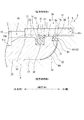
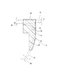
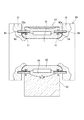
図1は本発明における第一の形態を有する密封構造体を含む軸受装置の一例を示す断面図である。この軸受装置7は、製鋼工程に用いられる連続鋳造機の駆動用のロール3を支持するためのものである。ロール3は、中央の小径軸部4と、その軸方向両側の大径部5とを一体として有しており、杵型である。小径軸部4は、大径部5よりも直径が小さいことから、小径軸部4と一対の大径部5,5との間に環状凹部が形成されており、この環状凹部に軸受装置7が設けられている。以下において、小径軸部4と大径部5との境界部をロール3のネック部3aともいう。ネック部3aは、大径部5から小径軸部4に向かって直径が徐々に小さくなる凹曲面形状(テーパ面形状)を有している。また、大径部5の内側の側面には、環状の凹周溝6が形成されている。
Hereinafter, embodiments of the present invention will be described with reference to the drawings.
[Overall configuration of bearing device]
FIG. 1 is a cross-sectional view showing an example of a bearing device including a sealing structure having a first form according to the present invention. This
ロール3の中心線L0と、軸受装置7の中心線L1とは一致しており、以下において、中心線L1(L0)に平行な方向を軸方向と定義する。また、この軸方向に直交する方向を径方向と定義する。また、軸受装置7を構成する内輪11等の各部の中心線は、軸受装置7の中心線L1と一致する。以下、内輪11の中心線の符号もL1とする。図1は、中心線L1(L0)を含む鉛直な平面における断面図であり、本実施形態の軸受装置7は、図1に示す断面において、左右に二分する垂直な線に対して左右対称の構成を有している。以下において、図1の右側の一部の構成を説明するが、左側においても(左右対称であるが)右側と同じ構成となっている。
The center line L0 of the
軸受装置7は、軸受本体10と密封構造体30とを備えている。軸受本体10は、内輪11、外輪部材12、円筒ころ(転動体)13、及び軸箱14を含む。密封構造体30は軸受本体10の左右両側に設けられており(左右対称であるが)同じ構成である。密封構造体30は、ラビリンスリング31、オイルシール41、及びパッキン(第一パッキン)51を含む。図1に示す密封構造体30には、第二パッキン69が更に含まれる。
The
〔軸受本体10の各部の構成〕
軸箱14は、上下に分割される二分割構造を有している。つまり、軸箱14は、床面に固定される基台17と、この基台17の上に載せられる蓋部材18とを有しており、これらは図外のボルト等によって連結固定される。基台17は、上面側に球面に沿った形状の球面座17aを有している。
[Configuration of each part of the bearing body 10]
The
内輪11は、二分割構造を有している。つまり、内輪11は、半円筒形状である第一内側半筒部11a及び第二内側半筒部11bを有しており、これら内側半筒部11a,11bの分割面は、内輪11の中心線L1を含む平面上にある。内側半筒部11a,11bは図外のボルト等によって連結固定され、一体の筒状部材(内輪11)となり、ロール3の小径軸部4に外嵌して固定された状態となる。内輪11の外周側には、円筒形状である内軌道面11cが設けられており、また、内輪11は、内軌道面11cの軸方向両側に、内軌道面11cよりも直径が大きくなっている肩部20,20を有している。
The
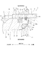
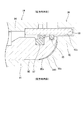
図2は、図1に示す軸受装置7及びロール3の右側の一部を示す断面図である。肩部20の外周面20aは内軌道面11cよりも直径が大きく、この外周面20aに、第一外周溝71と第二外周溝76とが設けられている。これら外周溝71,76はそれぞれ環状の溝であり、第一外周溝71は、オイルシール41の取り付け用の溝であり、第二外周溝76は、第二パッキン69の取り付け用の溝である。
FIG. 2 is a cross-sectional view showing a part of the right side of the
図1において、外輪部材12は、全体として筒形状であるが、上下に分割される二分割構造を有している。つまり、外輪部材12は、半円筒形状である第一外側半筒部12a及び第二外側半筒部12bを有しており、これら外側半筒部12a,12bの分割面は、外輪部材12の中心線を含む平面上にある。なお、組み立て状態で、外輪部材12の中心線は、内輪11の中心線L1と一致する。外側半筒部12a,12bは図外のボルト等によって連結固定され、一体の筒状部材(筒状の外輪部材12)となる。外輪部材12の内周側には、円筒形状である外軌道面12cが設けられている。第一外側半筒部12aは、外輪部材12の下側半分を構成しており、軸箱14の基台17上に載った状態にある。第一外側半筒部12aの下面は、前記球面座17aに対応する形状を有し、球面座17aに載る載置面となる。上側の第二外側半筒部12bは、軸箱14の蓋部材18と一体となっている。
In FIG. 1, the
円筒ころ13は、内軌道面11cと外軌道面12cとの間に介在している。これにより、内輪11と外輪部材12とは同心状に配置される。そして、ロール3が内輪11と共に一体回転することで、円筒ころ13は、内軌道面11c及び外軌道面12cを転動する。
The
以上より、軸受本体10は、杵型ロール3の小径軸部4に外嵌する内輪11、この内輪11の径方向外側に設けられている筒状の外輪部材12、内輪11と外輪部材12との間に設けられている複数の円筒ころ13、及び、外輪部材12を支持している軸箱14を有する構成となる。そして、この軸受装置7は分割型となっている。
As described above, the bearing
〔ラビリンスリング31〕
ラビリンスリング31は、円筒状の部材であるが、上下に分割される二分割構造を有している。つまり、ラビリンスリング31は、半円筒形状である第一半筒部31a及び第二半筒部31bを有しており、これら半筒部31a,31bの分割面は、ラビリンスリング31の中心線を含む平面上にある。なお、組み立て状態で、ラビリンスリング31の中心線は、内輪11の中心線L1と一致する。ラビリンスリング31の下側半分を構成する第一半筒部31aは軸箱14(基台17)に取り付けられており、上側半分を構成する第二半筒部31bは外輪部材12(外側半筒部12b)に取り付けられている。
[Labyrinth ring 31]
The
軸方向一方側(図1において右側)のラビリンスリング31は、軸受本体10から軸方向一方側に向かって突出しており、ラビリンスリング31の一部(軸方向外側部31c)が、ロール3の大径部5に形成されている凹周溝6に入った状態となっている。図2に示すように、ラビリンスリング31の一部(軸方向外側部31c)が凹周溝6に入った状態となることにより、凹周溝6との間にラビリンス隙間を形成し、外部から冷却水がロール3のネック部3aと内輪11との間に浸入するのを抑制する。
また、軸方向他方側(図1において左側)のラビリンスリング31は、軸受本体10から軸方向他方側に向かって突出しており、ラビリンスリング31の一部(軸方向外側部31c)が、ロール3の大径部5に形成されている凹周溝6に入った状態となっている。軸方向他方側においても、軸方向一方側と同様に、ラビリンスリング31の一部(軸方向外側部31c)が凹周溝6に入った状態となることにより、凹周溝6との間にラビリンス隙間を形成し、外部から冷却水がロール3のネック部3aと内輪11との間に浸入するのを抑制する。
以上より、ラビリンスリング31は、内輪11の径方向外側において軸受本体10に取り付けられており、杵型ロール3の大径部5に形成されている凹周溝6に一部が入ってこの凹周溝6との間でラビリンス隙間を形成するための部材である。
The
Further, the
As described above, the
〔オイルシール41〕
図2において、オイルシール41は、環状のシール本体部42と、このシール本体部42から突出しているシールリップ部43とを有しており、これらはゴム製である。シール本体部42は、内輪11の第一外周溝71に嵌って取り付けられている。シールリップ部43は、ラビリンスリング31の内周面32に接触可能であり、ロール3及び内輪11が回転すると、オイルシール41も共に回転し、シールリップ部43がラビリンスリング31の内周面32に滑り接触する。オイルシール41は、全体としてリング状であるが、周方向の一箇所でカットされており、分割構造である内輪11への取り付けを容易としている。このように、オイルシール41は、内輪11の外周側に設けられている第一外周溝71に取り付けられており、ラビリンスリング31の内周面32に滑り接触し、軸受内部15に冷却水が浸入するのを防止するための部材となっている。
[Oil seal 41]
In FIG. 2, the
〔パッキン69及びパッキン51(その1)〕
第二パッキン69について先に説明する。第二パッキン69は、環状のパッキン本体部44と、このパッキン本体部44から突出しているパッキンリップ部45とを有している。パッキン本体部44は、内輪11の第二外周溝76に嵌って取り付けられている。パッキンリップ部45は、ラビリンスリング31の内周面32に接触可能であり、ロール3及び内輪11が回転すると、第二パッキン69も共に回転し、パッキンリップ部45がラビリンスリング31の内周面32に滑り接触する。第二パッキン69は、全体がゴム製であってもよいが、パッキンリップ部45については接触抵抗を低減するために樹脂製としてもよい。また、第二パッキン69は、全体としてリング状であるが、周方向の一箇所でカットされており、分割構造である内輪11への取り付けを容易としている。このように、第二パッキン69は、内輪11の外周側に設けられている第二外周溝76に取り付けられており、ラビリンスリング31の内周面32に滑り接触し、軸受内部15に冷却水が浸入するのを防止するための部材となっている。
[
The
図2に示す第一パッキン51(以下、単にパッキン51ともいう。)について説明する前に、このパッキン51が取り付けられる内輪11の軸方向側部16の形状について説明する。図2に示す形態では、内輪11は、軸方向側部16において、径方向外側から順に、円環面21と、断面凸形の円弧状面22と、円筒面23とを有している。円環面21は、内輪11の中心線L1(図1参照)に直交する仮想面F1上に位置する環状の面である。円弧状面22は、円環面21から連続して形成されており、軸方向中央(図2では左側)に向かうにしたがって縮径する凸曲面形状(テーパ面形状)を有している。なお、図2に示す形態では、円弧状面22は、円環面21との間に、内輪11の中心線L1に直交する仮想面上に位置する第二の円環面22aを有しており、この第二の円環面22aから続いて凸曲面形状が始まっている。円筒面23は、円弧状面22から連続して形成されており、中心線L1を中心とする円筒状の面である。この円筒面23において、内輪11は、ロール3の小径軸部4に嵌合している。
Before describing the first packing 51 shown in FIG. 2 (hereinafter also simply referred to as packing 51), the shape of the
このような形状を有する内輪11の軸方向側部16のうち、円弧状面22に、第一パッキン51用である環状の取り付け溝72が設けられている。図2に示す取り付け溝72は、径方向内側に臨む円筒面72aと、軸方向外側に臨む円環面72bとを有しており、円弧状面22の範囲内に設けられている。
An annular mounting
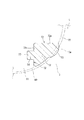
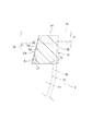
図3は、図1及び図2に示すパッキン51の断面図である。図3において、内輪11及びロール3を仮想線(二点鎖線)で示している。パッキン51は、環状である本体部52と、環状である接触部53とを有している。本体部52は、取り付け溝72に取り付けられている部分であり、接触部53は、本体部52から突出するようにしてロール3側に設けられている部分である。図3では、本体部52と接触部53との境界を破線により示している。接触部53は、ロール3のネック部3aに接触可能となっている。パッキン51はゴム製であり、ネック部3aに接触部53が接触することで弾性変形する。軸受装置7が組み立てられた状態で、接触部53は、ネック部3aに締め代を有して接触した状態となる。ロール3が回転すると、このロール3と共に内輪11及びパッキン51は一体回転する。
FIG. 3 is a cross-sectional view of the packing 51 shown in FIGS. 1 and 2. In FIG. 3, the
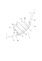
図4は、図3に示すパッキン51の変形例を示す断面図である。なお、取り付け溝72の形状は、図3に示す形態と同じである。図4に示すパッキン51は、図3に示すパッキン51と同様に、取り付け溝72に取り付けられている本体部52と、この本体部52からロール3側に設けられており、ロール3のネック部3aに接触可能である接触部53とを有しているが、接触部53の形態が異なっている。つまり、図3に示すパッキン51の接触部53は、本体部52の軸方向外側領域の一部から突出するようにしてロール3側に設けられているのに対して、図4に示すパッキン51の接触部53は、本体部52の軸方向外側領域の全体から突出するようにしてロール3側に設けられている。
FIG. 4 is a cross-sectional view showing a modification of the packing 51 shown in FIG. The shape of the mounting
図3及び図4に示すパッキン51それぞれは、全体としてリング状であるが、本実施形態では内輪11とあわせて二分割構造を有している。分割されたパッキン51を内輪11に形成されている取り付け溝72に対して容易に取り付けるために、取り付け溝72には凹部77が形成されており、パッキン51の本体部52が有する凸部56が凹部77に嵌合する構成となっている。凹部77は、単独の穴形状を有しており、取り付け溝72に沿って複数形成され、この凹部77の位置にあわせてパッキン51には凸部56が形成されている。なお、第一パッキン51は、オイルシール41及び第二パッキン69と同様に、周方向の一箇所でカットされた構成であってもよい。
Each of the
以上より、図2〜図4に示すパッキン51は、内輪11の軸方向側部16に取り付けられており、ロール3の一部(ネック部3a)に接触することで内輪11とロール3との間に外部から冷却水が浸入するのを防止することができる。特に、内輪11の円弧状面22にパッキン51が取り付けられた構成となり、ロール3のネック3a部との間で止水することができる。
As described above, the packing 51 shown in FIGS. 2 to 4 is attached to the
また、図2〜図4に示す形態では、取り付け溝72は第一外周溝71(図2参照)よりも径方向内側の位置に形成されており、第一外周溝71と取り付け溝72とが軸方向に接近して並んだ構成とならないようにしている。これは、仮に二つの溝71,72が軸方向に接近して並んだ構成とした場合、内輪11の軸方向側部16におけるこれら溝71,72による欠損部が大きくなって強度が低下するが、図2に示す形態によれば、このような軸方向側部16における強度の低下を防ぐことができるためである。
2 to 4, the mounting
パッキン51及び取り付け溝72は、図示した断面形状以外であってもよい。例えば、図3では、本体部52から隆起状となっている接触部53を一つ(一条)としているが、接触部53を複数としてもよい。また、パッキン51の断面形状は円形等であってもよく、その一部を接触部53とすればよい。
また、取り付け溝72は、円弧状面22にのみ形成されている場合について説明したが、円弧状面22から円環面21(22a)の一部にかかって形成されていてもよく、又は、円弧状面22から円筒面23の一部にかかって形成されていてもよい。すなわち、内輪11の軸方向側部16のうちの少なくとも円弧状面22に環状の取り付け溝72が設けられていればよい。
The packing 51 and the mounting
Further, although the case where the mounting
図2〜図4に示す形態の場合、内輪11の軸方向側部16(図2参照)に取り付け溝72が形成されているが、内輪11の中心線L1(図1参照)に直交する仮想面F1上に位置する円環面21が残されている。この円環面21を、内輪11の加工の際に活用することができる。すなわち、内輪11を機械加工する場合、この内輪11の軸方向側部16を(図示しないが)マグネットチャックで保持する。このような加工の際、マグネットチャックにとって内輪11の軸方向側部16には、その中心線L1に直交する面が(少なくとも半径で数ミリメートル)必要である。そこで、図2〜図4に示す形態の場合、取り付け溝72の径方向外側に前記のとおり円環面21が設けられていることから、この円環面21をマグネットチャックのために用いることが可能となり、内輪11の加工を従来のとおり行うことが可能となる。
In the case of the form shown in FIGS. 2 to 4, the mounting
〔パッキン51(その2)〕
図5は、第二の形態を有する密封構造体30を示す断面図である。図5に示す密封構造体30では、図2に示す密封構造体30と比較して、第二パッキン69が省略されている。図5に示す形態では、図2に示す第一パッキン51及び第二パッキン69の機能を、一つのパッキン51が有している。なお、軸受装置7が備えているその他の構成は、図1に示す形態の構成と同じである。
[Packing 51 (Part 2)]
FIG. 5 is a cross-sectional view showing a sealing
図5に示すパッキン51について説明する前に、このパッキン51が取り付けられる内輪11の軸方向側部16の形状について説明する。図5に示す形態では、内輪11は、軸方向側部16において、径方向外側から順に、取り付け溝72と、断面凸形の円弧状面22と、円筒面23とを有している。取り付け溝72は環状の溝であり、パッキン51の取り付け用である。取り付け溝72は、径方向外側に臨む外側円筒面78と、軸方向外側に臨む円環面79とからなる。円弧状面22は、取り付け溝72から連続して形成されており、軸方向中央(図5では左側)に向かうにしたがって縮径する凸曲面形状(テーパ面形状)を有している。なお、図5に示す形態では、円弧状面22は、取り付け溝72との間に、内輪11の中心線L1に直交する仮想面上に位置する第二の円環面を有していてもよく、この第二の円環面から続いて凸曲面形状が始まっていてもよい。円筒面23は、円弧状面22から連続して形成されており、中心線L1を中心とする円筒状の面である。この円筒面23において、内輪11は、ロール3の小径軸部4に嵌合している。
Before describing the packing 51 shown in FIG. 5, the shape of the
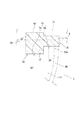
図6は、図5に示すパッキン51の断面図である。図6において、ラビリンスリング31、内輪11及びロール3を仮想線(二点鎖線)で示している。パッキン51は、環状である本体部52と、環状である第一接触部54と、環状である第二接触部55とを有している。本体部52は、取り付け溝72に取り付けられている部分であり、第一接触部54は、本体部52から径方向に突出するようにしてラビリンスリング31側に設けられている部分であり、第二接触部55は、本体部52から軸方向に突出するようにしてロール3側に設けられている部分である。図6では、本体部52と第一接触部54との境界及び本体部52と第二接触部55との境界をそれぞれ破線により示している。第一接触部54は、ラビリンスリング31の内周面32に滑り接触可能となっており、第二接触部55は、ロール3に接触可能となっている。
6 is a cross-sectional view of the packing 51 shown in FIG. In FIG. 6, the
パッキン51は、断面四角形(台形)であり、パッキン51の外周部が第一接触部54であり、パッキン51の軸方向側部が第二接触部55となっている。パッキン51はゴム製であり、ラビリンスリング31に第一接触部54が接触することで径方向に弾性変形し、ロール3に第二接触部55が接触することで軸方向に弾性変形する。軸受装置7が組み立てられた状態で、第一接触部54は、ラビリンスリング31に締め代を有して接触した状態となり、第二接触部55は、ロール3に締め代を有して接触した状態となる。ロール3が回転すると、このロール3と共に内輪11及びパッキン51は一体回転し、第一接触部54はラビリンスリング31に滑り接触するのに対して、第二接触部55はロール3と相対的な位置変化することなく接触した状態となる。
The packing 51 has a quadrangular cross section (trapezoid), the outer peripheral portion of the packing 51 is a
取り付け溝72において、外側円筒面78は、内輪11の中心線L1(図1参照)を中心とする円筒形状の面であり、円環面79は、外側円筒面78に対して傾斜しており、傾斜角度Kは90度未満となっている。そして、パッキン51の本体部52は、この傾斜している円環面79に面で接触する傾斜面52aを有している。この構成により、パッキン51が径方向外側に脱落するのを防ぐことが可能となる。
In the mounting
図7は、図5に示すパッキン51の変形例を示す断面図である。図7に示す形態においても、図5の場合と同様に、図2に示す第一パッキン51及び第二パッキン69の機能を、一つのパッキン51が有している。
FIG. 7 is a cross-sectional view showing a modification of the packing 51 shown in FIG. Also in the form shown in FIG. 7, as in the case of FIG. 5, the
図7に示すパッキン51について説明する前に、このパッキン51が取り付けられる内輪11の軸方向側部16の形状について説明する。図7に示す形態では、内輪11は、軸方向側部16において、径方向外側から順に、取り付け溝72と、断面凸形の円弧状面22と、円筒面23とを有している。取り付け溝72は環状の溝であり、パッキン51の取り付け用である。取り付け溝72は、軸方向外側(図7では右側)の第一溝部74と、この第一溝部74に対して軸方向中央側に設けられている第二溝部75とを有している。第二溝部75は、第一溝部74よりも溝底の直径が小さい(図8において、第二溝部75の溝底の直径D2<第一溝部74の溝底の直径D1)。図7において、円弧状面22は、取り付け溝72から連続して形成されており、軸方向中央(図7では左側)に向かうにしたがって縮径する凸曲面形状(テーパ面形状)を有している。なお、図7に示す形態では、円弧状面22は、取り付け溝72との間に、内輪11の中心線L1に直交する仮想面上に位置する第二の円環面22aを有しており、この第二の円環面22aから続いて凸曲面形状が始まっている。円筒面23は、円弧状面22から連続して形成されており、中心線L1を中心とする円筒状の面である。この円筒面23において、内輪11は、ロール3の小径軸部4に嵌合している。
Before describing the packing 51 shown in FIG. 7, the shape of the
図8は、図7に示すパッキン51の断面図である。図8において、ラビリンスリング31、内輪11及びロール3を仮想線(二点鎖線)で示している。パッキン51は、環状である本体部52と、環状である第一接触部54と、環状である第二接触部55とを有している。本体部52は、取り付け溝72に取り付けられている部分である。第一接触部54は、本体部52から径方向に突出するようにしてラビリンスリング31側に設けられている部分であり、第二接触部55は、本体部52から軸方向に突出するようにしてロール3側に設けられている部分である。図8では、本体部52と第一接触部54との境界及び本体部52と第二接触部55との境界をそれぞれ破線により示している。第一接触部54は、ラビリンスリング31の内周面32に滑り接触可能となっており、第二接触部55は、ロール3に接触可能となっている。
FIG. 8 is a cross-sectional view of the packing 51 shown in FIG. In FIG. 8, the
パッキン51について更に説明すると、パッキン51は、第一溝部74及び第二溝部75に嵌まる本体部52と、本体部52から径方向外側の第一接触部54と、本体部52から軸方向外側に延びて設けられている第二接触部55とを有している。パッキン51はゴム製であり、ラビリンスリング31に第一接触部54が接触することで径方向に弾性変形し、ロール3に第二接触部55が接触することで軸方向に弾性変形する。軸受装置7が組み立てられた状態で、第一接触部54は、ラビリンスリング31に締め代を有して接触した状態となり、第二接触部55は、ロール3に締め代を有して接触した状態となる。ロール3が回転すると、このロール3と共に内輪11及びパッキン51は一体回転し、第一接触部54はラビリンスリング31に滑り接触するのに対して、第二接触部55はロール3と相対的な位置変化することなく接触した状態となる。
The packing 51 will be further described. The packing 51 includes a
図5〜図8に示すパッキン51それぞれは、全体としてリング状であり、内輪11とあわせて二分割構造であってもよいが、本実施形態では、オイルシール41と同様に、周方向の一箇所でカットされた構成である。
Each of the
以上より、図5〜図8に示すパッキン51は、内輪11の軸方向側部16に取り付けられており、ロール3の一部(大径部5)に接触することで内輪11とロール3との間に外部から冷却水が浸入するのを防止することができる。更に、パッキン51は、内輪11とロール3との間に外部から冷却水が浸入するのを防止する機能の他に、ラビリンスリング31と内輪11との間から冷却水が浸入するのを防止する機能も有することができる。つまり、一つのパッキン51で二つの止水機能を有することができ、図2に示す形態と比較して、パッキン69を省略することで部品点数の削減が行われている。
また、図6に示す形態では、前記のとおりパッキン51は断面四角形(台形)である。このため、パッキン51の形状が簡単であり、密封構造体30の簡素化が可能となる。
図8に示す形態では、パッキン51の本体部52は、段付き形状となる第一溝部74及び第二溝部75に嵌まることで、安定した取り付け状態が得られ、パッキン51の脱落を抑制することが可能となる。
As described above, the packing 51 shown in FIGS. 5 to 8 is attached to the
Moreover, in the form shown in FIG. 6, the packing 51 is a square cross section (trapezoid) as mentioned above. For this reason, the shape of the packing 51 is simple, and the sealing
In the form shown in FIG. 8, the
〔パッキン51(その3)〕
図9は、第三の形態を有する密封構造体30を示す断面図である。図9に示す密封構造体30では、図2に示す密封構造体30と比較して、第二パッキン69が省略されている。図9に示す形態では、図2に示す第一パッキン51及び第二パッキン69の機能を、一つのパッキン51が有している。なお、軸受装置7が備えているその他の構成は、図1に示す形態の構成と同じである。
[Packing 51 (Part 3)]
FIG. 9 is a cross-sectional view showing a sealing
図9に示すパッキン51について説明する前に、このパッキン51が取り付けられる内輪11の軸方向側部16の形状について説明する。図9に示す形態では、内輪11は、軸方向側部16において、径方向外側から順に、取り付け溝72と、円環面24と、断面凸形の円弧状面22と、円筒面23とを有している。取り付け溝72は環状の溝であり、パッキン51の取り付け用である。円環面24は、内輪11の中心線L1(図1参照)に直交する仮想面F2上に位置する環状の面である。円弧状面22は、円環面21から連続して形成されており、軸方向中央(図9では左側)に向かうにしたがって縮径する凸曲面形状(テーパ面形状)を有している。円筒面23は、円弧状面22から連続して形成されており、中心線L1を中心とする円筒状の面である。この円筒面23において、内輪11は、ロール3の小径軸部4に嵌合している。
Before describing the packing 51 shown in FIG. 9, the shape of the
図10は、パッキン51の断面図である。図10において、ラビリンスリング31、内輪11及びロール3を仮想線(二点鎖線)で示している。パッキン51は、環状である本体部52と、環状である第一接触部54と、環状である第二接触部55とを有している。本体部52は、取り付け溝72に取り付けられていると共に円環面24を軸方向から覆っている部分である。第一接触部54は、本体部52から径方向に突出するようにしてラビリンスリング31側に設けられている部分であり、第二接触部55は、本体部52から軸方向に突出するようにしてロール3側に設けられている部分である。図10では、本体部52と第一接触部54との境界及び本体部52と第二接触部55との境界をそれぞれ破線により示している。第一接触部54は、ラビリンスリング31の内周面32に滑り接触可能となっており、第二接触部55は、ロール3に接触可能となっている。
FIG. 10 is a cross-sectional view of the packing 51. In FIG. 10, the
パッキン51はゴム製であり、ラビリンスリング31に第一接触部54が接触することで径方向に弾性変形し、ロール3に第二接触部55が接触することで軸方向に弾性変形する。軸受装置7が組み立てられた状態で、第一接触部54は、ラビリンスリング31に締め代を有して接触した状態となり、第二接触部55は、ロール3に締め代を有して接触した状態となる。ロール3が回転すると、このロール3と共に内輪11及びパッキン51は一体回転し、第一接触部54はラビリンスリング31に滑り接触するのに対して、第二接触部55はロール3と相対的な位置変化することなく接触した状態となる。
The packing 51 is made of rubber, and elastically deforms in the radial direction when the
図9及び図10に示すパッキン51は、全体としてリング状であり、内輪11とあわせて二分割構造であってもよいが、本実施形態では、オイルシール41と同様に、周方向の一箇所でカットされた構成である。
The packing 51 shown in FIGS. 9 and 10 has a ring shape as a whole and may have a two-part structure together with the
以上より、このパッキン51は、内輪11の軸方向側部16に取り付けられており、ロール3の一部(大径部5)に接触することで内輪11とロール3との間に外部から冷却水が浸入するのを防止することができる。更に、パッキン51は、内輪11とロール3との間に外部から冷却水が浸入するのを防止する機能の他に、ラビリンスリング31と内輪11との間から冷却水が浸入するのを防止する機能も有することができる。つまり、一つのパッキン51で二つの止水機能を有することができ、図2に示す形態と比較して、パッキン69を省略することで部品点数の削減が行われている。
As described above, the packing 51 is attached to the
なお、図9及び図10に示す形態の場合、内輪11の軸方向側部16に取り付け溝72が形成されているが、更に、内輪11の中心線L1(図1参照)に直交する仮想面F2上に位置する円環面24も形成されている。この円環面24を、内輪11の加工の際に活用することができる。すなわち、内輪11を機械加工する場合、この内輪11の軸方向側部16を(図示しないが)マグネットチャックで保持する。このような加工の際、マグネットチャックにとって内輪11の軸方向側部16には、その中心線L1に直交する面が(少なくとも半径で数ミリメートル)必要である。そこで、図9及び図10に示す形態の場合、取り付け溝72の径方向内側に前記のとおり円環面24が設けられていることから、この円環面24をマグネットチャックのために用いることが可能となり、内輪11の加工を従来のとおり行うことが可能となる。
9 and 10, the mounting
〔各形態のパッキン51を有する軸受装置7〕
以上より、軸受装置7は、軸受本体10と密封構造体30とを備えている。軸受本体10(図1参照)は、軸箱14に対して杵型ロール3を回転可能として支持するために、このロール3の小径軸部4に装着される。密封構造体30は、ラビリンスリング31、オイルシール41及びパッキン51を有しており、この密封構造体30によれば、円筒ころ13が設けられている軸受内部15、及び、内輪11とロール3との間に外部から冷却水が浸入するのを防止することができる。つまり、内輪11の軸方向側部16に設けられているオイルシール41がラビリンスリング31に接触して、軸受内部15に冷却水が浸入するのを防止し、更に、内輪11の軸方向側部16に取り付けられているパッキン51が、ロール3の一部に接触して内輪11とロール3との間に外部から冷却水が浸入するのを防止している。この結果、内輪11とロール3との間の隙間80に冷却水が滞留しないようにして腐食の発生を防ぐことが可能となる。
[
As described above, the
以上のとおり開示した実施形態はすべての点で例示であって制限的なものではない。つまり、本発明の軸受装置及び密封装置は、図示する形態に限らず本発明の範囲内において他の形態のものであってもよい。
前記実施形態では、軸受装置7を、連続鋳造機の駆動用のロール3を支持するためのものとして説明したが、ロールと内輪との間の隙間に水等の異物が浸入するのを防ぐことを目的として、他の用途に前記各構成を備えている軸受装置7を用いても良い。
また、パッキン51は、全体が同じ材質のゴムによって形成されていてもよいが、複数種類の材質によって形成されたものであってもよい。例えば、本体部52はゴム製であるが、接触部(53,54,55)は本体部52よりも摩擦係数の小さい部材(例えば樹脂部材)であってもよい。
The embodiments disclosed above are illustrative in all respects and not restrictive. That is, the bearing device and the sealing device of the present invention are not limited to the illustrated forms, and may be in other forms within the scope of the present invention.
In the above-described embodiment, the
Further, the packing 51 may be formed of the same material rubber as a whole, but may be formed of a plurality of types of materials. For example, the
3:杵型ロール 4:小径軸部 5:大径部
6:凹周溝 7:軸受装置 10:軸受本体
11:内輪 12:外輪部材 13:円筒ころ(転動体)
14:軸箱 15:軸受内部 16:軸方向側部
21:円環面 22:円弧状面 23:円筒面
24:円環面 30:密封構造体 31:ラビリンスリング
32:内周面 41:オイルシール 51:第一パッキン(パッキン)
52:本体部 53:接触部 54:第一接触部
55:第二接触部 71:第一外周溝 72:取り付け溝
74:第一溝部 75:第二溝部 78:外側円筒面(円筒面)
79:円環面 80:隙間 L1:内輪の中心線
F1:仮想面 F2:仮想面
3: Vertical roll 4: Small diameter shaft 5: Large diameter 6: Concave groove 7: Bearing device 10: Bearing body 11: Inner ring 12: Outer ring member 13: Cylindrical roller (rolling element)
14: Shaft box 15: Bearing interior 16: Axial side portion 21: Annular surface 22: Circular surface 23: Cylindrical surface 24: Annular surface 30: Sealing structure 31: Labyrinth ring 32: Inner peripheral surface 41: Oil Seal 51: First packing (packing)
52: Body part 53: Contact part 54: First contact part 55: Second contact part 71: First outer peripheral groove 72: Mounting groove 74: First groove part 75: Second groove part 78: Outer cylindrical surface (cylindrical surface)
79: Annular surface 80: Clearance L1: Center line of inner ring F1: Virtual surface F2: Virtual surface
Claims (7)
前記転動体が設けられている軸受内部、及び、前記内輪と前記ロールとの間に、外部から水が浸入するのを防止するための密封構造体と、
を備えた軸受装置であって、
前記密封構造体は、
前記内輪の径方向外側において前記軸受本体に取り付けられ前記ロールの大径部に形成されている凹周溝に一部が入って当該凹周溝との間でラビリンス隙間を形成するラビリンスリングと、
前記内輪の軸方向側部に取り付けられ前記ロールの一部に接触し当該内輪と当該ロールとの間に外部から水が浸入するのを防止するためのパッキンと、を有している、軸受装置。 An inner ring that is externally fitted to the small-diameter shaft portion of a saddle type roll having a small-diameter shaft portion and a large-diameter portion, a cylindrical outer ring member that is provided on the radially outer side of the inner ring, and a space between the inner ring and the outer ring member A plurality of rolling elements, and a bearing body having a shaft box supporting the outer ring member;
A sealing structure for preventing water from entering from the inside between the bearing in which the rolling element is provided and between the inner ring and the roll;
A bearing device comprising:
The sealing structure is
A labyrinth ring which is attached to the bearing body on the radially outer side of the inner ring and a labyrinth gap is formed between the concave circumferential groove and a part of the concave circumferential groove formed in the large diameter portion of the roll;
A bearing device having a packing attached to an axial side portion of the inner ring and contacting a part of the roll to prevent water from entering between the inner ring and the roll from the outside. .
前記内輪の前記軸方向側部のうちの少なくとも前記円弧状面に環状の取り付け溝が設けられており、
前記パッキンは、前記取り付け溝に取り付けられている本体部と、当該本体部から前記ロール側に設けられ当該ロールに接触可能である接触部と、を有している、請求項1に記載の軸受装置。 The inner ring has an annular surface located on a virtual plane perpendicular to the center line of the inner ring, and an arcuate surface that decreases in diameter toward the center in the axial direction, from the radially outer side in the axial direction side portion, A cylindrical surface fitted to the small-diameter shaft portion,
An annular mounting groove is provided on at least the arcuate surface of the axial side portion of the inner ring,
The bearing according to claim 1, wherein the packing includes a main body portion attached to the attachment groove, and a contact portion provided on the roll side from the main body portion and capable of contacting the roll. apparatus.
前記パッキンは、前記取り付け溝に取り付けられている本体部と、当該本体部から前記ラビリンスリング側に設けられ当該ラビリンスリングの内周面に滑り接触可能である第一接触部と、前記本体部から前記ロール側に設けられ当該ロールに接触可能である第二接触部と、を有している、請求項1に記載の軸受装置。 The inner ring includes an annular mounting groove, an arc-shaped surface that decreases in diameter toward the center in the axial direction, and a cylindrical surface that is fitted to the small-diameter shaft portion on the axial side portion from the radially outer side. Have
The packing includes a main body part attached to the attachment groove, a first contact part provided on the labyrinth ring side from the main body part and capable of sliding contact with an inner peripheral surface of the labyrinth ring, and the main body part. The bearing device according to claim 1, further comprising: a second contact portion provided on the roll side and capable of contacting the roll.
前記パッキンは、断面四角形であり、当該パッキンの外周部が前記第一接触部であり、当該パッキンの軸方向側部が前記第二接触部である、請求項3に記載の軸受装置。 The mounting groove consists of a cylindrical surface facing the radially outer side and an annular surface facing the axially outer side,
The bearing device according to claim 3, wherein the packing has a quadrangular cross section, an outer peripheral portion of the packing is the first contact portion, and an axial side portion of the packing is the second contact portion.
前記パッキンは、前記第一溝部及び前記第二溝部に嵌まる前記本体部と、当該本体部から径方向外側に延びて設けられている前記第一接触部と、前記本体部から軸方向外側に延びて設けられている前記第二接触部と、を有している請求項3に記載の軸受装置。 The attachment groove has a first groove portion on the outer side in the axial direction, and a second groove portion that is provided adjacent to the first groove portion and has a smaller groove bottom diameter than the first groove portion,
The packing includes the main body portion that fits in the first groove portion and the second groove portion, the first contact portion that extends radially outward from the main body portion, and the axially outer side from the main body portion. The bearing device according to claim 3, further comprising: the second contact portion that extends.
前記パッキンは、前記取り付け溝に取り付けられていると共に前記円環面を覆っている本体部と、当該本体部から前記ラビリンスリング側に設けられ当該ラビリンスリングの内周面に滑り接触可能である第一接触部と、前記本体部から前記ロール側に設けられ当該ロールに接触可能である第二接触部と、を有している、請求項1に記載の軸受装置。 The inner ring has an annular mounting groove, an annular surface located on a virtual plane orthogonal to the center line of the inner ring, and a diameter decreasing toward the axial center from the radially outer side at the axial side portion. An arcuate surface to be engaged with, and a cylindrical surface fitted to the small-diameter shaft portion,
The packing is attached to the attachment groove and covers the annular surface, and the packing is provided on the labyrinth ring side from the main body portion and is capable of sliding contact with an inner peripheral surface of the labyrinth ring. The bearing device according to claim 1, further comprising: one contact portion; and a second contact portion that is provided on the roll side from the main body portion and is capable of contacting the roll.
前記内輪の前記軸方向側部に形成されている取り付け溝に取り付けられる本体部と、
当該本体部から前記ロール側に設けられ当該ロールの一部に接触可能である接触部と、
を有している、密封装置。 Provided on the axial side of the inner ring of the bearing device mounted on the small-diameter shaft portion of the roll for supporting the saddle type roll with respect to the axle box so as to be rotatable, and externally between the inner ring and the roll. A sealing device for preventing water from entering,
A main body attached to an attachment groove formed on the axial side of the inner ring;
A contact portion provided on the roll side from the main body portion and capable of contacting a part of the roll;
Having a sealing device.
Priority Applications (4)
| Application Number | Priority Date | Filing Date | Title |
|---|---|---|---|
| JP2016080952A JP6710566B2 (en) | 2016-04-14 | 2016-04-14 | Bearing device, assembly, and sealing device |
| DE102017107843.6A DE102017107843A1 (en) | 2016-04-14 | 2017-04-11 | Bearing device and sealing device |
| KR1020170047155A KR102278481B1 (en) | 2016-04-14 | 2017-04-12 | Bearing device and sealing device |
| CN201710235540.1A CN107420434B (en) | 2016-04-14 | 2017-04-12 | Bearing device and sealing device |
Applications Claiming Priority (1)
| Application Number | Priority Date | Filing Date | Title |
|---|---|---|---|
| JP2016080952A JP6710566B2 (en) | 2016-04-14 | 2016-04-14 | Bearing device, assembly, and sealing device |
Related Child Applications (1)
| Application Number | Title | Priority Date | Filing Date |
|---|---|---|---|
| JP2020009182A Division JP6814897B2 (en) | 2020-01-23 | 2020-01-23 | Bearing equipment, sealing equipment, and assemblies |
Publications (3)
| Publication Number | Publication Date |
|---|---|
| JP2017190835A true JP2017190835A (en) | 2017-10-19 |
| JP2017190835A5 JP2017190835A5 (en) | 2019-03-28 |
| JP6710566B2 JP6710566B2 (en) | 2020-06-17 |
Family
ID=59980776
Family Applications (1)
| Application Number | Title | Priority Date | Filing Date |
|---|---|---|---|
| JP2016080952A Active JP6710566B2 (en) | 2016-04-14 | 2016-04-14 | Bearing device, assembly, and sealing device |
Country Status (4)
| Country | Link |
|---|---|
| JP (1) | JP6710566B2 (en) |
| KR (1) | KR102278481B1 (en) |
| CN (1) | CN107420434B (en) |
| DE (1) | DE102017107843A1 (en) |
Cited By (4)
| Publication number | Priority date | Publication date | Assignee | Title |
|---|---|---|---|---|
| CN110883099A (en) * | 2019-12-11 | 2020-03-17 | 广东冠邦科技有限公司 | Sealing system and planetary rolling mill |
| CN112718871A (en) * | 2020-12-11 | 2021-04-30 | 陕西龙门钢铁有限责任公司 | Rod and wire mill bearing seal assembly |
| WO2024009459A1 (en) * | 2022-07-07 | 2024-01-11 | 株式会社ジェイテクト | Rolling bearing device |
| KR20250021544A (en) | 2022-07-07 | 2025-02-13 | 가부시키가이샤 제이텍트 | Cloud bearing device |
Families Citing this family (1)
| Publication number | Priority date | Publication date | Assignee | Title |
|---|---|---|---|---|
| TWI693354B (en) * | 2018-11-15 | 2020-05-11 | 臣庭貿易有限公司 | Sealing device |
Citations (6)
| Publication number | Priority date | Publication date | Assignee | Title |
|---|---|---|---|---|
| JPH04302714A (en) * | 1991-03-29 | 1992-10-26 | Ntn Corp | Sealing device of roller bearing |
| JPH066753U (en) * | 1992-06-26 | 1994-01-28 | 光洋精工株式会社 | Split type rotary bearing unit |
| JPH066751U (en) * | 1992-06-30 | 1994-01-28 | エヌティエヌ株式会社 | Sealing device for split rolling bearings |
| JP2001099172A (en) * | 1999-09-27 | 2001-04-10 | Ntn Corp | Drive wheel support device |
| JP2005315340A (en) * | 2004-04-28 | 2005-11-10 | Nsk Ltd | Sealing means for rolling bearing unit Rolling bearing unit |
| JP2007040519A (en) * | 2005-07-04 | 2007-02-15 | Nsk Ltd | Split type rolling bearing unit |
Family Cites Families (5)
| Publication number | Priority date | Publication date | Assignee | Title |
|---|---|---|---|---|
| US1778391A (en) * | 1927-12-08 | 1930-10-14 | Kendall Edgar Homer | Bearing mounting |
| CN85107199A (en) * | 1985-09-26 | 1987-04-08 | 埃默森电气公司 | Bearing unit |
| DE8536143U1 (en) * | 1985-12-21 | 1986-02-20 | SKF Gleitlager GmbH, 6625 Püttlingen | Arrangement for sealing bearings, in particular spherical plain bearings with an outer ring composed of two half-shells |
| CN201627824U (en) * | 2010-04-13 | 2010-11-10 | 景喜原 | Automobile composite joint bearing with outer spherical surface |
| JP6236878B2 (en) | 2013-05-29 | 2017-11-29 | 株式会社ジェイテクト | Split bearing device |
-
2016
- 2016-04-14 JP JP2016080952A patent/JP6710566B2/en active Active
-
2017
- 2017-04-11 DE DE102017107843.6A patent/DE102017107843A1/en active Pending
- 2017-04-12 CN CN201710235540.1A patent/CN107420434B/en active Active
- 2017-04-12 KR KR1020170047155A patent/KR102278481B1/en active Active
Patent Citations (6)
| Publication number | Priority date | Publication date | Assignee | Title |
|---|---|---|---|---|
| JPH04302714A (en) * | 1991-03-29 | 1992-10-26 | Ntn Corp | Sealing device of roller bearing |
| JPH066753U (en) * | 1992-06-26 | 1994-01-28 | 光洋精工株式会社 | Split type rotary bearing unit |
| JPH066751U (en) * | 1992-06-30 | 1994-01-28 | エヌティエヌ株式会社 | Sealing device for split rolling bearings |
| JP2001099172A (en) * | 1999-09-27 | 2001-04-10 | Ntn Corp | Drive wheel support device |
| JP2005315340A (en) * | 2004-04-28 | 2005-11-10 | Nsk Ltd | Sealing means for rolling bearing unit Rolling bearing unit |
| JP2007040519A (en) * | 2005-07-04 | 2007-02-15 | Nsk Ltd | Split type rolling bearing unit |
Cited By (5)
| Publication number | Priority date | Publication date | Assignee | Title |
|---|---|---|---|---|
| CN110883099A (en) * | 2019-12-11 | 2020-03-17 | 广东冠邦科技有限公司 | Sealing system and planetary rolling mill |
| CN112718871A (en) * | 2020-12-11 | 2021-04-30 | 陕西龙门钢铁有限责任公司 | Rod and wire mill bearing seal assembly |
| WO2024009459A1 (en) * | 2022-07-07 | 2024-01-11 | 株式会社ジェイテクト | Rolling bearing device |
| KR20250021544A (en) | 2022-07-07 | 2025-02-13 | 가부시키가이샤 제이텍트 | Cloud bearing device |
| KR20250034425A (en) | 2022-07-07 | 2025-03-11 | 가부시키가이샤 제이텍트 | Cloud bearing device |
Also Published As
| Publication number | Publication date |
|---|---|
| KR20170117882A (en) | 2017-10-24 |
| JP6710566B2 (en) | 2020-06-17 |
| CN107420434A (en) | 2017-12-01 |
| KR102278481B1 (en) | 2021-07-16 |
| CN107420434B (en) | 2020-10-16 |
| DE102017107843A1 (en) | 2017-10-19 |
Similar Documents
| Publication | Publication Date | Title |
|---|---|---|
| JP6293444B2 (en) | Rolling bearing sealing device | |
| KR20160055064A (en) | Sealing device | |
| JP2017190835A (en) | Bearing device and sealing device | |
| JP6841067B2 (en) | Ball bearing | |
| KR101483871B1 (en) | Tilting Insensitive Seal Bearing And The Design Method Thereof | |
| JP7151533B2 (en) | hub unit bearing | |
| WO2016188400A1 (en) | Bearing | |
| EP2078877B1 (en) | Bearing with lubricating means | |
| JP6814897B2 (en) | Bearing equipment, sealing equipment, and assemblies | |
| JP6186833B2 (en) | Rolling bearing with seal ring | |
| JP7225703B2 (en) | tapered roller bearing | |
| CN103573829A (en) | Bearing with sealing slinger | |
| JP2019086077A (en) | Deep groove ball bearings | |
| JP5926061B2 (en) | Sealed rolling bearing | |
| CN109958719B (en) | Bearings with contact seals | |
| JP7243278B2 (en) | Inclined cage and angular contact ball bearing | |
| JP5315881B2 (en) | Rolling bearing | |
| JP6968044B2 (en) | Bearing device for wheels | |
| JP2016070306A (en) | Sealed roller bearing | |
| JP2017015121A (en) | Rolling bearing | |
| KR102889076B1 (en) | Vehicular wheel bearing comprising improved sealing device | |
| JP2005315313A (en) | Sealing structure of bearing | |
| WO2024009453A1 (en) | Rolling bearing device | |
| JP6606903B2 (en) | Rolling bearing | |
| JP2013194880A (en) | Rolling bearing |
Legal Events
| Date | Code | Title | Description |
|---|---|---|---|
| A521 | Request for written amendment filed |
Free format text: JAPANESE INTERMEDIATE CODE: A523 Effective date: 20190118 |
|
| A711 | Notification of change in applicant |
Free format text: JAPANESE INTERMEDIATE CODE: A711 Effective date: 20190118 |
|
| A521 | Request for written amendment filed |
Free format text: JAPANESE INTERMEDIATE CODE: A523 Effective date: 20190124 |
|
| A621 | Written request for application examination |
Free format text: JAPANESE INTERMEDIATE CODE: A621 Effective date: 20190130 |
|
| A521 | Request for written amendment filed |
Free format text: JAPANESE INTERMEDIATE CODE: A821 Effective date: 20190118 |
|
| A977 | Report on retrieval |
Free format text: JAPANESE INTERMEDIATE CODE: A971007 Effective date: 20191121 |
|
| A131 | Notification of reasons for refusal |
Free format text: JAPANESE INTERMEDIATE CODE: A131 Effective date: 20191203 |
|
| A521 | Request for written amendment filed |
Free format text: JAPANESE INTERMEDIATE CODE: A523 Effective date: 20200123 |
|
| TRDD | Decision of grant or rejection written | ||
| A01 | Written decision to grant a patent or to grant a registration (utility model) |
Free format text: JAPANESE INTERMEDIATE CODE: A01 Effective date: 20200512 |
|
| A61 | First payment of annual fees (during grant procedure) |
Free format text: JAPANESE INTERMEDIATE CODE: A61 Effective date: 20200527 |
|
| R150 | Certificate of patent or registration of utility model |
Ref document number: 6710566 Country of ref document: JP Free format text: JAPANESE INTERMEDIATE CODE: R150 |