JP2017190825A - motor - Google Patents
motor Download PDFInfo
- Publication number
- JP2017190825A JP2017190825A JP2016080046A JP2016080046A JP2017190825A JP 2017190825 A JP2017190825 A JP 2017190825A JP 2016080046 A JP2016080046 A JP 2016080046A JP 2016080046 A JP2016080046 A JP 2016080046A JP 2017190825 A JP2017190825 A JP 2017190825A
- Authority
- JP
- Japan
- Prior art keywords
- shaft
- elastic member
- rolling bearing
- outer ring
- casing
- Prior art date
- Legal status (The legal status is an assumption and is not a legal conclusion. Google has not performed a legal analysis and makes no representation as to the accuracy of the status listed.)
- Granted
Links
Images
Landscapes
- Support Of The Bearing (AREA)
- Mounting Of Bearings Or Others (AREA)
- Motor Or Generator Frames (AREA)
- Connection Of Motors, Electrical Generators, Mechanical Devices, And The Like (AREA)
Abstract
【課題】外輪の連れ回りを簡単な構成で抑制したモータを提供する。【解決手段】本発明のモータ1は、シャフト11と、シャフト11の一端側の外周面側に位置する第1内輪13a及び第1内輪13aの外側に位置する第1外輪13bを有する第1転がり軸受13と、シャフト11の他端側の外周面側に位置する第2内輪14a及び第2内輪14aの外側に位置する第2外輪14bを有する第2転がり軸受14と、第1転がり軸受13及び第2転がり軸受14を収容するケーシング30と、第1転がり軸受13の一端側に配置され、第1転がり軸受13及び第2転がり軸受14に予圧を付与する弾性部材40と、を含み、第1転がり軸受13は、第1外輪13bがケーシング30に隙間嵌めされており、弾性部材40は、第1外輪13bを他端側に付勢する付勢力を発生する本体部41と、第1外輪13bを挟持する挟持部42と、を備える。【選択図】図1Provided is a motor in which the rotation of an outer ring is suppressed with a simple configuration. A motor 1 of the present invention includes a shaft 11, a first inner ring 13a located on the outer peripheral surface side of one end of the shaft 11, and a first outer ring 13b located outside the first inner ring 13a. A second rolling bearing 14 having a bearing 13, a second inner ring 14a located on the outer peripheral surface side of the other end of the shaft 11 and a second outer ring 14b located outside the second inner ring 14a, a first rolling bearing 13 and A casing 30 that houses the second rolling bearing 14; and an elastic member 40 that is disposed on one end side of the first rolling bearing 13 and applies preload to the first rolling bearing 13 and the second rolling bearing 14; In the rolling bearing 13, the first outer ring 13 b is fitted in the casing 30 with a gap, and the elastic member 40 includes a main body 41 that generates a biasing force that biases the first outer ring 13 b toward the other end, and the first outer ring 13 b. The Comprising a clamping portion 42 for lifting, the. [Selection] Figure 1
Description
本発明はモータに関する。 The present invention relates to a motor.
特許文献1には、回転軸に設けられた軸受に予圧ばねで予圧を付与するようにしたモータが開示されている(特許文献1参照)。
ところで、スプリングを用いた予圧方式では、シャフトに軸受の内輪を固定し、軸受の外輪をケーシング等に隙間嵌めするようにして、その外輪をスプリングで付勢することが行われているが、内輪の回転によって、外輪が連れ回るクリープ現象が発生する場合がある。
そして、このようなクリープ現象が発生すると、軸受の外輪とケーシング等との間に摩耗が生じるといった問題がある。
By the way, in the preload system using a spring, an inner ring of a bearing is fixed to a shaft, and the outer ring of the bearing is fitted into a gap in a casing or the like, and the outer ring is urged by a spring. Rotation of the outer ring may cause a creep phenomenon that the outer ring rotates.
When such a creep phenomenon occurs, there is a problem that wear occurs between the outer ring of the bearing and the casing.
本発明は、上記事情に鑑みてなされたものであり、外輪の連れ回りを簡単な構成で抑制したモータを提供することを目的とする。 The present invention has been made in view of the above circumstances, and an object thereof is to provide a motor in which the rotation of the outer ring is suppressed with a simple configuration.
本発明は、上記目的を達成するために、以下の構成によって把握される。
(1)本発明のモータは、シャフトと、前記シャフトの軸方向における一端側に設けられ、前記シャフトの外周面側に位置する第1内輪及び前記第1内輪の径方向外側に位置する第1外輪を有する第1転がり軸受と、前記シャフトの軸方向における他端側に設けられ、前記シャフトの外周面側に位置する第2内輪及び前記第2内輪の径方向外側に位置する第2外輪を有する第2転がり軸受と、前記第1転がり軸受及び前記第2転がり軸受を収容するケーシングと、前記第1転がり軸受の前記シャフトの軸方向における一端側に配置され、前記第1転がり軸受及び前記第2転がり軸受に予圧を付与する弾性部材と、を含み、前記第1転がり軸受は、前記第1外輪が前記ケーシングに隙間嵌めされており、前記弾性部材は、前記第1外輪を前記シャフトの軸方向における他端側に付勢する付勢力を発生する本体部と、前記第1外輪を挟持する挟持部と、を備える。
The present invention is grasped by the following composition in order to achieve the above-mentioned object.
(1) A motor according to the present invention is provided on a shaft and one end side in the axial direction of the shaft, and a first inner ring located on the outer peripheral surface side of the shaft and a first outer ring located on the radially outer side of the first inner ring. A first rolling bearing having an outer ring; a second inner ring provided on the other end side in the axial direction of the shaft; and a second inner ring located on the outer peripheral surface side of the shaft and a second outer ring located radially outside the second inner ring. A second rolling bearing having a casing that accommodates the first rolling bearing and the second rolling bearing, and one end side of the first rolling bearing in the axial direction of the shaft, and the first rolling bearing and the first rolling bearing. Two elastic bearings for applying a preload to the rolling bearing, wherein the first rolling bearing has the first outer ring fitted into the casing in a gap, and the elastic member allows the first outer ring to be inserted into the casing. Includes a body portion for generating a biasing force for urging the other end side in the axial direction of the shift, and a clamping portion for clamping said first outer ring.
(2)上記(1)の構成において、前記弾性部材の前記挟持部は、前記第1外輪の周方向に均等間隔で設けられた複数の挟持体を備える。 (2) In the configuration of (1), the clamping portion of the elastic member includes a plurality of clamping bodies provided at equal intervals in the circumferential direction of the first outer ring.
(3)上記(1)又は(2)の構成において、前記第1内輪及び前記第2内輪が前記シャフトに固定されるとともに、前記第2外輪が前記ケーシングに固定されている。 (3) In the configuration of (1) or (2), the first inner ring and the second inner ring are fixed to the shaft, and the second outer ring is fixed to the casing.
(4)上記(1)から(3)のいずれか1つの構成において、前記弾性部材の本体部は、コイルドウェーブスプリング又はウェーブワッシャーである。 (4) In any one of the constitutions (1) to (3), the main body portion of the elastic member is a coiled wave spring or a wave washer.
(5)上記(1)から(4)のいずれか1つの構成において、前記ケーシングは、前記挟持部に当接して、前記弾性部材が前記シャフトの周方向に回転するのを規制する規制部を備える。 (5) In any one of the configurations of (1) to (4), the casing includes a regulating portion that abuts on the clamping portion and regulates the elastic member from rotating in the circumferential direction of the shaft. Prepare.
本発明によれば、外輪の連れ回りを簡単な構成で抑制したモータを提供することができる。 ADVANTAGE OF THE INVENTION According to this invention, the motor which suppressed the accompanying rotation of the outer ring | wheel with a simple structure can be provided.
以下、本発明を実施するための形態(以下、「実施形態」という)を、添付図面に基づいて詳細に説明する。
なお、実施形態の説明の全体を通して同じ要素には同じ番号を付している。
DESCRIPTION OF EMBODIMENTS Hereinafter, embodiments for carrying out the present invention (hereinafter referred to as “embodiments”) will be described in detail with reference to the accompanying drawings.
Note that the same number is assigned to the same element throughout the description of the embodiment.
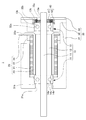
図1は本発明に係る実施形態のモータ1のシャフト11に沿った断面図である。
図1に示すように、モータ1は、ロータ10と、ステータ20と、ケーシング30と、弾性部材40と、を含んでいる。
FIG. 1 is a sectional view taken along a
As shown in FIG. 1, the
(ロータ)
ロータ10は、シャフト11と、シャフト11の外側に配置され、シャフト11の外周面に固定されたマグネット12を含んでいる。
(Rotor)
The
シャフト11へのマグネット12の固定方法は、例えば、圧入固定や接着固定等でよく、特に限定されるものではない。
また、シャフト11をインサート部材としてインサート成形でシャフト11上に、直接、マグネット12を成形するようにしてもよい。
The method of fixing the
Alternatively, the
なお、本実施形態では、シャフト11の外周面に、直接、マグネット12を固定しているが、シャフト11の外周面にロータヨークを固定し、そのロータヨークの外周面にマグネット12を固定するようにしてマグネット12がシャフト11の外側に配置されているものであってもよい。
In this embodiment, the
さらに、ロータ10は、シャフト11の軸方向における一端側(図右側)に設けられた第1転がり軸受13と、シャフト11の軸方向における他端側(図左側)に設けられた第2転がり軸受14と、を含んでいる。
Further, the
第1転がり軸受13は、シャフト11の外周面側に位置し、シャフト11の外周面に固定された第1内輪13aと、第1内輪13aの径方向外側に位置する第1外輪13bと、第1内輪13aと第1外輪13bとの間に介在し、第1内輪13aと第1外輪13bを相互に回転可能に架橋する第1ボール13cと、を備えている。
The first rolling
なお、シャフト11の外周面への第1内輪13aの固定は、特に限定されるものではなく、シャフト11の外周面に、直接、固定する場合には、例えば、圧入固定や接着固定を用いればよく、シャフト11の外周面に間接的に固定する場合には、第1内輪13aとシャフト11の外周面との間に隙間を設け、その隙間に圧入部材を挿入するようにすればよい。
The fixing of the first
第2転がり軸受14は、シャフト11の外周面側に位置し、シャフト11の外周面に固定された第2内輪14aと、第2内輪14aの径方向外側に位置する第2外輪14bと、第2内輪14aと第2外輪14bとの間に介在し、第2内輪14aと第2外輪14bを相互に回転可能に架橋する第2ボール14cと、を備えている。
The second rolling
なお、シャフト11の外周面への第2内輪14aの固定も、第1内輪13aと同様に、特に限定されるものではなく、シャフト11の外周面に、直接、固定する場合には、例えば、圧入固定や接着固定を用いればよく、シャフト11の外周面に間接的に固定する場合には、第2内輪14aとシャフト11の外周面との間に隙間を設け、その隙間に圧入部材を挿入するようにすればよい。
The second
(ステータ)
ステータ20は、電磁鋼板が積層された円筒状のステータコア21と、ステータコア21の内周面及び両端面を覆うように設けられたインシュレータ22と、インシュレータ22を介してステータコア21と絶縁されるようにステータコア21の内側に設けられたコイル23と、を含んでいる。
(Stator)
The
また、ステータ20は、ステータコア21の一端側(図右側)にインシュレータ22を介して一体化され、インシュレータ22によってステータコア21と絶縁状態に保たれている給電端子24を含んでおり、この給電端子24には、コイル23の端部23aが接続されている。
The
したがって、給電端子24に電力を供給すると、コイル23に電流が流れ、ロータ10を回転させることができるようになっている。
Accordingly, when electric power is supplied to the
(ケーシング)
ケーシング30は、一端側(図右側)が開放され、他端側(図左側)が有底状とされたケーシング本体31と、ケーシング本体31の一端側(図右側)に設けられるケーシング端面部32と、ケーシング端面部32の一端側(図右側)に設けられるケーシングキャップ33と、を含んでいる。
(casing)
The
ケーシング本体31は、ステータ20、ステータ20と離間してステータ20内に配置されるマグネット12を含むロータ10の一部を収容する円筒部と、円筒部の他端側(図左側)に一体に設けられ、シャフト11の他端側(図左側)を導出する貫通孔31aが形成された底部を有している。
なお、ケーシング本体31の円筒部は、一端側(図右側)の一部に給電端子24を外部に導出するための切り欠き部が形成されており、この切り欠き部には、給電端子24を収容して外部コネクタ(図示せず)との接続を行うためのコネクタ部材(図示せず)が配置される。
The casing
The cylindrical portion of the
そして、この貫通孔31aの一端側(図右側)を、例えば、第2転がり軸受14の第2外輪14bが圧入できる直径に拡径することで、ケーシング本体31の底部が第2外輪14bを圧入固定の状態で収容する第2外輪収容部31bを有するようになっている。
The bottom end of the
ただし、この第2外輪収容部31bの直径は、必ずしも第2外輪14bを圧入固定できる直径とする必要はなく、例えば、第2外輪14bを隙間嵌めで収容できる程度の直径として、第2外輪14bの外周面と第2外輪収容部31bの内周面との間を接着剤で固定するようにしてもよい。
However, the diameter of the second outer
なお、第2外輪14bは、一端側(図左側)の一部がステータ20のインシュレータ22に挿入され、固定されているため、シャフト11とともに回転する第2内輪14aによって連れ回りが発生し難い状態になっている。
このため、第2外輪14bは、第2外輪収容部31bに隙間嵌めの状態で収容されていてもよい。
Since the second outer ring 14b is partially inserted into and fixed to the
For this reason, the 2nd outer ring | wheel 14b may be accommodated in the 2nd outer ring |
ケーシング端面部32には、第1転がり軸受13を収容するとともにシャフト11の一端側(図右側)を導出する貫通孔32aが形成されている。
この貫通孔32aの他端側(図左側)の直径が小さい部分は第1転がり軸受13の第1外輪13bが隙間嵌めの状態で収容できる直径とされており、貫通孔32aの一端側(図右側)は、弾性部材40が収容できる直径に拡径されることで弾性部材収容部32bが形成されている。
The casing
The small diameter portion on the other end side (the left side in the figure) of the through
このようにして、第1転がり軸受13及び第2転がり軸受14がケーシング30に収容されるようになっている。
In this way, the first rolling bearing 13 and the second rolling bearing 14 are accommodated in the
ケーシングキャップ33には、シャフト11の一端側(図左側)を導出する貫通孔33aが形成されている。
そして、この貫通孔33aを弾性部材40の外径よりも小さく形成することでケーシングキャップ33が弾性部材40の一端側(図右側)を受けることができるようにされている。
The
The
なお、図示を省略しているが、ケーシング本体31の一端側(図右側)の端面には、図示しないネジを螺合固定するネジ固定穴が形成されており、そのネジ固定穴に対応するケーシング端面部32及びケーシングキャップ33の位置には、図示しないネジを通す図示しないネジ孔が形成されている。
Although not shown, a screw fixing hole for screwing and fixing a screw (not shown) is formed on the end surface of one end side (right side of the figure) of the casing
したがって、図示しないネジを用いてケーシング本体31に対してケーシング端面部32及びケーシングキャップ33が共締めによって固定できるようになっている。
Therefore, the casing
(弾性部材)
弾性部材40は、第1転がり軸受13及び第2転がり軸受14に予圧を付与するための部材であり、本実施形態では、弾性部材40は、第1転がり軸受13のシャフト11の軸方向における一端側(図右側)に配置されている。
弾性部材40は、材料として、例えば、ばね鋼、ピアノ線などが用いられるが、以下に記載する機能を満足するものであれば、材料は特に限定されない。
(Elastic member)
The
As the material of the
そして、弾性部材40は、第1転がり軸受13の第1外輪13bをシャフト11の軸方向における他端側(図左側)に付勢する付勢力を発生する本体部41と、本体部41の他端側(図左側)に設けられ、第1外輪13bの外周面を挟持する挟持部42と、を備えている。
The
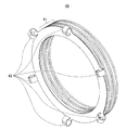
図2は、弾性部材40の他端側を見るようにした斜視図である。
図2に示すように、弾性部材40の本体部41は、波状にうねらせた板材が螺旋状に巻かれた構造をしており、本体部41は、いわゆるコイルドウェーブスプリングで構成されている。
本体部41をコイルドウェーブスプリングで構成することにより、モータ1の軸方向の全高を抑制しつつ、荷重変化のなだらかな適切な付勢力を与えることが可能である。
FIG. 2 is a perspective view in which the other end side of the
As shown in FIG. 2, the
By configuring the
そして、本体部41の一端側(図左側)には、本体部41から延出するように形成された板状部を、本体部41の外側から内側にロールさせるようにすることで弾性力を持たせた複数(本例では6個)の挟持体が図示しない第1外輪13bの周方向に均等間隔で設けられるように形成されることで挟持部42が構成されている。
Then, on one end side (the left side in the figure) of the
また、本実施形態では、本体部41の一部を加工することで挟持体を構成しているが、別部品で作製しておいた挟持体を本体部41に、例えば、溶接、接着、圧接及びカシメ等といった接合手段で接合することで、本体部41に挟持部42を形成するようにしてもよい。
Further, in this embodiment, the sandwiched body is configured by processing a part of the
このため、第1転がり軸受13に、この挟持部42側を向けた状態で弾性部材40を第1転がり軸受13に当接させるように第1転がり軸受13に対して押し込んでいくと、挟持部42を構成する複数の挟持体が外側に拡がるように弾性変形し、挟持体が第1転がり軸受13の第1外輪13bの外周面に当接する状態となるが、挟持体自体は元の状態に戻ろうとするため、この複数の挟持体からなる挟持部42によって第1外輪13bが挟持されることになる。
For this reason, when the
そして、このように挟持部42で第1外輪13bが挟持されていると、シャフト11とともに回転する第1内輪13aによって第1外輪13bに回転方向の力が作用したときに、第1外輪13bと弾性部材40との間で滑りが発生することが抑制される。
And when the 1st outer ring |
一方、図1に示すように、弾性部材40の一端側(図右側)は、ケーシングキャップ33に当接しており、ケーシングキャップ33の表面は、一般に平滑度が極めて高くされている転がり軸受の外輪の端面に比べ、抵抗が大きいため、上述のような回転方向の力が弾性部材40に加わったとしてもケーシングキャップ33と弾性部材40の間で滑りが発生することが少ない。
このため、第1内輪13aの回転によって、第1外輪13bが連れ回ることが抑制される。
On the other hand, as shown in FIG. 1, one end side (right side in the figure) of the
For this reason, it is suppressed that the 1st outer ring |
本発明においては、挟持部42は、弾性部材40の本体部41が一体として構成されているため、挟持部42は、本体部41が軸方向へ伸縮するときに連動して移動するため、挟持部42が本体部41に対して軸方向に対する負荷になることはない。
In the present invention, since the sandwiching
また、軸方向への付勢力の発生と第1外輪13bの連れ回りの抑制の2つの機能を弾性部材40という一つの構成部材で可能となるため、部品点数が増えることが無く、生産性に優れ、コスト抑制にも寄与する。
In addition, since the two functions of generating the urging force in the axial direction and suppressing the accompanying rotation of the first
なお、本実施形態で示した、挟持部42を構成する挟持体の形状は、あくまで一例であって、本実施形態で言えば、挟持体は、第1内輪13aの回転により第1外輪13bが連れ回る現象が抑制されるように、第1外輪13bを挟持する機能を有するものであればよく、特に形状は限定されない。また、挟持体は、求められる挟持力に見合った形状に調整することができる。
In addition, the shape of the clamping body which comprises the clamping
また、挟持体の数は特に限定されるものではなく、適宜設ける数を変更してよい。例えば、モータの使用される回転速度に応じて挟持体の数を調整することにより、使用条件に見合った適切な連れ回り抑制機能を持たせることができる。 Further, the number of the sandwiching bodies is not particularly limited, and the number provided may be changed as appropriate. For example, by adjusting the number of the sandwiching bodies according to the rotational speed at which the motor is used, it is possible to provide an appropriate follow-up suppression function that meets the usage conditions.
ところで、ロータ10を高速回転させることが求められるモータ1の場合、その回転速度の増加に伴って、第1外輪13bにかかる回転力も増加することになり、そのような場合、ケーシングキャップ33と弾性部材40との間でも滑りが発生するおそれがある。
By the way, in the case of the
そこで、ケーシング30に、弾性部材40がシャフト11の周方向に回転するのを規制する規制部を設けるようにすることが好適であり、以下では、ケーシング30に設ける規制部の具体的な一例について説明する。
Therefore, it is preferable to provide the
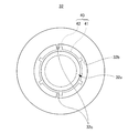
図3は、ケーシング端面部32の弾性部材40を収容する弾性部材収容部32b側が見える一端側から見た平面図である。
なお、図3では、弾性部材収容部32bに弾性部材40が収容されている状態がわかるように仮想的に点線で弾性部材40を併せて記載している。
FIG. 3 is a plan view seen from one end side where the elastic member
In FIG. 3, the
図3に示すように、弾性部材収容部32bの内周面には、内周面から内側に突出するように形成された挟持部42の挟持体に当接して、弾性部材40がシャフト11の周方向に回転するのを規制する規制部32cを設けるようにしている。
As shown in FIG. 3, the
本実施形態では、2つの規制部32cを設けるようにし、1つの規制部32cは弾性部材40が反時計回りに回転しようとするときに挟持部42の挟持体に接触する側に設け、もう一つの規制部32cは弾性部材40が時計回りに回転しようとしたときに挟持部42の挟持体に接触する側に設けている。
In the present embodiment, two restricting
このため弾性部材40は、反時計回り方向及び時計回り方向のどちら側に回ろうとしても規制部32cによって回転が規制される。
したがって、上述したように、ロータ10を高速回転させ、強い回転方向の力が弾性部材40に加わったとしても、弾性部材40が回転することを確実に抑制することができる。
なお、規制部32cの数は特に限定されるものではなく、1つでも3つ以上であってもよい。
For this reason, rotation of the
Therefore, as described above, even when the
In addition, the number of the
規制部32cの数が1つの場合には、弾性部材40が回転方向に動く可能性があるものの、通常、ロータ10は逆回転させるような制御が行われるまでは、同方向に回転し続けるため、弾性部材40が、一旦、規制部32cに当接して動かなくなれば、それ以上動くことが規制されることになり、弾性部材40自体が回転方向に動く頻度が十分に低いことを考えれば、規制部32cの数が1つであっても十分であるケースは多くある。
When the number of the restricting
一方、図3に示す規制部32cは、あくまでも一例であり、別の構成の規制部を設けるようにしてもよい。
図3では、弾性部材収容部32bの内周面から内側に突出するようにして規制部32cが構成されているが、例えば、弾性部材収容部32bの内径を弾性部材40の本体部41の外径より少しだけ大きな内径としておき、弾性部材40の挟持部42を構成する挟持体を位置させる部分に、その挟持体を収容する溝が弾性部材収容部32bの内周面に形成されているような態様であってもよい。
On the other hand, the
In FIG. 3, the restricting
このような溝からなる規制部の場合でも、弾性部材40が回転しようとするときには、その溝の側面が挟持部42の挟持体に当接することになるので、上述した規制部32cと同様に、弾性部材40の回転を規制することが可能である。
Even in the case of a restricting portion made of such a groove, when the
以上、本発明を実施形態に基づき説明したが、本発明は実施形態に限定されるものではない。
上記実施形態では、弾性部材40の本体部41が、波状にうねらせた板材が螺旋状に巻かれた構造とすることでコイル構造とした、いわゆるコイルドウェーブスプリングのような構成のものである場合を示したが、このようなコイル構造を有することに限定されるものではない。
例えば、弾性部材40の本体部41は、ワッシャーを波状にうねらせた、いわゆるウェーブワッシャーのような構造であってもよい。
As mentioned above, although this invention was demonstrated based on embodiment, this invention is not limited to embodiment.
In the said embodiment, the main-
For example, the
また、上記実施形態では、ケーシング本体31は、一端側が開放され、他端側が有底状である形状のものとしたが、ケーシング本体31を両端に開放した円筒状のものとし、ケーシング本体31の底部に当たる部分を別部品で構成して円筒状のケーシング本体31の他端側にネジ等で取り付けるようにしてもよい。
In the above embodiment, the
さらに、ケーシング本体31を両端に開放した円筒状のものとして、ケーシング本体31の他端側に一端側と同様にケーシング端面部とケーシングキャップを設けるような構成としてもよい。
Furthermore, it is good also as a structure which provides a casing end surface part and a casing cap like the one end side at the other end side of the casing
加えて、上記実施形態では、弾性部材40の挟持部42が複数の挟持体を用いて構成されるようにした場合について示したが、例えば、第1外輪13bの外周面の半周以上の範囲を挟持するような1つの挟持体で挟持部42を構成するようにしてもよい。
In addition, in the said embodiment, although it showed about the case where the clamping
また、モータ1に求められるロータ10の回転速度によっては、弾性部材40の回転を規制する規制部32cを設けなくても、ケーシングキャップ33と弾性部材40との間の滑り抵抗を高めるだけで十分な場合もあり、そのためにケーシングキャップ33の弾性部材40を受ける面にサンドブラスト等で粗面化処理を行い、表面粗度を大きくしてケーシングキャップ33と弾性部材40との間の滑り抵抗を高めるようにしてもよいし、ケーシングキャップ33を滑り抵抗が発生しやすい樹脂等の材質で形成するようにしてケーシングキャップ33と弾性部材40との間の滑り抵抗を高めるようにしてもよい。
Further, depending on the rotational speed of the
さらに、上記実施形態では、ケーシング端面部32の弾性部材収容部32bの内周面に、弾性部材40が接触していない状態の場合を示したが、弾性部材40の外周を弾性部材収容部32bの内周面に接触させるようにして、弾性部材40の保持状態の安定性を高めるようにしてもよい。
ただし、弾性部材40は、第1転がり軸受13の第1外輪13bに対して、シャフト11の軸方向に沿った付勢力を付与するためのものであるため、弾性部材収容部32bの内周面に弾性部材40の外周を接触させる場合には、この弾性部材40の伸縮にあまり影響がないようにするのがよい。
Furthermore, in the said embodiment, although the case where the
However, since the
このように、本発明は、具体的な実施形態に限定されるものではなく、本発明の要旨を逸脱しない範囲で種々変更が可能であり、そのことは当業者にとって特許請求の範囲の記載から明らかである。 As described above, the present invention is not limited to the specific embodiments, and various modifications can be made without departing from the gist of the present invention. it is obvious.
1…モータ、10…ロータ、11…シャフト、12…マグネット、13…第1転がり軸受、13a…第1内輪、13b…第1外輪、13c…第1ボール、14…第2転がり軸受、14a…第2内輪、14b…第2外輪、14c…第2ボール、20…ステータ、21…ステータコア、22…インシュレータ、23…コイル、23a…端部、24…給電端子、30…ケーシング、31…ケーシング本体、31a…貫通孔、31b…第2外輪収容部、32…ケーシング端面部、32a…貫通孔、32b…弾性部材収容部、32c…規制部、33…ケーシングキャップ、33a…貫通孔、40…弾性部材、41…本体部、42…挟持部
DESCRIPTION OF
Claims (5)
前記シャフトの軸方向における一端側に設けられ、前記シャフトの外周面側に位置する第1内輪及び前記第1内輪の径方向外側に位置する第1外輪を有する第1転がり軸受と、
前記シャフトの軸方向における他端側に設けられ、前記シャフトの外周面側に位置する第2内輪及び前記第2内輪の径方向外側に位置する第2外輪を有する第2転がり軸受と、
前記第1転がり軸受及び前記第2転がり軸受を収容するケーシングと、
前記第1転がり軸受の前記シャフトの軸方向における一端側に配置され、前記第1転がり軸受及び前記第2転がり軸受に予圧を付与する弾性部材と、を含み、
前記第1転がり軸受は、前記第1外輪が前記ケーシングに隙間嵌めされており、
前記弾性部材は、
前記第1外輪を前記シャフトの軸方向における他端側に付勢する付勢力を発生する本体部と、
前記第1外輪を挟持する挟持部と、を備えるモータ。 A shaft,
A first rolling bearing provided on one end side in the axial direction of the shaft and having a first inner ring located on the outer peripheral surface side of the shaft and a first outer ring located on the radially outer side of the first inner ring;
A second rolling bearing provided on the other end side in the axial direction of the shaft, and having a second inner ring located on the outer peripheral surface side of the shaft and a second outer ring located radially outside the second inner ring;
A casing for housing the first rolling bearing and the second rolling bearing;
An elastic member disposed on one end side in the axial direction of the shaft of the first rolling bearing, and applying a preload to the first rolling bearing and the second rolling bearing,
In the first rolling bearing, the first outer ring is gap-fitted in the casing,
The elastic member is
A main body that generates a biasing force that biases the first outer ring toward the other end in the axial direction of the shaft;
And a clamping unit that clamps the first outer ring.
Priority Applications (1)
| Application Number | Priority Date | Filing Date | Title |
|---|---|---|---|
| JP2016080046A JP6437950B2 (en) | 2016-04-13 | 2016-04-13 | motor |
Applications Claiming Priority (1)
| Application Number | Priority Date | Filing Date | Title |
|---|---|---|---|
| JP2016080046A JP6437950B2 (en) | 2016-04-13 | 2016-04-13 | motor |
Publications (2)
| Publication Number | Publication Date |
|---|---|
| JP2017190825A true JP2017190825A (en) | 2017-10-19 |
| JP6437950B2 JP6437950B2 (en) | 2018-12-12 |
Family
ID=60084631
Family Applications (1)
| Application Number | Title | Priority Date | Filing Date |
|---|---|---|---|
| JP2016080046A Active JP6437950B2 (en) | 2016-04-13 | 2016-04-13 | motor |
Country Status (1)
| Country | Link |
|---|---|
| JP (1) | JP6437950B2 (en) |
Cited By (3)
| Publication number | Priority date | Publication date | Assignee | Title |
|---|---|---|---|---|
| JP2021167669A (en) * | 2020-04-09 | 2021-10-21 | アクティエボラゲット・エスコーエッフ | Bearing unit and manufacturing method of the same |
| KR20220036396A (en) * | 2020-09-14 | 2022-03-23 | 현대자동차주식회사 | Structure for preventing electric corrosion and improving nvh of driving motor |
| US11353061B1 (en) | 2020-12-14 | 2022-06-07 | Schaeffler Technologies AG & Co. KG | Preloaded shaft assembly |
Citations (6)
| Publication number | Priority date | Publication date | Assignee | Title |
|---|---|---|---|---|
| JPH0182653U (en) * | 1987-11-18 | 1989-06-01 | ||
| JPH08149741A (en) * | 1994-11-14 | 1996-06-07 | Matsushita Electric Ind Co Ltd | Bearing device for electric motor |
| JPH0946954A (en) * | 1995-07-28 | 1997-02-14 | Tamagawa Seiki Co Ltd | Motor preload adjustment structure |
| JP2000213447A (en) * | 1999-01-25 | 2000-08-02 | Kawasaki Heavy Ind Ltd | Piston motor |
| JP2008175337A (en) * | 2007-01-22 | 2008-07-31 | Matsushita Electric Ind Co Ltd | Bearing structure |
| JP2009192035A (en) * | 2008-02-18 | 2009-08-27 | Showa Hatsujo Seisakusho:Kk | Spring characteristic adjusting method for compression type coil spring and spring characteristic adjusting type compression biasing body |
-
2016
- 2016-04-13 JP JP2016080046A patent/JP6437950B2/en active Active
Patent Citations (6)
| Publication number | Priority date | Publication date | Assignee | Title |
|---|---|---|---|---|
| JPH0182653U (en) * | 1987-11-18 | 1989-06-01 | ||
| JPH08149741A (en) * | 1994-11-14 | 1996-06-07 | Matsushita Electric Ind Co Ltd | Bearing device for electric motor |
| JPH0946954A (en) * | 1995-07-28 | 1997-02-14 | Tamagawa Seiki Co Ltd | Motor preload adjustment structure |
| JP2000213447A (en) * | 1999-01-25 | 2000-08-02 | Kawasaki Heavy Ind Ltd | Piston motor |
| JP2008175337A (en) * | 2007-01-22 | 2008-07-31 | Matsushita Electric Ind Co Ltd | Bearing structure |
| JP2009192035A (en) * | 2008-02-18 | 2009-08-27 | Showa Hatsujo Seisakusho:Kk | Spring characteristic adjusting method for compression type coil spring and spring characteristic adjusting type compression biasing body |
Cited By (5)
| Publication number | Priority date | Publication date | Assignee | Title |
|---|---|---|---|---|
| JP2021167669A (en) * | 2020-04-09 | 2021-10-21 | アクティエボラゲット・エスコーエッフ | Bearing unit and manufacturing method of the same |
| KR20220036396A (en) * | 2020-09-14 | 2022-03-23 | 현대자동차주식회사 | Structure for preventing electric corrosion and improving nvh of driving motor |
| KR102729821B1 (en) | 2020-09-14 | 2024-11-15 | 현대자동차주식회사 | Structure for preventing electric corrosion and improving nvh of driving motor |
| US11353061B1 (en) | 2020-12-14 | 2022-06-07 | Schaeffler Technologies AG & Co. KG | Preloaded shaft assembly |
| WO2022132365A1 (en) * | 2020-12-14 | 2022-06-23 | Schaeffler Technologies AG & Co. KG | Preloaded shaft assembly |
Also Published As
| Publication number | Publication date |
|---|---|
| JP6437950B2 (en) | 2018-12-12 |
Similar Documents
| Publication | Publication Date | Title |
|---|---|---|
| US10840778B2 (en) | Shaft grounding ring and dissipation body for a shaft grounding ring | |
| JP6437950B2 (en) | motor | |
| US20160049837A1 (en) | Electric motor comprising an internal rotor and an external stator | |
| JP2016086555A (en) | Electrical equipment | |
| CN102261297A (en) | Starter Motor In A Starter For A Combustion Engine | |
| JP5911577B2 (en) | Rotating electric machine | |
| JP2020005442A (en) | Rotating electric machine rotor | |
| JP5138489B2 (en) | Resolver rotor fixing structure and brushless motor | |
| WO2019155541A1 (en) | Control device-integrated rotary electric machine | |
| JP2017020624A (en) | Ball screw device | |
| JP5495045B2 (en) | Rotating electrical machine rotor | |
| JP6504908B2 (en) | Motor bearing structure | |
| JPWO2018235184A1 (en) | Electric motor and method of assembling electric motor | |
| JP6032178B2 (en) | Induction motor rotor | |
| JP2018121440A (en) | Assembly structure of end plate | |
| JP6676211B2 (en) | Motor generator | |
| JP7092477B2 (en) | Rotating electric stator | |
| JP2016178815A (en) | Motor bearing structure and bearing mounting method | |
| JP2011244595A (en) | Motor | |
| JP2018121441A (en) | Assembly structure of end plate | |
| JP6354155B2 (en) | Electric motor | |
| JP2010142095A (en) | Electric motor | |
| KR20220071552A (en) | Motor | |
| JP2017153295A (en) | Rotating electric machine | |
| JP2025142494A (en) | rotor |
Legal Events
| Date | Code | Title | Description |
|---|---|---|---|
| A621 | Written request for application examination |
Free format text: JAPANESE INTERMEDIATE CODE: A621 Effective date: 20170807 |
|
| A977 | Report on retrieval |
Free format text: JAPANESE INTERMEDIATE CODE: A971007 Effective date: 20180509 |
|
| A131 | Notification of reasons for refusal |
Free format text: JAPANESE INTERMEDIATE CODE: A131 Effective date: 20180515 |
|
| A521 | Request for written amendment filed |
Free format text: JAPANESE INTERMEDIATE CODE: A523 Effective date: 20180613 |
|
| A131 | Notification of reasons for refusal |
Free format text: JAPANESE INTERMEDIATE CODE: A131 Effective date: 20180828 |
|
| A521 | Request for written amendment filed |
Free format text: JAPANESE INTERMEDIATE CODE: A523 Effective date: 20180927 |
|
| TRDD | Decision of grant or rejection written | ||
| A01 | Written decision to grant a patent or to grant a registration (utility model) |
Free format text: JAPANESE INTERMEDIATE CODE: A01 Effective date: 20181113 |
|
| A61 | First payment of annual fees (during grant procedure) |
Free format text: JAPANESE INTERMEDIATE CODE: A61 Effective date: 20181115 |
|
| R150 | Certificate of patent or registration of utility model |
Ref document number: 6437950 Country of ref document: JP Free format text: JAPANESE INTERMEDIATE CODE: R150 |