JP2017190821A - Tapered roller bearing - Google Patents
Tapered roller bearing Download PDFInfo
- Publication number
- JP2017190821A JP2017190821A JP2016080001A JP2016080001A JP2017190821A JP 2017190821 A JP2017190821 A JP 2017190821A JP 2016080001 A JP2016080001 A JP 2016080001A JP 2016080001 A JP2016080001 A JP 2016080001A JP 2017190821 A JP2017190821 A JP 2017190821A
- Authority
- JP
- Japan
- Prior art keywords
- outer ring
- tapered roller
- roller bearing
- peripheral surface
- lubricating oil
- Prior art date
- Legal status (The legal status is an assumption and is not a legal conclusion. Google has not performed a legal analysis and makes no representation as to the accuracy of the status listed.)
- Granted
Links
Images
Landscapes
- Sealing Of Bearings (AREA)
- Rolling Contact Bearings (AREA)
Abstract
【課題】外輪のうち潤滑油保持部材と嵌まり合う部分を研磨加工することなく潤滑油保持部材を外輪に取り付けた円すいころ軸受を提供する。【解決手段】円すいころ軸受1は、外輪10と、内輪20と、複数の円すいころ30と、潤滑油保持部材50と、を備える。潤滑油保持部材50の筒状部52は、内周面64に、径方向内方に向かって突出して形成された凸部65を有し、薄肉部14は、外周面15に、凸部65を収容可能に形成された凹部16を有する。【選択図】図3Provided is a tapered roller bearing in which a lubricating oil holding member is attached to an outer ring without polishing a portion of the outer ring that fits with the lubricating oil holding member. A tapered roller bearing includes an outer ring, an inner ring, a plurality of tapered rollers, and a lubricating oil holding member. The cylindrical portion 52 of the lubricating oil holding member 50 has a convex portion 65 formed on the inner peripheral surface 64 so as to protrude radially inward, and the thin portion 14 has a convex portion 65 on the outer peripheral surface 15. Has a concave portion 16 formed so as to be capable of accommodating therein. [Selection diagram] FIG.
Description
本発明は、円すいころ軸受に関し、特に、円すいころが転動する空間に潤滑油を貯留する円すいころ軸受に関する。 The present invention relates to a tapered roller bearing, and more particularly to a tapered roller bearing that stores lubricating oil in a space in which the tapered roller rolls.
円すいころ軸受は、外輪、内輪、複数の円すいころ、及び保持器を備える。円すいころは、円すいころが転動する方向の軸が、円すいころ軸受の軸心に対して傾斜するように配置されている。円すいころの大径の底面(以下、大端面とも称する。)は、小径の底面(以下、小端面とも称する。)よりも、軸受の径方向外方に配置されている。 The tapered roller bearing includes an outer ring, an inner ring, a plurality of tapered rollers, and a cage. The tapered roller is arranged so that the axis in the direction in which the tapered roller rolls is inclined with respect to the axis of the tapered roller bearing. The large diameter bottom surface (hereinafter also referred to as a large end surface) of the tapered roller is disposed radially outward of the bearing from the small diameter bottom surface (hereinafter also referred to as a small end surface).
円すいころ軸受の特性としては、円すいころの大端面と、内輪のうち円すいころの大端面と接触する面(以下、大つば面とも称する。)との焼き付きに対する耐性を向上させること、及び円すいころ軸受の保持器のポケット面の摩耗を抑制することが求められる。このような円すいころ軸受として、外輪に潤滑油保持部材を取り付けて、潤滑油保持部材と外輪の間の空間に潤滑油を貯留する円すいころ軸受が知られている(例えば、特許文献1)。 Tapered roller bearings are characterized by improving resistance to seizure between the large end surface of the tapered roller and the surface of the inner ring that contacts the large end surface of the tapered roller (hereinafter also referred to as the large collar surface), and the tapered roller. It is required to suppress wear on the pocket surface of the bearing cage. As such a tapered roller bearing, a tapered roller bearing in which a lubricating oil holding member is attached to an outer ring and the lubricating oil is stored in a space between the lubricating oil holding member and the outer ring is known (for example, Patent Document 1).
ところで、特許文献1の円すいころ軸受は、外輪の一部の肉厚を薄くして薄肉部分を形成し、薄肉部分の外周に潤滑油保持部材を圧入することにより、外輪に潤滑油保持部材を固定している。この場合、外輪の外周面の径の寸法と潤滑油保持部材の内径の寸法とに高い精度が要求される。そのため、外輪のうち潤滑油保持部材を圧入する部分に対して、切削加工に加え、研磨加工を行う必要がある。これにより、外輪の製造工程が煩雑になる。特に、潤滑油保持部材は外輪のうち薄肉部分に圧入されるので、薄肉部分とそれ以外の部分との段差付近における研磨作業が外輪の歩留まりの低下の原因となる。
By the way, in the tapered roller bearing of
上記の課題を鑑み、本発明は、外輪のうち潤滑油保持部材と嵌まり合う部分を研磨加工することなく潤滑油保持部材を外輪に取り付け可能な円すいころ軸受を提供することを目的とする。 In view of the above problems, an object of the present invention is to provide a tapered roller bearing capable of attaching a lubricating oil holding member to the outer ring without polishing a portion of the outer ring that fits with the lubricating oil holding member.
上記の課題を解決する本発明の円すいころ軸受は、内周面に第1の軌道面を有する外輪と、外周面に第2の軌道面を有し、外輪と同軸上に配置された内輪と、第1の軌道面及び第2の軌道面の間の空間に配置された複数の円すいころと、外輪と一体に固定された潤滑油保持部材と、を備える。外輪は、外周面に設けられた環状の段差面によって軸方向一方側の端部に環状の薄肉部が形成され、軸方向の他方側の端部がハウジングに嵌め込まれる。潤滑油保持部材は、軸方向に延びる円筒状に形成され、軸方向他方側の端面が外輪の段差面に軸方向に対向し且つ薄肉部の外周面を覆うように配置された筒状部と、径方向に延びる円環状に形成され、径方向外方における端部が筒状部の軸方向一方側の端部に接続された環状部と、を含む。筒状部は、内周面に、径方向内方に向かって突出して形成された凸部を有する。薄肉部は、外周面に、凸部を収容可能で潤滑油保持部材の軸方向の移動を規制するように形成された凹部を有する。 The tapered roller bearing of the present invention that solves the above problems includes an outer ring having a first raceway surface on an inner peripheral surface, an inner ring having a second raceway surface on an outer peripheral surface and disposed coaxially with the outer ring. And a plurality of tapered rollers disposed in a space between the first raceway surface and the second raceway surface, and a lubricant holding member fixed integrally with the outer ring. The outer ring is formed with an annular thin portion at one end in the axial direction by an annular step surface provided on the outer peripheral surface, and the other end in the axial direction is fitted into the housing. The lubricating oil retaining member is formed in a cylindrical shape extending in the axial direction, and has a cylindrical portion disposed so that the end surface on the other side in the axial direction faces the step surface of the outer ring in the axial direction and covers the outer peripheral surface of the thin portion. And an annular portion formed in an annular shape extending in the radial direction and having an end portion on the radially outer side connected to an end portion on one axial side of the cylindrical portion. The cylindrical portion has a convex portion formed on the inner peripheral surface so as to protrude inward in the radial direction. The thin-walled portion has a concave portion formed on the outer peripheral surface so as to accommodate the convex portion and to restrict the movement of the lubricating oil retaining member in the axial direction.
本発明によれば、外輪のうち潤滑油保持部材と嵌まり合う部分を研磨加工することなく潤滑油保持部材を外輪に取り付け可能な円すいころ軸受が得られる。 According to the present invention, it is possible to obtain a tapered roller bearing capable of attaching the lubricating oil holding member to the outer ring without polishing the portion of the outer ring that fits with the lubricating oil holding member.
本発明の円すいころ軸受は、内周面に第1の軌道面を有する外輪と、外周面に第2の軌道面を有し、外輪と同軸上に配置された内輪と、第1の軌道面及び第2の軌道面の間の空間に配置された複数の円すいころと、外輪と一体に固定された潤滑油保持部材と、を備える。外輪は、外周面に設けられた環状の段差面によって軸方向一方側の端部に環状の薄肉部が形成され、軸方向の他方側の端部がハウジングに嵌め込まれる。潤滑油保持部材は、軸方向に延びる円筒状に形成され、軸方向他方側の端面が外輪の段差面に軸方向に対向し且つ薄肉部の外周面を覆うように配置された筒状部と、径方向に延びる円環状に形成され、径方向外方における端部が筒状部の軸方向一方側の端部に接続された環状部と、を含む。筒状部は、内周面に、径方向内方に向かって突出して形成された凸部を有する。薄肉部は、外周面に、凸部を収容可能で潤滑油保持部材の軸方向の移動を規制するように形成された凹部を有する。 The tapered roller bearing according to the present invention includes an outer ring having a first raceway surface on an inner peripheral surface, an inner ring having a second raceway surface on an outer peripheral surface and disposed coaxially with the outer ring, and a first raceway surface. And a plurality of tapered rollers disposed in a space between the second raceway surfaces, and a lubricant holding member fixed integrally with the outer ring. The outer ring is formed with an annular thin portion at one end in the axial direction by an annular step surface provided on the outer peripheral surface, and the other end in the axial direction is fitted into the housing. The lubricating oil retaining member is formed in a cylindrical shape extending in the axial direction, and has a cylindrical portion disposed so that the end surface on the other side in the axial direction faces the step surface of the outer ring in the axial direction and covers the outer peripheral surface of the thin portion. And an annular portion formed in an annular shape extending in the radial direction and having an end portion on the radially outer side connected to an end portion on one axial side of the cylindrical portion. The cylindrical portion has a convex portion formed on the inner peripheral surface so as to protrude inward in the radial direction. The thin-walled portion has a concave portion formed on the outer peripheral surface so as to accommodate the convex portion and to restrict the movement of the lubricating oil retaining member in the axial direction.
上記の構成によれば、潤滑油保持部材の筒状部の凸部と、外輪の薄肉部の外周面の凹部とが、対応するように形成されているので、筒状部の凸部を薄肉部の凹部に係合させることができる。そのため、筒状部の内周面を薄肉部の外周面に圧入することなく、筒状部が薄肉部の外周面を覆うように潤滑油保持部材を外輪に固定することができる。 According to said structure, since the convex part of the cylindrical part of a lubricating oil holding member and the recessed part of the outer peripheral surface of the thin part of an outer ring | wheel are formed corresponding, the convex part of a cylindrical part is made thin. It can be engaged with the recess of the part. Therefore, the lubricating oil holding member can be fixed to the outer ring so that the cylindrical portion covers the outer peripheral surface of the thin portion without press-fitting the inner peripheral surface of the cylindrical portion into the outer peripheral surface of the thin portion.
筒状部の内周面を薄肉部の外周面に圧入する必要がないので、筒状部の内周面の寸法と薄肉部の外周面の寸法とに高い精度が要求されない。したがって、薄肉部の外周面を研磨する工程が不要となり、外輪の歩留まりを向上させることができる。 Since it is not necessary to press-fit the inner peripheral surface of the cylindrical portion into the outer peripheral surface of the thin portion, high accuracy is not required for the dimensions of the inner peripheral surface of the cylindrical portion and the outer peripheral surface of the thin portion. Therefore, the step of polishing the outer peripheral surface of the thin portion is not required, and the yield of the outer ring can be improved.
本発明の円すいころ軸受は、潤滑油保持部材における軸方向内方の端面から凸部の軸方向内方の端部までの距離が、外輪の段差面から凹部の軸方向内方の端部までの距離以上であることが好ましい。 In the tapered roller bearing of the present invention, the distance from the axially inner end surface of the lubricating oil holding member to the axially inner end of the convex portion is from the step surface of the outer ring to the axially inner end of the concave portion. It is preferable that it is more than this distance.
円すいころ軸受は、外輪のうち薄肉部が形成された端面と反対側の端面において、ハウジングに取り付けられる。上記の構成によれば、潤滑油保持部材における軸方向内方の端面から凸部の軸方向内方の端部までの距離は、外輪の段差面から凹部の軸方向内方の端部までの距離以上であるので、筒状部の凸部の表面と薄肉部の凹部の表面とが軸方向に接触しにくくなる。そのため、円すいころ軸受をハウジングに取り付ける際に潤滑油保持部材に力を加えても、潤滑油保持部材に加えた力が凸部及び凹部を介して外輪に影響するのが抑制される。その一方で、筒状部の軸方向内方の端面が外輪の段差面に軸方向に接触しているので、潤滑油保持部材に加えた力を、筒状部の軸方向内方の端面と外輪の段差面との接触部分を介して効果的に外輪に伝えることができる。つまり、潤滑油保持部材に加えた力を、効果的に、外輪をハウジングに取り付けるための力として用いることができる。 The tapered roller bearing is attached to the housing on the end surface opposite to the end surface where the thin portion is formed in the outer ring. According to the above configuration, the distance from the axially inner end surface of the lubricant holding member to the axially inner end of the convex portion is from the step surface of the outer ring to the axially inner end of the concave portion. Since it is more than the distance, it becomes difficult for the surface of the convex part of the cylindrical part and the surface of the concave part of the thin part to contact in the axial direction. Therefore, even if a force is applied to the lubricating oil holding member when attaching the tapered roller bearing to the housing, the force applied to the lubricating oil holding member is suppressed from affecting the outer ring via the convex portion and the concave portion. On the other hand, since the axially inner end surface of the cylindrical portion is in axial contact with the step surface of the outer ring, the force applied to the lubricating oil retaining member is applied to the axially inner end surface of the cylindrical portion. It can be effectively transmitted to the outer ring through the contact portion with the step surface of the outer ring. That is, the force applied to the lubricating oil holding member can be effectively used as a force for attaching the outer ring to the housing.
本発明の円すいころ軸受は、外輪の段差面が、軸方向に垂直な面を有し、筒状部の軸方向内方の端面が、軸方向に垂直な面を有することが好ましい。 In the tapered roller bearing of the present invention, it is preferable that the step surface of the outer ring has a surface perpendicular to the axial direction, and the axially inner end surface of the cylindrical portion has a surface perpendicular to the axial direction.
上記の構成によれば、筒状部の軸方向内方の端面と外輪の段差面が軸方向に垂直な面を介して接触しているので、円すいころ軸受をハウジングに取り付ける際、潤滑油保持部材に加えた力を効率的に外輪に伝えることができる。 According to the above configuration, the axially inner end surface of the cylindrical portion and the step surface of the outer ring are in contact with each other via a surface perpendicular to the axial direction. Therefore, when attaching the tapered roller bearing to the housing, the lubricating oil is retained. The force applied to the member can be efficiently transmitted to the outer ring.
本発明の円すいころ軸受の凹部は、薄肉部の外周面の全周に亘って溝状に形成されていることが好ましい。 The concave portion of the tapered roller bearing of the present invention is preferably formed in a groove shape over the entire circumference of the outer peripheral surface of the thin portion.
上記の構成によれば、凹部が薄肉部の全周に亘って溝状に形成されているので、凹部を旋削加工によって容易に形成することができる。また、凹部が全周に亘って形成されているので、外輪に潤滑油保持部材を取り付けるときに、凹部と凸部のアライメントについて考慮することなく凸部を凹部に係合させることができ、外輪に潤滑油保持部材を取り付ける作業が容易になる。 According to said structure, since a recessed part is formed in groove shape over the perimeter of a thin part, a recessed part can be easily formed by turning. In addition, since the concave portion is formed over the entire circumference, when attaching the lubricant holding member to the outer ring, the convex portion can be engaged with the concave portion without considering the alignment of the concave portion and the convex portion. The operation of attaching the lubricant holding member to the cylinder becomes easy.
本発明の円すいころ軸受の凸部は、複数個形成されていると共に、筒状部の内周面に周方向に並び且つ等間隔で配置されていることが好ましい。 It is preferable that a plurality of convex portions of the tapered roller bearing of the present invention are formed and arranged in the circumferential direction at equal intervals on the inner peripheral surface of the cylindrical portion.
上記の構成によれば、筒状部をたとえばディンプル加工等することによって複数の凸部を形成することができるので、凸部を容易に形成することができる。また、複数の凸部が等間隔で配置されているので、外輪に対する筒状部の安定性を良好なものとすることができる。 According to said structure, since a some convex part can be formed by carrying out the dimple process etc. of a cylindrical part, a convex part can be formed easily. In addition, since the plurality of convex portions are arranged at equal intervals, the stability of the cylindrical portion with respect to the outer ring can be improved.
以下、図面を参照しつつ、本発明の好適な実施の形態について詳細に説明する。以下の説明において参照する各図は、説明の便宜上、本発明の実施形態の構成部材のうち、本発明を説明するために必要な主要部材を示したものである。従って、本発明は以下の各図に示されていない任意の構成部材を備え得る。また、以下の各図中の部材の寸法は、実際の寸法および各部材の寸法比率等を忠実に表したものではない。 Hereinafter, preferred embodiments of the present invention will be described in detail with reference to the drawings. Each drawing referred to in the following description shows, for convenience of description, main members necessary for explaining the present invention among the constituent members of the embodiment of the present invention. Therefore, the present invention can include arbitrary components not shown in the following drawings. In addition, the dimensions of the members in the following drawings do not faithfully represent actual dimensions, dimensional ratios of the members, or the like.
<実施形態1>
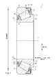
図1は、実施形態1の円すいころ軸受1の断面図である。図1は、円すいころ軸受1の外輪中心軸L1を通る断面図である。円すいころ軸受1は、例えば、自動車等の変速装置の軸を指示する軸受に用いられる。なお、本明細書において、単に「軸方向」というときは、外輪中心軸L1の軸方向を意味することとする。
<
FIG. 1 is a sectional view of a tapered
図1に示すように、円すいころ軸受1は、外輪10,内輪20,複数の円すいころ30、保持器40,及び潤滑油保持部材50を備える。外輪10,内輪20、保持器40及び潤滑油保持部材50は、円すいころ軸受1の外輪中心軸L1と同軸上に設けられた環状の部材である。潤滑油保持部材50は、外輪10に取り付けることで、潤滑油保持部材50と外輪10との間の空間に潤滑油Jを貯留する機能を有する部材である。
As shown in FIG. 1, the tapered
外輪10と内輪20とは、図1に示すように、外輪10の径方向内側に内輪20が嵌まるように配置されている。径方向において外輪10と内輪20とで挟まれた空間には、複数の円すいころ30が配置されている。保持器40は、複数の円すいころ30を保持している。潤滑油保持部材50は、外輪10の軸方向の一方の端部に取り付けられている。
As shown in FIG. 1, the
円すいころ30は、円すい台の形状を有する。円すいころ30のころの中心軸L2は、外輪中心軸L1に対して傾斜している。ころの中心軸L2は、円すいころ30の小径側の底面31(以下、小端面31とも称する。)から大径側の底面32(以下、大端面32とも称する。)に向かうにつれて、外輪中心軸L1から離間している。
The tapered
なお、本明細書の以下の記載において、軸方向のうち、内輪20の背面23側の方向を「一方側」、正面24側の方向を「他方側」とする。円すいころ軸受1の軸方向一方側の端部の構造(たとえば、潤滑油保持部材50など)において、円すいころ軸受1の軸方向外方が一方側に相当する。また、円すいころ軸受1の軸方向内方が他方側に相当する。
In the following description of the present specification, among the axial directions, the direction on the
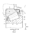
図2は、円すいころ軸受1の一部を拡大した断面図である。
FIG. 2 is an enlarged sectional view of a part of the tapered
外輪10は、内周面に第1の軌道面11を有する。第1の軌道面11は、軸方向他方側から一方側に向かうにつれて外輪中心軸L1との距離が大きくなった、テーパー形状となっている。
The
外輪10の外周面12には、環状の段差面13が周方向に沿って形成されている。段差面13は、外輪中心軸L1に垂直な面である。外輪10のうち、段差面13よりも軸方向一方側は、他方側よりも径方向の厚さが小さい薄肉部14となっている。段差面13及び薄肉部14は、潤滑油保持部材50を外輪に固定するために形成されている。薄肉部14の外周面15は、外輪中心軸L1に対して平行な円筒面である。
An
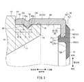
図3は、潤滑油保持部材50及び外輪10の一部を示す断面図である。外輪10の薄肉部14の外周面15には、環状の溝16が形成されている。溝16は、径方向外方に開口している。溝16は、例えば、断面が三角形に形成されている。
FIG. 3 is a cross-sectional view showing a part of the
内輪20は、図2に示すように、外周面に第2の軌道面22を有する。第2の軌道面22は、軸方向他方側から一方側に向かうにつれて外輪中心軸L1との距離が大きくなった、テーパー形状となっている。なお、第2の軌道面22の外輪中心軸L1に対するテーパー角は、第1の軌道面11のテーパー角よりも小さい。
As shown in FIG. 2, the
内輪20の第2の軌道面22よりも軸方向他方側は、径方向の大きさが第2の軌道面22の軸方向他方側の端部よりも大きく形成されており、円すいころ30の小端面31と対向する小つば部25が形成されている。また、内輪20の第2の軌道面22よりも軸方向一方側は、径方向の大きさが第2の軌道面22の軸方向一方側の端部よりも大きく形成されており、円すいころ30の大端面32と対向する大つば部26が形成されている。
The other side of the
図2に示すように、円すいころ30は、第1の軌道面11と第2の軌道面22との間に構成される空間に配置されている。上述のように、複数の円すいころ30のそれぞれは円すい台の形状であり、ころの中心軸L2は、外輪中心軸L1に対して傾斜している。
As shown in FIG. 2, the tapered
保持器40は、図示しないが、軸方向他方側から一方側に向かうにつれて外輪中心軸L1との距離が大きくなるテーパー面を有する円環形状となっている。保持器40のテーパー面には、複数のポケット41が形成されている。テーパー面における複数のポケット41のそれぞれの形状は、円すいころ30の形状に対応する略台形である。保持器40は、金属または樹脂で形成されている。
Although not shown, the
潤滑油保持部材50は、図3に示すように、リング60と、弾性体リップ70とで構成されている。
As shown in FIG. 3, the
リング60は、円筒状のリング本体61と、リング本体61の内周面から径方向内方に突出した環状の爪62と、を含む。リング本体61と爪62とは、一体に形成されている。リング本体61の内径の大きさは、外輪10の薄肉部14の外周面15の外側に嵌め合わせが可能な大きさとなっている。爪62は、リング本体61の軸方向外側に形成されている。リング60は、例えば、ステンレス等の金属で形成されている。
The
リング本体61の軸方向他方側の端面63は、段差面13と略平行に配置された円環状の面である。端面63は、外輪中心軸L1に垂直な面である。また、リング本体61の内周面64は、外輪10の薄肉部14の外周面15と略平行に配置された円筒状の面である。
The
リング本体61には、複数の凸部65が形成されている。複数の凸部65は、内周面64から径方向内方に突出しており、潤滑油保持部材50が外輪10に固定された状態において薄肉部14の外周面15に形成された溝16に嵌め合い可能な位置に形成されている。つまり、複数の凸部65は、周方向に間隔をあけて離間して配置されている。複数の凸部65は、例えば、3〜10個形成されている。
A plurality of
リング本体61の軸方向他方側の端面63から凸部65の軸方向他方側の端部65aまでの距離(図3で「A」で示す長さ)は、外輪10の段差面13から溝16の軸方向他方側の端部16aまでの距離(図3で「B」で示す長さ)よりも大きく設定されている。そのため、リング本体61の端面63が外輪10の段差面13に接した状態においては、凸部65の軸方向他方側の端部65aは、溝16の軸方向他方側の端部16aに接触しない。
The distance (the length indicated by “A” in FIG. 3) from the
複数の凸部65のリング本体61の内周面から径方向内方に突出する高さは、溝16の薄肉部14の外周面15からの凹み深さよりも小さく設定されている。また、溝16の軸方向の幅(図3で「C」で示す、端部16aと溝16の軸方向一方側の端部16bを結ぶ長さ)は、凸部65の軸方向の幅(図3で「D」で示す、端部65aと凸部65の軸方向一方側の端部65bを結ぶ長さ)よりも大きく設定されている。そのため、凸部65が溝16に収容された状態において、凸部65の表面と溝16の内壁との間に隙間が存在することとなる。
The height of the plurality of
複数の凸部65は、例えば、リング本体61の外周面から径方向に内方に向かってディンプル加工することにより形成されている。凸部65がディンプル加工で形成されている場合、リング本体61の外周面のうち凸部65が形成された場所に対応する場所は凹みが形成されている。
The plurality of
弾性体リップ70の形状は、全体として、円環形状である。弾性体リップ70のうち径方向外方を構成する部分は、軸方向の厚さがリング60の爪62の厚さよりも大きい、厚肉部71となっている。また、弾性体リップ70のうち径方向内方を構成する部分は、厚肉部71よりも軸方向の厚さが小さい薄肉部72となっている。弾性体リップ70は、例えば、ニトリルゴム、アクリルゴム等のゴムで形成されている。
The shape of the
弾性体リップ70においては、厚肉部71と薄肉部72が連続して一体に形成されている。つまり、弾性体リップ70の軸方向内側の表面においては、厚肉部71の表面71bが薄肉部72の表面72bよりも軸方向内側に位置づけられている。
In the
厚肉部71には、径方向において外方から内方に向かう溝73が形成されている。溝73は、厚肉部71の全周に亘って形成されている。溝73の大きさは、リング60の爪62をはめ込み可能な大きさに設定されている。溝73に爪62をはめ込むことにより、リング60と弾性体リップ70とが一体に組み合わされ、潤滑油保持部材50を構成している。
なお、リング60と弾性体リップ70とが一体に組み合わされることにより、潤滑油保持部材50の形状は、全体として、円環状の環状部51と、筒状部52とが一体となった形状になっている。環状部51は、リング60の爪62及び弾性体リップ70に相当する。また、筒状部52は、リング本体61に相当する。
In addition, the
図3に示すように、リング60は、リング本体61の内周面64が外輪10の薄肉部14の外周面15を覆い、リング本体61の軸方向他方側の端面63が外輪10の段差面13に対向するように、外輪10の軸方向一方側の端部に嵌め込まれる。このとき、リング60を軸方向から嵌め込む際に凸部65が外周面15にあたり、リング60が弾性変形することで、凸部65が外周面を越えて溝16に収容される。これにより、外輪10と潤滑油保持部材50とが固定される。
As shown in FIG. 3, in the
このとき、複数の凸部65は、溝16に収容される。これにより、潤滑油保持部材50の軸方向の移動が規制され、潤滑油保持部材50が外輪10から抜け落ちることを防止することができる。
At this time, the plurality of
潤滑油保持部材50と外輪10の間に形成される空間には、図1の下部に示すように、潤滑油Jが供給される。潤滑油Jは、円すいころ軸受1の鉛直方向の下方向側の下部に溜まることとなる。潤滑油Jの液面S1の高さは、円すいころ軸受1の最下部における弾性体リップ70の高さとなっている。
Lubricating oil J is supplied to the space formed between the lubricating
円すいころ軸受1の静止状態においては、潤滑油Jは、外輪10の一部、円すいころ30の一部及び保持器40の一部と接触している。円すいころ軸受1が回転することにより、円すいころ軸受1の下部に溜まった潤滑油Jが回転と共に巻き上げられ、第1の軌道面11及び第2の軌道面22等に供給される。そして、供給された潤滑油Jにより、円すいころ30と第1の軌道面11の間や、円すいころ30と第2の軌道面22の間などに発生する摩擦が低減される。
In the stationary state of the tapered
上記の構成の円すいころ軸受1は、図2に示すように、外輪10の外周面がハウジング200に接するようにハウジング200に嵌め込まれる。円すいころ軸受1をハウジング200に嵌め込む作業において、作業者は、外輪10に固定された潤滑油保持部材50の環状部51を押すこととなる。このとき、作業者が環状部51に加えた力は、リング本体61の端面63から外輪10の段差面13に伝達され、外輪10をハウジング200に嵌め込む力として用いられる。
As shown in FIG. 2, the tapered
なお、円すいころ軸受1とハウジング200との間には、図2には図示しないが、例えば、皿ばね等からなるリングが存在していてもよい。
Although not shown in FIG. 2, for example, a ring made of a disc spring or the like may exist between the
(実施形態1の効果)
実施形態1の円すいころ軸受1によれば、リング本体61に形成された複数の凸部65が溝16に収容されることにより、潤滑油保持部材50の軸方向の移動が規制され、潤滑油保持部材50が外輪10から抜け落ちることを防止することができる。そのため、潤滑油保持部材50を外輪10の薄肉部14に締まりばめすることなく、潤滑油保持部材50を外輪10に固定することができる。
(Effect of Embodiment 1)
According to the tapered
潤滑油保持部材を外輪の薄肉部に締まりばめする場合には、潤滑油保持部材の内周の径が外輪の薄肉部の外周の径よりもやや小さくなるように設定する必要があり、潤滑油保持部材の内周面の寸法と薄肉部の外周面の寸法とに高い精度が要求される。しかしながら、本実施形態の円すいころ軸受1によれば、潤滑油保持部材50を外輪10の薄肉部14に締まりばめする必要がないので、リング本体61の内周面の寸法と薄肉部14の外周面の寸法とに高い精度が要求されない。したがって、薄肉部の外周面を研磨する工程が不要となり、外輪10の歩留まりを向上させることができる。
When the lubricating oil retaining member is fitted to the thin part of the outer ring, it is necessary to set the inner diameter of the lubricating oil retaining member to be slightly smaller than the outer diameter of the thin part of the outer ring. High accuracy is required for the dimensions of the inner peripheral surface of the oil retaining member and the outer peripheral surface of the thin wall portion. However, according to the tapered
実施形態1の円すいころ軸受1は、図2に示すように、外輪10のうち軸方向一方側の端面において、ハウジング200に取り付けられる。上記の構成によれば、リング本体61の軸方向他方側の端面63から凸部65の軸方向他方側の端部までの距離(図3で「A」で示す長さ)は、外輪10の段差面13から溝16の軸方向他方側の端部までの距離(図3で「B」で示す長さ)よりも大きく設定されている。そのため、リング本体61の端面63が外輪10の段差面13に接した状態においては、凸部65の軸方向他方側の端部は、溝16の軸方向他方側の端部に接触しない。
As shown in FIG. 2, the tapered
したがって、円すいころ軸受1をハウジング200に取り付けるために潤滑油保持部材50に対して力を加えるとき、潤滑油保持部材50のリング本体61は、リング本体61の凸部65の軸方向他方側の端部が溝16の表面に接触するよりも先に、リング本体61の端面63が外輪10の段差面13に接触することとなる。その結果、潤滑油保持部材50に加えた力を、リング本体61の端面63と外輪10の段差面13との接触部分を介して、効果的に外輪10に伝えることができる。つまり、潤滑油保持部材50に加えた力を、効果的に、外輪10をハウジング200に取り付けるための力として用いることができる。
Therefore, when a force is applied to the lubricating
また、円すいころ軸受1をハウジング200に取り付けるために潤滑油保持部材50に対して力を加えるとき、潤滑油保持部材50のリング本体61は、リング本体61の凸部65の軸方向他方側の端部が溝16の表面に接触するよりも先に、リング本体61の端面63が外輪10の段差面13に接触することとなる。そのため、潤滑油保持部材50に対して加えた力が凸部65から溝16の表面を経由して外輪10に径方向に伝達されるのが抑制され、リング本体61の変形を抑制することができる。
Further, when a force is applied to the lubricating
実施形態1の円すいころ軸受1によれば、円すいころ軸受1をハウジング200に取り付ける際、外輪中心軸L1に対して垂直なリング本体61の端面63と、外輪中心軸L1に対して垂直な外輪10の段差面13とが接触する。そのため、潤滑油保持部材50に加えた力を効率的に外輪10に伝えることができる。
According to the tapered
実施形態1の円すいころ軸受1の外輪10の薄肉部14には、全周に亘って溝16が形成されているので、旋削加工によって容易に溝16を形成することができる。また、溝16が全周に亘って形成されているので、外輪10に潤滑油保持部材50を取り付けるときに、溝16と凸部65の周方向における位置合わせについて考慮することなく凸部65を溝16に係合させることができ、外輪10に潤滑油保持部材50を取り付ける作業が容易になる。
Since the
実施形態1の円すいころ軸受1の凸部65は、例えば、金属製のリング本体61に対してディンプル加工等することによって形成されているので、形成が容易である。また、複数の凸部が等間隔で配置されているので、外輪に対する筒状部の安定性を良好なものとすることができる。
Since the
<実施形態1の変形例>
実施形態1では、潤滑油保持部材50のリング本体61には複数の凸部65が形成された円すいころ軸受1について説明したが、凸部は、リング本体61の外周面に環状に形成されていてもよい。
<Modification of
In the first embodiment, the tapered
また、実施形態1では、溝16及び凸部65の断面形状が略三角形である場合について図示したが、本発明の溝16及び凸部65の形状はこれに限定されない。例えば、溝と凸部の断面形状が略矩形であってもよく、略半円形であってもよい。また、例えば、溝の断面形状が略矩形であり、凸部の断面形状が略半円形である場合等、溝と凸部の形状が異なっていてもよい。
Moreover, although
また、実施形態1では、リング本体61の端面63と外輪10の段差面13とが共に外輪中心軸L1に対して垂直であるとしたが、これは、本発明の必須の構成ではない。例えば、リング本体61の端面63と外輪10の段差面13とが、径方向内方から外方に向かうにつれて他方側から一方側に傾くテーパー状の面であってもよい。
In the first embodiment, the
実施形態1では、外輪10の薄肉部14の外周面15には、凹部として、周方向に延びる環状の溝16が形成されていると説明したが、薄肉部14に形成される凹部の形状は溝に限定されない。例えば、溝16の代わりに、複数の凹部が形成されていてもよい。この場合、複数の凹部は、潤滑油保持部材50のリング本体61に形成された複数の凸部65と対応する位置に、周方向に離間して形成される。
In the first embodiment, it has been described that the outer
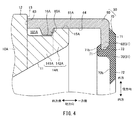
また、図4に変形例1として示すように、溝16の代わりに、外輪10Aの薄肉部14Aが第1薄肉部141A及び第2薄肉部142Aを含むことにより、薄肉部14Aに凹部が形成されていてもよい。
Further, as shown as
この場合、第1薄肉部141Aは、第2薄肉部142Aよりも径が小さく、第2薄肉部142Aの軸方向他方側に配置されている。そのため、薄肉部14Aの外周面15Aにおいて、第1薄肉部141Aの外周面が第2薄肉部142Aの外周面よりも凹んだ凹部16Aを構成する。潤滑油保持部材50のリング本体61Aに形成された凸部65は、凹部16Aの軸方向一方側において、凹部16Aに収容される。そのため、凸部65Aの軸方向他方側には、空間161Aが存在することとなる。
In this case, the first
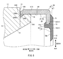
また、図5に変形例2として示すように、リング部材60のリング本体61の軸方向他方側の端部に凸部65Bが形成され、外輪10の薄肉部14Bのうち軸方向他方側の端部に凹部16Bが形成されていてもよい。こうすることにより、外輪10の薄肉部14Bの軸方向の大きさを小さくすることができ、外輪10の剛性を向上させることができる。
Further, as shown as
また、変形例2の円すいころ軸受によれば、凸部65Bの軸方向他方側の端部65Baとリング本体61Bの軸方向他方側の端面63Bとが同一である。また、外輪10の段差面13と凹部16の軸方向他方側の端部16Baとが同一である。そのため、外輪10をハウジングに取り付けるために潤滑油保持部材50に対して力を加えるとき、潤滑油保持部材50のリング本体61の凸部65の軸方向他方側の端部65Baが溝16Bの表面に接触するのと同時に、リング本体61Bの軸方向他方側の端面63Bが段差面13に接触する。したがって、外輪10の段差面13とリング本体61Bの軸方向他方側の端面63Bとの間に隙間が存在していても、潤滑油保持部材50に対して加えられた力を確実に外輪10に伝達することができる。
Further, according to the tapered roller bearing of the second modification, the end portion 65Ba on the other axial side of the
以上、上述した実施の形態は本発明を実施するための例示に過ぎない。よって、本発明は上述した実施の形態に限定されることなく、その趣旨を逸脱しない範囲内で上述した実施の形態を適宜変形して実施することが可能である。 As mentioned above, embodiment mentioned above is only the illustration for implementing this invention. Therefore, the present invention is not limited to the above-described embodiment, and can be implemented by appropriately modifying the above-described embodiment without departing from the spirit thereof.
1 円すいころ軸受
10 外輪
12 外輪の外周面
13 段差面
14 薄肉部
16 溝(凹部)
20 内輪
30 円すいころ
50 潤滑油保持部材
51 環状部
52 筒状部
65 凸部
DESCRIPTION OF
20
Claims (5)
外周面に第2の軌道面を有し、前記外輪と同軸上に配置された内輪と、
前記第1の軌道面及び前記第2の軌道面の間の空間に配置された複数の円すいころと、
前記外輪と一体に固定された潤滑油保持部材と、
を備えた円すいころ軸受であって、
前記外輪は、外周面に設けられた環状の段差面によって軸方向一方側の端部に環状の薄肉部が形成され、軸方向他方側の端部がハウジングに嵌め込まれ、
前記潤滑油保持部材は、
軸方向に延びる円筒状に形成され、軸方向他方側の端面が前記外輪の前記段差面に軸方向に対向し且つ前記薄肉部の外周面を覆うように配置された筒状部と、
径方向に延びる円環状に形成され、径方向外方における端部が前記筒状部の軸方向一方側の端部に接続された環状部と、
を含み、
前記筒状部は、内周面に、径方向内方に向かって突出して形成された凸部を有し、
前記薄肉部は、外周面に、前記凸部を収容可能で前記潤滑油保持部材の軸方向の移動を規制するように形成された凹部を有する、円すいころ軸受。 An outer ring having a first raceway surface on the inner peripheral surface;
An inner ring having a second raceway surface on the outer peripheral surface and disposed coaxially with the outer ring;
A plurality of tapered rollers disposed in a space between the first raceway surface and the second raceway surface;
A lubricant holding member fixed integrally with the outer ring;
A tapered roller bearing with
The outer ring is formed with an annular thin portion at one end in the axial direction by an annular step surface provided on the outer peripheral surface, and the other end in the axial direction is fitted into the housing,
The lubricating oil holding member is
A cylindrical portion that is formed in a cylindrical shape extending in the axial direction, and is disposed so that the end surface on the other side in the axial direction faces the step surface of the outer ring in the axial direction and covers the outer peripheral surface of the thin portion;
An annular portion formed in an annular shape extending in the radial direction, and an end portion on the radially outer side connected to an end portion on one axial side of the cylindrical portion;
Including
The cylindrical part has a convex part formed to project radially inward on the inner peripheral surface,
The thin-walled portion is a tapered roller bearing having, on an outer peripheral surface thereof, a concave portion that can accommodate the convex portion and is formed so as to restrict movement of the lubricating oil retaining member in the axial direction.
前記潤滑油保持部材における軸方向内方の端面から前記凸部の軸方向内方の端部までの距離は、前記外輪の前記段差面から前記凹部の軸方向内方の端部までの距離以上である、円すいころ軸受。 The tapered roller bearing according to claim 1,
The distance from the axially inner end surface of the lubricating oil holding member to the axially inner end portion of the convex portion is equal to or greater than the distance from the step surface of the outer ring to the axially inner end portion of the concave portion. It is a tapered roller bearing.
前記外輪の前記段差面は、軸方向に垂直な面を有し、
前記筒状部の前記軸方向内方の端面は、軸方向に垂直な面を有する、円すいころ軸受。 In the tapered roller bearing according to claim 1 or 2,
The step surface of the outer ring has a surface perpendicular to the axial direction,
A tapered roller bearing in which the axially inner end surface of the cylindrical portion has a surface perpendicular to the axial direction.
前記凹部は、前記薄肉部の外周面の全周に亘って溝状に形成されている、円すいころ軸受。 In the tapered roller bearing according to any one of claims 1 to 3,
The concave portion is a tapered roller bearing formed in a groove shape over the entire circumference of the outer peripheral surface of the thin portion.
前記凸部は、複数個形成されていると共に、前記筒状部の内周面に周方向に並び且つ等間隔で配置されている、円すいころ軸受。 In the tapered roller bearing according to any one of claims 1 to 4,
A tapered roller bearing in which a plurality of the convex portions are formed and arranged on the inner peripheral surface of the cylindrical portion in the circumferential direction at equal intervals.
Priority Applications (1)
| Application Number | Priority Date | Filing Date | Title |
|---|---|---|---|
| JP2016080001A JP6747026B2 (en) | 2016-04-13 | 2016-04-13 | Tapered roller bearing |
Applications Claiming Priority (1)
| Application Number | Priority Date | Filing Date | Title |
|---|---|---|---|
| JP2016080001A JP6747026B2 (en) | 2016-04-13 | 2016-04-13 | Tapered roller bearing |
Publications (2)
| Publication Number | Publication Date |
|---|---|
| JP2017190821A true JP2017190821A (en) | 2017-10-19 |
| JP6747026B2 JP6747026B2 (en) | 2020-08-26 |
Family
ID=60085829
Family Applications (1)
| Application Number | Title | Priority Date | Filing Date |
|---|---|---|---|
| JP2016080001A Expired - Fee Related JP6747026B2 (en) | 2016-04-13 | 2016-04-13 | Tapered roller bearing |
Country Status (1)
| Country | Link |
|---|---|
| JP (1) | JP6747026B2 (en) |
Cited By (1)
| Publication number | Priority date | Publication date | Assignee | Title |
|---|---|---|---|---|
| CN111434943A (en) * | 2019-01-11 | 2020-07-21 | 斯凯孚公司 | Rolling bearing unit and tapered roller bearing inner ring |
-
2016
- 2016-04-13 JP JP2016080001A patent/JP6747026B2/en not_active Expired - Fee Related
Cited By (2)
| Publication number | Priority date | Publication date | Assignee | Title |
|---|---|---|---|---|
| CN111434943A (en) * | 2019-01-11 | 2020-07-21 | 斯凯孚公司 | Rolling bearing unit and tapered roller bearing inner ring |
| CN111434943B (en) * | 2019-01-11 | 2023-09-19 | 斯凯孚公司 | Rolling bearing unit and tapered roller bearing inner race |
Also Published As
| Publication number | Publication date |
|---|---|
| JP6747026B2 (en) | 2020-08-26 |
Similar Documents
| Publication | Publication Date | Title |
|---|---|---|
| JP2010174979A (en) | Rolling bearing | |
| JP6717028B2 (en) | Ball bearing | |
| JP2016180417A (en) | Conical roller bearing | |
| CN112648285A (en) | Rolling bearing | |
| JP2015200393A (en) | Rolling bearing with seal ring | |
| JP6736875B2 (en) | Tapered roller bearing | |
| JP2017190821A (en) | Tapered roller bearing | |
| JP2008223995A (en) | Thrust roller bearing | |
| JP2012193858A (en) | Cage for thrust needle bearing and thrust needle bearing | |
| JP2007113628A (en) | Thrust roller bearing | |
| JP2017141876A (en) | Rolling bearing | |
| JP2015052349A (en) | Conical roller bearing | |
| JP2015121236A (en) | Self-aligning roller bearing | |
| JPH10318264A (en) | Synthetic resin cage for roller bearings | |
| JP2019086077A (en) | Deep groove ball bearings | |
| JP2018135957A (en) | Conical roller bearing | |
| JP2018062942A (en) | Rolling bearing | |
| JP2009030623A (en) | Tapered roller bearing | |
| JP2016200265A (en) | Thrust roller bearing | |
| US9670960B2 (en) | Radial rolling bearing assembly with connector sleeve | |
| WO2020162222A1 (en) | Solid-lubricant rolling bearing | |
| JP2013015201A (en) | Tapered roller bearing | |
| JP2020046061A (en) | Holder for conical roller bearing and conical roller bearing | |
| JP5321224B2 (en) | Rolling bearing | |
| JP6606903B2 (en) | Rolling bearing |
Legal Events
| Date | Code | Title | Description |
|---|---|---|---|
| A621 | Written request for application examination |
Free format text: JAPANESE INTERMEDIATE CODE: A621 Effective date: 20190318 |
|
| A977 | Report on retrieval |
Free format text: JAPANESE INTERMEDIATE CODE: A971007 Effective date: 20200116 |
|
| A131 | Notification of reasons for refusal |
Free format text: JAPANESE INTERMEDIATE CODE: A131 Effective date: 20200218 |
|
| A521 | Request for written amendment filed |
Free format text: JAPANESE INTERMEDIATE CODE: A523 Effective date: 20200326 |
|
| TRDD | Decision of grant or rejection written | ||
| A01 | Written decision to grant a patent or to grant a registration (utility model) |
Free format text: JAPANESE INTERMEDIATE CODE: A01 Effective date: 20200707 |
|
| A61 | First payment of annual fees (during grant procedure) |
Free format text: JAPANESE INTERMEDIATE CODE: A61 Effective date: 20200720 |
|
| R150 | Certificate of patent or registration of utility model |
Ref document number: 6747026 Country of ref document: JP Free format text: JAPANESE INTERMEDIATE CODE: R150 |
|
| LAPS | Cancellation because of no payment of annual fees |