JP2017190814A - Seat ring and butterfly valve - Google Patents
Seat ring and butterfly valve Download PDFInfo
- Publication number
- JP2017190814A JP2017190814A JP2016079681A JP2016079681A JP2017190814A JP 2017190814 A JP2017190814 A JP 2017190814A JP 2016079681 A JP2016079681 A JP 2016079681A JP 2016079681 A JP2016079681 A JP 2016079681A JP 2017190814 A JP2017190814 A JP 2017190814A
- Authority
- JP
- Japan
- Prior art keywords
- valve body
- seat ring
- valve
- ring
- component
- Prior art date
- Legal status (The legal status is an assumption and is not a legal conclusion. Google has not performed a legal analysis and makes no representation as to the accuracy of the status listed.)
- Pending
Links
- 239000012530 fluid Substances 0.000 claims description 33
- 238000007789 sealing Methods 0.000 claims description 11
- 238000011144 upstream manufacturing Methods 0.000 claims description 5
- 230000002093 peripheral effect Effects 0.000 description 11
- 238000004519 manufacturing process Methods 0.000 description 9
- 238000012856 packing Methods 0.000 description 9
- 238000003780 insertion Methods 0.000 description 6
- 230000037431 insertion Effects 0.000 description 6
- 229910001220 stainless steel Inorganic materials 0.000 description 6
- 239000010935 stainless steel Substances 0.000 description 6
- 230000000694 effects Effects 0.000 description 5
- 210000004907 gland Anatomy 0.000 description 5
- 229910001208 Crucible steel Inorganic materials 0.000 description 4
- 239000000463 material Substances 0.000 description 3
- 239000002184 metal Substances 0.000 description 3
- 238000000034 method Methods 0.000 description 3
- 238000012545 processing Methods 0.000 description 3
- 238000004458 analytical method Methods 0.000 description 2
- 238000004364 calculation method Methods 0.000 description 2
- 239000000470 constituent Substances 0.000 description 2
- 230000007423 decrease Effects 0.000 description 2
- 238000003825 pressing Methods 0.000 description 2
- 125000006850 spacer group Chemical group 0.000 description 2
- OKTJSMMVPCPJKN-UHFFFAOYSA-N Carbon Chemical compound [C] OKTJSMMVPCPJKN-UHFFFAOYSA-N 0.000 description 1
- 239000012141 concentrate Substances 0.000 description 1
- -1 for example Substances 0.000 description 1
- 229910002804 graphite Inorganic materials 0.000 description 1
- 239000010439 graphite Substances 0.000 description 1
- 230000001771 impaired effect Effects 0.000 description 1
- 239000007769 metal material Substances 0.000 description 1
- 230000000149 penetrating effect Effects 0.000 description 1
- 239000011347 resin Substances 0.000 description 1
- 229920005989 resin Polymers 0.000 description 1
- 238000012360 testing method Methods 0.000 description 1
Images


Landscapes
- Lift Valve (AREA)
Abstract
Description
本発明は、バタフライバルブを構成するシートリング、及び、そのシートリングを有するバタフライバルブに関する。 The present invention relates to a seat ring constituting a butterfly valve, and a butterfly valve having the seat ring.
バタフライバルブは、一般的に、管状の流路を有する弁本体の内周に弁座となるシートリングが設けられており、流体は、シートリングを含む仮想平面と直交する方向に流れる。 A butterfly valve is generally provided with a seat ring serving as a valve seat on the inner periphery of a valve body having a tubular flow path, and the fluid flows in a direction perpendicular to a virtual plane including the seat ring.
弁本体の内側には、シートリングの内周面に当接する外周面を有する弁体が設けられている。弁体には、流路と直交する方向に軸孔が開設されており、軸孔には、中空部(流路)を貫通するように弁本体に設けられた弁軸が挿入されている。弁体は弁軸に固定されており、弁軸がその軸心を中心として回動されることにより弁体が回動されて流路の開閉がなされる。 A valve body having an outer peripheral surface that comes into contact with the inner peripheral surface of the seat ring is provided inside the valve main body. A shaft hole is formed in the valve body in a direction perpendicular to the flow path, and a valve shaft provided in the valve main body is inserted into the shaft hole so as to penetrate the hollow portion (flow path). The valve body is fixed to the valve shaft, and the valve body is rotated by rotating the valve shaft about its axis to open and close the flow path.
ここで、シートリングにおける弁体との接触面となる外周面を「固定シール面」と称し、弁体におけるシートリングの外周面との接触面を「可動シール面」と称することとする。 Here, an outer peripheral surface that is a contact surface with the valve body in the seat ring is referred to as a “fixed seal surface”, and a contact surface with the outer peripheral surface of the seat ring in the valve body is referred to as a “movable seal surface”.
高温(約250℃〜約820℃)の流体用のバタフライ弁の場合、高温の流体が直接接触する弁体の温度が高温となる。このため、弁体及びシートリングが膨張変形し、固定シール面と可動シール面とのシール性が損なわれることがあった。一方で、シール性を向上させるために、固定シール面と可動シール面との接触圧力を高めると、弁体を閉めるトルクが高くなり、弁体を回動させる動力ユニットの負荷が大きくなる。また、シートリングをNC旋盤等のNC工作機によって加工するためには、コンピューターによる補間計算を行ってNCデータを作成する必要があり、加工コストが嵩んだ。このため、シートリングの製造コストの低減が求められている。 In the case of a butterfly valve for a fluid having a high temperature (about 250 ° C. to about 820 ° C.), the temperature of the valve body in direct contact with the high temperature fluid is high. For this reason, the valve body and the seat ring may expand and deform, and the sealing performance between the fixed seal surface and the movable seal surface may be impaired. On the other hand, when the contact pressure between the fixed seal surface and the movable seal surface is increased in order to improve the sealing performance, the torque for closing the valve body increases, and the load on the power unit that rotates the valve body increases. Further, in order to process the seat ring with an NC machine tool such as an NC lathe, it is necessary to create NC data by performing interpolation calculation with a computer, which increases the processing cost. For this reason, reduction of the manufacturing cost of a seat ring is calculated | required.
なお、高温用のバタフライバルブを構成するシートリング、及び、そのシートリングを有するバタフライバルブに関する特許文献としては、弁体の可動シール面とシートリングの固定シール面とのシール性の向上に関する文献が存在する(特許文献1参照。)。しかし、本願発明に関連するものはない。 In addition, as a patent document relating to a seat ring constituting a high temperature butterfly valve and a butterfly valve having the seat ring, there is a document relating to an improvement in sealing performance between a movable seal surface of a valve body and a fixed seal surface of a seat ring. Exists (see Patent Document 1). However, there is nothing related to the present invention.
本発明は、可動シール面と固定シール面とのシール性を確保しながらも、弁体を閉じるためのトルクを最小にでき、しかも製造コストを低減できるシートリング及びバタフライバルブを提供することを目的とする。 An object of the present invention is to provide a seat ring and a butterfly valve capable of minimizing torque for closing a valve body and reducing manufacturing cost while ensuring sealing performance between a movable seal surface and a fixed seal surface. And
本発明のシートリングは、バタフライバルブに備えられ、
流体が流れる管状の流路を有する弁本体と、前記流路内に設けられ、該流体の流れ方向に対して垂直な弁棒を回動中心軸として該流路内で回動される弁体と、の間に設けられるリング形状のシートリングであって、
前記流路の断面の外周円に沿って前記弁本体に固定される固定部と、前記固定部と一体的に形成され、前記弁体に接触する接触部と、前記固定部及び前記接触部の中間に、該固定部及び該接触部と一体的に形成された中間部と、を備え、
前記接触部は、
前記中間部に隣接し、円錐高さ線が前記流体の流れ方向と平行であり、円錐の頂点が前記弁体よりも前記流体の流れ方向下流側に位置する円錐台筒状の第一構成部と、
前記第一構成部に隣接し、前記リング形状の円周方向に対する垂直断面において、前記弁体へ向かって突出する円弧状であり、該弁体に接触する第二構成部と、
前記第二構成部に隣接し、円錐高さ線が前記流体の流れ方向と平行であり、円錐の頂点が前記弁体よりも前記流体の流れ方向上流側に位置する円錐台筒状の第三構成部と、から構成されたことを特徴とする。
本願明細書及び特許請求の範囲において、円錐高さ線とは、円錐形状の底面の中心から円錐の頂点に至る線である。円錐台筒状とは、筒状であって、円錐高さ線を含む断面において円錐台である形状である。円弧とは円の一部である。
本発明のシートリングは、前記シートリングにおいて、シートリングの前記リング形状の円周方向に対する垂直断面において、外輪郭線が、直線及び円弧線のみから構成されることを特徴とする。
本発明のシートリングは、前記シートリングにおいて、前記リング形状の円周方向に対する垂直断面における第一構成部の長さを。該リング形状の円周方向に対する垂直断面における第三構成部の長さで除した値が、2.7以上、4.3以下であることを特徴とする。
本発明のバタフライバルブは、管状の流路を有する弁本体と、前記弁本体に回動自在に設けられた弁棒と、前記弁棒により回動され、前記流路を開閉する弁体と、前記シートリングと、を備えたことを特徴とする。
本発明のバタフライバルブは、前記バタフライバルブにおいて、前記弁体の外周のシール面が、前記シートリングのリング形状の円周方向に対する垂直断面において、該リング形状の外側へ突出する円弧状であることを特徴とする。
The seat ring of the present invention is provided in a butterfly valve,
A valve body having a tubular flow path through which a fluid flows, and a valve body provided in the flow path and rotated in the flow path with a valve rod perpendicular to the flow direction of the fluid as a rotation center axis A ring-shaped seat ring provided between and
A fixed portion fixed to the valve main body along an outer peripheral circle of a cross section of the flow path, a contact portion formed integrally with the fixed portion and in contact with the valve body, and the fixed portion and the contact portion. An intermediate portion formed integrally with the fixed portion and the contact portion;
The contact portion is
A first truncated cone-shaped first component that is adjacent to the intermediate portion, has a conical height line parallel to the fluid flow direction, and a vertex of the cone is located downstream of the valve body in the fluid flow direction. When,
A second component that is adjacent to the first component and has a circular arc shape projecting toward the valve body in a vertical cross section with respect to the circumferential direction of the ring shape, and is in contact with the valve body;
A truncated cone-shaped third cylinder adjacent to the second component, having a cone height line parallel to the fluid flow direction, and a vertex of the cone positioned upstream of the valve body in the fluid flow direction. And a constituent part.
In the present specification and claims, the cone height line is a line from the center of the bottom surface of the cone shape to the apex of the cone. A truncated cone shape is a shape that is a truncated cone in a cross section including a cone height line. An arc is a part of a circle.
The seat ring of the present invention is characterized in that, in the seat ring, an outer contour line is composed of only a straight line and an arc line in a vertical cross section of the seat ring with respect to the circumferential direction of the ring shape.
In the seat ring according to the present invention, the length of the first component portion in the cross section perpendicular to the circumferential direction of the ring shape in the seat ring. A value obtained by dividing the ring shape by the length of the third component in the vertical cross section with respect to the circumferential direction is 2.7 or more and 4.3 or less.
The butterfly valve of the present invention includes a valve body having a tubular flow path, a valve rod rotatably provided on the valve body, a valve body that is rotated by the valve rod and opens and closes the flow path, The seat ring is provided.
In the butterfly valve according to the present invention, in the butterfly valve, the sealing surface on the outer periphery of the valve body has an arc shape that protrudes outside the ring shape in a cross section perpendicular to the circumferential direction of the ring shape of the seat ring. It is characterized by.
本発明のシートリング及びバタフライバルブによれば、弁体に向かって突出する円弧状の第二構成部が弁体に接触する。すなわち、円弧状の第二構成部の稜線が弁体に接触し、シートリングのリング形状の円周方向に対する垂直断面において、接触部と弁体とは略点接触し、しかも弁体が熱によって膨張しても接触部と弁体とは略点接触する。このため、接触部と弁体との間の単位面積当たりの抗力(押圧力)を高めて、接触部と弁体との間のシール性を確保できる。また、シートリングのリング形状の円周方向に対する垂直断面において、接触部と弁体とは略点接触するため、接触部と弁体との摩擦力を最小に抑え、弁体を開閉する時の弁体を回動するためのトルクを最小に抑えることができる。 According to the seat ring and the butterfly valve of the present invention, the arc-shaped second component projecting toward the valve body comes into contact with the valve body. That is, the ridge line of the arc-shaped second component part contacts the valve body, and the contact part and the valve body are substantially point-contacted in the vertical cross section of the ring shape of the seat ring with respect to the circumferential direction. The contact portion and the valve body are substantially in point contact even when expanded. For this reason, the drag per unit area (pressing force) between a contact part and a valve body can be raised, and the sealing performance between a contact part and a valve body can be ensured. In addition, in the vertical cross section of the seat ring ring shape in the circumferential direction, the contact portion and the valve body are in substantially point contact, so the frictional force between the contact portion and the valve body is minimized, and the valve body is opened and closed. Torque for rotating the valve body can be minimized.
ここで、本発明のシートリング及びバタフライバルブによれば、円弧状の第二構成部が弁体に接触し、シートリングの角部が弁体に接触する構成ではない。このため、弁体を開閉する時に、シートリングが弁体を損傷することはない。すなわち、本発明のシートリング及びバタフライバルブによれば、シートリングと弁体とは略点接触しながらも、弁体を開閉する時に、シートリングが弁体を損傷することはない。 Here, according to the seat ring and the butterfly valve of the present invention, the arc-shaped second constituent portion is not in contact with the valve body, and the corner portion of the seat ring is not in contact with the valve body. For this reason, when opening and closing a valve body, a seat ring does not damage a valve body. That is, according to the seat ring and the butterfly valve of the present invention, the seat ring does not damage the valve body when the valve body is opened and closed, while the seat ring and the valve body are in substantially point contact.
また、本発明のシートリング及びバタフライバルブによれば、接触部は、円錐台筒状の第一構成部と、シートリングのリング形状の円周方向に対する垂直断面において円弧状である第二構成部と、円錐台筒状の第三構成部と、から構成される。すなわち、シートリングのリング形状の円周方向に対する垂直断面において、第一構成部の外輪郭線が直線から構成され、第二構成部の外輪郭線が円弧線から構成され、第三構成部の外輪郭線が直線から構成され、接触部の外輪郭線が、直線及び円弧線のみから構成される。このため、最も精度良く加工することが必要な接触部を加工するためのNCデータの作成が容易となる。これにより、NC旋盤等のNC工作機によって接触部を容易且つ迅速に加工でき、シートリング及びバタフライバルブの製造コストを低減できる。 Further, according to the seat ring and the butterfly valve of the present invention, the contact portion includes the first component portion having a truncated cone shape and the second component portion having an arc shape in a vertical cross section with respect to the circumferential direction of the ring shape of the seat ring. And a third component having a truncated cone shape. That is, in the vertical cross section of the ring shape of the seat ring with respect to the circumferential direction, the outer contour line of the first component portion is configured from a straight line, the outer contour line of the second component portion is configured from an arc line, The outer contour line is composed of a straight line, and the outer contour line of the contact portion is composed of only a straight line and an arc line. For this reason, it becomes easy to create NC data for processing a contact portion that needs to be processed with the highest accuracy. Accordingly, the contact portion can be processed easily and quickly by an NC machine tool such as an NC lathe, and the manufacturing cost of the seat ring and the butterfly valve can be reduced.
また、シートリングのリング形状の円周方向に対する垂直断面において、全ての外輪郭線が、直線及び円弧線のみから構成される本発明のシートリング及びバタフライバルブによれば、シートリング全体をNC旋盤等のNC工作機によって容易且つ迅速に加工でき、シートリング及びバタフライバルブの製造コストを更に低減できる。 In addition, according to the seat ring and the butterfly valve of the present invention in which all the outer contour lines are composed of only a straight line and an arc line in the cross section perpendicular to the circumferential direction of the ring shape of the seat ring, the entire seat ring is an NC lathe. It can be processed easily and quickly by an NC machine tool such as the above, and the manufacturing cost of the seat ring and the butterfly valve can be further reduced.
以下、本発明のシートリング、そのシートリングを備えた本発明のバタフライバルブについて、図面を参照しながら説明する。図1〜図8において符号10は本発明のバタフライバルブを示し、符号18は本発明のシートリングを示す。なお、図1及び図2は、シートリング18と弁体20との現実の接触状態を示し、図3及び図4は、シートリング18の締め代dの寸法等を説明するために、2点鎖線で示す弁体20にシートリング18が入り込んだ仮想状態を示す。また、図1〜図8において、流体の流れる方向F(図1及び図2に示す。)と平行な方向をX軸とし、弁体20の回動中心軸C(図1に示す。)の方向をZ軸とし、X軸及びZ軸に垂直な方向をY軸としている。なお、流体は方向Fと逆方向に流れることも可能である。
Hereinafter, a seat ring of the present invention and a butterfly valve of the present invention including the seat ring will be described with reference to the drawings. 1 to 8,
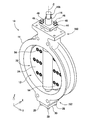
図1に示すように、バタフライバルブ10は、管状の流路12を有する弁本体14と、弁本体14に回動自在に設けられた弁棒16と、弁本体14の内周に設けられた弁座であるシートリング18と、弁棒16で回動自在に軸支されて弁本体14内側に収納された弁体20とを有する。
As shown in FIG. 1, the
(弁本体)
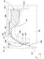
弁本体14は、例えば、温度変化による強度変化の少ないステンレス鋳鋼で形成されている。ステンレス鋳鋼としては、例えば、SCS13が選択される。弁本体14は、略リング形状(環状)をなし、内径部の一端側には、円形状の流路12が形成され、他端側には、略円形状のシートリング18の取付部が形成されている。弁本体14の外径部には、弁本体14が変形しないように、フランジが複数条形成されている。弁本体14の底部には、図5及び図6に示すように、4本のボルト28(図5で、2本のみが表れ、図6で、1本のみが表れている)によって、底カバー30が取り付けられている。底カバー30と弁本体14との間には、リング形状をしたガスケット31が挟み込まれており、これによって、流体が弁本体14の外部へ漏出するのが防止されている。
(Valve body)
The valve
弁本体14の上部には、2本の植込みボルト46(図5)の一端側が螺入されている。植込みボルト46は、グランドフランジ44の対角近傍に開設された貫通孔(不図示)に挿入されており、グランドフランジ44から上方に突出した他端側には、ナット48(図5)が螺合されている。そして、ナット48を締め付けることにより、グランドフランジ44が、パッキン押さえ42を下向きに押圧することとなる。図5〜図8に示すように、弁本体14には、その上部と底部を貫く弁棒16を軸支する上部軸支部150と底部軸支部152とが形成されている。上部軸支部150には、軸ブッシュ38がグランドパッキン40を介して固定され、底部軸支部152には、軸ブッシュ27は底カバー30により固定されている。軸ブッシュ27及び38により、弁棒16が円滑に回動できる。
One end side of two stud bolts 46 (FIG. 5) is screwed into the upper part of the
(弁棒)
弁棒16は、例えば、温度変化による強度変化の少ないステンレス鋼で形成されている。ステンレス鋼としては、例えば、SUS304、SUS630等が選択される。図1に示すように、弁棒16は、第2弁体部24に開設された軸孔26に挿入されていて、弁棒16は、第2弁体部24において弁体20全体を軸支している。なお、第2弁体部24の軸孔26と弁棒16には、対応するキー溝(いずれも、不図示)が形成されており、両キー溝には、不図示のキーが嵌入されている。これにより、弁棒16のトルクが弁体20(第2弁体部24)に伝達されて、弁棒16により弁体20が回動されることとなる。
(Valve stem)
The valve stem 16 is formed of, for example, stainless steel that hardly changes in strength due to a temperature change. As the stainless steel, for example, SUS304, SUS630, or the like is selected. As shown in FIG. 1, the
弁棒16は、図5及び図6に示すように、流路12を貫通し、その上部と下部とがそれぞれ軸ブッシュ38,27を介して弁本体14に支持されている。軸ブッシュ27は、メタル、グラファイト等で形成され円筒状をしており、弁棒16の下部に外挿されている。
As shown in FIGS. 5 and 6, the
図5及び図6に示すように、底カバー30と弁棒16の下端との間には、円板部材32とリング部材34が設けられている。円板部材32は、フッ素樹脂や砲金等で形成されており、ボルト36で弁棒16の下端面に取り付けられている。リング部材34は、金属材料(例えば、ステンレス鋼)で形成されている。円板部材32とリング部材34とで、弁棒16に掛かるスラスト荷重を受けている。
As shown in FIGS. 5 and 6, a
一方、弁棒16の上部には、図5及び図6に示すように、下から順に、軸ブッシュ38、グランドパッキン40、パッキン押さえ42が外挿されている。パッキン押さえ42は、方形板状をしたグランドフランジ44によって、弁棒16の軸心方向で下向きに押圧されており、グランドパッキン40は、パッキン押さえ42によって締め付けられている。これにより、グランドパッキン40に弁棒16表面を押付ける力が発生し、グランドパッキン40が弁棒16に密着することにより、弁棒16伝いに弁本体14外部へ流体が漏出するのが防止されている。
On the other hand, as shown in FIGS. 5 and 6, a
(弁体)
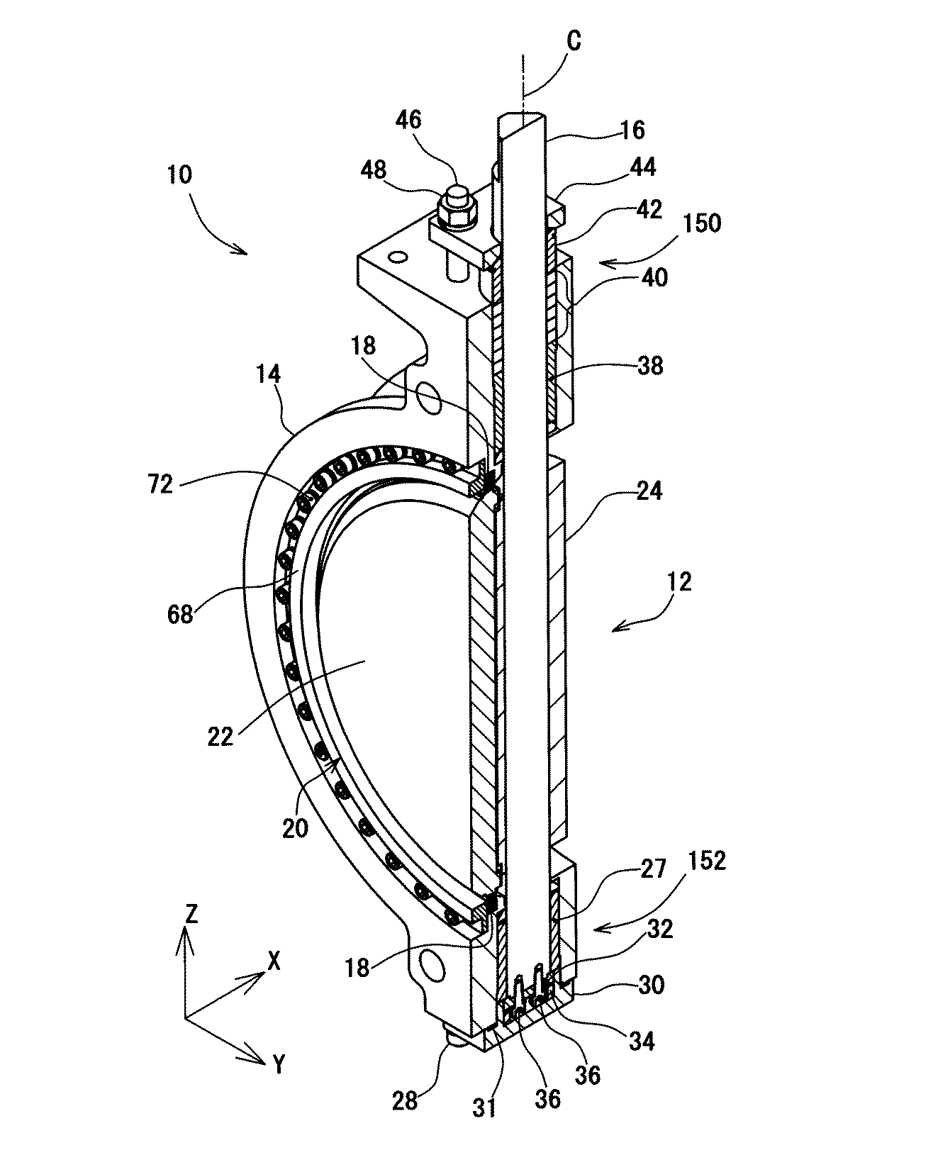
弁体20は、図1に示すように、弁棒16に固定された第2弁体部24と、その第2弁体部24に重ね合わされるように固定された円盤状をした第1弁体部22とを含む。第1弁体部22と第2弁体部24は、同種の材料、例えば、温度変化による強度変化の少ないステンレス鋳鋼で形成されている。ステンレス鋳鋼としては、例えば、SCS13が選択される。弁体20の外周の可動シール面22Aは、図2に示すように、シートリング18のリング形状の円周方向に対する垂直断面(以下、「リング断面」と言う。)において、リング形状の外側へ突出する円弧状である。また、可動シール面22Aの円弧の半径は、弁体20が回動する時の可動シール面22Aの円弧の頂上の軌跡318の半径よりも小さく構成されている。
(Valve)
As shown in FIG. 1, the
図1に示すように、第1弁体部22と第2弁体部24とは、締結部材である複数本の六角穴付きボルト54(以下、単に「ボルト54」と言う。)によって、それらの厚み方向に締結される。また、図1及び図7に示すように、第1弁体部22と第2弁体部24との間には、スペーサ部材56が差し挟まれて配されている。スペーサ部材56は、第1シム58と第2シム60とを含む。第1シム58は、円板状をしており第1弁体部22の中心領域に配されている。第2シム60は、環状をしていて、第1シム58を取り囲むように配されている。第1シム58と第2シム60とは、ゴム、樹脂、ガスケット等から構成されている。
As shown in FIG. 1, the first
図7に示すように、第1シム58および第2シム60を間に挟んで、第1弁体部22と第2弁体部24を複数のボルト54で締結することにより、弁体20が組み立てられる。弁体20において、第1弁体部22の最外周面は、円弧面を成し、最外周面がバタフライバルブ10の全閉時において、図2に示すように、シートリング18の内周面18Aと接触する接触面となる。以下、シートリング18の内周面と接触する第1弁体部22の外周面を「可動シール面22A」と称することとする。また、可動シール面22Aと同様に円錐面の一部を成し、可動シール面22Aと接触するシートリング18の内周面を「固定シール面18A」と称することとする。
As shown in FIG. 7, the
図7に示すように、第2弁体部24には、所定の複数位置に、ザグリ加工の施されたボルト挿通孔50(以下、単に「挿通孔50」と言う。)が厚み方向に開設されている。一方、第1弁体部22には、第2弁体部24に重ねられた状態において、各挿通孔50に対応する位置にねじ穴52が形成されている。ねじ穴52の各々は、全て、第1弁体部22の厚み方向に貫通していない有底のねじ穴である。
As shown in FIG. 7, bolt insertion holes 50 (hereinafter simply referred to as “insertion holes 50”) that are subjected to counterboring are formed in the second
(シートリング)
シートリング18は、図1に示すように、弁本体14に回動自在に設けられた弁棒16により回動される弁体20と協働して流路12を開閉するように構成されている。シートリング18は、金属から構成され、例えばステンレス鋼から構成される。ステンレス鋼としては、例えば、SUS316、又はSUS304等が選択される。ステンレス鋼の表面にメッキを施してもよい。
(Seat ring)
As shown in FIG. 1, the
シートリング18は、図2及び図3に示すように、弁本体14に固定される固定部300と、弁体20に接触するリング形状の接触部304と、固定部300及び接触部304の中間に、固定部300及び接触部304と一体的に形成された中間部302と、を備えている。シートリング18全体は、リング断面において、輪郭線が、直線及び円弧線のみから構成されている。シートリング18全体は、NC旋盤等のNC工作機によって加工し製造する。
As shown in FIGS. 2 and 3, the
次に、シートリング18の弁本体14への取付構造について説明する。図7に示すように、弁本体14に対し、環状をしたシートガスケット66−1、シートリング18、シートガスケット66−2、およびセットリング68がこの順で取り付けられる。セットリング68には、その周方向に複数のボルト挿通孔70(図7)が開設されており、弁本体14には、ボルト挿通孔70の各々に対応させてねじ穴14Bが形成されている。そして、ボルト挿通孔70に挿入した六角穴付きボルト72を弁本体14のねじ穴14Bに螺合することにより、セットリング68ひいてはシートガスケット66−1、シートリング18、及びシートガスケット66−2が、弁本体14に固定される。
Next, a structure for attaching the
シートガスケット66−1は、図1に示すように、弁本体14とシートリング18とで挟持されており、シートガスケット66−2は、セットリング68とシートリング18とで挟持されており、挟持部分において、全閉時に流体が上流側から下流側、並びに下流側から上流側へ漏れるのが防止されている。
As shown in FIG. 1, the seat gasket 66-1 is sandwiched between the
(固定部)
固定部300は、図2及び図3に示すように、シートリング18を弁本体14に固定するために、シートガスケット66−1又はシートガスケット66−2を介して、弁本体14及びセットリング68によって挟持される部分である。固定部300は、流路12の断面の外周円に沿って弁本体14に固定される
(Fixed part)
As shown in FIGS. 2 and 3, the fixing
(接触部)
接触部304は、図2に示すように、固定部300及び後述の中間部302と一体的に形成され、弁体20に接触する。接触部304は、図3に示すように、中間部302に連続する円錐台筒状(筒状であって、後述の円錐高さ線を含む断面において円錐台である形状)の第一構成部306と、第一構成部306に連続する第二構成部308と、第二構成部308に連続する円錐台筒状の第三構成部310と、から構成されている。
(Contact part)
As shown in FIG. 2, the
第一構成部306は、円錐高さ線(円錐形状の底面の中心から円錐の頂点に至る線)が流体の流れ方向F(図1及び図2に示す。)と平行であり、円錐の頂点が弁体よりも流体の流れ方向Fの下流側に位置する。第二構成部308は、第一構成部306に隣接し、リング断面において、弁体20に向かって突出する円弧状となっている。円弧状の第二構成部308の稜線が弁体20に接触する。弁体20の外周の可動シール面22Aは、図2に示すように、リング断面において、シートリング18のリング形状の外側へ突出する円弧状であるため、第二構成部308と弁体20とは、リング断面において、略点接触する。しかも、可動シール面22Aの円弧の半径は、弁体20が回動する時の可動シール面22Aの円弧の頂上の軌跡318の半径よりも小さく、第二構成部308と弁体20との接触面積は最小限に抑えられている。第三構成部310は、第二構成部308に隣接し、円錐高さ線が流体の流れ方向Fと平行であり、円錐の頂点が弁体20よりも流体の流れ方向Fの上流側に位置する
The
(中間部)
中間部302は、弁本体14に固定される固定部300と、弁体20に接触する接触部304との中間に、固定部300及び接触部304と一体的に形成されることにより、接触部304が弁体20に接触した状態を維持する部分である。固定部300から中間部302に連続する部分には、図2及び図3に示すように、リング断面において円弧形状の凹部320が設けられている。有限要素法により解析したところ、固定部300から中間部302に連続する部分に応力が集中することが判明した。このため、固定部300から中間部302に連続する部分において、固定部300から中間部302へいくに従って、厚みが急激に薄くなることなく、徐々に薄くなるように構成した。
(Middle part)
The
第一構成部306と中間部302とは、リング断面において円弧状である円弧部312を介して連続している。中間部302と円弧部312との接続部314は、リング断面において、円弧形状の凹部316が形成されている。有限要素法により解析したところ、中間部302と接触部304との接続部付近に応力が集中していることが判明した。このため、中間部302と接触部304との接続部である円弧部312及び接続部314において、中間部302から接触部304へいくに従って、厚みが急激に薄くなることなく、徐々に薄くなるように構成し、応力集中が生じないようにした。
The
(バタフライバルブの作動)
上述のような構成のバタフライバルブ10は、シートリング18の第二構成部308が弁体20と接触することにより、弁体20とシートリング18とのシール性が確保される。バタフライバルブ10は、全閉時において、第1弁体部22の可動シール面22Aとシートリング18の固定シール面18Aとが略線接触(リング断面において点接触)することにより流体の流路が遮断される。バタフライバルブ10は、図1、図6、及び図8に示す全閉状態から弁棒16を、図1に示す矢印Bの向きに90度回動させることによって、図5に示す全開状態となる。また、全開状態から、矢印Bとは反対向きに弁棒16を90度回動させることによって、全閉状態となる。弁棒16は、弁本体14の上端に取り付けられる不図示の動力ユニットによって、弁棒16の上端部分に形成された四角部16Aにトルクが加えられて回動される。この動力ユニットは、レバー式、ギヤー式、シリンダ式、電動式などの公知のものが用いられる。
(Butterfly valve operation)
In the
(本発明の効果)
本発明のシートリング18及びバタフライバルブ10によれば、高温流体によって弁体が膨張しても、接触部304が有する円弧状の第二構成部308の稜線が弁体20に接触する。すなわち、リング断面おいて、接触部304と弁体20とは略点接触する。このため、接触部304と弁体20との間の単位面積当たりの抗力(押圧力)を高めて、接触部304と弁体20との間のシール性を確保できる。また、リング断面において、接触部304と弁体20とは略点接触するため、接触部304と弁体20との摩擦力を最小に抑え、弁体20を開閉する時の弁体20を回動するためのトルクを最小に抑えることができる。
(Effect of the present invention)
According to the
ここで、本発明のシートリング18及びバタフライバルブ10によれば、円弧状の第二構成部308が外側へ突出する円弧状である弁体20に接触し、シートリングの角部が弁体20に接触する構成ではない。このため、弁体20を開閉する時に、シートリングが弁体20を損傷することはない。すなわち、本発明のシートリング18及びバタフライバルブ10によれば、シートリング18と弁体20とは略点接触しながらも、弁体20を開閉する時に、シートリング18が弁体を損傷するのを防止できる。
Here, according to the
また、本発明のシートリング18及びバタフライバルブ10によれば、リング断面において、全ての外輪郭線が、直線及び円弧線のみから構成される。このため、シートリング18全体を加工するためのNCデータを作成するためには、直線補間及び円弧補間の計算のみをコンピューターが行えばよく、NCデータの作成が容易となる。これにより、NC旋盤等のNC工作機によってシートリング18全体を容易且つ迅速に加工でき、シートリング18及びバタフライバルブ10の製造コストを低減できる。
Further, according to the
次に、本発明のシートリング18及びバタフライバルブ10について、高温(約300℃)の流体について、流体圧力2.0MPaで試験した結果、流体漏れがなくシール性が良好であった場合のシートリング18及び弁体20の各部の寸法を以下の表1に示す。試験において、弁体20の材質はSCS13で、シートリング18の材質はSUS316である。なお、高温時又は低温時の熱変形に対応した最適寸法で製造することも可能である。
Next, the
表1において、kは呼び径であり、呼び径とは、JIS B2001に基づく配管の呼び径(A呼称)の値である。表1及び図4において、R0は、弁体20の円弧状の可動シール面22Aの半径であり、単位はmmである。L1は、第三構成部310の長さであり、L2は、第一構成部306の長さであり、単位はmmである。R1は、円弧状の固定シール面18Aの半径であり、R2は、円弧状の円弧部312の半径であり、R3は、円弧状の中間部302の半径であり、単位はmmである。
In Table 1, k is a nominal diameter, and the nominal diameter is a value of a nominal diameter (A designation) of piping based on JIS B2001. In Table 1 and FIG. 4, R0 is the radius of the arc-shaped
表1及び図4において、dは、可動シール面22Aと固定シール面18Aとが接触して、可動シール面22Aと固定シール面18Aとの接触点における固定シール面18Aの接線に対する垂直方向に、固定シール面18Aが移動する距離である締め代であり、単位はmmである。なお、可動シール面22Aと固定シール面18Aとの接触点における固定シール面18Aの接線に対する垂直方向の線Lの上に、弁体20の回動中心軸C(図1に示す。)が位置する。S1は、第三構成部310の先端とセットリング68との、流体の流れ方向の隙間幅であり、S2は、第三構成部310の先端とセットリング68との、流体の流れ方向に対する垂直方向の隙間幅であり、単位はmmである。
In Table 1 and FIG. 4, d is a direction perpendicular to the tangent of the fixed
表1及び図4において、θ1は、第一構成部306と第三構成部310との角度であり、θ2は、第一構成部306の流体の流れ方向に対する垂直方向に対する角度であり、単位は度(°)である。θ3は、線Lの流体の流れ方向に対する垂直方向に対する角度であり、θ4は、第三構成部310と線Lとの角度であり、θ5は、第一構成部306と線Lとの角度であり、単位は度(°)である。
In Table 1 and FIG. 4, θ1 is the angle between the
シートリング18及び弁体20の各部の寸法が上記表1の場合にシール性が良好であったことから、以下のような数値条件の場合に、シール性が良好であり、シートリング18及び弁体20として好ましいと言える。
Since the sealing performance was good when the dimensions of each part of the
R0は、12mm以上、42mm以下であることが好ましい。tは、0.2mm以上、0.8mm以下が好ましい。k/R0は、3.5以上、19.0以下であることが好ましい。k/tは、150以上、930以下であることが好ましい。 R0 is preferably 12 mm or more and 42 mm or less. t is preferably 0.2 mm or more and 0.8 mm or less. k / R0 is preferably 3.5 or more and 19.0 or less. k / t is preferably 150 or more and 930 or less.
L1は、0.75mm以上、2.6mm以下であることが好ましい。L2は、3.35mm以上、8.20以下であることが好ましい。L2/L1は、2.7以上、4.3以下であることが好ましい。R1は、1.2mm以上、2.9mm以下であることが好ましい。R2は、1.2mm以上、2.9mm以下であることが好ましい。R3は、1.4以上、4.1以下であることが好ましい。 L1 is preferably 0.75 mm or more and 2.6 mm or less. L2 is preferably 3.35 mm or more and 8.20 or less. L2 / L1 is preferably 2.7 or more and 4.3 or less. R1 is preferably 1.2 mm or more and 2.9 mm or less. R2 is preferably 1.2 mm or more and 2.9 mm or less. R3 is preferably 1.4 or more and 4.1 or less.
dは、0.08mm以上、0.50mm以下であることが好ましい。k/dは、240以上、1800以下であることが好ましい。 d is preferably 0.08 mm or more and 0.50 mm or less. k / d is preferably 240 or more and 1800 or less.
S1は、0.4mm以上、0.8mm以下であることが好ましい。S2は、1.10mm以上、2.60mm以下であることが好ましい。 S1 is preferably 0.4 mm or more and 0.8 mm or less. S2 is preferably 1.10 mm or more and 2.60 mm or less.
θ1は、115度以上、140度以下であることが好ましい。θ2は、40度以上、65度以下であることが好ましい。θ3は、11.00度以上、27.00度以下であることが好ましい。θ4は、115.00度以上、140.00度以下であることが好ましい。θ5は、97.0度以上、110.00度以下であることが好ましい。 θ1 is preferably 115 degrees or more and 140 degrees or less. θ2 is preferably 40 degrees or more and 65 degrees or less. θ3 is preferably 11.00 degrees or more and 27.00 degrees or less. θ4 is preferably 115.00 degrees or more and 140.00 degrees or less. θ5 is preferably 97.0 degrees or more and 110.00 degrees or less.
以上、本発明の一実施形態について図面に基づいて説明したが、本発明は、上述の実施形態に限定されない。例えば、図9に示すシートリング18であってもよい。図9に示すシートリング18は、図3に示す凹部320を設けないで、リング断面において直線状の斜面321を設けている。図9に示すシートリング18は、図3に示す凹部320を設けないこと以外は、図3に示すシートリング18と同じ構成である。図9に示すシートリング18によっても、図3に示すシートリング18の上述の効果が生じる。さらに、リング断面における外輪郭線の円弧形状を減らして、NC旋盤等のNC工作機によるシートリング18の製造コストを、より低減できる。
As mentioned above, although one Embodiment of this invention was described based on drawing, this invention is not limited to the above-mentioned embodiment. For example, the
また、図10に示すシートリング18であってもよい。図10に示すシートリング18は、図3に示す凹部320及び円弧部312を設けないで、リング断面において直線状の斜面321を設け、円錐台形状のテーパ部313を設けている。図10に示すシートリング18は、図3に示す凹部320及び円弧部312を設けないこと以外は、図3に示すシートリング18と同じ構成である。図10に示すシートリング18によっても、図3に示すシートリング18の上述の効果が生じる。さらに、リング断面における外輪郭線の円弧形状を、より減らして、NC旋盤等のNC工作機によるシートリング18の製造コストを、より低減できる。
Moreover, the
また、図11に示すシートリング18であってもよい。図11に示すシートリング18は、図3に示す凹部320、円弧部312及び凹部316を設けないで、リング断面において直線状の斜面321を設け、円錐台形状のテーパ部313を設け、リング断面において直線状の斜面317を設けている。図11に示すシートリング18は、図3に示す凹部320、円弧部312及び凹部316を設けないこと以外は、図3に示すシートリング18と同じ構成である。図11に示すシートリング18によっても、図3に示すシートリング18の上述の効果が生じる。さらに、リング断面における外輪郭線の円弧形状を、より減らして、NC旋盤等のNC工作機によるシートリング18の製造コストを、より低減できる。
Moreover, the
以上、本発明の実施形態について図面に基づいて説明したが、本発明は、図示した実施形態に限定されない。例えば、シートリング及び弁体の寸法は、上述のものに限定されず、同一の効果が生じる範囲で多少の変更が可能である。 As mentioned above, although embodiment of this invention was described based on drawing, this invention is not limited to illustrated embodiment. For example, the dimensions of the seat ring and the valve body are not limited to those described above, and can be changed somewhat within a range in which the same effect is produced.
10:バタフライバルブ
12:流路
14:弁本体
16 弁棒
18:シートリング
18A:固定シール面
20:弁体
22A:可動シール面
300:固定部
302:中間部
304:接触部
306:第一構成部
308:第二構成部
310:第三構成部
312:円弧部
314:接続部
316:凹部
320:凹部
C:回動中心軸
d:締め代
10: Butterfly valve 12: Flow path 14:
Claims (6)
流体が流れる管状の流路を有する弁本体と、前記流路内に設けられ、該流体の流れ方向に対して垂直な弁棒を回動中心軸として該流路内で回動される弁体と、の間に設けられるリング形状のシートリングであって、
前記流路の断面の外周円に沿って前記弁本体に固定される固定部と、
前記固定部と一体的に形成され、前記弁体に接触する接触部と、
前記固定部及び前記接触部の中間に、該固定部及び該接触部と一体的に形成された中間部と、を備え、
前記接触部は、
前記中間部に隣接し、円錐高さ線が前記流体の流れ方向と平行であり、円錐の頂点が前記弁体よりも前記流体の流れ方向下流側に位置する円錐台筒状の第一構成部と、
前記第一構成部に隣接し、前記リング形状の円周方向に対する垂直断面において、前記弁体へ向かって突出する円弧状であり、該弁体に接触する第二構成部と、
前記第二構成部に隣接し、円錐高さ線が前記流体の流れ方向と平行であり、円錐の頂点が前記弁体よりも前記流体の流れ方向上流側に位置する円錐台筒状の第三構成部と、から構成されたシートリング。 Provided in the butterfly valve,
A valve body having a tubular flow path through which a fluid flows, and a valve body provided in the flow path and rotated in the flow path with a valve rod perpendicular to the flow direction of the fluid as a rotation center axis A ring-shaped seat ring provided between and
A fixing portion fixed to the valve body along the outer circumference of the cross section of the flow path;
A contact portion formed integrally with the fixed portion and in contact with the valve body;
An intermediate portion formed integrally with the fixed portion and the contact portion, between the fixed portion and the contact portion;
The contact portion is
A first truncated cone-shaped first component that is adjacent to the intermediate portion, has a conical height line parallel to the fluid flow direction, and a vertex of the cone is located downstream of the valve body in the fluid flow direction. When,
A second component that is adjacent to the first component and has a circular arc shape projecting toward the valve body in a vertical cross section with respect to the circumferential direction of the ring shape, and is in contact with the valve body;
A truncated cone-shaped third cylinder adjacent to the second component, having a cone height line parallel to the fluid flow direction, and a vertex of the cone positioned upstream of the valve body in the fluid flow direction. And a seat ring composed of a component.
前記弁本体に回動自在に設けられた弁棒と、
前記弁棒により回動され、前記流路を開閉する弁体と、
請求項1〜4のいずれかに記載するシートリングと、
を備えたバタフライバルブ。 A valve body having a tubular flow path;
A valve stem rotatably provided on the valve body;
A valve body that is rotated by the valve stem to open and close the flow path;
The seat ring according to any one of claims 1 to 4,
Butterfly valve with
Priority Applications (1)
| Application Number | Priority Date | Filing Date | Title |
|---|---|---|---|
| JP2016079681A JP2017190814A (en) | 2016-04-12 | 2016-04-12 | Seat ring and butterfly valve |
Applications Claiming Priority (1)
| Application Number | Priority Date | Filing Date | Title |
|---|---|---|---|
| JP2016079681A JP2017190814A (en) | 2016-04-12 | 2016-04-12 | Seat ring and butterfly valve |
Publications (1)
| Publication Number | Publication Date |
|---|---|
| JP2017190814A true JP2017190814A (en) | 2017-10-19 |
Family
ID=60084623
Family Applications (1)
| Application Number | Title | Priority Date | Filing Date |
|---|---|---|---|
| JP2016079681A Pending JP2017190814A (en) | 2016-04-12 | 2016-04-12 | Seat ring and butterfly valve |
Country Status (1)
| Country | Link |
|---|---|
| JP (1) | JP2017190814A (en) |
Cited By (1)
| Publication number | Priority date | Publication date | Assignee | Title |
|---|---|---|---|---|
| WO2019139006A1 (en) * | 2018-01-10 | 2019-07-18 | 旭有機材株式会社 | Butterfly valve |
-
2016
- 2016-04-12 JP JP2016079681A patent/JP2017190814A/en active Pending
Cited By (6)
| Publication number | Priority date | Publication date | Assignee | Title |
|---|---|---|---|---|
| WO2019139006A1 (en) * | 2018-01-10 | 2019-07-18 | 旭有機材株式会社 | Butterfly valve |
| CN111542714A (en) * | 2018-01-10 | 2020-08-14 | 旭有机材株式会社 | Butterfly valve |
| JPWO2019139006A1 (en) * | 2018-01-10 | 2021-02-25 | 旭有機材株式会社 | Butterfly valve |
| US11248713B2 (en) | 2018-01-10 | 2022-02-15 | Asahi Yukizai Corporation | Butterfly valve |
| JP7195278B2 (en) | 2018-01-10 | 2022-12-23 | 旭有機材株式会社 | butterfly valve |
| TWI794388B (en) * | 2018-01-10 | 2023-03-01 | 日商旭有機材股份有限公司 | butterfly valve |
Similar Documents
| Publication | Publication Date | Title |
|---|---|---|
| JP6158110B2 (en) | Triple eccentric butterfly valve | |
| CN106415087B (en) | The seal construction of butterfly valve | |
| TWI479096B (en) | Ball valve | |
| JPH10103U (en) | Diaphragm valve | |
| JP6649055B2 (en) | High vacuum valve | |
| JP2022053524A (en) | Metal sealing system for triple eccentricity butterfly valve | |
| JP2022003281A (en) | Bellows valve and manufacturing method of the same | |
| JP2017190814A (en) | Seat ring and butterfly valve | |
| JP6508804B2 (en) | Double eccentric type butterfly valve | |
| JP4933333B2 (en) | Eccentric butterfly valve | |
| JP4132142B2 (en) | Metal gasket and valve device | |
| JP6712877B2 (en) | Non-metallic components, seat rings, and butterfly valves | |
| JP5850876B2 (en) | Ball valve | |
| JPH07113472A (en) | Valve seat device of eccentric type butterfly valve | |
| JP2000046205A (en) | Seat mounting structure | |
| US10077804B2 (en) | Bearing for rotary control valve | |
| JP6600535B2 (en) | Lining type butterfly valve | |
| CN214036968U (en) | Control valve | |
| JP6601019B2 (en) | Universal joint | |
| JP4971953B2 (en) | Ball valve | |
| JP6725931B2 (en) | Lining type butterfly valve | |
| JPH0678669U (en) | Gate valve ground structure | |
| CN205841792U (en) | A kind of eccentric-butterfly-valve | |
| JP2002005310A (en) | Butterfly valve | |
| WO2025143200A1 (en) | Lining-type butterfly valve and manufacturing method thereof |