JP2017190784A - Joint structure - Google Patents
Joint structure Download PDFInfo
- Publication number
- JP2017190784A JP2017190784A JP2016078607A JP2016078607A JP2017190784A JP 2017190784 A JP2017190784 A JP 2017190784A JP 2016078607 A JP2016078607 A JP 2016078607A JP 2016078607 A JP2016078607 A JP 2016078607A JP 2017190784 A JP2017190784 A JP 2017190784A
- Authority
- JP
- Japan
- Prior art keywords
- double pipe
- ring
- positioning member
- bayonet
- joint structure
- Prior art date
- Legal status (The legal status is an assumption and is not a legal conclusion. Google has not performed a legal analysis and makes no representation as to the accuracy of the status listed.)
- Granted
Links
Images


Classifications
-
- F—MECHANICAL ENGINEERING; LIGHTING; HEATING; WEAPONS; BLASTING
- F16—ENGINEERING ELEMENTS AND UNITS; GENERAL MEASURES FOR PRODUCING AND MAINTAINING EFFECTIVE FUNCTIONING OF MACHINES OR INSTALLATIONS; THERMAL INSULATION IN GENERAL
- F16L—PIPES; JOINTS OR FITTINGS FOR PIPES; SUPPORTS FOR PIPES, CABLES OR PROTECTIVE TUBING; MEANS FOR THERMAL INSULATION IN GENERAL
- F16L23/00—Flanged joints
- F16L23/02—Flanged joints the flanges being connected by members tensioned axially
- F16L23/032—Flanged joints the flanges being connected by members tensioned axially characterised by the shape or composition of the flanges
-
- F—MECHANICAL ENGINEERING; LIGHTING; HEATING; WEAPONS; BLASTING
- F16—ENGINEERING ELEMENTS AND UNITS; GENERAL MEASURES FOR PRODUCING AND MAINTAINING EFFECTIVE FUNCTIONING OF MACHINES OR INSTALLATIONS; THERMAL INSULATION IN GENERAL
- F16L—PIPES; JOINTS OR FITTINGS FOR PIPES; SUPPORTS FOR PIPES, CABLES OR PROTECTIVE TUBING; MEANS FOR THERMAL INSULATION IN GENERAL
- F16L23/00—Flanged joints
- F16L23/12—Flanged joints specially adapted for particular pipes
-
- F—MECHANICAL ENGINEERING; LIGHTING; HEATING; WEAPONS; BLASTING
- F16—ENGINEERING ELEMENTS AND UNITS; GENERAL MEASURES FOR PRODUCING AND MAINTAINING EFFECTIVE FUNCTIONING OF MACHINES OR INSTALLATIONS; THERMAL INSULATION IN GENERAL
- F16L—PIPES; JOINTS OR FITTINGS FOR PIPES; SUPPORTS FOR PIPES, CABLES OR PROTECTIVE TUBING; MEANS FOR THERMAL INSULATION IN GENERAL
- F16L39/00—Joints or fittings for double-walled or multi-channel pipes or pipe assemblies
- F16L39/04—Joints or fittings for double-walled or multi-channel pipes or pipe assemblies allowing adjustment or movement
-
- F—MECHANICAL ENGINEERING; LIGHTING; HEATING; WEAPONS; BLASTING
- F16—ENGINEERING ELEMENTS AND UNITS; GENERAL MEASURES FOR PRODUCING AND MAINTAINING EFFECTIVE FUNCTIONING OF MACHINES OR INSTALLATIONS; THERMAL INSULATION IN GENERAL
- F16L—PIPES; JOINTS OR FITTINGS FOR PIPES; SUPPORTS FOR PIPES, CABLES OR PROTECTIVE TUBING; MEANS FOR THERMAL INSULATION IN GENERAL
- F16L59/00—Thermal insulation in general
- F16L59/06—Arrangements using an air layer or vacuum
- F16L59/065—Arrangements using an air layer or vacuum using vacuum
-
- F—MECHANICAL ENGINEERING; LIGHTING; HEATING; WEAPONS; BLASTING
- F16—ENGINEERING ELEMENTS AND UNITS; GENERAL MEASURES FOR PRODUCING AND MAINTAINING EFFECTIVE FUNCTIONING OF MACHINES OR INSTALLATIONS; THERMAL INSULATION IN GENERAL
- F16L—PIPES; JOINTS OR FITTINGS FOR PIPES; SUPPORTS FOR PIPES, CABLES OR PROTECTIVE TUBING; MEANS FOR THERMAL INSULATION IN GENERAL
- F16L59/00—Thermal insulation in general
- F16L59/14—Arrangements for the insulation of pipes or pipe systems
- F16L59/141—Arrangements for the insulation of pipes or pipe systems in which the temperature of the medium is below that of the ambient temperature
-
- F—MECHANICAL ENGINEERING; LIGHTING; HEATING; WEAPONS; BLASTING
- F16—ENGINEERING ELEMENTS AND UNITS; GENERAL MEASURES FOR PRODUCING AND MAINTAINING EFFECTIVE FUNCTIONING OF MACHINES OR INSTALLATIONS; THERMAL INSULATION IN GENERAL
- F16L—PIPES; JOINTS OR FITTINGS FOR PIPES; SUPPORTS FOR PIPES, CABLES OR PROTECTIVE TUBING; MEANS FOR THERMAL INSULATION IN GENERAL
- F16L59/00—Thermal insulation in general
- F16L59/14—Arrangements for the insulation of pipes or pipe systems
- F16L59/16—Arrangements specially adapted to local requirements at flanges, junctions, valves or the like
- F16L59/18—Arrangements specially adapted to local requirements at flanges, junctions, valves or the like adapted for joints
Landscapes
- Engineering & Computer Science (AREA)
- General Engineering & Computer Science (AREA)
- Mechanical Engineering (AREA)
- Quick-Acting Or Multi-Walled Pipe Joints (AREA)
- Flanged Joints, Insulating Joints, And Other Joints (AREA)
- Thermal Insulation (AREA)
Abstract
【課題】雄バイオネットを雌バイオネット内へ容易に挿入することができる継手構造を提供する。【解決手段】第1二重管と第2二重管とを接続する継手構造は、第1二重管と第2二重管の一方の端部に設けられた、第1フランジを有する雄バイオネットと、第1二重管と第2二重管の他方の端部に設けられた、第1フランジと締結される第2フランジを有する雌バイオネットと、第1二重管に取り付けられた第1位置決め部材と、第2二重管に取り付けられた、雄バイオネットの軸心と雌バイオネットの軸心とが一致するように第1位置決め部材に対して位置決めされる第2位置決め部材と、第1位置決め部材を第1二重管の軸方向にスライド可能に支持する、または第2位置決め部材を第2二重管の軸方向にスライド可能に支持するスライド機構と、を備える。【選択図】図1Provided is a joint structure capable of easily inserting a male bayonet into a female bayonet. A joint structure for connecting a first double pipe and a second double pipe is a male structure having a first flange provided at one end of the first double pipe and the second double pipe. A bayonet, a female bayonet having a second flange fastened to the first flange, provided at the other end of the first double pipe and the second double pipe, and attached to the first double pipe The second positioning member attached to the second double pipe and positioned relative to the first positioning member so that the axis of the male bayonet and the axis of the female bayonet coincide with each other. And a slide mechanism that supports the first positioning member so as to be slidable in the axial direction of the first double pipe, or supports the second positioning member so as to be slidable in the axial direction of the second double pipe. [Selection] Figure 1
Description
本発明は、低温配管に用いられる継手構造に関する。 The present invention relates to a joint structure used for low-temperature piping.
例えばLNGや液化水素などの低温流体用の低温配管には、内管と外管の間の空間が真空の二重管が用いられる。このような二重管同士を接続する継手構造には、外部からの熱が内部に伝わることを抑制するためにバイオネット継手が採用される(例えば、特許文献1参照)。 For example, for a low-temperature pipe for a low-temperature fluid such as LNG or liquefied hydrogen, a double pipe having a vacuum between the inner pipe and the outer pipe is used. In such a joint structure for connecting the double pipes, a bayonet joint is employed in order to prevent heat from the outside from being transmitted to the inside (see, for example, Patent Document 1).
バイオネット継手では、第1フランジを有する雄バイオネットが、第2フランジを有する雌バイオネット内に挿入され、第1フランジと第2フランジとがボルトおよびナットにより締結される。 In the bayonet joint, a male bayonet having a first flange is inserted into a female bayonet having a second flange, and the first flange and the second flange are fastened by bolts and nuts.
ところで、バイオネット継手では、雄バイオネットと雌バイオネットのクリアランスが非常に小さく、かつ、雌バイオネット内への雄バイオネットの挿入長さが比較的に長い。従って、雄バイオネットを雌バイオネット内へ挿入することが困難である。 By the way, in the bayonet joint, the clearance between the male bayonet and the female bayonet is very small, and the insertion length of the male bayonet into the female bayonet is relatively long. Therefore, it is difficult to insert the male bayonet into the female bayonet.
そこで、本発明は、雄バイオネットを雌バイオネット内へ容易に挿入することができる継手構造を提供することを目的とする。 Then, an object of this invention is to provide the joint structure which can insert a male bayonet into a female bayonet easily.
前記課題を解決するために、本発明の継手構造は、第1二重管と第2二重管とを接続する継手構造であって、前記第1二重管と前記第2二重管の一方の端部に設けられた、第1フランジを有する雄バイオネットと、前記第1二重管と前記第2二重管の他方の端部に設けられた、前記第1フランジと締結される第2フランジを有する雌バイオネットと、前記第1二重管に取り付けられた第1位置決め部材と、前記第2二重管に取り付けられた、前記雄バイオネットの軸心と前記雌バイオネットの軸心とが一致するように前記第1位置決め部材に対して位置決めされる第2位置決め部材と、前記第1位置決め部材を前記第1二重管の軸方向にスライド可能に支持する、または前記第2位置決め部材を前記第2二重管の軸方向にスライド可能に支持するスライド機構と、を備える、ことを特徴とする。 In order to solve the above problems, a joint structure of the present invention is a joint structure for connecting a first double pipe and a second double pipe, and includes a first double pipe and a second double pipe. A male bayonet having a first flange provided at one end, and a first flange provided at the other end of the first double pipe and the second double pipe are fastened. A female bayonet having a second flange; a first positioning member attached to the first double pipe; an axis of the male bayonet attached to the second double pipe; A second positioning member positioned with respect to the first positioning member so as to coincide with an axis, and the first positioning member is slidably supported in the axial direction of the first double pipe, or the first 2 Positioning member is slidably supported in the axial direction of the second double pipe Comprising a sliding mechanism that, the, characterized in that.
上記の構成によれば、第1位置決め部材に対して第2位置決め部材を位置決めすれば、雄バイオネットを雌バイオネット内へ挿入可能な状態とすることができる。そして、その状態で、スライド機構を使用して第1位置決め部材または第2位置決め部材をスライドさせながら第1二重配管と第2二重配管とを互いに近づければ、雄バイオネットを雌バイオネット内へ容易に挿入することができる。特に、前記第1二重管は構造体に固定されており、前記第2二重管は移動可能であれば、第1位置決め部材に対する第2位置決め部材の位置決め後は、第2二重管を押し込むだけでよい。 According to said structure, if a 2nd positioning member is positioned with respect to a 1st positioning member, it can be set as the state which can insert a male bayonet in a female bayonet. In this state, if the first double pipe and the second double pipe are brought close to each other while sliding the first positioning member or the second positioning member using the slide mechanism, the male bayonet is changed to the female bayonet. It can be easily inserted into. In particular, if the first double pipe is fixed to a structure and the second double pipe is movable, the second double pipe is attached after positioning the second positioning member with respect to the first positioning member. Just push in.
例えば、前記第1位置決め部材は、前記第1二重管と同心の第1リングであり、前記第2位置決め部材は、前記第2二重管と同心の第2リングであってもよい。 For example, the first positioning member may be a first ring concentric with the first double pipe, and the second positioning member may be a second ring concentric with the second double pipe.
前記第1リングと前記第2リングの一方には、他方に向かって縮径する、前記第1リングまたは前記第2リングと同心の外向きテーパー面が形成されており、前記第1リングと前記第2リングの他方には、前記外向きテーパー面と面接触する、前記第1リングまたは前記第2リングと同心の内向きテーパー面が形成されていてもよい。この構成によれば、外向きテーパー面を有する凸部を内向きテーパー面で形成される凹部内に挿入するだけで、第1位置決め部材に対して第2位置決め部材を位置決めすることができる。 One of the first ring and the second ring is formed with an outwardly tapered surface concentric with the first ring or the second ring, the diameter of the first ring and the second ring being reduced. On the other side of the second ring, an inwardly tapered surface concentric with the first ring or the second ring may be formed in surface contact with the outwardly tapered surface. According to this configuration, the second positioning member can be positioned with respect to the first positioning member simply by inserting the convex portion having the outward tapered surface into the concave portion formed by the inward tapered surface.
例えば、前記第1位置決め部材は、前記第1二重管の軸方向と直交する方向に開口する複数の嵌合穴を含み、前記第2位置決め部材は、前記複数の嵌合穴内にそれぞれ挿入される複数のピンを含んでもよい。 For example, the first positioning member includes a plurality of fitting holes that open in a direction orthogonal to the axial direction of the first double pipe, and the second positioning member is inserted into each of the plurality of fitting holes. A plurality of pins may be included.
本発明によれば、雄バイオネットを雌バイオネット内へ容易に挿入することができる。 According to the present invention, a male bayonet can be easily inserted into a female bayonet.
(第1実施形態)
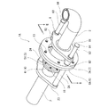
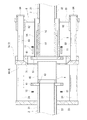
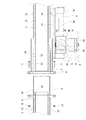
図1および図2に、本発明の第1実施形態に係る継手構造1Aを示す。継手構造1Aは、第1二重管2と第2二重管3とを接続するためのものである。
(First embodiment)
1 and 2 show a
第1二重管2は、内管21と外管22を有し、それらの間の空間が図略のポンプによって真空引きされることで真空となっている。同様に、第2二重管3は、内管31と外管32を有し、それらの間の空間が図略のポンプによって真空引きされることで真空となっている。
The first
本実施形態では、第1二重管2が構造体(図示せず)に固定されており、第2二重管3が移動可能である。ただし、第2二重管3が構造体に固定されており、第1二重管2が移動可能であってもよいし、第1二重管2と第2二重管3の双方が移動可能であってもよい。
In the present embodiment, the first
例えば、構造体は、LNGや液化水素などの液化ガス運搬船の船体である。この場合、第1二重管2は、液化ガス運搬船に搭載されたタンクから延びる供給管の一部であり、第2二重管3は、陸上に設置されたローディングアームの一部である。ただし、継手構造1Aがその他の用途に用いられてもよいことは言うまでもない。
For example, the structure is a hull of a liquefied gas carrier ship such as LNG or liquefied hydrogen. In this case, the first
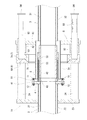
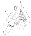
第1二重管2の端部には、雄バイオネット4が設けられており、第2二重管3の端部には、雌バイオネット5が設けられている。ただし、雄バイオネット4が第2二重管3の端部に設けられ、雌バイオネット5が第1二重管2の端部に設けられてもよい。図6は、雄バイオネット4が雌バイオネット5内へ挿入される直前の状態を示す。
A
雄バイオネット4は、第1二重管2から径方向外向きに広がる第1フランジ41と、第1フランジ41から第1二重管2の軸方向に突出する筒状体42を有している。筒状体42の内径は、第1二重管2の内管21の内径よりも大きく、筒状体42の根本部には、内管21の内径と同一の内径のリング43が設けられている。
The
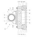
雌バイオネット5は、雄バイオネット4の第1フランジ41とボルト11およびナット12により締結される第2フランジ51を有している。第2フランジ51は、内ハウジング53および筒状体52を介して第2二重管3の内管31に結合されているとともに、外ハウジング54を介して第2二重管3の外管32に結合されている。内ハウジング53および筒状体52と外ハウジング54の間の空間は、第2二重管3の内管31と外管32の間の空間と連通しており、真空である。
The
雌バイオネット5の筒状体52は、第2二重管3の内管31の内径と同一の内径を有している。筒状体52と内ハウジング53の間には、雄バイオネット4の筒状体42が挿入される差込口が形成されている。筒状体52は、雌バイオネット5の第2フランジ51が雄バイオネット4の第1フランジ41と締結されたときに、雄バイオネット4のリング43と当接する。
The
さらに、継手構造1Aは、図1および図2に示すように、第1二重管2に取り付けられた第1位置決め部材6と、第2二重管3に取り付けられた第2位置決め部材7を含む。第2位置決め部材7は、雄バイオネット4の軸心と雌バイオネット5の軸心とが一致するように第1位置決め部材6に対して位置決めされる。
Further, the
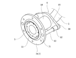
本実施形態では、第1位置決め部材6が、第1二重管2と同心の第1リング6Aであり、第2位置決め部材7が、第2二重管3と同心の第2リング7Aである。また、本実施形態では、図3に示すように、第2リング7Aの内周縁部に、第1リング6Aに向かって縮径する、第2リング7Aと同心の外向きテーパー面71が形成されている。一方、第1リング6Aの内周縁部には、図2に示すように、第2リング7Aの外向きテーパー面71と面接触する、第1リング6Aと同心の内向きテーパー面61が形成されている。ただし、外向きテーパー面71および内向きテーパー面61は、それぞれ第2リング7Aおよび第1リング6Aの外周縁部に形成されてもよい。また、第1リング6Aに第1リング6Aと同心の外向きテーパー面71が形成され、第2リング7Aに第2リング7Aと同心の内向きテーパー面61が形成されてもよい。
In the present embodiment, the
第1リング6Aは、第1二重管2の軸方向において筒状体42の先端と同じ位置に配置されている(図6参照)。換言すれば、第1リング6Aは、筒状体42の先端を取り囲んでいる。ただし、第1リング6Aは、筒状体42の先端よりも前方(第2二重管3側)に位置していてもよいし、筒状体42の先端よりも後方(第1二重管2側)に位置していてもよい。
The
一方、第1二重管2の外管22には、雄バイオネット4の第1フランジ41から離れた位置に支持プレート23が固定されている。支持プレート23は、略菱形状をなしており、その両端部に、第1二重管2の軸方向に延びる2つの支柱24が立てられている。第1リング6Aは、支柱24の先端に固定されている。つまり、第1リング6Aは、支柱24および支持プレート23を介して第1二重管2に取り付けられている。ただし、支持プレート23の形状および支柱24の本数は、適宜変更可能である。
On the other hand, a
一方、第2リング7Aは、スライド機構8を介して第2二重管3に取り付けられている。スライド機構8は、第2リング7Aを第2二重管3の軸方向にスライド可能に支持する。
On the other hand, the
具体的に、スライド機構8は、雌バイオネット5の外ハウジング54の第2フランジ51とは反対側の端部に固定された支持プレート81を含む。なお、支持プレート81は、第2二重管3の外管32に固定されてもよい。支持プレート23は、略菱形状をなしており、その両端部には2つの軸受82が設けられている。各軸受82内には、第2二重管3の軸方向に延びるシャフト83が挿通されている。第2リング7Aは、シャフト83の一端に固定されており、シャフト83の他端には抜け止め用のストッパー84が設けられている。ただし、支持プレート81の形状およびシャフト83の本数は、適宜変更可能である。
Specifically, the
第2リング7Aは、ストッパー84が軸受82に当接するまで前進可能であるとともに、第2リング7Aが軸受82に当接するまで後退可能である。第2リング7Aは、図6に示すように最も前進したときに、第2二重管3の軸方向において第2フランジ51と同じ位置に位置する。換言すれば、第2リング7Aが第2フランジ51を取り囲む。また、第2リング7Aが最も前進した状態で第2リング7Aが第1リング6Aに対して位置決めされたときには、雄バイオネット4の筒状体42の先端と雌バイオネット5の第2フランジ51との間に隙間が形成される。
The
次に、継手構造1Aを使用して第1二重管2に第2二重管3を接続する方法を説明する。
Next, a method of connecting the second
まず、図4に示すように、第2リング7Aを最も前進させる。次に、図5に示すように、第2リング7Aにおける外向きテーパー面71を有する凸部を第1リング6Aにおける内向きテーパー面61で形成される凹部内に挿入しながら、第2リング7Aを第1リング6Aに対して位置決めする。その後、第1リング6Aと第2リング7Aとをボルト13およびナット14によって締結する。
First, as shown in FIG. 4, the
第1リング6Aに対して第2リング7Aが位置決めされることによって、図6に示すように、雄バイオネット4が雌バイオネット5内へ挿入可能な状態となる。その状態で、スライド機構8を使用して第2リング7Aを第2二重管3に対してスライドさせながら第2二重管3を第1二重管2に近づけて、雄バイオネット4を雌バイオネット5内へ挿入する。その後、雄バイオネット4の第1フランジ41と雌バイオネット5の第2フランジ51とをボルト11およびナット12により締結する。
By positioning the
以上説明したように、本実施形態の継手構造1Aでは、第1リング6Aに対して第2リング7Aが位置決めされた状態で、スライド機構8を使用して、雄バイオネット4を雌バイオネット5内へ容易に挿入することができる。特に、本実施形態のように、第1二重管2が固定側であり、第2二重管3が可動側であれば、第1リング6Aに対する第2リング7Aの位置決め後は、第2二重管3を押し込むだけでよい。
As described above, in the
さらに、本実施形態では、第2リング7Aに外向きテーパー面71が形成され、第1リング6Aに内向きテーパー面61が形成されているので、外向きテーパー面71を有する凸部を内向きテーパー面61で形成される凹部内に挿入するだけで、第1リング6Aに対して第2リング7Aを位置決めすることができる。
Furthermore, in this embodiment, since the outwardly tapered
<変形例>
前記実施形態とは逆に、第2リング7Aを第2二重管3に固定し、第1リング6Aをスライド機構8を介して第1二重管2に取り付けてもよい。つまり、スライド機構8は、第1リング6Aを第1二重管2の軸方向にスライド可能に支持してもよい。
<Modification>
Contrary to the above embodiment, the
また、外向きテーパー面71および内向きテーパー面72の代わりに、第1リング6Aおよび第2リング6Bに設けられるボルト13用の貫通穴とボルト13との隙間を微小にすることによって、第1リング6Aに対して第2リング7Aを位置決めしてもよい。
In addition, instead of the
(第2実施形態)
図7〜図9に、本発明の第2実施形態に係る継手構造1Bを示す。なお、本実施形態において、第1実施形態と同一構成要素には同一符号を付し、重複した説明は省略する。
(Second Embodiment)
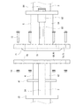
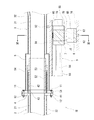
7 to 9 show a
本実施形態でも、第1実施形態と同様に、固定側の第1二重管2の端部に雄バイオネット4が設けられ、可動側の第2二重管3の端部に雌バイオネット5が設けられている。ただし、雄バイオネット4が第2二重管3の端部に設けられ、雌バイオネット5が第1二重管2の端部に設けられてもよい。
Also in the present embodiment, as in the first embodiment, the
また、本実施形態では、第1位置決め部材6が、第1二重管2が固定された構造体16を介して第1二重管2に取り付けられており、第2位置決め部材7が、スライド機構9を介して第2二重管3に取り付けられている。第1位置決め部材6は、雄バイオネット4の第1フランジ41からかなり前方(第2二重管3側)に配置されている。
Moreover, in this embodiment, the
具体的に、第1位置決め部材6は、第1二重管2の軸方向と直交する方向に延びる短冊状のベースプレート63と、このベースプレート63の両端部に固定された2つのブロック6Bを含む。ベースプレート63は、構造体16に固定されている。各ブロック6Bには、第1二重管2の軸方向およびベースプレート63の延びる方向と直交する方向に開口する嵌合穴62が設けられている。ただし、第1位置決め部材6は、2つの嵌合穴62が設けられた、第1二重管2の軸方向と直交する方向に延びる単一のバーであってもよい。
Specifically, the
一方、第2位置決め部材7は、第2二重管3の軸方向と直交する方向に延びるバー72と、バー72の両端部に固定された2つのピン7Bを含む。バー72は、第1位置決め部材6のベースプレート63と平行である。各ピン7Bは、第1位置決め部材6の対応するブロック6Bの嵌合穴62内に挿入される。各ピン7Bの先端は先細りとなっており、各嵌合穴62はピン7Bと嵌り合うように底に向かって縮径している。ただし、ピン7Bおよび嵌合穴62の数は、3つ以上であってもよい。
On the other hand, the
スライド機構9は、第2位置決め部材7を第2二重管3の軸方向にスライド可能に支持する。具体的に、スライド機構9は、第2位置決め部材7と第2二重管3との間に介在する、第2二重管3の軸方向に平行なベースプレート91を含む。ベースプレート91は、一対のブラケット92を介して、第2二重管3の外管32および雌バイオネット5の外ハウジング54に結合されている。
The
第2位置決め部材7のバー72は、第2二重管3の軸方向に延びる2つのシャフト94に貫通されている。ただし、シャフト94の本数は、適宜変更可能である。各シャフト94の両端部は、ホルダ93によってベースプレート91に固定されている。一方、バー72には、シャフト94に挿通される2つの軸受95が設けられている。
The
第2位置決め部材7は、軸受95が前方(図8では左側)のホルダ93に当接するまで前進可能であるとともに、軸受95が後方(図8では右側)のホルダ93に当接するまで後退可能である。図11に示すように、第2位置決め部材7が最も前進した状態で第2位置決め部材7が第1位置決め部材6に対して位置決めされたときには、雄バイオネット4の筒状体42の先端と雌バイオネット5の第2フランジ51との間に隙間が形成される。
The
次に、継手構造1Bを使用して第1二重管2に第2二重管3を接続する方法を説明する。
Next, a method for connecting the second
まず、図10に示すように、第2位置決め部材7を最も前進させる。次に、図11に示すように、第2位置決め部材7のピン7Bを第1位置決め部材6の嵌合穴62内に挿入することで、第2位置決め部材7を第1位置決め部材6に対して位置決めする。その後、ボルト15によって第2位置決め部材7を第1位置決め部材6に締結する。
First, as shown in FIG. 10, the
第1位置決め部材6に対して第2位置決め部材7が位置決めされることによって、雄バイオネット4が雌バイオネット5内へ挿入可能な状態となる。その状態で、スライド機構9を使用して第2位置決め部材7を第2二重管3に対してスライドさせながら第2二重管3を第1二重管2に近づけて、雄バイオネット4を雌バイオネット5内へ挿入する。その後、雄バイオネット4の第1フランジ41と雌バイオネット5の第2フランジ51とをボルト11およびナット12により締結する。
By positioning the
以上説明したように、本実施形態の継手構造1Bでは、第1位置決め部材6に対して第2位置決め部材7が位置決めされた状態で、スライド機構9を使用して、雄バイオネット4を雌バイオネット5内へ容易に挿入することができる。特に、第1二重管2が固定側であり、第2二重管3が可動側であれば、第1位置決め部材6に対する第2位置決め部材7の位置決め後は、第2二重管3を押し込むだけでよい。
As described above, in the joint structure 1 </ b> B of the present embodiment, the
<変形例>
前記実施形態とは逆に、第2位置決め部材7を第2二重管3に固定し、第1位置決め部材6をスライド機構9および構造体16を介して第1二重管2に取り付けてもよい。つまり、スライド機構9は、構造体16上で、第1位置決め部材6を第1二重管2の軸方向にスライド可能に支持してもよい。
<Modification>
Contrary to the above embodiment, the
また、前記実施形態とは逆に、第2二重管3に取り付けられる第2位置決め部材7が2つの嵌合穴62を含み、第1二重管2に取り付けられる第1位置決め部材6が2つのピン7Bを含んでもよい。
Contrary to the above embodiment, the
(その他の実施形態)
本発明は上述した実施形態に限定されるものではなく、本発明の要旨を逸脱しない範囲で種々の変形が可能である。
(Other embodiments)
The present invention is not limited to the above-described embodiments, and various modifications can be made without departing from the gist of the present invention.
例えば、雄バイオネット4および雌バイオネット5の構造は、図6に示すものに限らず、種々の構造が採用可能である。
For example, the structures of the
1A,1B 継手構造
2 第1二重管
3 第2二重管
4 雄バイオネット
41 第1フランジ
5 雌バイオネット
51 第2フランジ
6 第1位置決め部材
6A 第1リング
62 嵌合穴
7 第2位置決め部材
7A 第2リング
7B ピン
8,9 スライド機構
1A,
Claims (5)
前記第1二重管と前記第2二重管の一方の端部に設けられた、第1フランジを有する雄バイオネットと、
前記第1二重管と前記第2二重管の他方の端部に設けられた、前記第1フランジと締結される第2フランジを有する雌バイオネットと、
前記第1二重管に取り付けられた第1位置決め部材と、
前記第2二重管に取り付けられた、前記雄バイオネットの軸心と前記雌バイオネットの軸心とが一致するように前記第1位置決め部材に対して位置決めされる第2位置決め部材と、
前記第1位置決め部材を前記第1二重管の軸方向にスライド可能に支持する、または前記第2位置決め部材を前記第2二重管の軸方向にスライド可能に支持するスライド機構と、
を備える、継手構造。 A joint structure for connecting the first double pipe and the second double pipe,
A male bayonet having a first flange provided at one end of the first double pipe and the second double pipe;
A female bayonet having a second flange fastened to the first flange, provided at the other end of the first double pipe and the second double pipe;
A first positioning member attached to the first double pipe;
A second positioning member attached to the second double pipe and positioned with respect to the first positioning member so that an axis of the male bayonet and an axis of the female bayonet coincide with each other;
A slide mechanism for supporting the first positioning member so as to be slidable in the axial direction of the first double pipe, or for supporting the second positioning member so as to be slidable in the axial direction of the second double pipe;
A joint structure comprising:
前記第2位置決め部材は、前記第2二重管と同心の第2リングである、請求項1または2に記載の継手構造。 The first positioning member is a first ring concentric with the first double pipe;
The joint structure according to claim 1 or 2, wherein the second positioning member is a second ring concentric with the second double pipe.
前記第2位置決め部材は、前記複数の嵌合穴内にそれぞれ挿入される複数のピンを含む、請求項1または2に記載の継手構造。 The first positioning member includes a plurality of fitting holes that open in a direction orthogonal to the axial direction of the first double pipe,
The joint structure according to claim 1, wherein the second positioning member includes a plurality of pins respectively inserted into the plurality of fitting holes.
Priority Applications (6)
| Application Number | Priority Date | Filing Date | Title |
|---|---|---|---|
| JP2016078607A JP6803148B2 (en) | 2016-04-11 | 2016-04-11 | Joint structure |
| EP17782343.2A EP3444516B1 (en) | 2016-04-11 | 2017-04-10 | Joint structure |
| CN201780022656.5A CN108884958B (en) | 2016-04-11 | 2017-04-10 | Joint structure |
| AU2017250982A AU2017250982B2 (en) | 2016-04-11 | 2017-04-10 | Joint structure |
| PCT/JP2017/014652 WO2017179530A1 (en) | 2016-04-11 | 2017-04-10 | Coupling structure |
| US16/093,137 US11248726B2 (en) | 2016-04-11 | 2017-04-10 | Joint structure |
Applications Claiming Priority (1)
| Application Number | Priority Date | Filing Date | Title |
|---|---|---|---|
| JP2016078607A JP6803148B2 (en) | 2016-04-11 | 2016-04-11 | Joint structure |
Publications (2)
| Publication Number | Publication Date |
|---|---|
| JP2017190784A true JP2017190784A (en) | 2017-10-19 |
| JP6803148B2 JP6803148B2 (en) | 2020-12-23 |
Family
ID=60042192
Family Applications (1)
| Application Number | Title | Priority Date | Filing Date |
|---|---|---|---|
| JP2016078607A Active JP6803148B2 (en) | 2016-04-11 | 2016-04-11 | Joint structure |
Country Status (6)
| Country | Link |
|---|---|
| US (1) | US11248726B2 (en) |
| EP (1) | EP3444516B1 (en) |
| JP (1) | JP6803148B2 (en) |
| CN (1) | CN108884958B (en) |
| AU (1) | AU2017250982B2 (en) |
| WO (1) | WO2017179530A1 (en) |
Cited By (3)
| Publication number | Priority date | Publication date | Assignee | Title |
|---|---|---|---|---|
| JP2020095007A (en) * | 2018-12-13 | 2020-06-18 | 瑞六 王 | Flange protective structure including detection and warning, and pipeline joint leakage prevention device |
| JP2020138579A (en) * | 2019-02-27 | 2020-09-03 | 大陽日酸株式会社 | Space environment test equipment |
| JP2023136550A (en) * | 2022-03-17 | 2023-09-29 | 岩谷産業株式会社 | Connection joint structure |
Families Citing this family (3)
| Publication number | Priority date | Publication date | Assignee | Title |
|---|---|---|---|---|
| US11047517B2 (en) * | 2018-10-31 | 2021-06-29 | Praxair Technology, Inc. | Modular vacuum insulated piping |
| EP3670999A1 (en) * | 2018-12-20 | 2020-06-24 | Nexans | Johnston coupling with displacement unit |
| EP3842681B1 (en) * | 2019-12-26 | 2022-11-09 | Nexans | Quick release johnston plug-in coupling |
Family Cites Families (17)
| Publication number | Priority date | Publication date | Assignee | Title |
|---|---|---|---|---|
| US3151355A (en) * | 1963-01-14 | 1964-10-06 | Justin H Ramsey | Splice box |
| US4330140A (en) * | 1977-04-01 | 1982-05-18 | Smith International, Inc. | Marine riser connector |
| CA1283528C (en) * | 1985-10-16 | 1991-04-30 | Michael Johannes Landman | Apparatus for replacing pipe gaskets |
| JPS63101594A (en) * | 1986-10-15 | 1988-05-06 | 株式会社日立製作所 | Bayonet fitting for cryogenic piping |
| CN1023251C (en) * | 1990-06-30 | 1993-12-22 | 约翰逊公司 | Air-controlled rotary joint |
| NL9002816A (en) * | 1990-12-19 | 1992-07-16 | Single Buoy Moorings | QUICK COUPLING AND QUICK COUPLING ASSEMBLY. |
| JP3338931B2 (en) * | 1999-05-17 | 2002-10-28 | 住友重機械工業株式会社 | Bayonet fitting for cryogenic fluid |
| US6290434B1 (en) * | 1999-12-30 | 2001-09-18 | Hylsa, S.A. De C.V. | Expansion joint for high-pressure high-temperature pneumatic transport of DRI or other abrasive particles |
| JP2002005378A (en) * | 2000-06-23 | 2002-01-09 | Ishikawajima Harima Heavy Ind Co Ltd | Cryogenic piping coupling device |
| US6467811B2 (en) * | 2000-08-10 | 2002-10-22 | Omega Multi National | Flanged connection repair device and method |
| WO2004106696A1 (en) * | 2003-05-28 | 2004-12-09 | Vetco Aibel As | A spool piece termination structure, a connection arrangement comprising such a termination structure and a pipeline termination |
| JP5415090B2 (en) | 2009-01-22 | 2014-02-12 | 川崎重工業株式会社 | Vacuum insulated piping for low-temperature liquefied gas |
| JP2013002502A (en) * | 2011-06-14 | 2013-01-07 | Nifco Inc | Pipe joint and pipe joint connection system |
| CN202580387U (en) * | 2012-05-15 | 2012-12-05 | 青岛瑞丰气体有限公司 | Connecting flange with vacuum tube |
| EP2722480B1 (en) * | 2012-10-17 | 2016-04-20 | Vetco Gray Scandinavia AS | Connection appliance and connection arrangement comprising such a connection appliance |
| CN104251367B (en) * | 2014-08-18 | 2016-03-30 | 中国科学院高能物理研究所 | A vacuum isolation device for ultra-low temperature fluid transmission pipeline |
| JP2016070376A (en) * | 2014-09-30 | 2016-05-09 | 川崎重工業株式会社 | Guide mechanism for bayonet joints of vacuum heat insulation double pipe for cryogenic fluid |
-
2016
- 2016-04-11 JP JP2016078607A patent/JP6803148B2/en active Active
-
2017
- 2017-04-10 AU AU2017250982A patent/AU2017250982B2/en active Active
- 2017-04-10 WO PCT/JP2017/014652 patent/WO2017179530A1/en not_active Ceased
- 2017-04-10 US US16/093,137 patent/US11248726B2/en active Active
- 2017-04-10 EP EP17782343.2A patent/EP3444516B1/en active Active
- 2017-04-10 CN CN201780022656.5A patent/CN108884958B/en active Active
Cited By (4)
| Publication number | Priority date | Publication date | Assignee | Title |
|---|---|---|---|---|
| JP2020095007A (en) * | 2018-12-13 | 2020-06-18 | 瑞六 王 | Flange protective structure including detection and warning, and pipeline joint leakage prevention device |
| JP2020138579A (en) * | 2019-02-27 | 2020-09-03 | 大陽日酸株式会社 | Space environment test equipment |
| JP2023136550A (en) * | 2022-03-17 | 2023-09-29 | 岩谷産業株式会社 | Connection joint structure |
| JP7553033B2 (en) | 2022-03-17 | 2024-09-18 | 岩谷産業株式会社 | Connection joint structure |
Also Published As
| Publication number | Publication date |
|---|---|
| EP3444516A4 (en) | 2019-11-13 |
| CN108884958B (en) | 2021-01-05 |
| CN108884958A (en) | 2018-11-23 |
| WO2017179530A1 (en) | 2017-10-19 |
| US11248726B2 (en) | 2022-02-15 |
| AU2017250982A1 (en) | 2018-11-29 |
| JP6803148B2 (en) | 2020-12-23 |
| EP3444516B1 (en) | 2021-03-17 |
| AU2017250982B2 (en) | 2019-07-25 |
| EP3444516A1 (en) | 2019-02-20 |
| US20190331268A1 (en) | 2019-10-31 |
Similar Documents
| Publication | Publication Date | Title |
|---|---|---|
| JP2017190784A (en) | Joint structure | |
| CN105081669A (en) | Pipe centering assembly platform | |
| CN108138940B (en) | Apparatus for mounting rings of planetary gear trains | |
| CN210860138U (en) | Double wall tube structure | |
| WO2010021807A3 (en) | Fuel injector sans support/stem | |
| CN106885084A (en) | For the polylinker manifold of snap joint | |
| CN105697884A (en) | Multi-pipe-diameter automobile air conditioner pipeline clamp | |
| JP6447970B2 (en) | Hose automatic fastening device | |
| JP2017202783A (en) | Connection structure between vessel and loading arm | |
| TWI516333B (en) | Jig assembly for machining | |
| CL2018000029A1 (en) | Shell and tube equipment with anti-vibration baffles. | |
| CN204867796U (en) | Heavy -calibre thin cylinder butt welding assembly clamping device | |
| JP2010500505A5 (en) | ||
| CN109422017A (en) | Vacuum insulated vessel | |
| CN104738002A (en) | A fishing rod supporting device, a fishing rod keeping barrel fixing tool and a supplementary fishing rod keeping barrel | |
| CN201437188U (en) | Deep pipe internal welding device | |
| BRPI0503162A (en) | device for performing a synchronized relative rotation between a mechanical component and tools for processing it about eccentric axes | |
| CN105650387A (en) | Quick pipeline joint | |
| JP3210495U (en) | Arbor thermal expansion holder | |
| JP6654801B2 (en) | Pipe fittings | |
| TW201031477A (en) | Quick release through core device of a pipe bending machine | |
| JP2015155133A (en) | Assembly device of filler pipe | |
| CN202580405U (en) | Fluid rapid connector with loosened central axis alignment requirement | |
| JP2005069369A (en) | Stop ring and fluid equipment with stop ring | |
| JP6639096B2 (en) | Joint nut and joint structure |
Legal Events
| Date | Code | Title | Description |
|---|---|---|---|
| A621 | Written request for application examination |
Free format text: JAPANESE INTERMEDIATE CODE: A621 Effective date: 20190325 |
|
| A131 | Notification of reasons for refusal |
Free format text: JAPANESE INTERMEDIATE CODE: A131 Effective date: 20200310 |
|
| A601 | Written request for extension of time |
Free format text: JAPANESE INTERMEDIATE CODE: A601 Effective date: 20200427 |
|
| A521 | Request for written amendment filed |
Free format text: JAPANESE INTERMEDIATE CODE: A523 Effective date: 20200703 |
|
| TRDD | Decision of grant or rejection written | ||
| A01 | Written decision to grant a patent or to grant a registration (utility model) |
Free format text: JAPANESE INTERMEDIATE CODE: A01 Effective date: 20201104 |
|
| A61 | First payment of annual fees (during grant procedure) |
Free format text: JAPANESE INTERMEDIATE CODE: A61 Effective date: 20201130 |
|
| R150 | Certificate of patent or registration of utility model |
Ref document number: 6803148 Country of ref document: JP Free format text: JAPANESE INTERMEDIATE CODE: R150 |
|
| R250 | Receipt of annual fees |
Free format text: JAPANESE INTERMEDIATE CODE: R250 |
|
| R250 | Receipt of annual fees |
Free format text: JAPANESE INTERMEDIATE CODE: R250 |
|
| R250 | Receipt of annual fees |
Free format text: JAPANESE INTERMEDIATE CODE: R250 |