JP2017190767A - Knocking detection device of internal combustion engine - Google Patents
Knocking detection device of internal combustion engine Download PDFInfo
- Publication number
- JP2017190767A JP2017190767A JP2016082487A JP2016082487A JP2017190767A JP 2017190767 A JP2017190767 A JP 2017190767A JP 2016082487 A JP2016082487 A JP 2016082487A JP 2016082487 A JP2016082487 A JP 2016082487A JP 2017190767 A JP2017190767 A JP 2017190767A
- Authority
- JP
- Japan
- Prior art keywords
- noise
- dimensional map
- knocking
- map
- data
- Prior art date
- Legal status (The legal status is an assumption and is not a legal conclusion. Google has not performed a legal analysis and makes no representation as to the accuracy of the status listed.)
- Pending
Links
Images


Abstract
Description
本発明は、内燃機関のノッキング検出装置に関し、特にノッキングセンサの出力信号に含まれる周波数成分の強度の時系列データに基づいてノッキングの発生を判定するものに関する。 The present invention relates to a knocking detection device for an internal combustion engine, and more particularly to a device for determining occurrence of knocking based on time-series data of the intensity of a frequency component included in an output signal of a knocking sensor.
特許文献1には、ノッキングセンサの出力信号に含まれる周波数成分強度の時系列データに基づいてノッキングの発生を判定するノッキング検出装置が示されている。この装置によれば、複数の周波数成分強度の時系列データが、クランク角度位置及び周波数で定義される2次元マップとして格納されるとともに、周波数成分強度の時系列データが二値化され、二値化された時系列データの2次元マップと、ノッキングが発生した状態に対応するマスタパターンデータの2次元マップとを比較することより、ノッキングが発生したか否かが判定される。
ノッキングセンサの出力信号には、吸気弁の着座時に発生するノイズなどのノイズ成分が含まれているため、特許文献1に示された装置では、ノイズ成分強度を算出して、周波数成分強度の時系列データをノイズ成分強度によって補正する処理、及び二値化された時系列データの2次元マップと、マスタパターンデータの2次元マップとの適合率を算出し、適合率が判定閾値を超えるとノッキングが発生したと判定する処理が行われる。
Since the output signal of the knocking sensor includes a noise component such as noise generated when the intake valve is seated, the device disclosed in
しかしながら、気筒数や気筒配置などで代表される機関の構造やノックセンサの装着位置などに依存して、クランク角度位置及び周波数で定義される2次元マップにおけるノイズ成分強度の分布が変化し、さらに気筒毎にノイズ成分強度が変化することがあり、そのようなノイズ成分強度の変化によってノッキングの判定精度が低下する場合があることが確認されている。 However, depending on the engine structure represented by the number of cylinders and the cylinder arrangement, the position where the knock sensor is mounted, etc., the distribution of the noise component intensity in the two-dimensional map defined by the crank angle position and frequency changes. It has been confirmed that the noise component strength may vary from cylinder to cylinder, and that the knocking determination accuracy may be reduced due to such a change in the noise component strength.
本発明はこの点に着目してなされたものであり、ノッキングの判定に適用する周波数成分強度の時系列データをノイズの発生状態に応じて修正するとともに、上記適合率の判定閾値を適切に設定し、ノッキング判定精度を高めることができるノッキング検出装置を提供することを目的とする。 The present invention has been made paying attention to this point, and corrects the time-series data of the frequency component intensity applied to the determination of knocking according to the state of occurrence of noise, and appropriately sets the threshold value for determining the precision. And it aims at providing the knocking detection apparatus which can raise a knocking determination precision.
上記目的を達成するため請求項1に記載の発明は、複数の気筒を備える内燃機関に装着されたノックセンサ(11R,11L)の出力信号に基づいてノッキングを検出する、内燃機関のノッキング検出装置において、所定クランク角度間隔で前記ノックセンサ出力信号の周波数成分分析を行う周波数成分分析手段と、前記周波数成分分析により得られる、複数の周波数成分の強度の時系列データ(STFT(i,j))を、クランク角度位置(i)及び周波数(j)で定義される2次元マップとして格納するデータ格納手段と、前記周波数成分強度の時系列データ(STFT(i,j))に基づいて、ノイズ成分強度の時系列データ(SNOISE(i,j,k))を算出するノイズ成分強度算出手段と、前記2次元マップに格納された周波数成分強度(STFT(i,j))と、対応するノイズ成分強度(SNOISE(i,j,k))との差分をノイズ差分(DSNOISE(i,j))として算出するノイズ差分算出手段と、前記ノイズ差分(DSNOISE(i,j))に応じて前記2次元マップを修正することにより、修正2次元マップを生成する2次元マップ修正手段と、前記修正2次元マップの時系列データを前記ノイズ成分強度の時系列データ(SNOISE(i,j,k)により補正するノイズ補正手段と、前記ノイズ補正手段による補正後の時系列データ(STFTC(i,j))を、前記機関の運転状態に応じて設定される二値化閾値(STJUD(i,j,k)を用いて二値化する二値化手段と、前記二値化された時系列データ(BSTFT(i,j))の2次元マップと、ノッキングが発生した状態に対応するマスタパターンデータ(BMST(i,j))の2次元マップとの適合率(PFIT)を算出し、算出した適合率が適合率閾値(PFITTH(kX))を超えたときに、ノッキングが発生したと判定するノッキング判定手段とを備え、前記ノッキング判定手段は、前記2次元マップ修正手段による修正度合(NMOD)が大きくなるほど前記適合率閾値(PFITTH(kX))が減少するように、前記適合率閾値(PFITTH(kX))を設定することを特徴とする。
In order to achieve the above object, an invention according to
この構成によれば、所定クランク角度間隔でノックセンサ出力信号の周波数成分分析が行われ、その周波数成分分析により得られる、複数の周波数成分の強度の時系列データが、クランク角度位置及び周波数で定義される2次元マップとして格納される。周波数成分強度の時系列データに基づいて、ノイズ成分強度の時系列データが気筒毎に算出され、2次元マップに格納された周波数成分強度と、対応するノイズ成分強度との差分がノイズ差分として算出される。このノイズ差分に応じて2次元マップを修正することにより、修正2次元マップが生成され、修正2次元マップの時系列データがノイズ成分強度の時系列データにより補正される。補正後の時系列データが二値化閾値を用いて二値化され、その二値化された時系列データの2次元マップと、ノッキングが発生した状態に対応するマスタパターンデータの2次元マップとの適合率が算出され、その適合率が適合率閾値を超えたときに、ノッキングが発生したと判定され、修正2次元マップの修正度合が大きくなるほど適合率閾値が減少するように、適合率閾値が設定される。 According to this configuration, the frequency component analysis of the knock sensor output signal is performed at a predetermined crank angle interval, and the time series data of the intensity of a plurality of frequency components obtained by the frequency component analysis is defined by the crank angle position and the frequency. Stored as a two-dimensional map. Based on the time-series data of the frequency component intensity, the time-series data of the noise component intensity is calculated for each cylinder, and the difference between the frequency component intensity stored in the two-dimensional map and the corresponding noise component intensity is calculated as the noise difference. Is done. By correcting the two-dimensional map according to the noise difference, a corrected two-dimensional map is generated, and the time series data of the corrected two-dimensional map is corrected with the time series data of the noise component intensity. The corrected time series data is binarized using a binarization threshold, the two-dimensional map of the binarized time series data, and the two-dimensional map of the master pattern data corresponding to the state where knocking occurs The precision ratio threshold is calculated such that when the precision ratio is calculated and the precision ratio exceeds the precision ratio threshold value, it is determined that knocking has occurred, and the precision threshold value decreases as the correction degree of the corrected two-dimensional map increases. Is set.
機関の構造あるいはノックセンサの装着位置に依存して、機関運転状態の変化がノイズ成分強度に与える影響が、気筒毎に異なる場合や、ノイズ成分の周波数帯域や出現時期に依存して変化する場合があるので、複数気筒のそれぞれに対応したノイズ成分強度の算出を行い、ノイズ差分を算出することによって実際のノイズ発生状態を気筒毎にかつ2次元マップの格子点毎に監視し、ノイズ差分に応じて周波数成分強度の2次元マップを修正することにより、ノイズ成分強度の大きい気筒あるいは2次元マップの格子点において、周波数成分強度を修正して、ノイズ成分の影響が大きい周波数成分強度を除いた修正2次元マップを生成し、ノイズ成分の影響を低減することが可能となる。ただし、修正2次元マップには検出された周波成分強度ではない修正データが含まれることとなるため、修正度合に応じて適合率閾値を減少させることによって、ノイズ成分の影響を低減してノッキング判定精度を高めることができる。 Depending on the engine structure or knock sensor mounting position, the effect of changes in engine operating conditions on the noise component intensity varies from cylinder to cylinder, or changes depending on the frequency band and appearance time of the noise component Therefore, the noise component intensity corresponding to each of the cylinders is calculated, and the noise difference is calculated to monitor the actual noise generation state for each cylinder and for each grid point of the two-dimensional map. Accordingly, by correcting the two-dimensional map of the frequency component intensity, the frequency component intensity is corrected in the cylinder having the large noise component intensity or the lattice point of the two-dimensional map, and the frequency component intensity having a large influence of the noise component is removed. It is possible to generate a modified two-dimensional map and reduce the influence of noise components. However, since the correction two-dimensional map includes correction data that is not the detected frequency component intensity, knocking determination is made by reducing the influence of the noise component by reducing the precision threshold value according to the correction degree. Accuracy can be increased.
請求項2に記載の発明は、請求項1に記載の内燃機関のノッキング検出装置において、前記2次元マップ修正手段は、前記2次元マップ上の、ノイズ成分の影響が大きい特定領域(例えば、i=1,j=1〜16の領域)において、前記周波数成分強度(STFT(i,j))の修正を行うことを特徴とする。 According to a second aspect of the present invention, in the knock detection device for an internal combustion engine according to the first aspect, the two-dimensional map correction means is a specific region (for example, i) on the two-dimensional map where the influence of noise components is large. = 1, j = 1 to 16), the frequency component intensity (STFT (i, j)) is corrected.
この構成によれば、2次元マップ上の特定領域において周波数成分強度の修正が行われる。ノイズ成分の影響が大きい2次元マップ上の特定領域は予め設定可能であり、その特定領域に限定して周波数成分強度の修正を行うことにより、修正2次元マップによる判定の精度が低下することを防止できる。 According to this configuration, the frequency component intensity is corrected in a specific region on the two-dimensional map. The specific area on the two-dimensional map where the influence of the noise component is large can be set in advance, and the accuracy of determination by the corrected two-dimensional map is reduced by correcting the frequency component intensity only in the specific area. Can be prevented.
請求項3に記載の発明は、請求項1または2に記載の内燃機関のノッキング検出装置において、前記2次元マップ修正手段は、前記ノイズ差分(DNOISE(i,j))が予め設定されたノイズ差分閾値(DSNTH(i,j))以上であるときは、前記周波数成分強度(STFT(i,j))を減少方向に修正することにより前記修正2次元マップを生成し、前記修正度合は、修正されたデータ数(NMOD)で示されることを特徴とする。 According to a third aspect of the present invention, in the knock detection device for the internal combustion engine according to the first or second aspect, the two-dimensional map correcting means is a noise in which the noise difference (DNOISE (i, j)) is preset. When the difference threshold (DSNTH (i, j)) or more is generated, the modified two-dimensional map is generated by correcting the frequency component intensity (STFT (i, j)) in a decreasing direction, and the degree of correction is It is indicated by the corrected number of data (NMOD).
この構成によれば、ノイズ差分が予め設定されたノイズ差分閾値より大きいときは、対応する周波数成分強度を減少方向に修正することにより修正2次元マップが生成され、修正度合は修正されたデータ数で示される。ノイズ成分の影響が大きい2次元マップ上の周波数成分強度を減少方向に修正することによって、ノイズ成分の影響を低減し、判定精度の低下を防止できる。また修正度合を修正されたデータ数で示すことによって、修正度合に応じた適合率閾値の変更を容易かつ適切に行うことができる。 According to this configuration, when the noise difference is larger than a preset noise difference threshold, a correction two-dimensional map is generated by correcting the corresponding frequency component intensity in a decreasing direction, and the correction degree is the number of corrected data. Indicated by By correcting the frequency component intensity on the two-dimensional map in which the influence of the noise component is large in the decreasing direction, the influence of the noise component can be reduced and the determination accuracy can be prevented from being lowered. In addition, by indicating the correction degree by the number of corrected data, it is possible to easily and appropriately change the precision ratio threshold according to the correction degree.
請求項4に記載の発明は、請求項1から3の何れか1項に記載の内燃機関のノッキング検出装置において、前記2次元マップ修正手段は、前記機関が、前記ノイズ成分強度が増加する特定運転状態にあるときに、前記2次元マップの修正を行い、前記機関が前記特定運転状態以外の運転状態にあるときは、前記修正を行わないことを特徴とする。 According to a fourth aspect of the present invention, in the knock detection device for an internal combustion engine according to any one of the first to third aspects, the two-dimensional map correcting means is configured to specify that the noise component intensity increases. The two-dimensional map is corrected when the engine is in an operating state, and the correction is not performed when the engine is in an operating state other than the specific operating state.
この構成によれば、機関が、ノイズ成分強度が増加する特定運転状態にあるときに、2次元マップの修正が行われ、機関が特定運転状態以外の運転状態にあるときは、2次元マップの修正が行われないので、修正2次元マップによる判定は必要最小限の運転状態に限定され、特定運転状態以外の運転状態における判定精度に影響を与えないようにすることができる。 According to this configuration, the two-dimensional map is corrected when the engine is in a specific operation state in which the noise component intensity increases, and when the engine is in an operation state other than the specific operation state, Since the correction is not performed, the determination based on the corrected two-dimensional map is limited to the minimum necessary operation state, and the determination accuracy in the operation state other than the specific operation state can be prevented from being affected.
以下本発明の実施の形態を図面を参照して説明する。
[第1の実施形態]
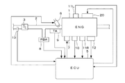
図1は、本発明の一実施形態にかかる内燃機関(以下「エンジン」という)及びその制御装置の構成を示す図であり、エンジン1は例えばV型6気筒の過給機(図示せず)を備えるエンジンである。エンジン1の吸気通路2にはスロットル弁3が設けられている。エンジン1とスロットル弁3との間かつ吸気通路2の図示しない吸気弁の少し上流側には、燃料噴射弁6が各気筒毎に設けられており、燃料噴射弁6は電子制御ユニット(以下「ECU」という)5によってその作動が制御される。エンジン1の各気筒には、点火プラグ7が設けられており、点火プラグ7にはECU5から点火信号が供給される。
Embodiments of the present invention will be described below with reference to the drawings.
[First Embodiment]
FIG. 1 is a diagram showing a configuration of an internal combustion engine (hereinafter referred to as “engine”) and a control device thereof according to an embodiment of the present invention. The
スロットル弁3の下流側には吸気圧PBAを検出する吸気圧センサ8、及び吸気温TAを検出する吸気温センサ9が設けられている。エンジン1の本体には、エンジン冷却水温TWを検出する冷却水温センサ10及び非共振型のノックセンサ11R,11Lが装着されている。ノックセンサ11Rは、#1〜#3気筒が配置された第1バンクに装着され、ノックセンサ11Lは、#4〜#6気筒が配置された第2バンクに装着されている。ノックセンサ11Rは#1〜#3気筒におけるノッキングの検出に使用され、ノックセンサ11Lは#4〜#5気筒におけるノッキングの検出に使用される。ノックセンサ11R,11Lとしては、例えば5kHzから25kHzまでの周波数帯域の振動を検出可能なものが使用される。吸気通路2のスロットル弁3の上流側には、吸入空気流量GAを検出する吸入空気流量センサ13が設けられている。
An
エンジン1のクランク軸及びカム軸(図示せず)には、それらの回転角度を検出する角度位置センサ12が設けられている。角度位置センサ12は、エンジン1の特定の気筒の所定クランク角度位置でパルス(以下「CYLパルス」という)を出力する気筒判別センサ、各気筒の吸入行程開始時の上死点(TDC)に関し所定クランク角度前のクランク角度位置で(6気筒エンジンではクランク角120度毎に)TDCパルスを出力するTDCセンサ及びTDCパルスより短い一定クランク角周期(例えば6度周期)で1パルス(以下「CRKパルス」という)を発生するCRKセンサから成り、CYLパルス、TDCパルス及びCRKパルスがECU5に供給される。これらのパルスは、燃料噴射時期、点火時期等の各種タイミング制御、エンジン回転数(エンジン回転速度)NEの検出に使用される。
An
エンジン1は、吸気弁の弁リフト量及び開角(開弁期間)を変更する第1弁作動特性可変機構と、吸気弁を駆動するカムの、クランク軸回転角度を基準とした作動位相を連続的に変更する第2弁作動特性可変機構とを有する弁作動特性可変装置20を備えている。
The
上述した各種センサ及び図示しない他のセンサ(スロットル弁の開度を検出するスロットル弁開度センサ、エンジン1によって駆動される車両のアクセルペダルの操作量を検出するアクセルセンサ、当該車両の車速を検出する車速センサなど)は、ECU5に接続されており、ECU5は、各種センサの検出信号に基づいて、燃料噴射弁6及び点火プラグ7の駆動制御、弁作動特性可変装置20の制御を行うとともに、ノックセンサ11R、11Lの出力信号に基づくノッキング検出を行う。
Various sensors described above and other sensors (not shown) (a throttle valve opening sensor for detecting the opening of the throttle valve, an accelerator sensor for detecting an operation amount of an accelerator pedal of a vehicle driven by the
本実施形態では、ノックセンサ11R,11Lの出力信号を、CRKパルスの発生毎にサンプリング周期20マイクロ秒でサンプリングして周波数成分分析を行い、その分析の結果得られる周波数成分強度の時系列データに基づいてノッキング判定を行う。このノッキング判定の手法は、特許文献1に示された手法を改良したものに相当する。
In the present embodiment, the output signals of
特許文献1に示されたノッキング判定手法(以下「基本判定手法」という)は、以下のステップを含むものである。
1)ノックセンサ出力信号の周波数成分分析を、CRKパルスの発生に同期して実行し、この周波数成分分析によって得られる、複数の周波数成分の強度の時系列データを、クランク角度位置及び周波数で定義される2次元マップとして格納し(以下この2次元マップを「検出強度マップ」といい、このマップ上のデータを「検出強度マップデータ」という)、
The knocking determination method (hereinafter referred to as “basic determination method”) disclosed in
1) The frequency component analysis of the knock sensor output signal is executed in synchronization with the generation of the CRK pulse, and the time-series data of the intensity of a plurality of frequency components obtained by this frequency component analysis is defined by the crank angle position and the frequency. Stored as a two-dimensional map (hereinafter this two-dimensional map is referred to as “detected intensity map”, and the data on this map is referred to as “detected intensity map data”),
2)ノッキングが発生していないと判定されたときの周波数成分強度の時系列データを、平均化することによってノイズ成分強度の時系列データを算出し(以下この時系列データを格納した2次元マップを「ノイズ成分強度マップ」といい、このマップ上のデータを「ノイズ成分強度マップデータ」という)、 2) The time series data of the noise component intensity is calculated by averaging the time series data of the frequency component intensity when it is determined that knocking has not occurred (hereinafter referred to as a two-dimensional map storing the time series data). Is called “noise component intensity map”, and the data on this map is called “noise component intensity map data”),
3)検出強度マップデータから、対応するノイズ成分強度マップデータを減算することによって、ノイズ成分の影響を除いた補正周波数成分強度の時系列データを算出し(以下この時系列データを格納した2次元マップを「ノイズ補正マップ」といい、このマップ上のデータを「ノイズ補正マップデータ」という)、 3) By subtracting the corresponding noise component intensity map data from the detected intensity map data, time series data of the corrected frequency component intensity excluding the influence of the noise component is calculated (hereinafter referred to as the two-dimensional data storing the time series data). The map is called "Noise correction map", and the data on this map is called "Noise correction map data"),
4)ノイズ補正マップデータを、二値化閾値を用いて二値化することにより、二値化時系列データを算出し(以下この時系列データを格納した2次元マップを「二値化マップ」といい、このマップ上のデータを「二値化マップデータ」という)、 4) The binarization time series data is calculated by binarizing the noise correction map data using the binarization threshold (hereinafter, the two-dimensional map storing the time series data is referred to as a “binarization map”. The data on this map is called "binarized map data"),
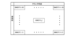
5)二値化マップと、ノッキングが発生した状態に対応するマスタパターンデータの2次元マップ(マップ上の格子点には「0」または「1」が設定されているマップであり、以下この2次元マップを「マスタマップ」といい、このマップ上のデータを「マスタマップデータ」という)との適合率を算出し、算出した適合率が適合率閾値を超えたときに、ノッキングが発生したと判定する。 5) A binarized map and a two-dimensional map of master pattern data corresponding to the state in which knocking has occurred (a map in which “0” or “1” is set at a grid point on the map; Dimensional map is called “master map”, and the data on this map is called “master map data”), and knocking occurs when the calculated precision exceeds the precision threshold. judge.
図2は、この基本判定手法の課題を説明するための図であり、ノッキングが発生していない状態において周波数成分分析によって得られる周波数成分強度の最大値STFTMAXと、エンジン回転数NEとの関係を示す。すなわち、最大値STFTMAXは、ノッキングによって発生する特有の周波数成分強度以外のノイズ成分強度の最大値に相当する。この図において実線で示す特性は、エンジン1の特定気筒(例えば#5気筒)に対応し、破線で示す特性は特定気筒以外の気筒に対応する。このようにエンジン1の高回転運転状態で特定気筒の燃焼行程におけるノイズ成分強度が増加することが確認され、このエンジン1におけるノッキング判定に基本判定手法をそのまま適用すると、高回転運転状態で特定気筒におけるノッキングの判定精度が低下するという課題がある。なお、エンジン1の高負荷運転状態においても特定気筒の燃焼行程におけるノイズ成分強度が増加する点も確認されている。
FIG. 2 is a diagram for explaining the problem of this basic determination method, and shows the relationship between the maximum value STFTMAX of the frequency component intensity obtained by the frequency component analysis and the engine speed NE when knocking has not occurred. Show. That is, the maximum value STFTMAX corresponds to the maximum value of the noise component strength other than the specific frequency component strength generated by knocking. In this figure, the characteristic indicated by a solid line corresponds to a specific cylinder (for example, # 5 cylinder) of the
この課題を解決するため本実施形態では、以下のような改良を行った。
1)基本判定手法では、ノイズ成分強度マップは全気筒共通の単一マップであるが、本実施形態では、複数気筒のそれぞれに対応したノイズ成分強度マップを設けることとした。
In order to solve this problem, the present embodiment has been improved as follows.
1) In the basic determination method, the noise component intensity map is a single map common to all cylinders, but in this embodiment, a noise component intensity map corresponding to each of a plurality of cylinders is provided.
2)基本判定手法では、二値化閾値はエンジン運転状態に応じて設定され、全気筒に共通の値が適用されるが、本実施形態では複数気筒のそれぞれに対応した二値化閾値を適用することとした。 2) In the basic determination method, the binarization threshold is set according to the engine operating state, and a common value is applied to all cylinders. In this embodiment, the binarization threshold corresponding to each of a plurality of cylinders is applied. It was decided to.
3)基本判定手法では、ノイズ補正マップデータは単一の二値化閾値を用いて二値化されるが、本実施形態ではノイズ補正マップの各格子点に対応して設定された二値化閾値を適用することとした。 3) In the basic determination method, the noise correction map data is binarized using a single binarization threshold value. In this embodiment, binarization is set corresponding to each grid point of the noise correction map. A threshold was applied.
4)基本判定手法では、検出強度マップデータからノイズ成分強度マップデータを減算することにより、ノイズ補正マップデータが算出されるが、本実施形態ではエンジン回転数NEが急変したときに、ノイズ成分強度マップデータを補正して検出強度マップデータから減算することとした。 4) In the basic determination method, the noise correction map data is calculated by subtracting the noise component intensity map data from the detected intensity map data. However, in this embodiment, when the engine speed NE suddenly changes, the noise component intensity is calculated. The map data was corrected and subtracted from the detected intensity map data.
エンジン1では高回転運転状態及び高負荷運転状態で特定気筒のノイズ成分強度が増加する傾向が確認されたが、より一般的にはエンジン1の構造あるいはノックセンサ11R,11Lの装着位置に依存して、エンジン運転状態の変化がノイズ成分強度に与える影響が、気筒毎に異なる場合や、ノイズ成分の周波数帯域や出現時期よって異なる場合がある。したがって、複数気筒のそれぞれに対応したノイズ成分強度マップを設け、さらに複数気筒のそれぞれに対応し、かつノイズ補正マップの格子点のそれぞれに対応して二値化閾値を設定することより、気筒毎に異なり、かつマップ格子点毎に異なるノイズ成分強度に対応して、二値化閾値をより適切に設定し、ノイズ成分の影響を低減することが可能となる。その結果、上述したような特定気筒におけるノッキング判定精度の低下を防止し、ノッキング判定精度を高めることができる。またエンジン回転数NEが急変したときに、ノイズ成分強度マップデータを補正して検出強度マップデータから減算することにより、エンジン回転数NEが急変する過渡状態においても正確なノッキング判定を行うことができる。
In the
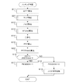
図3は、基本判定手法を改良した手法でノッキング判定を行う処理のフローチャートである。この処理は、TDCパルスの発生に同期してECU5で実行される。
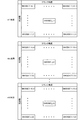
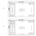
ステップS11では、クランク角度6度毎に実行される高速フーリエ変換によって、周波数5kHz〜20kHzまでの周波数範囲において、5,6,…,19,20kHzの周波数成分強度STFTが算出され、図8(a)に示すように周波数とクランク角度で定義される検出強度マップとして格納される。この図に示す検出強度マップデータSTFT(i,j)のインデクスパラメータiは、燃焼行程開始上死点を基準としたクランク角度を示し、i=1〜11がクランク角度12度〜72度に対応する。またインデクスパラメータjは周波数を示し、j=1〜16がそれぞれ周波数5kHz〜20kHzに対応する。なお、以下に説明する演算処理は、本処理の1回の演算において、すべてのマップデータ、すなわちマップ上の格子点(i=1〜11,j=1〜16)について実行される。
FIG. 3 is a flowchart of a process for performing knocking determination by a method obtained by improving the basic determination method. This process is executed by the
In step S11, frequency component intensities STFT of 5, 6,..., 19, 20 kHz are calculated in the frequency range from 5 kHz to 20 kHz by fast Fourier transform executed every crank angle of 6 degrees, and FIG. ) And stored as a detected intensity map defined by the frequency and the crank angle. The index parameter i of the detected intensity map data STFT (i, j) shown in this figure indicates the crank angle based on the combustion stroke start top dead center, and i = 1 to 11 corresponds to the crank angle of 12 degrees to 72 degrees. To do. An index parameter j indicates a frequency, and j = 1 to 16 corresponds to a frequency of 5 kHz to 20 kHz, respectively. Note that the arithmetic processing described below is executed for all map data, that is, lattice points (i = 1 to 11, j = 1 to 16) on the map in one operation of this processing.
ステップS12では、ノイズ除去処理を実行する。すなわち、後述するノイズ学習処理(ステップS19)において気筒毎に算出されるノイズ成分強度マップデータSNOISE(i,j,k)及び検出強度マップデータSTFT(i,j)を下記式(1)に適用することにより、図8(b)に示すノイズ補正マップデータSTFTC(i,j)を算出する。ノイズ成分強度マップデータSNOISE(i,j,k)(図11参照)のインデクスパラメータkは、気筒を特定するパラメータであり、k=1〜6が#1気筒〜#6気筒に対応する。式(1)には、今回の判定対象気筒kXに対応するノイズ成分強度マップデータSNOISE(i,j,kX)が適用される。なお、式(1)の演算結果が負の値となったときは、ノイズ補正マップデータSTFTC(i,j)は「0」に設定される。
STFTC(i,j)=STFT(i,j)−SNOISE(i,j,kX)×KCDNE (1)
In step S12, noise removal processing is executed. That is, the noise component intensity map data SNOISE (i, j, k) and detected intensity map data STFT (i, j) calculated for each cylinder in the noise learning process (step S19) described later is applied to the following equation (1). Thus, the noise correction map data STTC (i, j) shown in FIG. 8B is calculated. The index parameter k of the noise component intensity map data SNOISE (i, j, k) (see FIG. 11) is a parameter for specifying the cylinder, and k = 1 to 6 corresponds to the # 1 cylinder to the # 6 cylinder. The noise component intensity map data SNOISE (i, j, kX) corresponding to the current determination target cylinder kX is applied to the expression (1). When the calculation result of the expression (1) becomes a negative value, the noise correction map data STTC (i, j) is set to “0”.
STTC (i, j) = STFT (i, j) −SNOISE (i, j, kX) × KCDNE (1)
式(1)のKCDNEは下記式(2)で示される過渡補正係数である。式(2)のNEP及びNEZは、それぞれエンジン回転数NEの今回検出値及び前回検出値(クランク角度720度前の検出値)である。過渡補正係数KCDNEは、エンジン回転数NEが急激に増加すると「1」より大きな値となり、ノイズ成分強度マップデータSNOISE(i,j,kX)を増加方向に補正する一方、エンジン回転数NEが急激に減少すると「1」より小さな値となり、ノイズ成分強度マップデータSNOISE(i,j,kX)を減少方向に補正する。
KCDNE=(NEP/NEZ)2 (2)
KCDNE in the equation (1) is a transient correction coefficient represented by the following equation (2). NEP and NEZ in Expression (2) are the current detection value and the previous detection value (detection value before the crank angle of 720 degrees) of the engine speed NE, respectively. The transient correction coefficient KCDNE takes a value larger than “1” when the engine speed NE increases rapidly, and corrects the noise component intensity map data SNOISE (i, j, kX) in the increasing direction, while the engine speed NE increases rapidly. When the value decreases to a value smaller than “1”, the noise component intensity map data SNOISE (i, j, kX) is corrected in the decreasing direction.
KCDNE = (NEP / NEZ) 2 (2)
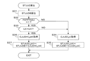
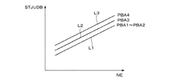
ステップS13では、図4に示すSTJUD算出処理を実行し、ノイズ補正マップデータSTFTC(i,j)の二値化に適用する二値化閾値STJUD(i,j,kX)を算出する。図4のステップS31では、エンジン回転数NE及び吸気圧PBAに応じて図5に示すSTJUDBマップを検索して基本値STJUDBを算出する。STJUDBマップは、エンジン回転数NEが増加するほど基本値STJUDBが増加し、かつ吸気圧PBAが増加するほど基本値STJUDBが増加するように設定されている。ラインL1で示される設定値は、第1所定吸気圧PBA1から第2所定吸気圧PBA2の範囲で適用される。ラインL2及びL3は、それぞれ第3所定吸気圧PBA3及び第4所定吸気圧PBA4に対応し、PBA1<PBA2<PBA3<PBA4なる関係を満たす。 In step S13, the STJUD calculation process shown in FIG. 4 is executed to calculate the binarization threshold value STJUD (i, j, kX) to be applied to the binarization of the noise correction map data STTC (i, j). In step S31 of FIG. 4, the basic value STJUDB is calculated by searching the STJUDB map shown in FIG. 5 according to the engine speed NE and the intake pressure PBA. The STJUDB map is set so that the basic value STJUDB increases as the engine speed NE increases, and the basic value STJUDB increases as the intake pressure PBA increases. The set value indicated by the line L1 is applied in the range from the first predetermined intake pressure PBA1 to the second predetermined intake pressure PBA2. Lines L2 and L3 correspond to the third predetermined intake pressure PBA3 and the fourth predetermined intake pressure PBA4, respectively, and satisfy the relationship PBA1 <PBA2 <PBA3 <PBA4.
ステップS32では、特定運転状態フラグFSTFTADJが「1」であるか否かを判別する。特定運転状態フラグFSTFTADJは、下記の条件1)〜3)がすべて満たされるとき、すなわち特定気筒においてノイズ成分強度が増加する特定運転状態において「1」に設定される。 In step S32, it is determined whether or not the specific operation state flag FSTADADJ is “1”. The specific operation state flag FSTADADJ is set to “1” when all of the following conditions 1) to 3) are satisfied, that is, in the specific operation state in which the noise component intensity increases in the specific cylinder.
1)エンジン冷却水温TWが所定水温TWL(例えば50℃)より高く、
2)エンジン回転数NEが所定高回転数範囲内(例えば2000rpm〜7000rpm)にあり、
3)吸気圧PBAが所定高負荷範囲内(26.7kPa(200mmHg)〜160.2kPa(1200mmHg))にある。
1) The engine cooling water temperature TW is higher than a predetermined water temperature TWL (for example, 50 ° C.)
2) The engine speed NE is within a predetermined high speed range (for example, 2000 rpm to 7000 rpm),
3) The intake pressure PBA is within a predetermined high load range (26.7 kPa (200 mmHg) to 160.2 kPa (1200 mmHg)).
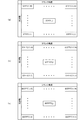
ステップS32の答が肯定(YES)であるときは、判定対象気筒kXが特定気筒kH(例えば#5気筒)であるか否かを判別する(ステップS33)。ステップS32またはS33の答が否定(NO)であるときは、ステップS34に進み、図6(a)に示す、気筒毎に設定されている6つのCJUDマップから判定対象気筒kXに対応するCJUDマップを選択し、各格子点に対応する第1補正係数CJUD(i,j,kX)を取得する。 If the answer to step S32 is affirmative (YES), it is determined whether or not the determination target cylinder kX is a specific cylinder kH (for example, # 5 cylinder) (step S33). If the answer to step S32 or S33 is negative (NO), the process proceeds to step S34, and the CJUD map corresponding to the determination target cylinder kX from the six CJUD maps set for each cylinder shown in FIG. 6A. And the first correction coefficient CJUD (i, j, kX) corresponding to each grid point is acquired.
ステップS35では、下記式(3)に基本値STJUDB及び第1補正係数CJUD(i,j,kX)を適用して、判定対象気筒に対応する二値化閾値STJUD(i,j,kX)を算出する。
STJUD(i,j,kX)=STJUDB×CJUD(i,j,kX) (3)
In step S35, the basic value STJUDB and the first correction coefficient CJUD (i, j, kX) are applied to the following equation (3) to obtain the binarization threshold value STJUD (i, j, kX) corresponding to the determination target cylinder. calculate.
STJUD (i, j, kX) = STJUDB × CJUD (i, j, kX) (3)
ステップS33の答が肯定(YES)であるとき、すなわちエンジン1が特定運転状態にありかつ判定対象気筒kXが特定気筒kHであるときは、図6(b)に示す特定気筒kHに対応して設定されているCJUDHマップから、各格子点に対応する第2補正係数CJUD(i,j,kH)を取得する(ステップS36)。ステップS37では、下記式(4)に基本値STJUDB及び第2補正係数CJUD(i,j,kH)を適用して、判定対象気筒(=特定気筒)に対応する二値化閾値STJUD(i,j,kX)を算出する。
STJUD(i,j,kX)=STJUDB×CJUDH(i,j,kH) (4)
When the answer to step S33 is affirmative (YES), that is, when the
STJUD (i, j, kX) = STJUDB × CJUDH (i, j, kH) (4)
図7は、第1補正係数CJUD及び第2補正係数CJUDHの設定例を説明するためのテーブルを示す図であり、実線が第1補正係数CJUDに対応し、破線が第2補正係数CJUDHに対応する。また図7(a)〜図7(e)は、周波数を示すインデクスパラメータj=1〜3の第1周波数範囲、j=4〜6の第2周波数範囲、j=7〜9の第3周波数範囲、j=10〜12の第4周波数範囲、及びj≧13の第5周波数範囲に対応する。第1補正係数CJUD及び第2補正係数CJUDHは、基本的には、実験によって得られるノイズ成分強度マップデータSNOISE(i,j,k)に基づいて予め設定されており、ノイズ成分強度が高いほど二値化閾値STJUD(i,j,k)を増加させるように設定される。 FIG. 7 is a diagram illustrating a table for explaining a setting example of the first correction coefficient CJUD and the second correction coefficient CJUDH. The solid line corresponds to the first correction coefficient CJUD, and the broken line corresponds to the second correction coefficient CJUDH. To do. FIGS. 7A to 7E show the first frequency range of the index parameter j = 1 to 3 indicating the frequency, the second frequency range of j = 4 to 6, and the third frequency of j = 7 to 9. The range corresponds to the fourth frequency range of j = 10 to 12, and the fifth frequency range of j ≧ 13. The first correction coefficient CJUD and the second correction coefficient CJUDH are basically set in advance based on noise component intensity map data SNOISE (i, j, k) obtained through experiments, and the higher the noise component intensity, the higher the noise component intensity. The binarization threshold value STJUD (i, j, k) is set to increase.
第1補正係数CJUDは、クランク角度を示すインデクスパラメータiが小さくなるほど増加する傾向(すなわち燃焼行程開始上死点に近づくほど増加する傾向)に設定され、またj=10〜12の第4周波数範囲の値が、燃焼行程開始上死点の近傍のクランク角度範囲において他の周波数範囲の値より大きな値に設定されている。また、第2補正係数CJUDHは、全周波数範囲及び全クランク角度範囲で、第1補正係数CJUD以上の値に設定され、特に燃焼行程開始上死点の近傍のクランク角度範囲で、第1補正係数CJUDとの差が増加するように設定されている。
補正係数CJUD,CJUDHの設定は、図7に示す設定例に限るものではなく、周波数範囲で同じ設定するのではなく、周波数毎に異なる設定としてもよい。
The first correction coefficient CJUD is set to a tendency to increase as the index parameter i indicating the crank angle becomes smaller (that is, the tendency to increase as it approaches the top dead center of the combustion stroke), and the fourth frequency range of j = 10 to 12 Is set to a value larger than the values in the other frequency ranges in the crank angle range near the top dead center of the combustion stroke. The second correction coefficient CJUDH is set to a value equal to or greater than the first correction coefficient CJUD in the entire frequency range and the entire crank angle range, and particularly in the crank angle range near the top dead center of the combustion stroke. It is set so that the difference from CJUD increases.
The setting of the correction coefficients CJUD and CJUDH is not limited to the setting example illustrated in FIG. 7, and may be set differently for each frequency instead of the same setting in the frequency range.
図3に戻り、ステップS14では、二値化閾値STJUD(i,j,kX)を用いてノイズ補正マップデータSTFTC(i,j)の二値化を行い、図8(c)に示す二値化マップデータBSTFT(i,j)を算出する。すなわち、ノイズ補正マップデータSTFTC(i,j)が二値化閾値STJUD(i,j,kX)より大きいときは、二値化マップデータBSTFT(i,j)を「1」に設定し、ノイズ補正マップデータSTFTC(i,j)が二値化閾値STJUD(i,j,kX)以下であるときは、二値化マップデータBSTFT(i,j)を「0」に設定する。 Returning to FIG. 3, in step S14, the binarization threshold STJUD (i, j, kX) is used to binarize the noise correction map data STTC (i, j), and the binarization shown in FIG. Map data BSTFT (i, j) is calculated. That is, when the noise correction map data STTC (i, j) is larger than the binarization threshold STJUD (i, j, kX), the binarization map data BSTFT (i, j) is set to “1”, and the noise When the correction map data STTC (i, j) is equal to or less than the binarization threshold STJUD (i, j, kX), the binarization map data BSTFT (i, j) is set to “0”.
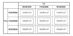
ステップS15では、二値化マップデータBSTFT(i,j)と、図9に示すマスタマップデータBMST(i,j)との適合率PFITを下記式(5)〜(7)により算出する。式(5)及び(6)のΣは、マップ上のすべての格子点(i=1〜11,j=1〜16)についての積算演算を示し、積算値SUMM及びSUMSを式(7)に適用して、適合率PFITが算出される。本実施形態では、図10に示すように、エンジン回転数NE及び吸気圧PBAで定義される9個の運転領域に対応して9個のマスタマップが設定されており、エンジン回転数NE及び吸気圧PBAに応じて1つのマスタマップが選択される。
SUMM=ΣBMST(i,j) (5)
SUMS=ΣSTFTC(i,j)×BMST(i,j) (6)
PFIT=SUMS/SUMM (7)
In step S15, the matching ratio PFIT between the binarized map data BSTFT (i, j) and the master map data BMST (i, j) shown in FIG. 9 is calculated by the following equations (5) to (7). Σ in Equations (5) and (6) indicates the integration calculation for all grid points (i = 1 to 11, j = 1 to 16) on the map, and the integration values SUMM and SUMS are expressed in Equation (7). By applying, the precision PFIT is calculated. In the present embodiment, as shown in FIG. 10, nine master maps are set corresponding to the nine operation regions defined by the engine speed NE and the intake pressure PBA, and the engine speed NE and the suction speed are set. One master map is selected according to the atmospheric pressure PBA.
SUMM = ΣBMST (i, j) (5)
SUMS = ΣSTTC (i, j) × BMST (i, j) (6)
PFIT = SUMS / SUMM (7)
ステップS16では、ステップS15で算出された適合率PFITが、気筒毎に予め設定されている適合率閾値PFITTH(kX)より大きいか否かを判別する。ステップS16の答が肯定(YES)であるときは、ノッキングが発生したと判定し、ノッキングフラグFKNOCKを「1」に設定する(ステップS17)。 In step S16, it is determined whether or not the precision ratio PFIT calculated in step S15 is larger than a precision ratio threshold value PFITTH (kX) preset for each cylinder. If the answer to step S16 is affirmative (YES), it is determined that knocking has occurred, and the knocking flag FKNOCK is set to “1” (step S17).
ステップS16の答が否定(NO)であるときは、ノッキングが発生していないと判定し、ノッキングフラグFKNOCKを「0」に設定する(ステップS18)。この場合、検出強度マップデータSTFT(i,j)はノイズ成分強度を示すデータと考えられるので、図11に示すノイズ成分強度マップの更新を行う(ステップS19)。ノイズ成分強度マップは、#1〜#6気筒のそれぞれに対応して設けられており、ステップS19では、判定対象気筒kXに対応するノイズ成分強度マップのノイズ成分強度マップデータSNOISE(i,j,kX)を、下記式(8)に適用して更新する。式(8)のCSNOISEは、0から1の間の値(例えば「0.5」)に設定されるなまし係数である。
SNOISE(i,j,kX)=SNOISE(i,j,kX)×CSNOISE
+STFT(i,j,kX)×(1−CSNOISE) (8)
If the answer to step S16 is negative (NO), it is determined that knocking has not occurred, and the knocking flag FKNOCK is set to “0” (step S18). In this case, since the detected intensity map data STFT (i, j) is considered as data indicating the noise component intensity, the noise component intensity map shown in FIG. 11 is updated (step S19). The noise component intensity map is provided corresponding to each of the
SNOISE (i, j, kX) = SNOISE (i, j, kX) × CSNOISE
+ STFT (i, j, kX) × (1-CSNOISE) (8)
以上のように本実施形態では、クランク角度6度間隔でノックセンサ11R,11Lの出力信号の周波数成分分析が行われ、その周波数成分分析により得られる、複数の周波数成分の強度の時系列データSTFTが、クランク角度位置及び周波数で定義される検出強度マップとして格納される。検出強度マップデータSTFT(i,j)に基づいて、ノイズ成分強度マップデータSNOISE(i,j,k)が気筒毎に算出され、検出強度マップデータSTFT(i,j)がノイズ成分強度マップデータSNOISE(i,j,k)により補正される。補正後の時系列データであるノイズ補正マップデータSTFTC(i,j)が二値化閾値STJUD(i,j,k)を用いて二値化され、その二値化された時系列データBSTFT(i,j)の2次元マップである二値化マップ(図8(c))と、ノッキングが発生した状態に対応するマスタパターンデータの2次元マップであるマスタマップ(図9)とを比較することより、ノッキングが発生したか否かが判定される。さらに二値化閾値STJUD(i,j,k)の基本値STJUDBがエンジン回転数NE及び吸気圧PBAに応じて算出されるとともに、#1〜#6気筒のそれぞれに対応し、かつノイズ補正マップにおける格子点のそれぞれに対応して設定された第1補正係数CJUDまたは第2補正係数CJUDHを用いて基本値STJUDBを補正することにより、#1〜#6気筒のそれぞれに対応し、かつノイズ補正マップ(2次元マップ)における格子点のそれぞれに対応した二値化閾値STJUD(i,j,k)が算出され、ノイズ補正マップデータSTFTC(i,j)の二値化に適用される。エンジン1の構造あるいはノックセンサ11R,11Lの装着位置に依存して、エンジン運転状態の変化がノイズ成分強度に与える影響が、気筒毎に異なる場合や、ノイズ成分の周波数帯域や出現時期に依存して変化する場合がある。したがって、各気筒に対応したノイズ成分強度マップ(図11)を設け、さらに各気筒に対応し、かつ2次元マップの格子点のそれぞれに対応して二値化閾値STJUD(i,j,k)を設定することにより、気筒毎に異なり、かつマップ格子点毎に異なるノイズ成分強度に対応して、二値化閾値STJUD(i,j,k)をより適切に設定してノイズ成分の影響を低減することが可能となり、ノッキング判定精度を高めることができる。
As described above, in the present embodiment, frequency component analysis of the output signals of
また各気筒に対応したノイズ成分強度マップデータSNOISE(i,j,k)に基づいて、補正係数CJUD,CJUDHが予め設定されており、例えば#5気筒のノイズ発生状態が他の気筒と異なる場合には、図7に示すようにその気筒毎のノイズ成分発生状態に対応した格子点毎の補正係数CJUD,CJUDHの設定を行い、ノイズ成分強度が高いほど二値化閾値STJUDを増加させることによって、ノイズ成分の影響を低減してノッキング判定精度を高めることができる。 Further, correction coefficients CJUD and CJUDH are set in advance based on the noise component intensity map data SNOISE (i, j, k) corresponding to each cylinder. For example, when the noise generation state of the # 5 cylinder is different from the other cylinders As shown in FIG. 7, correction coefficients CJUD and CJUDH are set for each lattice point corresponding to the noise component generation state for each cylinder, and the binarization threshold STJUD is increased as the noise component intensity increases. In addition, the knocking determination accuracy can be increased by reducing the influence of the noise component.
またエンジン1が、特定の気筒においてノイズ成分強度が増加する特定運転状態にあると判定されたとき(FSTFTADJ=1であるとき)は、その特定の気筒(#5気筒)に対応する二値化閾値STJUD(i,j,kH)を増加させるように設定された第2補正係数CJUDHが適用されるので、特定運転状態において特定気筒におけるノッキング判定精度が低下することを防止できる。
Further, when it is determined that the
また図7に示すようにクランク角度位置が、判定対象気筒kXの燃焼行程開始時期に比較的近い範囲(インデクスパラメータiが小さい範囲)で、二値化閾値STJUD(i,j,k)の増加量(第1補正係数CJUDを適用した場合の値からの増加量)が大きくなるように、第2補正係数CJUDHが設定される。ノイズ成分強度は燃焼行程開始時期に比較的近い範囲で大きくなる傾向があるので、クランク角度位置が燃焼行程開始時期に比較的近い範囲で二値化閾値STJUD(i,j,k)の増加量が大きくなるように第2補正係数CJUDHを設定することによって、ノッキング判定精度の低下を防止できる。 Further, as shown in FIG. 7, the binarization threshold value STJUD (i, j, k) increases in a range where the crank angle position is relatively close to the combustion stroke start timing of the determination target cylinder kX (a range where the index parameter i is small). The second correction coefficient CJUDH is set so that the amount (increase from the value when the first correction coefficient CJUD is applied) is increased. Since the noise component intensity tends to increase in a range relatively close to the combustion stroke start timing, the amount of increase of the binarization threshold STJUD (i, j, k) in a range where the crank angle position is relatively close to the combustion stroke start timing By setting the second correction coefficient CJUDH so as to increase, knocking determination accuracy can be prevented from being lowered.
またエンジン回転数NEの今回検出値NEPと、前回検出値NEZとの比(NEP/NEZ)を二乗することよって、過渡補正係数KCDNEが算出され、ノイズ成分強度マップデータSNOISE(i,j,k)に過渡補正係数KCDNEを乗算して、検出強度マップデータSTFT(i,j)から減算することによって、ノイズ補正マップデータSTFTC(i,j)が算出される(式(1))。ノイズ成分強度SNOISEは、エンジン回転数NEが増加するほど増加し、エンジン回転数NEの二乗にほぼ比例することが確認されているので、過渡補正係数KCDNEを用いて補正したノイズ成分強度(SNOISE×KCDNE)を適用することにより、エンジン回転数NEが急変した場合におけるノイズ成分の影響を適切に低減し、エンジン回転数NEが変化する過渡状態においても正確な判定を行うことができる。 Also, the transient correction coefficient KCDNE is calculated by squaring the ratio (NEP / NEZ) of the current detected value NEP and the previous detected value NEZ of the engine speed NE, and noise component intensity map data SNOISE (i, j, k ) Is multiplied by the transient correction coefficient KCDNE and subtracted from the detected intensity map data STFT (i, j) to calculate the noise correction map data STTC (i, j) (formula (1)). The noise component strength SNOISE increases as the engine speed NE increases, and is confirmed to be substantially proportional to the square of the engine speed NE. Therefore, the noise component strength SNOISE corrected using the transient correction coefficient KCDNE (SNOISE × By applying (KCDNE), it is possible to appropriately reduce the influence of noise components when the engine speed NE changes suddenly, and to perform accurate determination even in a transient state where the engine speed NE changes.
本実施形態では、ECU5が、周波数成分分析手段、データ格納手段、ノイズ成分強度算出手段、ノイズ補正手段、二値化手段、及びノッキング判定手段を構成する。
In the present embodiment, the
[第2の実施形態]
図12は、本発明の第2の実施形態にかかるノッキング判定処理のフローチャートである。この処理は、図3に示す処理のステップS13をステップS13aに変更し、ステップS11とS12の間にステップS21を追加し、ステップS15とS16の間にステップS22を追加したものである。以下に説明する点以外は第1の実施形態と同一である。
[Second Embodiment]
FIG. 12 is a flowchart of the knocking determination process according to the second embodiment of the present invention. In this process, step S13 of the process shown in FIG. 3 is changed to step S13a, step S21 is added between steps S11 and S12, and step S22 is added between steps S15 and S16. Except for the points described below, the second embodiment is the same as the first embodiment.
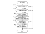
ステップS21では、図13に示すマップ修正処理が実行される。図13のステップS41では、特定運転状態フラグFSTFTADJが「1」であるか否かを判別し、その答が肯定(YES)であるときは、クランク角度のインデクスパラメータi及び周波数のインデクスパラメータjが、検出強度マップ上の特定領域に対応する特定範囲内にあるか否かを判別する。具体的には本実施形態では、図15(a)にハッチングを付して示す領域が特定領域であり、i=1でかつjが1から16の範囲内にあるか否かを判別する。 In step S21, the map correction process shown in FIG. 13 is executed. In step S41 of FIG. 13, it is determined whether or not the specific operation state flag FSTADADJ is “1”. If the answer is affirmative (YES), the crank angle index parameter i and the frequency index parameter j are Then, it is determined whether or not it is within a specific range corresponding to a specific region on the detection intensity map. Specifically, in the present embodiment, it is determined whether the hatched area in FIG. 15A is a specific area, i = 1, and j is in the range of 1 to 16.
ステップS41またはS42の答が否定(NO)であるときは、検出強度マップの修正を行うことなく直ちに処理を終了する。ステップS42の答が肯定(YES)であるときは、特定領域内の格子点のそれぞれに対応して予め設定されたノイズ差分閾値DSNTH(i,j)を取得する(ステップS43)。ノイズ差分閾値DSNTH(i,j)は、実験によって取得される、各格子点におけるノイズ成分強度SNOISE(i,j)に基づいて予め適切な値に設定される。 If the answer to step S41 or S42 is negative (NO), the process immediately ends without correcting the detected intensity map. When the answer to step S42 is affirmative (YES), a noise difference threshold value DSNTH (i, j) set in advance corresponding to each lattice point in the specific region is acquired (step S43). The noise difference threshold value DSNTH (i, j) is set to an appropriate value in advance based on the noise component intensity SNOISE (i, j) at each lattice point obtained by experiment.
ステップS44では、検出強度マップデータSTFT(i,j)及びノイズ成分強度マップデータSNOISE(i,j,kX)を下記式(9)に適用し、ノイズ差分DSNOISE(i,j)を算出する。
DSNOISE(i,j)=STFT(i,j)−SNOISE(i,j,kX) (9)
In step S44, the detected intensity map data STFT (i, j) and the noise component intensity map data SNOISE (i, j, kX) are applied to the following equation (9) to calculate the noise difference DSNOISE (i, j).
DSNOISE (i, j) = STFT (i, j) −SNOISE (i, j, kX) (9)
ステップS45では、ノイズ差分DSNOISE(i,j)がノイズ差分閾値DSNTH(i,j)以上であるか否かを判別し、その答が否定(NO)であるときは、検出強度マップの修正を行うことなく直ちに処理を終了する。ステップS45の答が肯定(YES)であって、検出強度マップデータSTFT(i,j)に含まれるノイズ成分強度が大きいと推定されるときは、当該格子点の検出強度マップデータSTFT(i,j)を「0」に設定し、修正カウンタNMODの値を「1」だけ増加させる(ステップS46)。修正カウンタNMODの値は、本処理の開始前に「0」に設定されており、検出強度マップデータSTFT(i,j)を「0」に修正した格子点の数を示す。 In step S45, it is determined whether or not the noise difference DSNOISE (i, j) is greater than or equal to the noise difference threshold DSNTH (i, j). If the answer is negative (NO), the detection intensity map is corrected. The process ends immediately without performing it. If the answer to step S45 is affirmative (YES) and the noise component intensity included in the detected intensity map data STFT (i, j) is estimated to be large, the detected intensity map data STFT (i, j j) is set to “0”, and the value of the correction counter NMOD is increased by “1” (step S46). The value of the correction counter NMOD is set to “0” before the start of this process, and indicates the number of grid points where the detected intensity map data STFT (i, j) is corrected to “0”.
図13の処理により、エンジン1が特定運転状態にある場合において、ノイズ差分DSNOISE(i,j)がノイズ差分閾値DSNTH(i,j)以上であって、検出強度マップの特定領域内に含まれる格子点の検出強度マップデータSTFT(i,j)が「0」に修正される(修正検出強度マップが生成される)。図15(b)は、修正検出強度マップの一例を示しており、特定領域内の一部のマップデータ(i=1,j=1〜14の格子点におけるデータ)が「0」に設定されている。
When the
図12のステップS13aでは、図14に示すSTJUD算出処理が実行される。図14の処理は、図4のステップS32,S33,S36,及びS37を削除したものに相当する。すなわち、全ての気筒について、上述した式(3)によって二値化閾値STJUD(i,j,kX)の算出が行われる。 In step S13a of FIG. 12, the STJUD calculation process shown in FIG. 14 is executed. The process in FIG. 14 corresponds to the process in which steps S32, S33, S36, and S37 in FIG. 4 are deleted. That is, for all the cylinders, the binarization threshold value STJUD (i, j, kX) is calculated by the above-described equation (3).
図12のステップS22では、下記式(10)の右辺に適合率閾値PFITTH(kX)、積算値SUMM(式(5))、及び修正カウンタNMODの値を適用して、適合率閾値PFITTH(kX)を修正する。
PFITTH(kX)=PFITTH(kX)×(SUMM−NMOD)/SUMM (10)
In step S22 of FIG. 12, the precision ratio threshold value PFITTH (kX), the integrated value SUMM (formula (5)), and the value of the correction counter NMOD are applied to the right side of the following formula (10). ) Is corrected.
PFITTH (kX) = PFITTH (kX) × (SUMM-NMOD) / SUMM (10)
式(10)は、「0」に修正された検出強度マップデータSTFT(i,j)は、ノッキング判定に寄与しなくなることを考慮して、適合率閾値PFTITH(kX)を減少方向に修正するものである。 In equation (10), the detection intensity map data STFT (i, j) corrected to “0” is corrected so as to decrease the precision ratio threshold value PFTITH (kX) in consideration that it does not contribute to the knocking determination. Is.
以上のように本実施形態では、検出強度マップに格納された検出強度マップデータSTFT(i,j)と、対応するノイズ成分強度マップデータSNOISE(i,j,kX)との差分がノイズ差分DSNOISE(i,j)として算出され、ノイズ差分DSNOISE(i,j)に応じて検出強度マップ(図15(a))を修正することにより、修正検出強度マップ(図15(b))が生成され、修正検出強度マップ上の検出強度マップデータSTFT(i,j)がノイズ成分強度マップデータSNOISE(i,j,kX)により補正される。補正後の時系列データであるノイズ補正マップデータSTFTC(i,j)が二値化閾値STJUD(i,j,kX)を用いて二値化され、二値化マップデータBSTFT(i,j)が格納された二値化マップと、マスタマップとの適合率PFITが算出され、その適合率PFITが適合率閾値PFITTH(kX)を超えたときに、ノッキングが発生したと判定される。適合率閾値PFITTH(kX)は、修正検出強度マップの修正度合を示す修正カウンタNMODの値が大きくなるほど減少するように設定される。 As described above, in the present embodiment, the difference between the detected intensity map data STFT (i, j) stored in the detected intensity map and the corresponding noise component intensity map data SNOISE (i, j, kX) is the noise difference DSNOISE. (i, j) is calculated, and a corrected detection intensity map (FIG. 15 (b)) is generated by correcting the detection intensity map (FIG. 15 (a)) according to the noise difference DSNOISE (i, j). The detected intensity map data STFT (i, j) on the corrected detected intensity map is corrected by the noise component intensity map data SNOISE (i, j, kX). Noise correction map data STTC (i, j), which is time series data after correction, is binarized using the binarization threshold value STJUD (i, j, kX), and binarized map data BSTFT (i, j) The matching rate PFIT between the binarized map in which is stored and the master map is calculated. When the matching rate PFIT exceeds the matching rate threshold value PFITTH (kX), it is determined that knocking has occurred. The precision threshold value PFITTH (kX) is set so as to decrease as the value of the correction counter NMOD indicating the correction degree of the correction detection intensity map increases.
ノイズ差分DSNOISE(i,j)を算出することによって実際のノイズ発生状態を気筒毎に、かつ検出強度マップの格子点毎に監視し、ノイズ差分DSNOISE(i,j)に応じて検出強度マップを修正することにより、ノイズ成分強度の大きい気筒あるいは検出強度マップの格子点において、検出強度マップを修正することにより、ノイズ成分の影響が大きい格子点の寄与度を減少させた修正2次元マップが生成され、ノイズ成分の影響を低減することができる。ただし、修正検出強度マップには実際の検出周波成分強度ではない修正データ(「0」)が含まれることとなるため、修正度合を示す修正カウンタNMODの値に応じて適合率閾値PFITTH(kX)を減少させることによって、ノイズ成分の影響を低減してノッキング判定精度を高めることができる。 By calculating the noise difference DSNOISE (i, j), the actual noise occurrence state is monitored for each cylinder and for each grid point of the detection intensity map, and the detection intensity map is determined according to the noise difference DSNOISE (i, j). By correcting, a corrected two-dimensional map in which the contribution of the grid point having a large influence of the noise component is reduced is generated by correcting the detection intensity map in the cylinder having a high noise component intensity or the grid point of the detection intensity map. Thus, the influence of noise components can be reduced. However, since the correction detection intensity map includes correction data (“0”) that is not the actual detection frequency component intensity, the precision ratio threshold value PFITTH (kX) depends on the value of the correction counter NMOD indicating the correction degree. By reducing the noise, it is possible to reduce the influence of the noise component and increase the knocking determination accuracy.
より具体的には、マップデータSTFT(i,j)の修正は、検出強度マップ上の特定領域内において行われる。ノイズ成分の影響が大きい検出強度マップ上の特定領域は予め設定可能であり、その特定領域を対象として検出強度マップデータSTFT(i,j)の修正を行うことにより、修正2次元マップによる判定の精度が低下することを防止できる。さらにノイズ差分DSNOISE(i,j)が予め設定されたノイズ差分閾値DSNTH(i,j)以上であるときに、マップデータSTFT(i,j)を減少方向に修正することにより修正検出強度マップが生成されるので、ノイズ成分の影響を低減し、判定精度の低下を防止できる。さらに修正度合を修正カウンタNMODの値、すなわち修正されたデータの数で示すことにより、修正度合に応じた適合率閾値PFITTH(kX)の変更を容易かつ適切に行うことができる。 More specifically, the map data STFT (i, j) is corrected in a specific area on the detection intensity map. A specific area on the detection intensity map where the influence of the noise component is large can be set in advance. By correcting the detection intensity map data STFT (i, j) for the specific area, determination by the corrected two-dimensional map can be performed. It is possible to prevent the accuracy from decreasing. Further, when the noise difference DSNOISE (i, j) is equal to or larger than a preset noise difference threshold DSNTH (i, j), the correction detection intensity map is obtained by correcting the map data STFT (i, j) in the decreasing direction. Since it is generated, it is possible to reduce the influence of the noise component and prevent the determination accuracy from being lowered. Further, by indicating the correction degree by the value of the correction counter NMOD, that is, the number of corrected data, the precision ratio threshold value PFITTH (kX) according to the correction degree can be changed easily and appropriately.
また、エンジン1が、ノイズ成分強度マップデータSNOISE(i,j,kX)が増加する特定運転状態にあるときに、検出強度マップの修正が行われ、エンジン1が特定運転状態以外の運転状態にあるときは、検出強度マップの修正が行われないので、修正検出強度マップによる判定は必要最小限の運転状態に限定され、特定運転状態以外の運転状態における判定精度に影響を与えないようにすることができる。
Further, when the
本実施形態では、ECU5が、周波数成分分析手段、データ格納手段、ノイズ成分強度算出手段、ノイズ補正手段、二値化手段、ノッキング判定手段、ノイズ差分算出手段、及び2次元マップ修正手段を構成する。
In the present embodiment, the
[変形例1]
図13に示すマップ修正処理では、修正すべき検出強度マップデータSTFT(i,j)を「0」に設定するようにしたが、これに限るものではなく、対応する二値化閾値STJUD(i,j)より小さい値に減少させる修正を行ってもよい。
[Modification 1]
In the map correction process shown in FIG. 13, the detected intensity map data STFT (i, j) to be corrected is set to “0”, but the present invention is not limited to this, and the corresponding binarization threshold value STJUD (i , j) A correction may be made to reduce the value to a smaller value.
[変形例2]
図12に示す処理は、図16に示すように変形してもよい。図16は、図12のステップS13aをステップS13に変更し、第1の実施形態と同様に図4に示すSTJUD算出処理を実行するようにしたものである。この変形例では、第2の実施形態においてもエンジン1が特定運転状態にあるときは、特定気筒に対応する二値化閾値STJUD(i,j,kX)が増加補正され、特定運転状態におけるノッキング判定精度をさらに高めることができる。
[Modification 2]
The process shown in FIG. 12 may be modified as shown in FIG. In FIG. 16, step S13a in FIG. 12 is changed to step S13, and the STJUD calculation process shown in FIG. 4 is executed as in the first embodiment. In this modification, also in the second embodiment, when the
なお本発明は上述した実施形態に限るものではなく、種々の変形が可能である。例えば、特許文献1に示される第3の実施形態と同様に、5kHzから20kHzまでの16個の周波数を、3個または2個の周波数からなる6つの周波数グループに分割し、1つのサンプルタイミングに対応する検出強度マップデータSTFT(i,j)の代表値である検出グループ強度マップデータGSTFTを、周波数グループ内の最大値に設定し、周波数グループ及びクランク角度位置によって定義される2次元マップを用いてノッキング判定を行うようにしてもよい。これにより、ECU5におけるノイズ補正以後の処理負荷を軽減することができる。
The present invention is not limited to the embodiment described above, and various modifications can be made. For example, as in the third embodiment disclosed in
上述した実施形態では、#5気筒におけるノイズ成分強度が他の気筒のノイズ成分強度より大きい例を示したが、本発明は例えば6気筒エンジンのノイズ成分強度及び/またはその周波数特性が、それぞれ異なるような場合であっても適用可能であり、各気筒のノイズ成分強度に適合したノイズ補正及び二値化閾値の設定を行うことができる。 In the embodiment described above, an example in which the noise component intensity in the # 5 cylinder is larger than the noise component intensity of the other cylinders is shown. However, the present invention has different noise component intensity and / or frequency characteristics of a 6-cylinder engine, for example. Even in such a case, the present invention can be applied, and noise correction and binarization threshold setting suitable for the noise component intensity of each cylinder can be performed.
また、上述した実施形態では6気筒エンジンに本発明を適用した例を示したが、本発明は6気筒に限らず2以上の気筒を有するエンジンのノッキング検出に適用可能である。また、燃料を燃焼室内に直接噴射する直噴型のエンジン、あるいは過給機を備えていないエンジンのノッキング検出にも適用可能である。 In the above-described embodiment, an example in which the present invention is applied to a six-cylinder engine has been described. However, the present invention is not limited to six cylinders and can be applied to knock detection of an engine having two or more cylinders. Further, the present invention can also be applied to knock detection of a direct injection type engine that directly injects fuel into a combustion chamber or an engine that does not include a supercharger.
また、ノックセンサ出力のサンプリング周期は20マイクロ秒とし、クランク角度間隔を6度としたが、これに限るものではなく、本発明の目的が達成される範囲内において変更可能である。また、検出強度マップの構成(16行×11列)も同様に変更可能である。また適合率閾値PFITTHは、特許文献1に示されるようにエンジン回転数NE及び吸気圧PBAに応じて気筒毎に設定するようにしてもよい。
The sampling period of the knock sensor output is 20 microseconds and the crank angle interval is 6 degrees. However, the present invention is not limited to this, and can be changed within a range in which the object of the present invention is achieved. Further, the configuration of the detection intensity map (16 rows × 11 columns) can be similarly changed. Further, as shown in
上述した実施形態では、二値化マップデータBSTFT(i,j)とマスタマップBMST(i,j)との類似性(相関性)を示すパラメータとして、適合率PFITを用いたが、例えば二値化マップデータBSTFT(i,j)とマスタマップデータBMST(i,j)の差の絶対値の合計である差分積算値SUMDIFを用いることもできる。この場合、差分積算値SUMDIFは、その値が小さいほど類似性(相関性)が高いことを示すので、差分積算値SUMDIFが差分判定閾値SDLVLより小さいとき、ノッキングが発生したと判定する。 In the embodiment described above, the relevance ratio PFIT is used as a parameter indicating the similarity (correlation) between the binarized map data BSTFT (i, j) and the master map BMST (i, j). It is also possible to use a difference integrated value SUMDIF that is the sum of absolute values of differences between the normalized map data BSTFT (i, j) and the master map data BMST (i, j). In this case, the difference integrated value SUMDIF indicates that the smaller the value is, the higher the similarity (correlation) is. Therefore, when the difference integrated value SUMDIF is smaller than the difference determination threshold SDLVL, it is determined that knocking has occurred.
1 内燃機関
5 電子制御ユニット(周波数成分分析手段、データ格納手段、ノイズ成分強度算出手段、ノイズ補正手段、二値化手段、ノッキング判定手段、ノイズ差分算出手段、2次元マップ修正手段)
11R,11L ノックセンサ
1
11R, 11L knock sensor
Claims (4)
所定クランク角度間隔で前記ノックセンサ出力信号の周波数成分分析を行う周波数成分分析手段と、
前記周波数成分分析により得られる、複数の周波数成分の強度の時系列データを、クランク角度位置及び周波数で定義される2次元マップとして格納するデータ格納手段と、
前記周波数成分強度の時系列データに基づいて、ノイズ成分強度の時系列データを前記複数の気筒のそれぞれに対応して算出するノイズ成分強度算出手段と、
前記2次元マップに格納された周波数成分強度と、対応するノイズ成分強度との差分をノイズ差分として算出するノイズ差分算出手段と、
前記ノイズ差分に応じて前記2次元マップを修正することにより、修正2次元マップを生成する2次元マップ修正手段と、
前記修正2次元マップの時系列データを前記ノイズ成分強度の時系列データにより補正するノイズ補正手段と、
前記ノイズ補正手段による補正後の時系列データを、前記機関の運転状態に応じて設定される二値化閾値を用いて二値化する二値化手段と、
前記二値化された時系列データの2次元マップと、ノッキングが発生した状態に対応するマスタパターンデータの2次元マップとの適合率を算出し、算出した適合率が適合率閾値を超えたときに、ノッキングが発生したと判定するノッキング判定手段とを備え、
前記ノッキング判定手段は、前記2次元マップ修正手段による修正度合が大きくなるほど前記適合率閾値が減少するように、前記適合率閾値を設定することを特徴とする内燃機関のノッキング検出装置。 In a knock detection device for an internal combustion engine for detecting knocking based on an output signal of a knock sensor mounted on an internal combustion engine having a plurality of cylinders,
Frequency component analysis means for performing frequency component analysis of the knock sensor output signal at a predetermined crank angle interval;
Data storage means for storing time-series data of the intensity of a plurality of frequency components obtained by the frequency component analysis as a two-dimensional map defined by crank angle positions and frequencies;
Noise component intensity calculating means for calculating time series data of noise component intensity corresponding to each of the plurality of cylinders based on the time series data of the frequency component intensity;
Noise difference calculation means for calculating a difference between the frequency component intensity stored in the two-dimensional map and the corresponding noise component intensity as a noise difference;
Two-dimensional map correction means for generating a corrected two-dimensional map by correcting the two-dimensional map according to the noise difference;
Noise correction means for correcting the time-series data of the modified two-dimensional map with the time-series data of the noise component intensity;
Binarization means for binarizing the time-series data after correction by the noise correction means using a binarization threshold set in accordance with the operating state of the engine;
When the precision of the two-dimensional map of the binarized time-series data and the master pattern data corresponding to the state where knocking occurs is calculated, and the calculated precision exceeds the precision threshold And a knocking judging means for judging that knocking has occurred,
The knocking detection device for an internal combustion engine, wherein the knocking determination means sets the precision ratio threshold such that the precision ratio threshold decreases as the correction degree by the two-dimensional map correction means increases.
Priority Applications (1)
| Application Number | Priority Date | Filing Date | Title |
|---|---|---|---|
| JP2016082487A JP2017190767A (en) | 2016-04-15 | 2016-04-15 | Knocking detection device of internal combustion engine |
Applications Claiming Priority (1)
| Application Number | Priority Date | Filing Date | Title |
|---|---|---|---|
| JP2016082487A JP2017190767A (en) | 2016-04-15 | 2016-04-15 | Knocking detection device of internal combustion engine |
Publications (1)
| Publication Number | Publication Date |
|---|---|
| JP2017190767A true JP2017190767A (en) | 2017-10-19 |
Family
ID=60084721
Family Applications (1)
| Application Number | Title | Priority Date | Filing Date |
|---|---|---|---|
| JP2016082487A Pending JP2017190767A (en) | 2016-04-15 | 2016-04-15 | Knocking detection device of internal combustion engine |
Country Status (1)
| Country | Link |
|---|---|
| JP (1) | JP2017190767A (en) |
-
2016
- 2016-04-15 JP JP2016082487A patent/JP2017190767A/en active Pending
Similar Documents
| Publication | Publication Date | Title |
|---|---|---|
| US9316556B2 (en) | Knock control apparatus for an internal combustion engine | |
| US10197036B2 (en) | Internal combustion engine control apparatus | |
| JP6312618B2 (en) | Internal combustion engine control device and abnormal combustion detection method | |
| US8326518B2 (en) | Knocking detecting apparatus for internal combustion engine | |
| EP2327868B1 (en) | Frequency spectrum analyzing apparatus | |
| JP5832130B2 (en) | Control device for internal combustion engine | |
| CN107110056B (en) | Knock detection device | |
| JP5944249B2 (en) | Internal EGR amount calculation device for internal combustion engine | |
| JP2012241554A (en) | Control unit of internal combustion engine | |
| US8924134B2 (en) | Knock control device of internal combustion engine | |
| US20130192343A1 (en) | Knock detection device of internal combustion engine | |
| CN110475958B (en) | Method for managing knock in a controlled ignition internal combustion engine | |
| JP6203896B1 (en) | Internal combustion engine knock detection device | |
| US9915240B2 (en) | Method and system for engine auto-ignition detection and mitigation | |
| JP2013133710A (en) | Knock control apparatus for internal combustion engine | |
| JP2017190767A (en) | Knocking detection device of internal combustion engine | |
| JP5691438B2 (en) | In-cylinder pressure waveform processing device | |
| JP6461393B1 (en) | Control device for internal combustion engine | |
| JP6429938B1 (en) | Control device for internal combustion engine | |
| JP2000352349A (en) | Control system for internal combustion engine | |
| JP2007023974A (en) | Estimating method of illustrated average effective pressure of internal combustion engine | |
| JP2024000106A (en) | Misfire determination device for internal combustion engine | |
| JP2013053554A (en) | Control device for internal-combustion engine | |
| JP2010281262A (en) | Knock determining device for internal combustion engine, and knocking control device for internal combustion engine | |
| WO2020104173A1 (en) | Method to determine misfire in a cylinder of an internal combustion engine |