JP2017190646A - Ceiling reinforcement structure and construction method thereof - Google Patents
Ceiling reinforcement structure and construction method thereof Download PDFInfo
- Publication number
- JP2017190646A JP2017190646A JP2016082237A JP2016082237A JP2017190646A JP 2017190646 A JP2017190646 A JP 2017190646A JP 2016082237 A JP2016082237 A JP 2016082237A JP 2016082237 A JP2016082237 A JP 2016082237A JP 2017190646 A JP2017190646 A JP 2017190646A
- Authority
- JP
- Japan
- Prior art keywords
- ceiling
- horizontal
- plate portion
- reinforcing
- plate
- Prior art date
- Legal status (The legal status is an assumption and is not a legal conclusion. Google has not performed a legal analysis and makes no representation as to the accuracy of the status listed.)
- Granted
Links
Images


Abstract
Description
本発明は、天井補強構造およびその施工方法に関する。 The present invention relates to a ceiling reinforcing structure and a construction method thereof.
吊り式の天井構造としてシステム天井が知られている。システム天井は、メインバーとクロスバーとからなる天井下地材を格子状に組み付けてなる天井構造枠を備えている。天井構造枠は、上階床スラブや屋上スラブなどの上部構造躯体から垂設された吊ボルトの下端部に、吊ハンガー(吊金具)を介して支持されている。システム天井では、天井板を天井構造枠に係止して取り付けているため、天井板を容易に取り外すことができ、天井面の任意の場所に開口部を設けることができる。 A system ceiling is known as a suspended ceiling structure. The system ceiling includes a ceiling structural frame formed by assembling a ceiling base material composed of a main bar and a cross bar in a lattice shape. The ceiling structural frame is supported by a lower end portion of a suspension bolt suspended from an upper structural housing such as an upper floor slab or a roof slab via a suspension hanger (suspension fitting). In the system ceiling, the ceiling plate is locked and attached to the ceiling structure frame, so that the ceiling plate can be easily removed and an opening can be provided at an arbitrary location on the ceiling surface.
このような吊り式の天井構造においては、地震時の突上げに対して、吊ボルトを圧縮補強したものが知られている(例えば、特許文献1または特許文献2参照)。特許文献1の天井補強構造では、溝型鋼などの溝状部材を吊ボルトに沿わせるとともに、溝状部材の上端部を上部構造体5に当接させ、溝状部材の下端部を天井下地の支持金具に接続させている。特許文献2の吊り構造では、吊ボルトが鋼管などの管状部材で囲われている。そして、管状部材の上端部は上方のスラブ面に当接して、管状部材の下端部は吊ボルトに螺合された受ナットに係止されている。以上のような構成によって、吊ボルトに作用する圧縮力を溝状部材や管状部材で受けるようになっている。
In such a suspended ceiling structure, a structure in which a suspension bolt is compressed and reinforced against a push-up during an earthquake is known (for example, see Patent Document 1 or Patent Document 2). In the ceiling reinforcing structure of Patent Document 1, a grooved member such as a grooved steel is placed along the suspension bolt, and the upper end of the grooved member is brought into contact with the
ところで、本棚や陳列台やラックなどの家具の転倒を防止するための対策として、家具と天井の間に突っ張り棒を設けることが知られている。しかしながら、システム天井では、天井板が突上げに対して強度を有さないため、突っ張り棒を設けても家具転倒防止の効果を得ることができない。そのため、システム天井の部屋では、家具の下端部を床に固定することで転倒を防止する場合があった。しかし、近年では二重床が採用されることが多く、家具を床に固定できない場合も多くなっている。 By the way, as a measure for preventing the fall of furniture such as a bookshelf, a display stand, and a rack, it is known to provide a tension bar between the furniture and the ceiling. However, in the system ceiling, since the ceiling plate does not have strength against pushing up, the effect of preventing furniture overturning cannot be obtained even if a tension bar is provided. For this reason, in a room with a system ceiling, there is a case where the fall is prevented by fixing the lower end of the furniture to the floor. However, in recent years, a double floor is often employed, and there are many cases where furniture cannot be fixed to the floor.
特許文献1や特許文献2の天井では、吊ボルトの真下の天井下地材付近で突上げに対して強度を得ることができるので、この部分に突っ張り棒を設置することが可能である。しかし、これでは突っ張り棒の設置位置が限定されていまい、家具のレイアウトの自由度が大幅に小さくなってしまう。
In the ceilings of Patent Document 1 and
そこで、本発明は、前記の問題を解決するためになされたものであり、家具のレイアウトの自由度が高く且つ家具の転倒を防止できる天井補強構造およびその施工方法を提供することを課題とする。 Therefore, the present invention has been made to solve the above-described problems, and it is an object of the present invention to provide a ceiling reinforcement structure that has a high degree of freedom in the layout of furniture and can prevent the furniture from falling over, and a construction method therefor. .
前記課題を解決するための請求項1に係る発明は、上部構造体から天井下地材を支持する天井吊材間に架け渡された水平材と、前記水平材に取り付けられた押え材とを備え、前記押え材は、天井板の裏面に当接していることを特徴とする天井補強構造である。 The invention according to claim 1 for solving the above-described problem includes a horizontal member that is spanned between the ceiling suspension members that support the ceiling base material from the upper structure, and a presser member that is attached to the horizontal member. The presser material is a ceiling reinforcing structure in which the presser material is in contact with the back surface of the ceiling plate.
このような構成によれば、天井板を天井裏側から押えることができるので、突っ張り棒の設置可能な範囲が広くなる。これによって、家具のレイアウトの自由度が高くなるとともに、家具の転倒を防止することができる。 According to such a configuration, the ceiling plate can be pressed from the back side of the ceiling, so the range in which the tension bar can be installed is widened. As a result, the degree of freedom in the layout of the furniture is increased, and the furniture can be prevented from falling.
本発明の天井補強構造では、前記水平材は、前記天井板の上方に隙間をあけて配置されており、前記押え材は、前記水平材の下端面と前記天井板の裏面との間に位置する嵌込み部を備えているものが好ましい。このような構成によれば、水平材を天井下地材に干渉させることなく設置できる。さらに、天井板に作用する突上げ力に対する抵抗力を大きくすることができる。 In the ceiling reinforcing structure of the present invention, the horizontal member is disposed above the ceiling plate with a gap therebetween, and the presser member is positioned between the lower end surface of the horizontal member and the back surface of the ceiling plate. The thing provided with the fitting part to perform is preferable. According to such a configuration, the horizontal member can be installed without interfering with the ceiling base material. Furthermore, the resistance force against the thrust force acting on the ceiling plate can be increased.
また、本発明の天井補強構造では、前記押え材は、前記水平材の上面に当接する上端係止板部と、当該上端係止板部から前記天井板の裏面まで垂下する垂下板部と、当該垂下板部から屈曲して前記天井板の裏面に当接する天井板当接板部と、当該天井板当接板部から屈曲して立ち上がる立上板部と、当該立上板部から屈曲して前記水平材の下面に当接する水平材当接板部とを備えているものが好ましい。 Further, in the ceiling reinforcing structure of the present invention, the presser member includes an upper end locking plate portion that contacts the upper surface of the horizontal member, and a hanging plate portion that hangs from the upper end locking plate portion to the back surface of the ceiling plate, A ceiling plate abutting plate portion that is bent from the hanging plate portion and abuts against the back surface of the ceiling plate, a rising plate portion that is bent and rises from the ceiling plate abutting plate portion, and is bent from the rising plate portion. And a horizontal material abutting plate portion that abuts the lower surface of the horizontal material.
前記課題を解決するための請求項4に係る発明は、上部構造体から天井下地材を支持する天井吊材間に架け渡された水平部と、前記水平部と一体に連続する押え部とを備え、前記押え部は、天井板の裏面に当接していることを特徴とする天井補強構造である。
The invention according to
このような構成によれば、請求項1に係る発明と同様に、天井板を天井裏側から押えることができるので、突っ張り棒の設置可能な範囲が広くなる。これによって、家具のレイアウトの自由度が高くなるとともに、家具の転倒を防止することができる。さらに、水平部と押え部が一体化されて、突上げ用の補強部材が形成されているので、請求項1の押え材を水平材に取り付ける工程が省略できる。 According to such a configuration, as in the invention according to claim 1, the ceiling plate can be pressed from the back side of the ceiling, so the range in which the tension bar can be installed is widened. As a result, the degree of freedom in the layout of the furniture is increased, and the furniture can be prevented from falling. Furthermore, since the horizontal portion and the presser portion are integrated to form a push-up reinforcing member, the step of attaching the presser material of claim 1 to the horizontal member can be omitted.
さらに、本発明の天井補強構造は、前記天井吊材を圧縮補強するための圧縮補強材と、ブレース材とをさらに備え、前記圧縮補強材は、前記天井吊材に沿って配置されているものが好ましい。このような構成によれば、天井板に作用する突上げ力を圧縮補強材とブレース材とで受けることができるので、天井板に作用する突上げ力に対する抵抗力をより一層大きくすることができる。 Furthermore, the ceiling reinforcing structure of the present invention further includes a compression reinforcing material for compressively reinforcing the ceiling suspension material, and a brace material, and the compression reinforcement material is disposed along the ceiling suspension material. Is preferred. According to such a configuration, since the thrust force acting on the ceiling plate can be received by the compression reinforcing material and the brace material, the resistance force against the thrust force acting on the ceiling plate can be further increased. .
また、本発明の天井補強構造では、前記圧縮補強材は、前記天井吊材に沿って前記天井吊材の側方に配置される補強材本体と、当該補強材本体の上端部に取り付けられ前記天井吊材に係止される係止部材とを備えているものが好ましい。このような構成によれば、圧縮補強材は、天井吊材に沿わせればよく、天井吊材を挿通させる必要はないので、圧縮補強材を容易に設置することができる。 Further, in the ceiling reinforcing structure of the present invention, the compression reinforcing member is attached to a reinforcing material body disposed on a side of the ceiling hanging material along the ceiling hanging material, and attached to an upper end portion of the reinforcing material body. What is provided with the latching member latched by the ceiling suspension material is preferable. According to such a configuration, the compression reinforcing material only needs to be along the ceiling suspension material, and it is not necessary to insert the ceiling suspension material, so that the compression reinforcement material can be easily installed.
前記課題を解決するための請求項7に係る発明は、上部構造体から天井下地材を支持する天井吊材間に架け渡される水平材に、天井面の裏面に当接する押え材を取り付けて突上げ用補強部材を形成する準備工程と、前記天井吊材の下部の吊ハンガーに、当該吊ハンガーよりも幅広のブレース取付金具を取り付ける支持金具取付工程と、前記押え材を前記天井板の裏面に当接させた状態で、前記水平材の両端部を隣り合う前記ブレース取付金具にそれぞれ固定する補強部材設置工程と、を備えていることを特徴とする天井補強構造の施工方法である。
In the invention according to
このような施工方法によれば、天井裏での突上げ用補強部材の設置作業および位置決め作業を容易に行うことができる。また、この施工方法にて施工された天井補強構造によれば、天井板を天井裏側から押えることができるので、突っ張り棒の設置可能な範囲が広くなる。これによって、家具のレイアウトの自由度が高くなるとともに、家具の転倒を防止することができる。 According to such a construction method, it is possible to easily perform the installation work and the positioning work of the push-up reinforcing member behind the ceiling. Moreover, according to the ceiling reinforcement structure constructed by this construction method, the ceiling plate can be pressed from the back side of the ceiling, so that the range in which the tension bar can be installed is widened. As a result, the degree of freedom in the layout of the furniture is increased, and the furniture can be prevented from falling.
本発明によれば、家具のレイアウトの自由度が高くなるとともに、家具の転倒を防止することができる、といった優れた効果を発揮する。 According to the present invention, it is possible to obtain an excellent effect that the degree of freedom in furniture layout is increased and the furniture can be prevented from falling.
本発明の実施形態に係る天井補強構造およびその施工方法について図面を参照して詳細に説明する。本実施形態では、天井補強構造1をグリッド型のシステム天井に採用した場合を一例として説明する。 A ceiling reinforcing structure and a construction method thereof according to an embodiment of the present invention will be described in detail with reference to the drawings. This embodiment demonstrates as an example the case where the ceiling reinforcement structure 1 is employ | adopted as a grid type system ceiling.
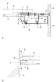
図1に示すように、グリッド型のシステム天井は、天井下地材を構成するメインバー2とクロスバー3とを等間隔をあけて略格子状に組み付けられた天井構造枠4を、例えば、上階床スラブ(上部構造体)5から垂設された複数の吊ボルト(天井吊材)6の下端部に、吊ハンガー7を介して吊下げ支持することで構築される吊天井である。天井構造枠4で区画された各区画部には、天井板8、照明器具(図示せず)や空調機器(図示せず)等が設置されている。本実施形態では、吊ボルト6は、メインバー2とクロスバー3との連結交差部を支持している。
As shown in FIG. 1, the grid type system ceiling includes a
吊ハンガー7は、吊ボルト6の下端部に接続され、メインバー2の上辺縁部を挟み込んで固定する既製の部材である。図2の(b)および図4に示すように、吊ハンガー7は、ハンガー本体9と挟持部材(図示せず)とを備えている。ハンガー本体9は、水平板部9aと垂下板部9bとを備えている。水平板部9aは、吊ハンガー7の上端部に位置し、吊ボルト6が貫通する貫通孔を有している。貫通孔に吊ボルト6が挿通されており、吊ボルト6に螺合したナットNで水平板部9aが挟持されている。これによって、吊ボルト6に吊ハンガー7が接続されている。垂下板部9bは、水平板部9aから連続して下方に延在しており、下端部に挟持部材が設けられている。挟持部材は、垂下板部9bの下端部と合わさってメインバー2の上辺縁部を挟持する。
The
吊ハンガー7の側部には、ブレース取付金具11が設けられている。ブレース取付金具11は、一対の接続板部12と、接続板部12を繋ぐ連結部13とを備えている。接続板部12は、所定の高さ寸法を備え、吊ハンガー7の両側に位置している。接続板部12には、後記するブレース材50の下端部の側面が当接される。ブレース材50は、ビスあるいはボルトなどで接続板部12に接続される。接続板部12の下端部には、ビス孔(図示せず)が形成されており、メインバー2の上辺縁部にビス止めされる。
A
図3にも示すように、連結部13は、平面視コ字形状を呈した板状部材であって、接続板部12と連続している。連結部13の上端には水平板部13aが設けられている。連結部13は、吊ハンガー7を囲うように配置されていて、連結部13の水平板部13aが、吊ハンガー7の水平板部9aに重なる。水平板部13aは、吊ボルト6が挿通する切欠き部13b(図4参照)を有している。切欠き部13bには吊ボルト6が挿通されており、吊ボルト6に螺合したナットNで水平板部9aと水平板部13aとが挟持されている。これによって、ブレース取付金具11が、吊ボルト6の下端部に吊ハンガー7と一体に固定されている。なお、ブレース取付金具11は、接続板部12が、メインバー2に沿う向きとクロスバー3に沿う向きのいずれの向きでも設置可能である。
As shown in FIG. 3, the connecting
図1に示すように、本実施形態に係る天井補強構造1は、水平材20と押え材30と圧縮補強材40とブレース材50を備えている。図2乃至図4にも示すように、水平材20は、リップ付溝型鋼にて構成されており、吊ボルト6,6間に架け渡されている。具体的には、水平材20は、溝の底面部21が吊ボルト6の下端部に固定されたブレース取付金具11の接続板部12に当接して、ビス止めされている(図4参照)。水平材20は、メインバー2あるいはクロスバー3に干渉しないように、天井板8の上方に裏面から所定間隔をあけた高さに設置されている。
As shown in FIG. 1, the ceiling reinforcing structure 1 according to this embodiment includes a
押え材30は、水平材20に取り付けられた部材であって、天井板8の裏面に当接している。図2の(b)および図4に示すように、押え材30は、一枚の板材からなり、上端係止板部31と垂下板部32と天井板当接板部33と立上板部34と水平材当接板部35とを備えている。上端係止板部31は、押え材30の上端部に位置し、水平材20の上端面に当接している。垂下板部32は、上端係止板部31から直角に屈曲して、天井板8の裏面まで垂下している。垂下板部32は、水平材20の一対のリップ部22に当接しており、垂下板部32とリップ部22がビス止めされている。天井板当接板部33は、垂下板部32の下端部から直角に屈曲して、水平方向に延在している。天井板当接板部33は、天井板8の裏面に当接している。立上板部34は、天井板当接板部33から直角に屈曲して立ち上がり、水平材20の底面部21の下面まで延在している。水平材当接板部35は、立上板部34の上端から直角に屈曲して、水平方向に延在している。水平材当接板部35は、水平材20の下面に当接している。天井板当接板部33と立上板部34と水平材当接板部35とで、水平材20の下端面と天井板8の裏面との間に位置する嵌込み部が構成されている。
The
図1および図3に示すように、押え材30は、室内に配置される家具15の上方に配置されており、押え材30が位置する天井板8の表面に突っ張り棒16を当接させることができる。突っ張り棒16は、家具15の上面と天井板8の表面の間に設置される。以上のような押え材30を水平材20に固定して、突上げ用補強部材24が形成されている。
As shown in FIG. 1 and FIG. 3, the
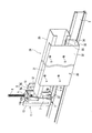
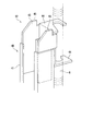
図2および図5に示すように、圧縮補強材40は、吊ボルト6を圧縮補強する部材である。圧縮補強材40は、補強材本体41と係止部材42とを備えている。補強材本体41は、たとえばリップ溝型鋼などの鋼材からなり、吊ボルト6の側方で吊ボルト6に沿って配置されている。補強材本体41の下端部は、ブレース取付金具11の連結部13に溶接あるいはビス止めされている(図2の(b)参照)。図2の(a)および図5に示すように、係止部材42は、当接部43と一対の係止片44,44とを備えてなる。当接部43は、補強材本体41の上端部に挿入され、上端が上部構造体5の下面との当接面45となる。係止片44,44は、吊ボルト6を左右両側から挟み込むものであって、上下方向にオフセットして配置されている。係止片44,44が上下にオフセットしていることで、圧縮補強材40を傾斜させることで、係止片44,44に吊ボルト6を挿通させることができる。
As shown in FIGS. 2 and 5, the
なお、補強材本体41は、リップ溝型鋼に限定されるものではなく、中空の角パイプや押出形材や鉄筋等であってもよい。補強材本体41は、吊ボルト6よりも圧縮強度が大きいものが好ましいが、圧縮強度が吊ボルト6と同等あるいそれ以下であっても圧縮補強することはできる。
The reinforcing
図1に示すように、ブレース材50は、たとえば溝型鋼にて構成されており、ブレース取付金具11の接続板部12に固定される。具体的には、ブレース材50の下端部の側面は、接続板部12に当接され、ビスあるいはボルトなどで接続板部12に接続されている。ブレース材50の上端部(図示せず)は、吊ボルト6の上部あるいは上部構造体5に固定されている。
As shown in FIG. 1, the
次に、図6および図7を参照しながら、前記構成の天井補強構造1の施工方法を説明する。天井補強構造1の施工方法は、準備工程とブレース取付金具取付工程と補強部材設置工程とを備えている。 Next, a construction method of the ceiling reinforcing structure 1 having the above-described configuration will be described with reference to FIGS. 6 and 7. The construction method of the ceiling reinforcing structure 1 includes a preparation process, a brace mounting bracket mounting process, and a reinforcing member installation process.
準備工程は、水平材20に押え材30を取り付けて突上げ用補強部材24を形成する工程である。図6に示すように、本工程では、押え材30の上端係止板部31を水平材20の上端面の所定位置に係止させ、押え材30の垂下板部32から水平材20のリップ部22にビスVを打ち込んで固定する。
The preparation step is a step of attaching the pressing
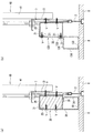
ブレース取付金具取付工程は、図7の(a)の状態の吊ボルト6の下部の吊ハンガー7に、吊ハンガー7よりも幅広のブレース取付金具11を取り付ける工程である。ブレース取付金具取付工程では、吊ハンガー7を固定している上側のナットNを緩め、吊ハンガー7の水平板部9aに連結部13の水平板部13aを重ねる。ナットNを締め付け、吊ハンガー7にブレース取付金具11を取り付ける。さらに、接続板部12の下端部をメインバー2の上辺縁部にビス止めして、ブレース取付金具11でも天井構造枠4を支持する(図7の(b)参照)。
The brace mounting bracket mounting step is a step of mounting a
補強部材設置工程は、突上げ用補強部材24を設置する工程である。図7の(c)に示すように、突上げ用補強部材24は、押え材30を天井板8の裏面に当接させた状態で、水平材20の両端部を隣り合うブレース取付金具11の接続板部12にそれぞれ固定する。このように、押え材30を天井板8の裏面に当接させて、水平材20を固定することで容易に高さ方向の位置決めを行うことができる。さらに、押え材30を予め水平材20に固定して突上げ用補強部材24を形成しているので、天井裏での作業を低減することができ、施工が容易になる。なお、既存の天井に天井補強構造1を追加する場合には、押え材30で押える天井板8の隣の天井板8を取り外して、その開口部を利用して突上げ用補強部材24を設置すると容易に施工することができる。この場合、ブレース取付金具11に水平材20を取り付けるビスは、ブレース取付金具11側から設置するのが好ましい。このようにすれば、取り外した天井板8側からビスを打ち込むことができる。
The reinforcing member installation step is a step of installing the push-up reinforcing
補強部材設置工程では、圧縮補強材40とブレース材50の設置も行う。圧縮補強材40とブレース材50は通常の施工方法にて設置される。
In the reinforcing member installation step, the
以上のような天井補強構造1および施工方法によれば、天井板8を押え材30で天井裏側から押えることができるので、天井板8が浮き上がることがなく、その部分において突上げに対する抵抗力を確保することができる。押え材30は、隣り合う吊ボルト6,6間に設置することができるので、突っ張り棒の設置可能な範囲が広くなる。これによって、家具のレイアウトの自由度が高くなるとともに、家具の転倒を防止することができる。さらに、水平材20と水平材20との間にさらに水平材を設けて、押え材30を取り付けるようにすれば、天井面の任意の場所に押え材30を設置することができる。
According to the ceiling reinforcing structure 1 and the construction method as described above, the
本実施形態では、水平材20が、天井板8の上方に隙間をあけて配置されているので、水平材20を天井構造枠4に干渉させることなく設置できる。また、押え材30は、水平材20の下端面と天井板8の裏面との間に嵌め込まれているので、天井板8に作用する突上げ力に対する抵抗力を大きくすることができる。
In this embodiment, since the
また、押え材30は、上端係止板部31と垂下板部32とを備えているので、水平材20の上端面に上端係止板部31を係止させた状態で、垂下板部32にビスVを打って、押え材30を容易に固定することができる。
Further, since the
さらに、本実施形態では、圧縮補強材40とブレース材50とをさらに備えているので、突上げ用補強部材24が受けた突上げ力を、吊ボルト6を介さずに上部構造体5へ伝達することができる。よって、天井板8に作用する突上げ力に対する抵抗力をより一層大きくすることができるとともに、吊ボルト6の圧縮変形を防止できる。
Furthermore, in this embodiment, since the
以上、本発明を実施するための形態についてそれぞれ説明したが、本発明は前記の実施形態に限定されず、本発明の趣旨を逸脱しない範囲で、材質、形状や大きさなど適宜設計変更が可能である。たとえば水平材20と押え材30(突上げ用補強部材24)の形状は、前記実施形態のものに限定されるものではない。図8に水平材20と押え材30の他の形態を示す。図8の(a)の水平材20には、溝の内部に木製の角材23が挿入されている。押え材30の垂下板部32から角材23に向かってビスVが打ち込まれており、押え材30と角材23が固定されている。このような構成によれば、水平材20が角材23によって補強されて、突上げ力に対する抵抗力をより一層大きくすることができる。
As mentioned above, although the form for implementing this invention was each demonstrated, this invention is not limited to the said embodiment, A design change, such as a material, a shape, and a magnitude | size, is suitably possible in the range which does not deviate from the meaning of this invention. It is. For example, the shapes of the
一方、図8の(b)の押え材130は、垂下板部32の下端部の天井板当接板部133が、水平材20の下側ではなく、半端側に屈曲して、天井板8の裏面に当接している。天井板当接板部133の先端からは、立上板部134が立ち上っている。立上板部134の上端からは、水平材20側に屈曲する水平板部135が設けられている。水平板部135の先端(垂下板部32側)には、垂下板部32に当接する立上板部136が設けられている。立上板部136と垂下板部32には、ビスVが打ち込まれ、水平材20の下側のリップ部22にビス止めされている。このような構成によれば、水平材20の下方からずれた位置で、天井板8を押えることができるので、突っ張り棒の設置位置をさらに広くすることができる。
On the other hand, in the
また、前記実施形態では、水平材20と押え材30とが別部材で形成され、押え材30を水平材20に取り付けることで、突上げ用補強部材24が形成されているが、これに限定されるものではない。図9に示すように、水平材20に相当する水平部220と、押え材30に相当する押え部230とを一体的に備えた突上げ用補強部材224としてもよい。押え部230は、水平部220の下面221から連続して形成されており、下面221から屈曲された垂下板部231と天井板当接板部232と立上板部233とを備えている。垂下板部231と天井板当接板部232と立上板部233は、合わせて上向きに開口する断面コ字状を呈している。押え部230は、水平部220の長手方向に延在している。水平部220の下方にクロスバー3が交差する部分は、押え部230が形成されておらず、クロスバー3の通過空間235が形成されている。通過空間235は、水平部220の長手方向中間部に形成されている。図10に示すように、このような構成の突上げ用補強部材224によれば、突上げ用補強部材224を製造するに際して、押え材を水平材に取り付ける工程を省略することができる。突上げ用補強部材224は、水平部220の両端をブレース取付金具11の接続板部12にそれぞれ固定するだけで、天井裏に設置され、押え部230が天井板8の裏面に当接される。天井板8の裏側に突出するクロスバー3は、通過空間235に位置するので、突上げ用補強部材224と干渉しない。なお、図10において、突上げ用補強部材224は、前記実施形態と同じ構成であるので、同様の部材には同じ符号を付して説明を省略する。
In the above embodiment, the
なお、押え部230の形状は前記形状に限定されるものではない。たとえば、垂下板部が水平部の側面から面一の状態で連続して垂下する形状であってもよい。また、クロスバーの通過空間の形成位置は、水平部の長手方向中間部に限定されるものではなく、クロスバーの位置に対応して形成される。たとえば、突上げ用補強部材が二本のクロスバーを跨ぐ場合には、水平部の長さを三等分した二箇所の分割位置に通過空間が形成される。
The shape of the
前記実施形態では、システム天井に天井補強構造1を採用した場合を例に挙げて説明したが、本発明は、システム天井以外の吊り式天井であっても適用できるのは勿論である。また、水平材20を取り付ける位置はブレース取付金具11に限定されるものではなく、圧縮補強材40やブレース材50や他の金具であってもよい。
In the above-described embodiment, the case where the ceiling reinforcing structure 1 is adopted for the system ceiling has been described as an example. However, the present invention can be applied to a suspended ceiling other than the system ceiling. Further, the position where the
1 天井補強構造
2 メインバー(天井下地材)
3 クロスバー(天井下地材)
5 上部構造体
6 吊ボルト(天井吊材)
7 吊ハンガー
8 天井板
11 ブレース取付金具
20 水平材
24 突上げ用補強部材
30 押え材
31 上端係止板部
32 垂下板部
33 天井板当接板部
34 立上板部
35 水平材当接板部
40 圧縮補強材
41 補強材本体
42 係止部材
50 ブレース材
1
3 Crossbar (ceiling base material)
5
7
Claims (7)
前記水平材に取り付けられた押え材とを備え、
前記押え材は、天井板の裏面に当接している
ことを特徴とする天井補強構造。 A horizontal material spanned between the ceiling suspension material that supports the ceiling base material from the upper structure,
A presser member attached to the horizontal member,
The pressing member is in contact with the back surface of the ceiling board.
前記押え材は、前記水平材の下端面と前記天井板の裏面との間に位置する嵌込み部を備えている
ことを特徴とする請求項1に記載の天井補強構造。 The horizontal member is arranged with a gap above the ceiling plate,
The ceiling reinforcing structure according to claim 1, wherein the presser member includes a fitting portion positioned between a lower end surface of the horizontal member and a back surface of the ceiling plate.
ことを特徴とする請求項2に記載の天井補強構造。 The presser member includes an upper end locking plate portion that contacts the upper surface of the horizontal member, a hanging plate portion that hangs from the upper end locking plate portion to the back surface of the ceiling plate, and a bent bent portion from the hanging plate portion. A ceiling plate contact plate portion that contacts the back surface of the plate, a rising plate portion that bends and rises from the ceiling plate contact plate portion, and a horizontal that is bent from the rising plate portion and contacts the lower surface of the horizontal member The ceiling reinforcing structure according to claim 2, further comprising a material abutting plate portion.
前記水平部と一体に連続する押え部とを備え、
前記押え部は、天井板の裏面に当接している
ことを特徴とする天井補強構造。 A horizontal portion spanned between the ceiling suspension material that supports the ceiling base material from the upper structure,
A presser part that is continuous with the horizontal part,
The said presser part is contact | abutting to the back surface of a ceiling board. The ceiling reinforcement structure characterized by the above-mentioned.
前記圧縮補強材は、前記天井吊材に沿って配置されている
ことを特徴とする請求項1乃至請求項4のいずれか1項に記載の天井補強構造。 A compression reinforcing material for compressively reinforcing the ceiling suspension material, and a brace material;
The ceiling reinforcing structure according to any one of claims 1 to 4, wherein the compression reinforcing material is disposed along the ceiling suspension material.
ことを特徴とする請求項5に記載の天井補強構造。 The compression reinforcing material includes a reinforcing material body disposed on a side of the ceiling hanging material along the ceiling hanging material, and a latch attached to the upper end portion of the reinforcing material body and locked to the ceiling hanging material. The ceiling reinforcing structure according to claim 5, further comprising: a member.
前記天井吊材の下部の吊ハンガーに、当該吊ハンガーよりも幅広のブレース取付金具を取り付けるブレース取付金具取付工程と、
前記押え材を前記天井板の裏面に当接させた状態で、前記水平材の両端部を隣り合う前記ブレース取付金具にそれぞれ固定する補強部材設置工程と、を備えている
ことを特徴とする天井補強構造の施工方法。 A preparatory step of forming a reinforcing member for raising by attaching a presser material that abuts on the back surface of the ceiling surface to a horizontal material spanned between the ceiling suspension materials that support the ceiling base material from the upper structure,
A brace mounting bracket mounting step for mounting a brace mounting bracket that is wider than the hanging hanger to the hanging hanger at the bottom of the ceiling hanging material,
And a reinforcing member installation step for fixing both ends of the horizontal member to the adjacent brace mounting brackets in a state where the presser material is in contact with the back surface of the ceiling plate. Reinforcement construction method.
Priority Applications (1)
| Application Number | Priority Date | Filing Date | Title |
|---|---|---|---|
| JP2016082237A JP6723060B6 (en) | 2016-04-15 | 2016-04-15 | Ceiling reinforcement structure and its construction method |
Applications Claiming Priority (1)
| Application Number | Priority Date | Filing Date | Title |
|---|---|---|---|
| JP2016082237A JP6723060B6 (en) | 2016-04-15 | 2016-04-15 | Ceiling reinforcement structure and its construction method |
Publications (3)
| Publication Number | Publication Date |
|---|---|
| JP2017190646A true JP2017190646A (en) | 2017-10-19 |
| JP6723060B2 JP6723060B2 (en) | 2020-07-15 |
| JP6723060B6 JP6723060B6 (en) | 2020-08-19 |
Family
ID=60084595
Family Applications (1)
| Application Number | Title | Priority Date | Filing Date |
|---|---|---|---|
| JP2016082237A Active JP6723060B6 (en) | 2016-04-15 | 2016-04-15 | Ceiling reinforcement structure and its construction method |
Country Status (1)
| Country | Link |
|---|---|
| JP (1) | JP6723060B6 (en) |
Cited By (3)
| Publication number | Priority date | Publication date | Assignee | Title |
|---|---|---|---|---|
| JP2020051210A (en) * | 2018-09-28 | 2020-04-02 | 大和ハウス工業株式会社 | Ceiling structure |
| JP2020090792A (en) * | 2018-12-03 | 2020-06-11 | 株式会社竹中工務店 | Ceiling structure |
| KR102139191B1 (en) * | 2019-03-14 | 2020-07-30 | 광건티앤씨 주식회사 | Ceiling panel installation structure |
Citations (10)
| Publication number | Priority date | Publication date | Assignee | Title |
|---|---|---|---|---|
| JP2001049790A (en) * | 1999-08-11 | 2001-02-20 | Daiwa House Ind Co Ltd | Ceiling structure and ceiling construction method |
| JP2007154589A (en) * | 2005-12-08 | 2007-06-21 | Nippon Light Metal Co Ltd | Ceiling material with joist, and ceiling structure using the same |
| JP2012162873A (en) * | 2011-02-04 | 2012-08-30 | Kirii Construction Materials Co Ltd | Ceiling structure and fixing metal fitting for brace material and ceiling finish board |
| JP2013014895A (en) * | 2011-07-01 | 2013-01-24 | Mitsui Home Co Ltd | Structure for fixing object to be fixed to face material |
| JP2013092000A (en) * | 2011-10-27 | 2013-05-16 | Misawa Homes Co Ltd | Mounting structure of lattice panel |
| JP2013224574A (en) * | 2012-03-23 | 2013-10-31 | Sato Katako Seisakusho:Kk | Ceiling substrate structure |
| JP2014055461A (en) * | 2012-09-13 | 2014-03-27 | Taisei Corp | Aseismatic ceiling structure |
| JP2014224375A (en) * | 2013-05-15 | 2014-12-04 | 清水建設株式会社 | Hanging ceiling structure |
| JP2015081496A (en) * | 2013-10-24 | 2015-04-27 | 株式会社奥村組 | Suspended ceiling backing structure |
| JP2015194021A (en) * | 2014-03-31 | 2015-11-05 | 株式会社オクオ | Compression member locking bracket |
-
2016
- 2016-04-15 JP JP2016082237A patent/JP6723060B6/en active Active
Patent Citations (10)
| Publication number | Priority date | Publication date | Assignee | Title |
|---|---|---|---|---|
| JP2001049790A (en) * | 1999-08-11 | 2001-02-20 | Daiwa House Ind Co Ltd | Ceiling structure and ceiling construction method |
| JP2007154589A (en) * | 2005-12-08 | 2007-06-21 | Nippon Light Metal Co Ltd | Ceiling material with joist, and ceiling structure using the same |
| JP2012162873A (en) * | 2011-02-04 | 2012-08-30 | Kirii Construction Materials Co Ltd | Ceiling structure and fixing metal fitting for brace material and ceiling finish board |
| JP2013014895A (en) * | 2011-07-01 | 2013-01-24 | Mitsui Home Co Ltd | Structure for fixing object to be fixed to face material |
| JP2013092000A (en) * | 2011-10-27 | 2013-05-16 | Misawa Homes Co Ltd | Mounting structure of lattice panel |
| JP2013224574A (en) * | 2012-03-23 | 2013-10-31 | Sato Katako Seisakusho:Kk | Ceiling substrate structure |
| JP2014055461A (en) * | 2012-09-13 | 2014-03-27 | Taisei Corp | Aseismatic ceiling structure |
| JP2014224375A (en) * | 2013-05-15 | 2014-12-04 | 清水建設株式会社 | Hanging ceiling structure |
| JP2015081496A (en) * | 2013-10-24 | 2015-04-27 | 株式会社奥村組 | Suspended ceiling backing structure |
| JP2015194021A (en) * | 2014-03-31 | 2015-11-05 | 株式会社オクオ | Compression member locking bracket |
Cited By (5)
| Publication number | Priority date | Publication date | Assignee | Title |
|---|---|---|---|---|
| JP2020051210A (en) * | 2018-09-28 | 2020-04-02 | 大和ハウス工業株式会社 | Ceiling structure |
| JP7185466B2 (en) | 2018-09-28 | 2022-12-07 | 大和ハウス工業株式会社 | ceiling structure |
| JP2020090792A (en) * | 2018-12-03 | 2020-06-11 | 株式会社竹中工務店 | Ceiling structure |
| JP7107483B2 (en) | 2018-12-03 | 2022-07-27 | 株式会社竹中工務店 | ceiling structure |
| KR102139191B1 (en) * | 2019-03-14 | 2020-07-30 | 광건티앤씨 주식회사 | Ceiling panel installation structure |
Also Published As
| Publication number | Publication date |
|---|---|
| JP6723060B6 (en) | 2020-08-19 |
| JP6723060B2 (en) | 2020-07-15 |
Similar Documents
| Publication | Publication Date | Title |
|---|---|---|
| JP5078493B2 (en) | Reinforcing bracket for ceiling and suspended ceiling using the same | |
| JP5746874B2 (en) | Ceiling structure and brace material and ceiling finishing plate fixing bracket | |
| JP2007070978A (en) | Reinforcing fitting for hung ceiling | |
| JP6253948B2 (en) | Suspended ceiling foundation structure | |
| JP6723060B2 (en) | Ceiling reinforcement structure and construction method | |
| JP6412664B2 (en) | Ceiling foundation structure | |
| JP2012202032A (en) | Earthquake-resistant structure of suspended ceiling | |
| JP3176767U (en) | Hanging bolt steady rest device | |
| JP2015059410A (en) | Ceiling structure, connecting hardware, and reinforcement structure | |
| JP2013181342A (en) | Ceiling substrate structure | |
| JP5374070B2 (en) | Ceiling support structure | |
| JP2005042411A (en) | Structure for fixing computer to floor surface | |
| JP6117960B1 (en) | Suspended ceiling foundation structure and repair method of existing suspended ceiling foundation | |
| JP2023083635A (en) | Brace bottom part fixture | |
| JP6143091B2 (en) | Suspended ceiling reinforcing member and suspended ceiling structure provided with the same | |
| KR102126921B1 (en) | Installation bracket for exterior panel | |
| JP2014095245A (en) | Installation structure of wall-mounted toilet bowl and wall-mounted toilet bowl | |
| KR102322585B1 (en) | Sleeper for formwork | |
| KR20140014758A (en) | Celling louver | |
| JP2023083636A (en) | Brace bottom part fixture | |
| JP7202849B2 (en) | Mounting structure for unit room | |
| JP6886788B2 (en) | Seismic ceiling structure | |
| JP5723817B2 (en) | Attaching the field edge | |
| CN110249100B (en) | Head for beam joining | |
| JP2018025028A (en) | Support member and unit bath supported by support member |
Legal Events
| Date | Code | Title | Description |
|---|---|---|---|
| A521 | Request for written amendment filed |
Free format text: JAPANESE INTERMEDIATE CODE: A523 Effective date: 20160428 |
|
| A621 | Written request for application examination |
Free format text: JAPANESE INTERMEDIATE CODE: A621 Effective date: 20190228 |
|
| A977 | Report on retrieval |
Free format text: JAPANESE INTERMEDIATE CODE: A971007 Effective date: 20191209 |
|
| A131 | Notification of reasons for refusal |
Free format text: JAPANESE INTERMEDIATE CODE: A131 Effective date: 20200114 |
|
| A521 | Request for written amendment filed |
Free format text: JAPANESE INTERMEDIATE CODE: A523 Effective date: 20200205 |
|
| TRDD | Decision of grant or rejection written | ||
| A01 | Written decision to grant a patent or to grant a registration (utility model) |
Free format text: JAPANESE INTERMEDIATE CODE: A01 Effective date: 20200609 |
|
| A61 | First payment of annual fees (during grant procedure) |
Free format text: JAPANESE INTERMEDIATE CODE: A61 Effective date: 20200623 |
|
| R150 | Certificate of patent or registration of utility model |
Ref document number: 6723060 Country of ref document: JP Free format text: JAPANESE INTERMEDIATE CODE: R150 |
|
| R250 | Receipt of annual fees |
Free format text: JAPANESE INTERMEDIATE CODE: R250 |